the methodology of the gas turbine efficiency...
TRANSCRIPT

archivesof thermodynamics
Vol. 37(2016), No. 4, 19–35
DOI: 10.1515/aoter-2016-0025
The methodology of the gas turbine
efficiency calculation
JANUSZ KOTOWICZMARCIN JOBMATEUSZ BRZĘCZEK∗
KRZYSZTOF NAWRATJANUSZ MĘDRYCH
Silesian University of Technology, Institute of Power Engineering andTurbomachinery, Konarskiego 18, 44-100 Gliwice, Poland
Abstract In the paper a calculation methodology of isentropic efficiencyof a compressor and turbine in a gas turbine installation on the basis ofpolytropic efficiency characteristics is presented. A gas turbine model isdeveloped into software for power plant simulation. There are shown thecalculation algorithms based on iterative model for isentropic efficiency ofthe compressor and for isentropic efficiency of the turbine based on theturbine inlet temperature. The isentropic efficiency characteristics of thecompressor and the turbine are developed by means of the above mentionedalgorithms. The gas turbine development for the high compressor ratios wasthe main driving force for this analysis. The obtained gas turbine electricefficiency characteristics show that an increase of pressure ratio above 50is not justified due to the slight increase in the efficiency with a significantincrease of turbine inlet combustor outlet and temperature.
Keywords: Gas turbine; Polytropic efficiency; Isentropic efficiency
Nomenclature
0 − 9 – characteristic pointsa – air / flue gasAF – air filter
∗Corresponding Author. E-mail: [email protected]
UnauthenticatedDownload Date | 5/8/17 6:35 PM

20 J. Kotowicz, M. Job, M. Brzęczek, K. Nawrat and J. Mędrych
c – cooling airC – compressorCCGT – combined cycle gas turbineCCH – combustor chamberCO – coolerCOT – combustor outlet temperature
C – average specific heatG – generatorLHV – lower heating valuem – mass flowp – pressureR – individual gas constant valueSC – simple cyclet or T – temperatureT – turbineTBC – thermal barrier coatingsTIT – turbine inlet temperatureQ – heat flux(C) – conservative scenario(O) – optimistic scenario
Greek symbols
β – pressure ratio∆ – derivationη – efficiencyµ – polytropic exponent
Subscripts
CCGT – combined cycle gas turbineel – electricalest – establishf – fuelFC – fuel compressorgross – grossGT – gas turbinei – internal/isentropicin – inletm – mechanicalmax – maximalnet – netout – outletp – polytropics – waste heatST – steam turbinet – thermalζ – pressure loss˙ – division of subscripts
UnauthenticatedDownload Date | 5/8/17 6:35 PM

The methodology of the gas turbine efficiency calculation 21
Superscripts
C – compressorp – polytropicT – turbineη – efficiencyµ – polytropic exponent
1 Introduction
Gas turbines are the machines consisting of the air compressor and theexpander, mostly connected together by common shaft, and of a combustionchamber placed between them. In the energy sector these machines are usedas an autonomous units called simple cycle (SC) or as a components of agas turbine combined cycle gas turbine units (CCGT). The simple cycleunits are characterized by lower powers and light, container-constructionallowing for easy transport. Gas turbines used in CCGT units often haveelectric power exceeding 300 MW. In countries such as Poland, where theratio of natural gas to coal prices is unfavorable – SC units are not builtdue to the lack of investment profitability, gas turbines are working thereonly in a combined cycle [1–3].
Thermal efficiency of CCGT units is defined by the relationship
ηt CCGT =NiGT +NiST
Qin, (1)
where NiGT , NiST are internal power of gas turbine and steam turbine,respectively, and Qin is a heat flow fed to the gas turbine. Equation (1)can be rewritten as
ηt CCGT = ηt GT + ηtST (1 − ηt GT ) , (2)
where ηt GT and ηt ST are the thermal efficiency of a gas turbine and steamturbine, respectively, and are defined as
ηt GT =NiGT
Qin, (3)
ηt ST =NiST
Q4a, (4)
where Q4a is a heat flow at the gas turbine outlet. Relationship (2) ispresented graphically in Fig. 1.
UnauthenticatedDownload Date | 5/8/17 6:35 PM

22 J. Kotowicz, M. Job, M. Brzęczek, K. Nawrat and J. Mędrych
Figure 1: Thermal efficiency of the CCGT unit in a function of gas turbine and steamturbine cycle thermal efficiencies.
Currently achieved thermal efficiency of the gas turbines are around40%, and the steam turbine cycle they are up to above 35%. Thus, the leftside of vertical axis shows the currently achieved efficiency of the CCGTunits. The right side of Eq. (2) represents the potential for increasing theCCGT efficiency. The derivation of Eq. (2) returns the condition for theCCGT efficiency increase
∆ηtCCGT =∂ηt CCGT
∂ηt GT∆ηt GT +
∂ηt CCGT
∂ηt ST∆ηt ST . (5)
Based on Eq.(5) for the values of ∆ηt GT = 0.4 and ∆ηt ST = 0.35 thederivatives of ∂ηtCCGT
∂ηt GT
∼= 0.65 and ∂ηtCCGT
∂ηt ST
∼= 0.6 are determined [1,2]. Thismeans that the increase in the gas turbine efficiency ∆ηt GT by 1 pp trans-lates into a higher CCGT efficiency increase than in the analogous rise insteam turbine cycle (∆ηt ST ). This is the first argument suggesting a searchdirection to increase CCGT efficiency in the first place through the increasein gas turbine efficiency. The second, but much more important argumentis the unit investment cost (referred to 1 MW of generated power), whichin the case of the gas turbine installation are 4–5 times lower than in steamturbine part. Therefore, the present paper concentrates on gas turbines[3–7].
The gas turbine efficiency depends primarily on the compressor pressureratio and the highest temperature in the cycle, which is the combustor out-let temperature (COT). However, usually considered as the most importanttemperature in the gas turbine cycle is the average turbine inlet tempera-ture (TIT), defined by ISO-2314 standard. For stoichiometric combustion
UnauthenticatedDownload Date | 5/8/17 6:35 PM

The methodology of the gas turbine efficiency calculation 23
conditions the COT would significantly exceed the value of 2000 ◦C. Today,most manufactures use the COT of 1500 ◦C. Only one of the leading pro-ducers introduced the COT at the level of 1600 ◦C, and conducts researchtowards the use of 1700◦C [8,9]. In comparison TIT achieves value rangeof 1300–1400 ◦C, rarely reaching 1500 ◦C.
Limitations of these temperatures result from the application of ther-mal barrier coatings (TBC), which cover elements exposed to the highesttemperatures. Assumed that currently used TBC allow for continuous op-eration at a temperature not exceeding 1200 ◦C. Presently used coolingtechnologies allow for the flue gas temperature reduction at the cooled sur-face by ∆t = 300–400 K, therefore the highest temperature (COT or TIT)can reach 1500–1600 ◦C. Raising TIT by 100 to 200 K is associated withthe increase in ∆t, i.e., to the value ∆t = 500–600 K. Such actions werethe object of scrutiny of producers more than 10 years ago [10,11], butthere is no information in the literature about their realization. An ex-ception is the paper Hada et al. [12], from Mitsubishi Heavy Industries,Ltd., which indicates that the key to the creation of a J-class turbine withTIT = 1600 ◦C (M701J and M501J for 50 Hz and 60 Hz, respectively),i.e., the temperature higher by 100 ◦C than the reference G-class, was toimprove cooling technology and search for materials with lower thermalconductivity of TBC. Each of them allowed to increase TIT by 50 ◦C. Dataprovided there also suggests that cooling technologies allow to reduce thesurface temperature by ∆t = 550 K in the G-class turbine, while the TBCwith lowered temperature by 50 K, allows to use the alloys with allowabletemperature of 700–900 ◦C. For the J-class turbine the cooling technologyreduces surface temperature by ∆t = 600 K, and the TBC by 100 K (henceTIT = 900+ 600+ 100 = 1600;◦C). In Japan there is also ongoing researchon the turbine with TIT = 1700 ◦C [13].
In the case of the analyzes of gas turbines in a wide range of pressureratio and TIT a significant mistake is to assume constant internal efficiencyvalue, therefore the paper presents the calculation method of the gas tur-bine with variable isentropic efficiency of the compressor and the turbinedepending on the pressure ratio and TIT.
2 Gas turbine model
The gas turbine is modeled using commercial PC-based software applica-tion for design and performance evolution of thermal power plant systems,
UnauthenticatedDownload Date | 5/8/17 6:35 PM

24 J. Kotowicz, M. Job, M. Brzęczek, K. Nawrat and J. Mędrych
GateCycle. Figure 2 shows a scheme of the gas turbine. Composition andparameters of ambient air are set according to ISO-2314 (t0a= 15◦C, p0a =101.325 kPa). Assumed fuel is the natural gas composed of: 98.21% CH4,1.27% N2, and 0.52% CO2, with temperature and pressure at the com-bustor inlet equal to 15 ◦C and 3.5 MPa, respectively. The lower heatingvalue (LHV) of the fuel is equal to LHV= 48 110.54 kJ/kg (according toISO 6976:1995/1996). Table 1 summarizes the main parameters of the gasturbine installation.
Figure 2: Scheme of the gas turbine: AF – air filter, C – compressor, CO – cooler, CCH– combustion chamber, T – turbine, G – generator, Qs – waste heat.
Table 1: The main parameters of the gas turbine installation.
Parameter Symbol Value Unit
Gas turbine electric power Nel GT 200 MW
Mechanical efficiency ηm 99.5 %
Generator efficiency ηg 98.5 %
Compressor inlet pressure loss (air filter) ξin 1 %
Combustion chamber pressure loss ξCCH 4.5 %
Gas turbine outlet pressure loss ξout 3.8 %
The turbine cooling air flow is equal to 20% of the compressor inlet flow,from which 12% is cooled to 200 ◦C (3c) and used for cooling the combustor
UnauthenticatedDownload Date | 5/8/17 6:35 PM
The methodology of the gas turbine efficiency calculation 25
(8% in 4c) and the first stage of turbine (4% in 5c), the remaining 8% isused for cooling the following turbine stages (6c).The gas turbine outlet temperature is maintained at the level of t4a= 630◦C.Depending on the pressure ratio, β, the COT is adjusted to obtain the de-sired temperature (t3a). Turbine outlet pressure is set at p4a = 105.327 kPa,based on the outlet pressure loss
p4a =p0a
1 − ξout. (6)
Isentropic efficiency of the compressor and the turbine are determinatedon the basis of polytropic efficiency. Calculation path is presented in thefollowing sections.
3 Calculation algorithm of the compressor
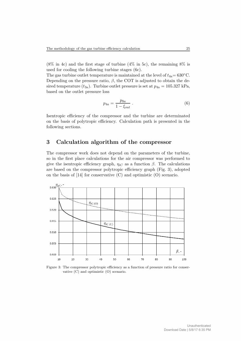
The compressor work does not depend on the parameters of the turbine,so in the first place calculations for the air compressor was performed togive the isentropic efficiency graph, ηiC as a function β. The calculationsare based on the compressor polytropic efficiency graph (Fig. 3), adoptedon the basis of [14] for conservative (C) and optimistic (O) scenario.
Figure 3: The compressor polytropic efficiency as a function of pressure ratio for conser-vative (C) and optimistic (O) scenario.
UnauthenticatedDownload Date | 5/8/17 6:35 PM

26 J. Kotowicz, M. Job, M. Brzęczek, K. Nawrat and J. Mędrych
Compressor isentropic efficiency is determined from the relationship de-scribed in [15]:
ηiC =βµC − 1
βµC
ηpC − 1
, (7)
where
µC =R
CpsC
, (8)
is the average isentropic exponent, R is the individual gas constant value,and CpsC is the average specific heat for the isentropic conversion, heredetermined from relation
CpsC =
[Cps (T1a) ln
(T1a
T0
)− Cps (T2a) ln
(T2a
T0
)]
ln(
T1a
T2a
) , (9)
where Cps (T ) is specific heat of air and its values are read for knowntemperatures (T1a and T2a), gas composition and the reference temperature(T0) from ideal gas parametric tables, e.g. [15,16].
Block diagram of the calculation algorithm for the compressor is pre-sented in Fig. 4. In a first place the compressor polytropic efficiency, ηpC ,is read from the graph (Fig. 3) for the analyzed pressure ratio, β. Based onthe Eqs. (7)–(9) isentropic efficiency of the compressor, ηiC , is calculatedwith initial assumption of Cps (T1a) = CpsC . Then, compressor outlet tem-
perature T2a and current values of CpsC and (ηiC)t are determined. Thecalculations are completed when the absolute difference between the pre-vious and the current efficiency value is less than a predefined calculationprecision, ∆ηmax. Otherwise, the next iterations of compression calcula-tions is performed for current efficiency until the predefined precision iscomplied.
The resulting characteristics of compressor isentropic efficiency are pre-sented in Fig. 5, while the compressor outlet temperature is shown in Fig. 6.It is assumed that the maximum acceptable compressor outlet temperatureis about 600 ◦C due to design restrictions. This temperature level is reachedfor pressure ratio β = 40. Thus, to apply a higher β a solution reducingthe temperature is needed, e.g., compressor with air intercooling or the useof new materials.
UnauthenticatedDownload Date | 5/8/17 6:35 PM

The methodology of the gas turbine efficiency calculation 27
Figure 4: Block diagram of the calculation algorithm for the compressor.
4 Calculation algorithm of the turbine
The next step is to calculate the turbine isentropic efficiency, ηiT , on thebasis of polytropic efficiency characteristics presented in Fig. 7, which de-pends mainly on the turbine inlet temperature and, in the second place, onthe pressure ratio.The value of β = 0 is theoretical, to actual ηpT value for assumed β isobtained by adding the corresponding value according to the relation
ηpT (β, T IT ) = ηpT (TIT, β = 0) + 0.00225β . (10)
The turbine inlet temperature is determined according to ISO-2314 stan-dard [15]. It is a theoretical temperature before the first stage stationaryblades. Simplification is here assumed that the total turbine cooling flow
UnauthenticatedDownload Date | 5/8/17 6:35 PM

28 J. Kotowicz, M. Job, M. Brzęczek, K. Nawrat and J. Mędrych
Figure 5: The compressor isentropic efficiency as a function of pressure ratio for conser-vative (C) and optimistic (O) scenario.
Figure 6: The compressor outlet temperature as a function of pressure ratio for conser-vative (C) and optimistic (O) scenario.
is mixed with the gas flow from combustor prior to entering the turbine, asillustrated in Fig. 8.
The turbine isentropic efficiency is determined from the relationship,described in detail in [15]
ηiT =1 − β−µT ηpT
1 − β−µT, (11)
UnauthenticatedDownload Date | 5/8/17 6:35 PM

The methodology of the gas turbine efficiency calculation 29
Figure 7: Turbine polytropic efficiency in function of turbine inlet temperature for β = 0for conservative (C) and optimistic (O) scenario.
Figure 8: Diagram showing the relationship between the turbine inlet temperature (TIT)and the turbine cooling air: A – the real system, B – the system accordingto [17].
where µT =R
CpsT
. (12)
The average specific heat for isentropic conversion in turbine, CpsT , is de-termined similar to (9) from relationship
CpsT =
[Cps (TIT ) ln
(T ITT0
)− Cps (T4a) ln
(T4a
T0
)]
ln(
T ITT4a
) , (13)
where Cps (T ) is specific heat of the flue gas with given composition andtemperature, read from the ideal gas parametric tables, e.g., in [15,16].
UnauthenticatedDownload Date | 5/8/17 6:35 PM

30 J. Kotowicz, M. Job, M. Brzęczek, K. Nawrat and J. Mędrych
If simplification in accordance with ISO-2314 is not applied, the cal-culation need to be done for each of the turbine stages resulting from thecooling, separately. This is caused by mixing of the flue gas with the cool-ing air, which changes the gas composition and temperature affecting itsparameters (CpsT ). Calculation of ηiT is performed iteratively according tothe algorithm illustrated in Fig. 9. For the known compressor parameters
Figure 9: Block diagram of the calculation algorithm for the turbine.
UnauthenticatedDownload Date | 5/8/17 6:35 PM

The methodology of the gas turbine efficiency calculation 31
at given β calculations for the turbine can be performed. The objective forthe turbine is constant turbine outlet temperature (t4a)est = 630 ◦C, whichmeans that initially the combustor outlet temperature, t3a, and the result-ing TIT, are unknown. Therefore, at first TIT must be determined on thebasis of preassumed t3a. For given β and initial TIT the turbine polytropicefficiency, ηpT , is read and basing on Eqs. (11)–(13) isentropic efficiency,ηiT , is calculated. Then, calculations for the turbine are performed and(t4a)est = t4a is not met, the small iteration loop is realized by adjustingt3a. After the temperature condition is fulfilled, the current values of ηpT
and ηiT are re-determined for obtained results. In analogy to the compres-sor, turbine calculations are completed when the resulted (ηiT )t precisionis met.
The obtained turbine isentropic efficiency characteristics are shown inFig. 10, while the resulted temperatures of combuster outlet and turbineinlet are shown in Fig. 11. The resulting turbine isentropic efficiency can beapplied only for the analyzed case, since they depend on TIT, T4a and fluegas composition. For new assumptions the efficiency must be recalculatedaccording to the presented algorithm (Fig. 9).
Figure 10: The turbine isentropic efficiency in as a function of pressure ratio as for con-servative (C) and optimistic (O) scenario.
UnauthenticatedDownload Date | 5/8/17 6:35 PM

32 J. Kotowicz, M. Job, M. Brzęczek, K. Nawrat and J. Mędrych
Figure 11: The temperatures of combuster outlet and turbine inlet as a function of pres-sure ratio for conservative (C) and optimistic (O) scenario.
5 Gas turbine efficiency analysis
Gross electric efficiency of the gas turbine, ηelGT.gross, is determined usingthe lower heating value, LHV , of the fuel, according to relation
ηelGT.gross =NelGT
mf LHV, (14)
while the net efficiency takes into account the gas turbine own needs
ηelGT.net =NelGT.gross − ∆NGT +NF C
mf LHV, (15)
where mf is the mass flowrate of fuel. The gas turbine own needs, ∆NGT ,are assumed to be 0.22% of the gas turbine electric power, ∆NGT , andNF C is the fuel compressor power. The resulting gross and net electricefficiency of the gas turbine in function of the pressure ratio are shown inFig. 12. Chosen characteristic parameters of the gas turbine installationfor maximum achieved efficiency are summarized in Tab. 2.
6 Conclusions
A relatively high cost of the steam turbine installation compared to thegas turbine determines the direction of the combined cycle gas turbine unit
UnauthenticatedDownload Date | 5/8/17 6:35 PM

The methodology of the gas turbine efficiency calculation 33
Figure 12: Gross and net efficiency of the gas turbine installation as a function of pressureratio for conservative (C) and optimistic (O) scenario.
Table 2: Characteristic parameters of the gas turbine installation for chosen β.
Symbol Unit Conservative scenario (C) Optimistic scenario (O)
Function max. ηelGT.gross ηelGT.net ηelGT.gross ηelGT.net
β – 76 71 87.0 82
COT ◦C 1979.2 1958.8 2034.7 2016.7
TIT ◦C 1718.9 1700.5 1768.0 1751.8
ηiT – 0.8723 0.8740 0.8748 0.8764
ηiC – 0.8480 0.8497 0.8593 0.8607
t2a◦C 779.6 759.3 807.9 790.1
ηelGT.gross – 0.4294 0.4293 0.4429 0.4428
ηelGT.net – 0.4256 0.4257 0.4385 0.4386
efficiency increase. Current barrier of net electric efficiency of the CCGTplant amounting 61% can be exceeded in the near future through the in-crease in the gas turbine efficiency, what can be realized in two ways. Thefirst concept is to use gas turbines with standard pressure ratios (about 20),with a high turbine inlet temperature at the level of 1700 ◦C (J-class tur-bines). The condition for success is the use of modern gas turbine cooling
UnauthenticatedDownload Date | 5/8/17 6:35 PM

34 J. Kotowicz, M. Job, M. Brzęczek, K. Nawrat and J. Mędrych
concepts (steam cooling) and the reduction of NOx emission. An alterna-tive solution is the use of higher pressure ratios at the level of 40–50 withlower TIT (about 1500–1550 ◦C).
The presented calculation algorithms allowed to obtain isentropic effi-ciency characteristics for the compressor and the turbine depending on thepressure ratio and the turbine inlet temperature.
The analysis revealed that the gas turbine efficiency reaches its optimumat a range of high pressure ratios (β = 70–90). However, for such high βthe compressor outlet temperature is far beyond 600 ◦C, temperature limitin the compressor. Thus, the use of such high β would require fundamentalmodifications in the compressor design, e.g., by using a two-stage compres-sor with intercooling of the compressed air. The resulting TIT values forthe pressure ratios above 40 also exceed the values in modern gas turbines.The use of such high temperatures requires a more efficient cooling of theturbine blades or the use of more durable materials.
The obtained gas turbine electric efficiency characteristics shows thatan increase of pressure ratio above 50 is not justified due to the slight in-crease in the efficiency with a significant growth of compresor outlet andturbine inlet temperatures.
Received April 2014
References
[1] Chmielniak T.: Energy Technologies. WNT, Warsaw 2008 (in Polish).
[2] Szargut J., Ziębik A.: Fundamentals of Thermal Energy. PWN, Warsaw 1998 (inPolish).
[3] Kotowicz J.: Combined Cycle Power Plants. Wydawnictwo Kaprint, Lublin 2008(in Polish).
[4] Kotowicz J., Bartela Ł.: The thermodynamic and economic optimization of agas-steam power plant by means of genetic algorithms. Rynek Energii 75(2008), 2,31–38 (in Polish).
[5] Kotowicz J., Bartela Ł.: The influence of economic parameters on the optimalvalues of the design variables of a combined cycle plant. Energy 35(2010), 2, 911–919.
[6] Kotowicz J., Job M.: Thermodynamic and economic analysis of a gas turbinecombined cycle plant with oxy-combustion. Arch. Thermodyn. 34(2013), 4, 215–233.
[7] Kotowicz J., Bartela Ł.: Analysis of operation of the gas turbine in a poligen-eration combined cycle. Arch. Thermodyn. 34(2013), 4, 137–159.
UnauthenticatedDownload Date | 5/8/17 6:35 PM

The methodology of the gas turbine efficiency calculation 35
[8] Heavy Duty Gas Turbines & Combined Cycle. General Electric. http://site.ge-energy.com/prod_serv/products/gas_turbines_cc/en/index.htm (accessed on15.04.2014).
[9] Gas turbines. Mitsubishi Heavy Industries, Ltd. http:www.mhi.co.jp/en/products/category/gas_turbin.html (accessed on 15.04.2014).
[10] Facchini B., Innocenti L., Carvnevale E.: Evaluation and comparison of dif-ferent blade cooling solutions to improve cooling efficiency and gas turbine perfor-mances. In: Proc. ASME Turbo Expo 2001, 2001-GT-0571, June 2001, New Orleans.
[11] Jordal K. et al.: New possibilities for combined cycles through advanced steam tech-nology. In: Proc. ASME Turbo Expo 2002, GT-2002-30151, June 2002, Amsterdam,The Netherlands.
[12] Hada S., Yuri M., Masada J., Ito E., Tsukagoshi K.: Evolution and futuretrend of large frame gas turbines a new 1600 degree C, J class gas turbine. In: Proc.ASME Expo 2012, GT2012-68574, June 11–15, 2012, Copenhagen.
[13] Ito E., Okada I., Tsukagoshi K., Muyama A., Masada J.: Development of keyTechnologies for next generation gas turbine. In: Proc. ASME Turbo Expo 2007:Gas Turbine Technical Congress and Exposition, GT2007-41023, May 17–20, 2007,Montreal.
[14] Wettstein H.E.: The potential of GT combined cycles for ultra high efficiency. In:Proc. ASME Turbo Expo 2012, GT2012-68586. Denmark, 2012.
[15] Chmielniak T., Rusin A., Czwiertnia K.: Gas Turbines. Ossolineum, Wrocław2001 (in Polish).
[16] Szargut J.: Thermodynamics. PWN, Warsaw 2000 (in Polish).
[17] ISO 2314:2009 Standard: Gas turbines – Acceptance tests.
UnauthenticatedDownload Date | 5/8/17 6:35 PM