the modular water chiller - chipkin automation systems master control user manual.pdf · each...
TRANSCRIPT
The Modular Water Chiller
MASTER CONTROL
USER MANUAL
MULTISTACK
CAPACITY 25% DELAY 60 CHW = 55 45 DEMAND 100% NO FAULTS CW = 85 95
LOAD PROFILE
ON/OFF STATUS
SYSTEM VARIABLES
FAULT RESET
FAULT REVIEW
COMPUT 25 WATER/AIR COOLED APPLICATION (VERSION 4.1)
MULTISTACK
1065 MAPLE AVENUE SPARTA, WI 54656
PHONE #: (608) 366-2400 FAX #: (608) 366-2450

GENERAL DESCRIPTION
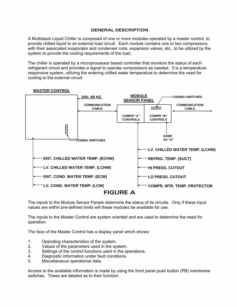
A Multistack Liquid Chiller is composed of one or more modules operated by a master control, to provide chilled liquid to an external load circuit. Each module contains one or two compressors, with their associated evaporator and condenser coils, expansion valves, etc., to be utilized by the system to provide the cooling requirements of the load. The chiller is operated by a microprocessor based controller that monitors the status of each refrigerant circuit and provides a signal to operate compressors as needed. It is a temperature responsive system, utilizing the entering chilled water temperature to determine the need for cooling to the external circuit.
FIGURE A
The inputs to the Module Sensor Panels determine the status of its circuits. Only if these input values are within pre-defined limits will these modules be available for use. The inputs to the Master Control are system oriented and are used to determine the need for operation. The face of the Master Control has a display panel which shows: 1. Operating characteristics of the system. 2. Values of the parameters used in the system. 3. Settings of the control functions used in the operations. 4. Diagnostic information under fault conditions. 5. Miscellaneous operational data. Access to the available information is made by using the front panel push button (PB) membrane switches. These are labeled as to their function.
ENT. CHILLED WATER TEMP. (ECHW) LV. CHILLED WATER TEMP. (LCHW) ENT. COND. WATER TEMP. (ECW) LV. COND. WATER TEMP. (LCW)
LV. CHILLED WATER TEMP. (LCHW) REFRIG. TEMP. (SUCT) HI PRESS. CUTOUT LO PRESS. CUTOUT COMPR. MTR. TEMP. PROTECTOR
CODING SWITCHES
CODING SWITCHES
COMMUNICATION CABLE
COMPR “A” CONTROLS
COMPR “B” CONTROLS
SAME AS “A”
24V, 60 HZ MODULE SENSOR PANEL
MASTER CONTROL
COMMUNICATION CABLE
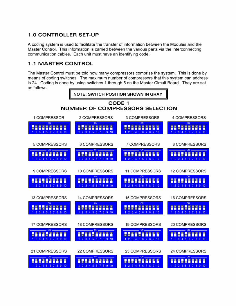
1.0 CONTROLLER SET-UP A coding system is used to facilitate the transfer of information between the Modules and the Master Control. This information is carried between the various parts via the interconnecting communication cables. Each unit must have an identifying code. 1.1 MASTER CONTROL The Master Control must be told how many compressors comprise the system. This is done by means of coding switches. The maximum number of compressors that this system can address is 24. Coding is done by using switches 1 through 5 on the Master Circuit Board. They are set as follows:
CODE 1 NUMBER OF COMPRESSORS SELECTION
1 COMPRESSOR 2 COMPRESSORS 3 COMPRESSORS 4 COMPRESSORS 5 COMPRESSORS 6 COMPRESSORS 7 COMPRESSORS 8 COMPRESSORS 9 COMPRESSORS 10 COMPRESSORS 11 COMPRESSORS 12 COMPRESSORS 13 COMPRESSORS 14 COMPRESSORS 15 COMPRESSORS 16 COMPRESSORS 17 COMPRESSORS 18 COMPRESSORS 19 COMPRESSORS 20 COMPRESSORS 21 COMPRESSORS 22 COMPRESSORS 23 COMPRESSORS 24 COMPRESSORS
1 2 3 4 5 6 7 8 9 10
ON
1 2 3 4 5 6 7 8 9 10
ON
1 2 3 4 5 6 7 8 9 10
ON
1 2 3 4 5 6 7 8 9 10
ON
1 2 3 4 5 6 7 8 9 10
ON
1 2 3 4 5 6 7 8 9 10
ON
1 2 3 4 5 6 7 8 9 10
ON
1 2 3 4 5 6 7 8 9 10
ON
1 2 3 4 5 6 7 8 9 10
ON
1 2 3 4 5 6 7 8 9 10
ON
1 2 3 4 5 6 7 8 9 10
ON
1 2 3 4 5 6 7 8 9 10
ON
1 2 3 4 5 6 7 8 9 10
ON
1 2 3 4 5 6 7 8 9 10
ON
1 2 3 4 5 6 7 8 9 10
ON
1 2 3 4 5 6 7 8 9 10
ON
1 2 3 4 5 6 7 8 9 10
ON
1 2 3 4 5 6 7 8 9 10
ON
1 2 3 4 5 6 7 8 9 10
ON
1 2 3 4 5 6 7 8 9 10
ON
1 2 3 4 5 6 7 8 9 10
ON
1 2 3 4 5 6 7 8 9 10
ON
1 2 3 4 5 6 7 8 9 10
ON
1 2 3 4 5 6 7 8 9 10
ON
NOTE: SWITCH POSITION SHOWN IN GRAY
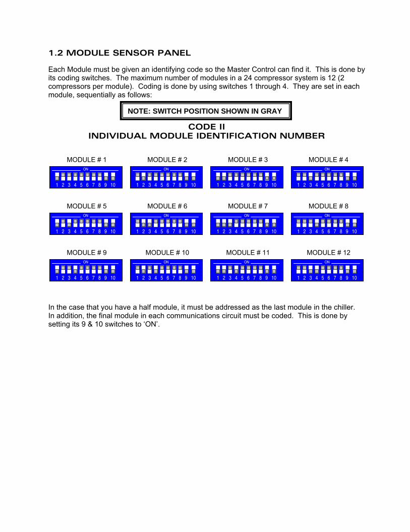
1.2 MODULE SENSOR PANEL Each Module must be given an identifying code so the Master Control can find it. This is done by its coding switches. The maximum number of modules in a 24 compressor system is 12 (2 compressors per module). Coding is done by using switches 1 through 4. They are set in each module, sequentially as follows:
CODE II INDIVIDUAL MODULE IDENTIFICATION NUMBER
MODULE # 1 MODULE # 2 MODULE # 3 MODULE # 4 MODULE # 5 MODULE # 6 MODULE # 7 MODULE # 8 MODULE # 9 MODULE # 10 MODULE # 11 MODULE # 12 In the case that you have a half module, it must be addressed as the last module in the chiller. In addition, the final module in each communications circuit must be coded. This is done by setting its 9 & 10 switches to ‘ON’.
1 2 3 4 5 6 7 8 9 10
ON
1 2 3 4 5 6 7 8 9 10
ON
1 2 3 4 5 6 7 8 9 10
ON
1 2 3 4 5 6 7 8 9 10
ON
1 2 3 4 5 6 7 8 9 10
ON
1 2 3 4 5 6 7 8 9 10
ON
1 2 3 4 5 6 7 8 9 10
ON
1 2 3 4 5 6 7 8 9 10
ON
1 2 3 4 5 6 7 8 9 10
ON
1 2 3 4 5 6 7 8 9 10
ON
1 2 3 4 5 6 7 8 9 10
ON
1 2 3 4 5 6 7 8 9 10
ON
NOTE: SWITCH POSITION SHOWN IN GRAY
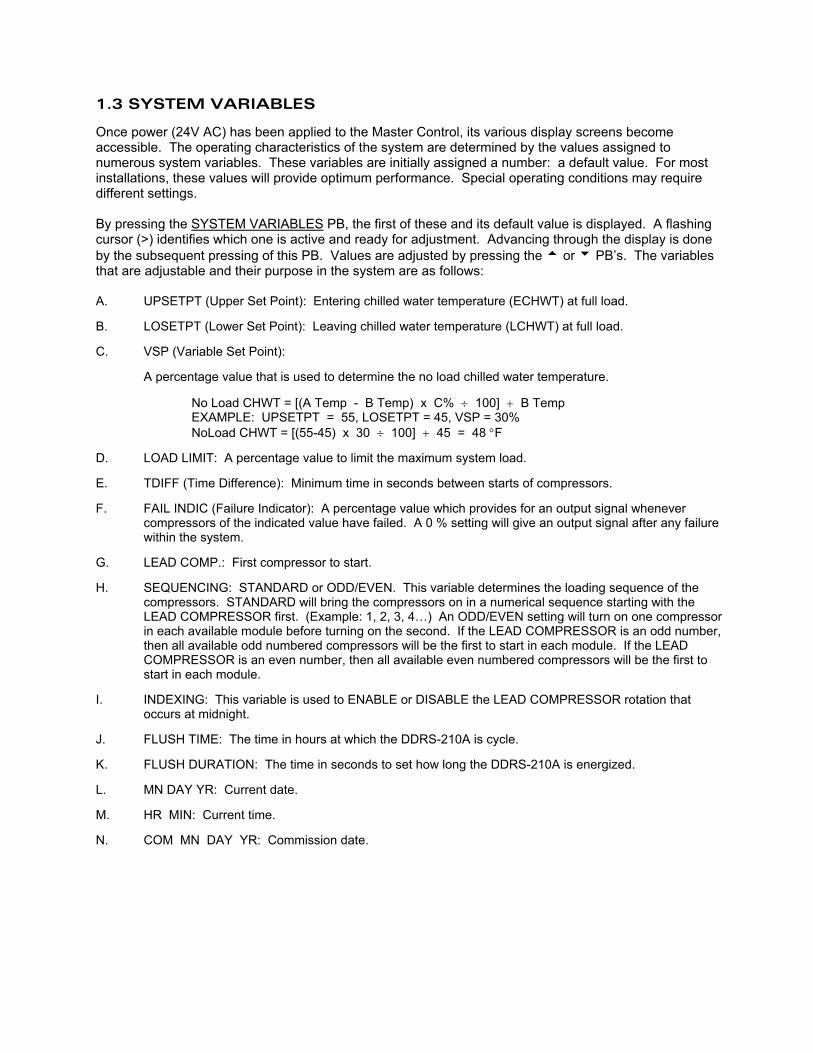
1.3 SYSTEM VARIABLES Once power (24V AC) has been applied to the Master Control, its various display screens become accessible. The operating characteristics of the system are determined by the values assigned to numerous system variables. These variables are initially assigned a number: a default value. For most installations, these values will provide optimum performance. Special operating conditions may require different settings. By pressing the SYSTEM VARIABLES PB, the first of these and its default value is displayed. A flashing cursor (>) identifies which one is active and ready for adjustment. Advancing through the display is done by the subsequent pressing of this PB. Values are adjusted by pressing the t or u PB’s. The variables that are adjustable and their purpose in the system are as follows: A. UPSETPT (Upper Set Point): Entering chilled water temperature (ECHWT) at full load. B. LOSETPT (Lower Set Point): Leaving chilled water temperature (LCHWT) at full load. C. VSP (Variable Set Point):
A percentage value that is used to determine the no load chilled water temperature. No Load CHWT = [(A Temp - B Temp) x C% ÷ 100] + B Temp EXAMPLE: UPSETPT = 55, LOSETPT = 45, VSP = 30% NoLoad CHWT = [(55-45) x 30 ÷ 100] + 45 = 48 °F D. LOAD LIMIT: A percentage value to limit the maximum system load. E. TDIFF (Time Difference): Minimum time in seconds between starts of compressors. F. FAIL INDIC (Failure Indicator): A percentage value which provides for an output signal whenever compressors of the indicated value have failed. A 0 % setting will give an output signal after any failure within the system. G. LEAD COMP.: First compressor to start. H. SEQUENCING: STANDARD or ODD/EVEN. This variable determines the loading sequence of the
compressors. STANDARD will bring the compressors on in a numerical sequence starting with the LEAD COMPRESSOR first. (Example: 1, 2, 3, 4…) An ODD/EVEN setting will turn on one compressor in each available module before turning on the second. If the LEAD COMPRESSOR is an odd number, then all available odd numbered compressors will be the first to start in each module. If the LEAD COMPRESSOR is an even number, then all available even numbered compressors will be the first to start in each module.
I. INDEXING: This variable is used to ENABLE or DISABLE the LEAD COMPRESSOR rotation that
occurs at midnight. J. FLUSH TIME: The time in hours at which the DDRS-210A is cycle. K. FLUSH DURATION: The time in seconds to set how long the DDRS-210A is energized. L. MN DAY YR: Current date. M. HR MIN: Current time. N. COM MN DAY YR: Commission date.
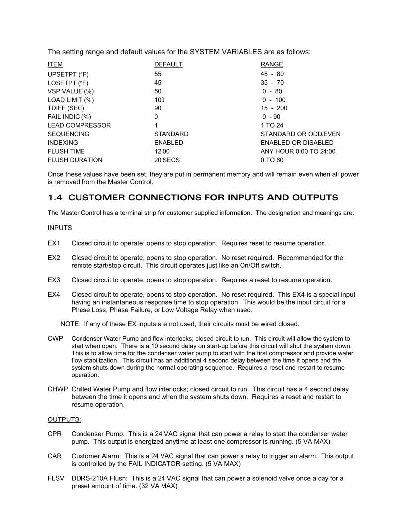
The setting range and default values for the SYSTEM VARIABLES are as follows:
ITEM DEFAULT RANGE UPSETPT (°F) 55 45 - 80 LOSETPT (°F) 45 35 - 70 VSP VALUE (%) 50 0 - 80 LOAD LIMIT (%) 100 0 - 100 TDIFF (SEC) 90 15 - 200 FAIL INDIC (%) 0 0 - 90 LEAD COMPRESSOR 1 1 TO 24 SEQUENCING STANDARD STANDARD OR ODD/EVEN INDEXING ENABLED ENABLED OR DISABLED FLUSH TIME 12:00 ANY HOUR 0:00 TO 24:00 FLUSH DURATION 20 SECS 0 TO 60
Once these values have been set, they are put in permanent memory and will remain even when all power is removed from the Master Control. 1.4 CUSTOMER CONNECTIONS FOR INPUTS AND OUTPUTS The Master Control has a terminal strip for customer supplied information. The designation and meanings are: INPUTS EX1 Closed circuit to operate; opens to stop operation. Requires reset to resume operation. EX2 Closed circuit to operate; opens to stop operation. No reset required. Recommended for the
remote start/stop circuit. This circuit operates just like an On/Off switch. EX3 Closed circuit to operate, opens to stop operation. Requires a reset to resume operation. EX4 Closed circuit to operate, opens to stop operation. No reset required. This EX4 is a special input
having an instantaneous response time to stop operation. This would be the input circuit for a Phase Loss, Phase Failure, or Low Voltage Relay when used.
NOTE: If any of these EX inputs are not used, their circuits must be wired closed. CWP Condenser Water Pump and flow interlocks; closed circuit to run. This circuit will allow the system to
start when open. There is a 10 second delay on start-up before this circuit will shut the system down. This is to allow time for the condenser water pump to start with the first compressor and provide water flow stabilization. This circuit has an additional 4 second delay between the time it opens and the system shuts down during the normal operating sequence. Requires a reset and restart to resume operation.
CHWP Chilled Water Pump and flow interlocks; closed circuit to run. This circuit has a 4 second delay
between the time it opens and when the system shuts down. Requires a reset and restart to resume operation.
OUTPUTS: CPR Condenser Pump: This is a 24 VAC signal that can power a relay to start the condenser water
pump. This output is energized anytime at least one compressor is running. (5 VA MAX) CAR Customer Alarm: This is a 24 VAC signal that can power a relay to trigger an alarm. This output
is controlled by the FAIL INDICATOR setting. (5 VA MAX) FLSV DDRS-210A Flush: This is a 24 VAC signal that can power a solenoid valve once a day for a
preset amount of time. (32 VA MAX)
2.0 OPERATIONS Having made the appropriate external connections and set the variables, the system is now ready for operation. 2.1 STARTING THE SYSTEM When power is first applied to the Master Control, the display screen shows a 12 second countdown for initializing. The display will then read ‘CHILLER OFF PRESS ON TO START’. Pushing the ON PB will display ‘30 SECOND COUNTDOWN TO START’. At the end of this delay, the first compressor will start and the display will change to the status screen. 2.2 STATUS SCREEN This provides the information on the system operation. A. CAPACITY %: How many compressors are on, compared to the total installed. B. DEMAND %: Current load compared to maximum design load. This value is determined by the system ECHWT and the settings of the variables. C. DELAY __: A time in seconds between unit happenings. D. __ FAULTS: How many faults are current. E. CHW/CW: System chilled water and condenser water entering and leaving temperature. Subsequent pressing of the STATUS PB will sequence the display through additional information screens relating to the conditions of the various modules. 2.3 STARTING OF THE COMPRESSORS Over a period of time, based on the setting of ‘TDIFF’, additional compressors will come on until all are on, or the load is satisfied. This delay time indicates the time in seconds before the next event will occur. Under pull down conditions, it will indicate when the next compressor will come on. After the last one comes on, it will count down one more time interval and then stop, indicating ‘DELAY OFF’. If something in the system prevents meeting the demand requirements, this time will continue its count until corrective action is taken. During pull down, successive compressors will start-up at intervals equal to TDIFF. As the control temperature is approached, this interval increases to 2 x TDIFF. Under conditions where the load is decreasing, compressors will shut down at intervals of 1/2 x TDIFF.
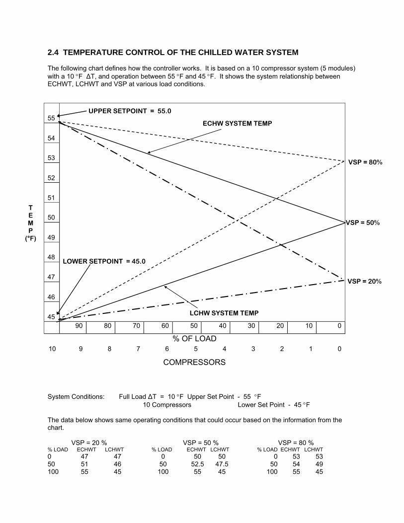
2.4 TEMPERATURE CONTROL OF THE CHILLED WATER SYSTEM The following chart defines how the controller works. It is based on a 10 compressor system (5 modules) with a 10 °F ∆T, and operation between 55 °F and 45 °F. It shows the system relationship between ECHWT, LCHWT and VSP at various load conditions.
55
54
53
52
51
50
49
48
47
46
45
90 80 70 60 50 40 30 20 10 0
% OF LOAD 10 9 8 7 6 5 4 3 2 1 0
COMPRESSORS System Conditions: Full Load ∆T = 10 °F Upper Set Point - 55 °F 10 Compressors Lower Set Point - 45 °F The data below shows same operating conditions that could occur based on the information from the chart. VSP = 20 % VSP = 50 % VSP = 80 % % LOAD ECHWT LCHWT % LOAD ECHWT LCHWT % LOAD ECHWT LCHWT 0 47 47 0 50 50 0 53 53 50 51 46 50 52.5 47.5 50 54 49 100 55 45 100 55 45 100 55 45
LOWER SETPOINT = 45.0
UPPER SETPOINT = 55.0
VSP = 50%
ECHW SYSTEM TEMP
LCHW SYSTEM TEMP
VSP = 80%
VSP = 20%
T E M P
(°F)
2.5 SHUTTING THE SYSTEM DOWN Pressing the OFF PB will return the display to ‘CHILLER ON’. Pressing again will shut everything down. 2.6 FAULTS If some abnormal operating condition were to occur in the system, the affected unit will shut down and the display will indicate what is wrong. The display will also indicate what corrective action is necessary to resume operation. Faults can be either System or Module related. MODULE FAULTS
HP: High Pressure Cutout. This requires resetting at both the HP control and the Master Control to resume operation.
LP: Low Pressure Cutout. This requires resetting at the LP control and the Master Control to resume operation.
TH: Thermal Fault. This would occur if the motor protector sensed an overload in the compressor motor. It would also occur if any component in the motor protector circuit failed open. This requires resetting at the Master Control and on some units, at the OL also.
LOSUC: Low Suction Temperature. If during operation this temperature should drop to 25 °F, the
compressor will shut down. This requires resetting at the Master Control but only after the temperature has risen to 30 °F.
LOCHW: Low Leaving Chilled Water Temperature (Below 36 °F). (Evaporator freeze protection) This
requires resetting at the Master Control but only after the temperature has risen to 40 °F. COMMUN: Communication Error between units.
SYSTEM FAULTS LOCHW: Low Leaving Chilled Water Temperature (Below 36 °F). This requires resetting at Master
Control but only after the temperature has risen to 40 °F. EX 1-4: Customer Inputs. EX1 and EX3 require resetting at the Master Control. CWP: Condenser Water Pump Circuit. This requires resetting at the Master Control. CHWP: Customer Chilled Water Pump Circuit. This requires resetting at the Master Control.
The status of faults as indicated at the Master Control can be: CURRENT: Fault is still present. Corrective action must be taken. RESET: Fault can be reset and operation resumed by pressing the Fault Reset PB. RECORD: Fault is now recorded in memory for future references. When a fault occurs, if its a system fault, the system will shut down and the display will indicate what’s wrong. If its a module fault, the appropriate module circuit will shut down and the fault will be indicated on the status screen. Interrogating the system to find out what’s wrong involves other display screens. A. STATUS: Additional information can be obtained from the status display. Pressing the STATUS PB repeatedly will display information on the individual compressors of the system until the affected compressor information is displayed. In addition to temperature information there is a status entry. The associated number is coded to faults: 1 - High Pressure 2 - Lo Pressure 4 - Therm These will only be indicated while the fault is current. B. FAULT REVIEW: Pressing the FAULT REV PB, changes the display to the fault review section. Using the 7 PB will allow scanning through the faults in memory, displaying pertinent information on each, starting with the most recent one. From this display, a reset can be done, if appropriate, by pressing the RESET PB. For each fault displayed, the circuit is identified by number as well as the type of fault. Also shown are the suction and chilled water temperatures of the circuit at the time the fault occurred. Information concerning system conditions at the time the fault occurred can be obtained by pressing the FAULT REV PB a second time. 3.0 MISCELLANEOUS CONTROL FUNCTIONS 3.1 DISPLAY LIGHT INTENSITY The lighting of the display has two levels. Normally it will be in its dim condition. Pressing any PB will brighten it and this will persist for 1 1/2 min. if left undisturbed. A display of this type, if operated in its bright mode continuously loses intensity with time. Since most of its operating life is spent in its dimmed condition, life is extended. 3.2 LOAD PROFILE Pressing the LOAD PROFILE PB will display the operating history of the system. This display relates the total operating hours to the % load and is subdivided into 10 % segments. A second display is accessed by pressing the LOAD PROFILE PB a second time. This profile data can be erased by simultaneously pressing the LOAD PROFILE and FAULT RESET PB’s.
3.3 FAULT MEMORY The maximum number of faults that are retained is 20. As more new faults are added, the oldest ones are dropped. All faults can be erased by simultaneously pressing the FAULT REVIEW and FAULT RESET PB’s. 3.4 FAULT INDICATOR In the lower left corner of the status screen is a blank space. Should the number of failed circuits equal or exceed the number established by the setting of the failure indicator, a blinking asterisk (*) will appear. A fault setting of zero requires one fault to trigger this signal. 3.5 TEMPERATURE READINGS All are a measure of actual temperatures in °F. Should a readout in °C be desirable, switch 6 in the Master Control should be ‘OFF’. The computer uses a calculated temperature of the ECHWT for control purposes. This value may be different than the actual temperature as displayed on the STATUS screen. By pressing and holding the FAULT RESET PB, this calculated value will replace the actual value that’s being displayed. 3.6 TIME AND DATE Time and Date Information is provided and accessible via the SYSTEMS VARIABLES PB. This information will be listed next to each fault in the FAULT REVIEW, and has a battery back-up in case of a power failure to the Master Control. 3.7 LEAD COMPRESSOR INDEXING Every 24 hours at midnight, the lead compressor is indexed by one unit. Any reduction in load after this time will shut the previous lead compressor down first and subsequent calls for cooling will start a new one at the other end of the assembly. This will equalize running time on all compressors over a year’s operation. This option can be either ENABLED or DISABLED in the SYSTEM VARIABLES under the listing of INDEXING. 3.8 SYSTEM VARIABLES A PB switch is installed to prevent unauthorized personnel from changing the values of the system variables. There is a hidden switch located behind the center of the MS logo, which when pressed and held for 3 seconds will lock the variables, preventing change. Unlocking of the variables adjustment requires pressing it again for 3 seconds. 3.9 WATER COOLED/AIR COOLED DISPLAY The Master Control is set-up by the factory to display system entering and leaving condenser water temperatures (CW). If your application is for an Air Cooled system, you can eliminate these readings by setting dip switch 10 in the Master Control to the ‘OFF’ position. With the sensors plugged in and dip switch 10 in the ‘OFF’ position, the display will read AUX (auxiliary) instead of CW (condenser water).
3.10 DDRS-210A OPERATION The Master Control is equipped with an output that will energize a solenoid valve. The operation of this valve is intended to be used for the DDRS-210A application. The flush time and length can be set in the SYSTEM VARIABLES screen under the headings FLUSH TIME and FLUSH DURATION. To enable this circuit, dip switch 9 in the Master Control must be ‘ON’. To manually cycle the DDRS-210A solenoid valve at any time, press and hold the hidden switch for 1 second, but less than 3 seconds. (If held for 3 seconds, the system variables will be locked or unlocked as described in 3.8 above) . NOTE: THIS OUTPUT IS RATED FOR 32 VA. USE ONLY SOLENOID VALVES SPECIFIED BY MULTISTACK. 3.11 INDICATOR LIGHTS Each electronic board has lights to aid in the system operation. A. Master Control. Along the top of the PC board are six lights. When on, they indicate normal operation. Their circuit functions are: D18 EX1 INPUT D19 EX2 INPUT D20 EX3 INPUT D21 EX4 INPUT D22 CWP INPUT D23 CHWP INPUT Near the bottom of the board are three more lights. When on, they indicate their operational function: D33 OUTPUT TO CWP D34 OUTPUT TO ALARM D35 OUTPUT TO DDRS VALVE B. Module Sensor Board. Along the right side are nine lights. When on, they indicate their operational
function: D16 THM FAULT COMP A D22 COMP A ON D17 HP FAULT COMP A D18 LP FAULT COMP A D19 THM FAULT COMP B D24 COMP B ON D20 HP FAULT COMP B D21 LP FAULT COMP B D27 ERROR D27 (ERROR), if on, will indicate that board is not communicating properly with the Master Control. Two additional lights along the bottom, when on indicate; D28 DRIVE SIGNAL FROM THE MASTER CONTROL FOR COMP A IS PRESENT D29 DRIVE SIGNAL FROM THE MASTER CONTROL FOR COMP B IS PRESENT
3.12 COMMUNICATION CABLES The Master Control has the capability of driving two communication circuits from its output connectors TB9 & TB10. The number of modules driven from each output is discretionary as long as the number does not exceed seven. These communication lines must be properly terminated at the last module in each circuit. This is done by setting the last module’s switches 9 & 10 to ‘ON’. 3.13 DELAY TIME - STATUS SCREEN The delay time indicates the time in seconds before the next event will occur. Its value is based on the setting of TDIFF. Under pull down conditions, it will indicate when the next compressor will come on. After the last one comes on, it will count down one more time interval and then stop, indicating ‘DELAY OFF’. If something in the system prevents meeting the demand requirements, this time will continue its count until corrective action is taken. During pull down, successive compressors will start-up at intervals equal to TDIFF. As the control temperature is approached, this interval increases to 2 x TDIFF. Under conditions where the load is decreasing, compressors will shut down at intervals of 1/2 x TDIFF. 4.0 OPTIONS A. LOW TEMPERATURE OPERATION
Where cooling is necessary below 40 degree F, glycol can be used, and with the proper chip selection, a temperature setting to 20 degree F is obtainable.
B. 0 -- 10 V, 4 – 20 MA. INPUTS
Where special control functions are desired to meet an application need, this customer supplied signal can adjust the programming set points as needed. Typical application would be for Load Limit Reset or Chilled Water Reset.
C. BUILDING AUTOMATION SYSTEM INTERFACE
Where the chiller is to be integrated into a building system, and monitored by the equipment of a Controls Manufacturer, internal operational information is available. Available protocols are:
BACnet over IP BACnet over Ethernet BACnet over MSTP BACnet over ARCnet
MODBUS ASCII MODBUS RTU
JOHNSON CONTROLS N2 PROTOCOL
LONWORKS
D. CHIP CUSTOMIZATION
Where special operation is required, customization of the program chip is available.
The Modular Water Chiller
COMPUT25
TROUBLESHOOTING GUIDE
JUNE 2007
MULTISTACK 1065 MAPLE AVENUE SPARTA, WI 54656
PHONE #: (608) 366-2400 FAX #: (608) 366-2450
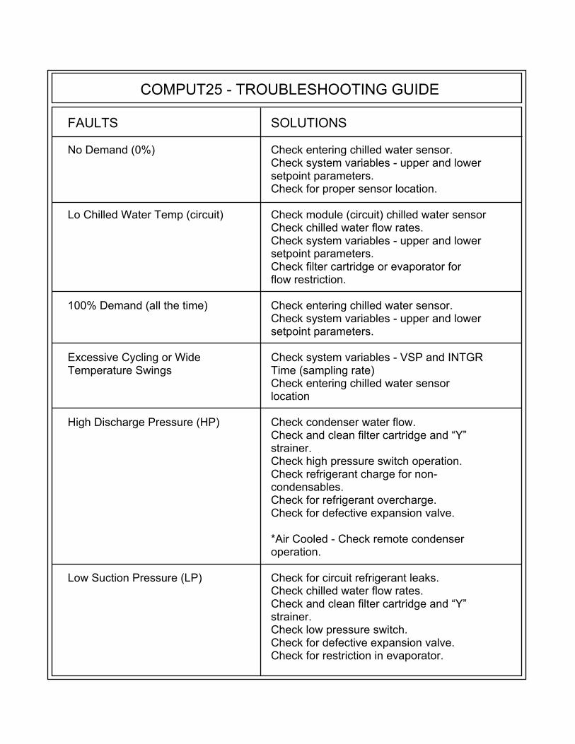
When the Multistack Chiller Control System senses conditions in either the system or in an individual refrigeration circuit which are different from, or outside the range of conditions it has been programmed to accept, it signals a “fault”. Many “faults” can have multiple causes, some internal to a single circuit, within the chiller system, or external to the chiller. The purpose of this guide is to assist qualified service technicians in diagnosing the cause, and determining action to correct the causes of the fault condition.
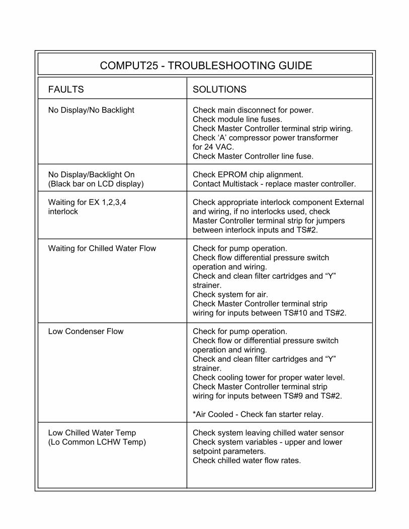
COMPUT25 - TROUBLESHOOTING GUIDE
FAULTS SOLUTIONS No Display/No Backlight Check main disconnect for power. Check module line fuses. Check Master Controller terminal strip wiring. Check ‘A’ compressor power transformer for 24 VAC. Check Master Controller line fuse. No Display/Backlight On Check EPROM chip alignment. (Black bar on LCD display) Contact Multistack - replace master controller. Waiting for EX 1,2,3,4 Check appropriate interlock component External interlock and wiring, if no interlocks used, check Master Controller terminal strip for jumpers between interlock inputs and TS#2. Waiting for Chilled Water Flow Check for pump operation. Check flow differential pressure switch operation and wiring. Check and clean filter cartridges and “Y” strainer. Check system for air. Check Master Controller terminal strip wiring for inputs between TS#10 and TS#2. Low Condenser Flow Check for pump operation. Check flow or differential pressure switch operation and wiring. Check and clean filter cartridges and “Y” strainer. Check cooling tower for proper water level. Check Master Controller terminal strip wiring for inputs between TS#9 and TS#2. *Air Cooled - Check fan starter relay. Low Chilled Water Temp Check system leaving chilled water sensor (Lo Common LCHW Temp) Check system variables - upper and lower setpoint parameters. Check chilled water flow rates.
COMPUT25 - TROUBLESHOOTING GUIDE
FAULTS SOLUTIONS No Demand (0%) Check entering chilled water sensor. Check system variables - upper and lower setpoint parameters. Check for proper sensor location. Lo Chilled Water Temp (circuit) Check module (circuit) chilled water sensor Check chilled water flow rates. Check system variables - upper and lower setpoint parameters. Check filter cartridge or evaporator for flow restriction. 100% Demand (all the time) Check entering chilled water sensor. Check system variables - upper and lower setpoint parameters. Excessive Cycling or Wide Check system variables - VSP and INTGR Temperature Swings Time (sampling rate) Check entering chilled water sensor location High Discharge Pressure (HP) Check condenser water flow. Check and clean filter cartridge and “Y” strainer. Check high pressure switch operation. Check refrigerant charge for non- condensables. Check for refrigerant overcharge. Check for defective expansion valve. *Air Cooled - Check remote condenser operation. Low Suction Pressure (LP) Check for circuit refrigerant leaks. Check chilled water flow rates. Check and clean filter cartridge and “Y” strainer. Check low pressure switch. Check for defective expansion valve. Check for restriction in evaporator.
COMPUT25 - TROUBLESHOOTING GUIDE
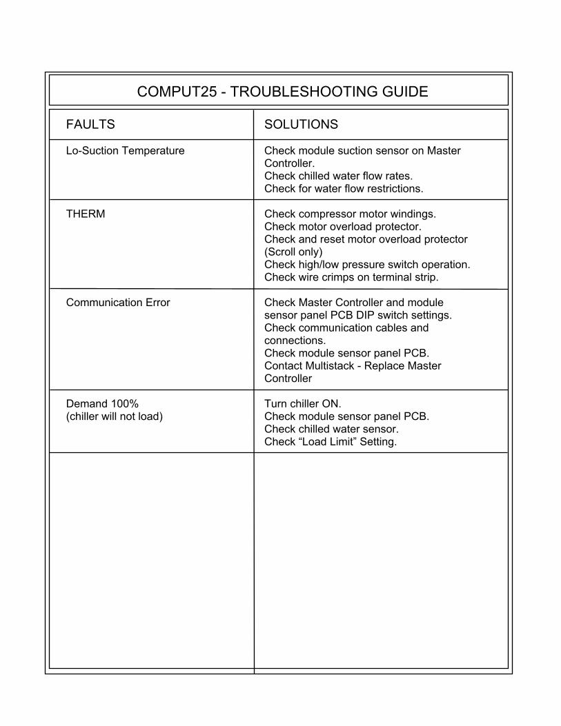
FAULTS SOLUTIONS Lo-Suction Temperature Check module suction sensor on Master Controller. Check chilled water flow rates. Check for water flow restrictions. THERM Check compressor motor windings. Check motor overload protector. Check and reset motor overload protector (Scroll only) Check high/low pressure switch operation. Check wire crimps on terminal strip. Communication Error Check Master Controller and module sensor panel PCB DIP switch settings. Check communication cables and connections. Check module sensor panel PCB. Contact Multistack - Replace Master Controller Demand 100% Turn chiller ON. (chiller will not load) Check module sensor panel PCB. Check chilled water sensor. Check “Load Limit” Setting.

USERC25_4.1.DOC
1065 MAPLE AVENUE SPARTA, WI 54656
PHONE: 608-366-2400 FAX: 608-366-2450
www.multistack.com www.airstack.com
F123 11/10/08