the most basic representation for a wave consists of a
TRANSCRIPT

IET Renewable Power Generation
Research Article
Optimal wave energy extraction for oscillatingwater columns using second-order slidingmode control
ISSN 1752-1416Received on 15th December 2019Revised 18th February 2020Accepted on 11th March 2020E-First on 9th June 2020doi: 10.1049/iet-rpg.2019.1392www.ietdl.org
F. D. Mosquera1 , C. A. Evangelista1, P. F. Puleston1, J. V. Ringwood2
1Instituto LEICI, Facultad de Ingenieria, Universidad Nacional de La Plata and CONICET, La Plata, Argentina2Department of Electronic Engineering, Centre for Ocean Energy Research, Maynooth University, Maynooth W23 F2H6, Ireland
E-mail: [email protected]
Abstract: Ocean waves are an important renewable energy resource and several fields of R&D are concurrently working toimprove technologies for harnessing their power. In that context, this study presents a control to optimise the performance ofoscillating water column systems. As a first contribution, a novel criterion to attain maximum wave energy extraction isdeveloped, resulting in an enhancement of the global power efficiency of the system. Then, taking advantage of the proposedcriterion, a second-order sliding mode control set-up is designed, with power extraction maximisation the primary objective andreactive power regulation a secondary one. Simulation results confirm the highly satisfactory performance of the proposedcontroller and its robustness in the presence of the inherent uncertainties and disturbances in the non-linear system.
1 IntroductionThe interest in clean renewable energy sources, essentially windand solar, has grown relentlessly during the last decades. Recently,the international community has been paying attention to waveenergy, which potentially would be capable of supplying aconsiderable part of the electricity demand in coastal areas [1].Different technologies are being developed to harness this energy[2, 3], typically exploiting water surface movement or pressurevariations produced below the water surface. An oscillating watercolumn (OWC) system converts wave energy into mechanicalenergy by means of a semi-submerged chamber and a self-rectifying turbine (e.g. Wells turbine) [4]. Subsequently, themechanical to electrical energy conversion is performed through avariable speed generator, for instance a double fed inductiongenerator (DFIG), which has largely proven its suitability forvariable speed operation in energy conversion applications [5–9].
Several criteria have been suggested to improve the conversionefficiency of OWC systems. In [10] and, more recently, in [7, 11],researchers have obtained very good results to increase waveenergy extraction by regulating the rotational speed, computing thereference speed to avoid turbine stall. Another interesting approachhas been introduced in [5, 12], where energy extractionenhancement is successfully achieved by operating at the flowcoefficient of maximum turbine efficiency, which results invariable rotational speed operation. Then, the novel criteriondeveloped in this paper naturally arises as a continuation of theaforementioned contributions, focusing on maximising the waveenergy extraction, by considering the mechanical system as awhole.
Of particular appeal is a control approach capable of dealingwith system uncertainties, unmodelled dynamics, externaldisturbances and non-linearities. Among the known techniques,sliding mode control (SMC) has proven to be an especially suitableapproach to cope with such challenging specifications. In fact,since its origin [13–15], SMC has evolved into a powerfultechnique to design robust controllers for a broad range of non-linear applications [16–20]. In particular, [5, 11] recently proposedfirst-order SMC schemes for OWC systems, accomplishing highlysatisfactory results. Motivated by their encouraging outcomes withfirst-order SMC, in this paper a second-order sliding mode(SOSM) control setup is developed. In years, the use of SOSM hassuccessfully widened to many different applications [16–23]. Thisfamily of controllers, among other features, presents robustness
and finite-time convergence, chattering amelioration (i.e. reductionof high-frequency oscillations of the controlled system, whichsometimes appears in certain applications of first-order SMC),simple control laws with moderately low computational cost forimplementation, and the possibility to be used in systems withrelative degree (RD) 2, as in OWC systems. Specifically, in theproposed control set-up, a Twisting and a Super-Twisting SOSMalgorithms are utilised together to fulfil the main control objectiveof maximum wave energy extraction and the secondary objectiveof reactive power regulation, respectively.
Main contributions of this paper are:
• Development of a new criterion for maximising wave energyextraction.• Application of second-order SMC to an OWC system.
The remainder of the paper is organised as follows. Section 2details the model of the complete system, comprising the OWCchamber, the Wells turbine and the DFIG. In Section 3, the novelcriterion to attain maximum wave energy extraction is derived. InSection 4, the design of the proposed SOSM control set-up ispresented. Representative simulation results are shown andanalysed in Section 5 and, finally, conclusions are drawn in Section6.
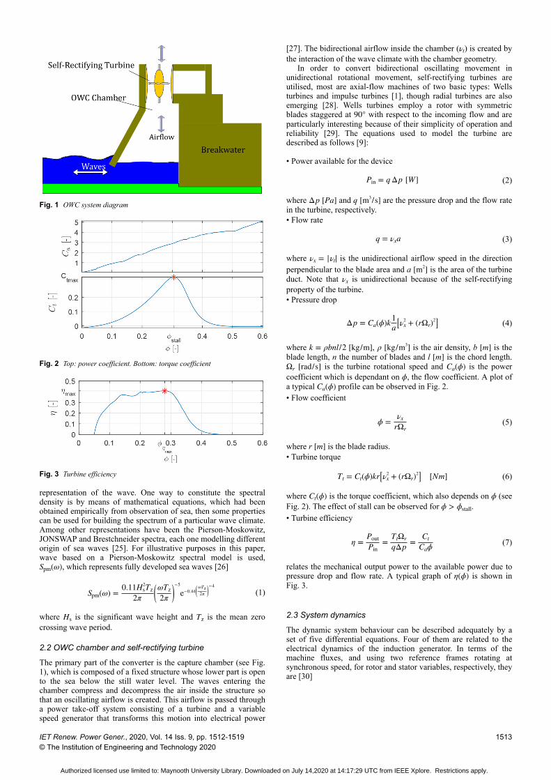
2 OWC modelThis section presents the considerations for modelling the systemunder study and the resource. A representative scheme of the OWCsystem, integrated within a breakwater, is shown in Fig. 1.
2.1 Water wave mechanics
The most basic representation for a wave consists of a sinusoidalvariation at the water surface elevation (monochromaticrepresentation). This description can be defined by means of thewave height, H, which is the vertical distances from the wave crestto the wave trough, and the wave period, T, which is the time takenfor the wave to repeat [24].
A more realistic characterisation is to consider that ocean wavesvary randomly with time, with both height and period changingevery moment. Therefore, to obtain representative attributes of awave profile, a stochastic analysis has to be done, so that the wavespectral density, S(ω), can be obtained assuming a panchromatic
IET Renew. Power Gener., 2020, Vol. 14 Iss. 9, pp. 1512-1519© The Institution of Engineering and Technology 2020
1512
Authorized licensed use limited to: Maynooth University Library. Downloaded on July 14,2020 at 14:17:29 UTC from IEEE Xplore. Restrictions apply.
representation of the wave. One way to constitute the spectraldensity is by means of mathematical equations, which had beenobtained empirically from observation of sea, then some propertiescan be used for building the spectrum of a particular wave climate.Among other representations have been the Pierson-Moskowitz,JONSWAP and Brestchneider spectra, each one modelling differentorigin of sea waves [25]. For illustrative purposes in this paper,wave based on a Pierson-Moskowitz spectral model is used,Spm(ω), which represents fully developed sea waves [26]
Spm(ω) = 0.11Hs2Tz
2πωTz2π
−5
e−0.44ωTz2π
−4(1)
where Hs is the significant wave height and Tz is the mean zerocrossing wave period.
2.2 OWC chamber and self-rectifying turbine
The primary part of the converter is the capture chamber (see Fig.1), which is composed of a fixed structure whose lower part is opento the sea below the still water level. The waves entering thechamber compress and decompress the air inside the structure sothat an oscillating airflow is created. This airflow is passed througha power take-off system consisting of a turbine and a variablespeed generator that transforms this motion into electrical power
[27]. The bidirectional airflow inside the chamber (νt) is created bythe interaction of the wave climate with the chamber geometry.
In order to convert bidirectional oscillating movement inunidirectional rotational movement, self-rectifying turbines areutilised, most are axial-flow machines of two basic types: Wellsturbines and impulse turbines [1], though radial turbines are alsoemerging [28]. Wells turbines employ a rotor with symmetricblades staggered at 90° with respect to the incoming flow and areparticularly interesting because of their simplicity of operation andreliability [29]. The equations used to model the turbine aredescribed as follows [9]:
• Power available for the device
Pin = q Δp W (2)
where Δp [Pa] and q [m3/s] are the pressure drop and the flow ratein the turbine, respectively.• Flow rate
q = νxa (3)
where νx = νt is the unidirectional airflow speed in the directionperpendicular to the blade area and a [m2] is the area of the turbineduct. Note that νx is unidirectional because of the self-rectifyingproperty of the turbine.• Pressure drop
Δp = Ca(ϕ)k 1a νx
2 + rΩr2 (4)
where k = ρbnl/2 [kg/m], ρ [kg/m3] is the air density, b [m] is theblade length, n the number of blades and l [m] is the chord length.Ωr [rad/s] is the turbine rotational speed and Ca(ϕ) is the powercoefficient which is dependant on ϕ, the flow coefficient. A plot ofa typical Ca(ϕ) profile can be observed in Fig. 2.• Flow coefficient
ϕ = νxrΩr
(5)
where r [m] is the blade radius.• Turbine torque
Tt = Ct(ϕ)kr νx2 + rΩr
2 [Nm] (6)
where Ct(ϕ) is the torque coefficient, which also depends on ϕ (seeFig. 2). The effect of stall can be observed for ϕ > ϕstall.• Turbine efficiency
η = PoutPin
= TtΩrqΔp = Ct
Caϕ(7)
relates the mechanical output power to the available power due topressure drop and flow rate. A typical graph of η(ϕ) is shown inFig. 3.
2.3 System dynamics
The dynamic system behaviour can be described adequately by aset of five differential equations. Four of them are related to theelectrical dynamics of the induction generator. In terms of themachine fluxes, and using two reference frames rotating atsynchronous speed, for rotor and stator variables, respectively, theyare [30]
Fig. 1 OWC system diagram
Fig. 2 Top: power coefficient. Bottom: torque coefficient
Fig. 3 Turbine efficiency
IET Renew. Power Gener., 2020, Vol. 14 Iss. 9, pp. 1512-1519© The Institution of Engineering and Technology 2020
1513
Authorized licensed use limited to: Maynooth University Library. Downloaded on July 14,2020 at 14:17:29 UTC from IEEE Xplore. Restrictions apply.

ψ̇ds = vds − Rsids + ωsψqs
ψ̇qs = vqs − Rsiqs − ωsψds
ψ̇dr = vdr − Rridr + (ωs − p Ωr)ψqr
ψ̇qr = vqr − Rriqr − (ωs − p Ωr)ψdr
(8)
together with the following algebraic relations:
ψds = Lsids + Lmidr
ψqs = Lsiqs + Lmiqr
ψdr = Lridr + Lmids
ψqr = Lriqr + Lmiqs
(9)
where the state variables ψqs, ψds, ψqr and ψdr represent the direct(d) and quadrature (q) flux components for stator and rotor, vqs, vds,vqr and vdr (iqs, ids, iqr and idr) are the components of the voltages(currents). Also, Rs and Rr are the electric resistance of stator androtor windings, respectively, Ls and Lr are the self-inductance of therespective windings, and Lm is the mutual inductance between thestator and rotor windings. p is the number of pole pairs andωs = 2π f s is the synchronous frequency, where f s is the gridfrequency.
The mechanical dynamics are described by
JΩ̇r = Tt − Te (10)
where J represents the inertia of the rotating parts, Tt is the turbinetorque (6) and Te is the generator torque, given by
Te = − 32 pLm idriqs − iqrids (11)
where a negative sign is added in order to have a positive torquewhen the machine is working as a generator. Finally, the statorreactive power, Qs, is
Qs = 32 vqsids − vdsiqs (12)
3 Proposed criterion for maximum wave energyextractionA new criterion is presented in this section, developed by theauthors to establish an optimum reference for the rotational speed,in order to achieve mechanical output power maximisation.
The criterion is obtained by expressing the power extracted bythe Wells turbine as a product of two factors, one of themdepending only on the wave, i.e. the external energy source, andthe other a function of the flow coefficient. From (7), and using(2)–(4), the mechanical power in the turbine shaft can be written as
Pout = ηPin = η(ϕ)Ca(ϕ) ka νx
2 + rΩr2 νxa (13)
Note that νx is an external variable, which is a function of thewave climate and the geometric characteristics of the OWCchamber, and independent of the rotational speed or any other statevariable of the turbine [31]. Following some algebraicmanipulation, the output power can be expressed as
Pout = 2kρaη(ϕ)Ca(ϕ) 1 + ϕ−2
CPf (ϕ)
ρa2 νx
3
P f
= CP f(ϕ)P f (νx) (14)
where CP f is a dimensionless, non-linear function of ϕ, that relatesthe extracted power, Pout, to a fictitious power P f , defined incorrespondence with the kinetic power developed by the airflowpassing through an area a at speed νx. Fig. 4 shows the graph of the
CP f(ϕ) coefficient corresponding to the power coefficient Ca(ϕ)and the turbine efficiency η(ϕ) shown in Figs. 2 and 3.
Remark 1: It can be seen that CP f(ϕ) has a single maximum, at
ϕ = ϕopt. Therefore, according to (14), the proposed criterion tomaximise the power extracted by the turbine is to operate thesystem at ϕ = ϕopt.
Thus, the strategy is based on controlling the rotational speed sothat this optimum condition is maintained for the varying input νxand, to this end, an optimum speed reference is defined as
Ωopt = νxrϕopt
(15)
4 SOSM controllers designFor this paper, the proposal is to accomplish two control objectivessimultaneously. The main one is the maximisation of wave powerextraction, in accordance with the criterion elaborated in Section 3.The secondary, but also important, objective focuses on reactivepower control. A schematic representation of the controlled systemis presented in Fig. 5.
As stated in the Introduction, the distinctive features of theSOSM techniques, applied to control electromechanical systems,make them an excellent choice for the system under study.Specifically, SOSM control defines a function of the system states,the so-called sliding variable σ, so that the control objectives areachieved when σ = σ̇ = 0. Such a condition defines the slidingsurface in the state space, and SOSM algorithms are designed sothat the system trajectories converge to it in finite time and robustlyremain there, even in the presence of certain disturbances anduncertainties considered during the design stage [32–34].
The steps for the design of the OWC system SOSM controlsetup are addressed in the following subsection.
4.1 OWC system reduced model for the control design
Firstly, for designing purposes, a reduced order model of thesystem is presented, which is simpler while still retaining theessential system characteristics [8]
Fig. 4 Coefficient CP f(ϕ)
Fig. 5 Schematic diagram of the controlled system
1514 IET Renew. Power Gener., 2020, Vol. 14 Iss. 9, pp. 1512-1519© The Institution of Engineering and Technology 2020
Authorized licensed use limited to: Maynooth University Library. Downloaded on July 14,2020 at 14:17:29 UTC from IEEE Xplore. Restrictions apply.

i̇qr = LsLeq
vqr − Rriqr − idr + LmVsωsLeq
ωs − pΩr
i̇dr = LsLeq
vdr − Rridr + iqr ωs − pΩr
Ω̇r = 1J Tt(ν, Ωr) − 3pLmVs
2ωsLsiqr
(16)
where Vs is the grid phase voltage and Leq = LsLr − Lm2 . The rotor
fluxes are related to the rotor currents via
ψqr = LeqLs
iqr; ψdr = LeqLs
idr + LmVsωsLs
(17)
and stator currents can be calculated as
iqs = − LmLs
iqr; ids = VsωsLs
− LmLs
idr (18)
For the reduced model, the stator reactive power and thegenerator torque can be expressed as
Qs = 3pVs2
2ωsLs− 3pLmVs
2Lsidr (19)
Te = 32
pLmVsωsLs
iqr (20)
4.2 Selection of the sliding variables
Considering the structure of the reduced dynamic model, togetherwith both desired goals, a selection of two sliding variables can beproposed which are input–output decoupled, i.e. each of the twocontrol input components directly affects only one of the twosliding variables and not the other. Thus, from the SOSM designviewpoint, the control problem can be treated as two separatedSISO systems.
4.2.1 Primary objective. Wave power extractionmaximisation: A sliding variable σ1 is defined in this section tomaximise the energy extracted from the waves by the OWCsystem, to be achieved by tracking the optimal reference (15),derived in Section 3.
Evidently, from a theoretical perspective, the best result wouldbe obtained if the flow coefficient were permanently kept at theoptimum value ϕopt for all νx (i.e. Ωref = Ωopt(νx)). However, thiswould be impractical, given that it would periodically force theturbine to stop, which is mechanically undesirable.
To avoid this behaviour, a sub-optimal solution is implemented,defining a piecewise reference limited by a minimum-speedthreshold, Ωrmin
Ωref =Ωopt(νx) = νx
rϕopt, if Ωopt(νx) > Ωrmin
Ωrmin, if Ωopt(νx) ≤ Ωrmin
(21)
According to (21), the sliding variable for the first controlobjective is defined as
σ1 = Ωref − Ωr (22)
4.2.2 Secondary objective. Reactive power regulation: Thesecond sliding variable, σ2, is defined so that the stator reactivepower tracks an external reference Qref(t). Then, using (19)
σ2 = Qref − Qs = Qref − 3pVs2
2ωsLs+ 3pLmVs
2Lsidr (23)
4.3 Design of the SOSM controllers
It is straightforward to determine that σ1 is of RD 2 with respect tovqr (not depending on vdr up to the second derivative, σ̈1), while σ2
is of RD 1 with respect to vdr (not depending on vqr up to the firstderivative, σ̇2). Then, two different SOSM algorithms, Twisting andSuper-Twisting, suitable for RD 2 and RD 1 systems, respectively,have been chosen.
4.3.1 Wave power extraction maximisation controller: Thefollowing two-term vqr control action is proposed to robustly fulfilthe primary control objective
vqr = vqrE + vqrT (24)
The first term, vqrE, is a continuous ‘bias’ control action designed tosteer the system to the neighbourhood of σ1 = 0. The second term,vqrT, is the SOSM Twisting control action, which providesrobustness to uncertainties and disturbances. Note that vqrE hasbeen included to reduce the control effort demanded by the SOSMaction. Its presence results in the design of smaller gains for theSOSM controller (hence, lesser discontinuous action andchattering), while still ensuring the existence of a robust slidingmode regime.
Firstly, the ‘bias’ control term vqrE is derived following aprocedure inspired by the equivalent control concept in SMCsystems. The RD 2 sliding variable σ1 is differentiated until thecontrol vqr explicitly appears
σ̈1 = Ω̈ref − Tt˙
J + 1J
3pLmVs2ωsLs
Rriqr + ψdr ws − pΩr
a1(x, t)
+ 1J
3pLmVs2ωeLeqb1(x, t)
vqr = a1(x, t) + b1(x, t)vqr
(25)
where x = [iqr; idr; Ωr] denotes the states. Then, the expression ofvqrE can be easily obtained from (25), as the continuous control thatensures σ1 = σ̇1 = σ̈1 = 0
vqrE = vqr σ1 = σ1̇ = σ̈1 = 0= − a1(x, t)
b1(x, t) σ1 = σ1̇ = σ̈1 = 0(26)
assuming that the system is undisturbed, i.e. neither uncertaintiesnor unknown disturbances exist.
Secondly, the SOSM Twisting control term, of the form [35]
vqrT(σ1) = − r sign(σ1) − r′ sign(σ̇1), r > r′ > 0, (27)
is designed.To tune the control gains r and r′ in accordance with the
Twisting algorithm procedure, σ̈1 needs to be explicitly written interms of the SOSM control vqrT in the general form
σ̈1 = λ1(x, t) + γ1(x, t)vqrT . (28)
Hence, substituting (24) into (25) gives
σ1¨ = a1(x, t) + b1(x, t)vqrE
λ1(x, t)
+ b1(x, t)γ1(x, t)
vqrT (29)
Then, functions λ1(x, t) and γ1(x, t) must be bounded with threepositive constants Γm1 < ΓM1 and C1, that satisfy
λ1(x, t) ≤ C1
Γm1 ≤ γ1(x, t) ≤ ΓM1(30)
IET Renew. Power Gener., 2020, Vol. 14 Iss. 9, pp. 1512-1519© The Institution of Engineering and Technology 2020
1515
Authorized licensed use limited to: Maynooth University Library. Downloaded on July 14,2020 at 14:17:29 UTC from IEEE Xplore. Restrictions apply.

Note that, to attain robust performance, the disturbances anduncertainties should be contained within these bounds. Finally, thegains must be chosen according to the following sufficientconditions to guarantee finite time convergence to σ1 = σ1˙ = 0
r = r′ + ΔT
r′ >ΔT ΓM1 − Γm1 + 2C1
2Γm1
ΔT > C1
Γm1
(31)
4.3.2 Reactive power regulation controller: To robustlyaccomplish the secondary objective of reactive power regulation, atwo-term control law is proposed as well
vdr = vdrE + vdrST, (32)
comprising a smooth ‘bias’ control term vdrE and a SOSM Super-Twisting term vdrST. The Super-Twisting algorithm was chosenbecause it can be directly applied to the RD 1 sliding variable σ2.Additionally, it provides a continuous control action (which furtherimproves the chattering amelioration) and does not rely onknowledge of σ̇2. A procedure, analogous to the one utilised in theprevious case, is followed to obtain the control terms, bearing inmind that σ2 is of RD 1 instead of 2.
Firstly, the ‘bias’ control vdrE is computed. In this case, thecontrol action vdr explicitly appears in the first time derivative of σ2
σ̇2 = Q̇ref − 3pVsLm2ωsLeq
Rridr − ψqr ωs − pΩr
A2(x, t)
+
+ 3pVsLm2ωsLeqB2(x, t)
vdr = A2(x, t) + B2(x, t)vdr,(33)
and, from (33), the smooth control vdrE that guarantees σ2 = σ̇2 = 0results in the form
vdrE = vdr σ2 = σ2̇ = 0= − A2(x, t)
B2(x, t) σ2 = σ2̇ = 0(34)
considering the undisturbed, or nominal, system.Secondly, the robust SOSM Super-Twisting term vdrST is
introduced [35]
vdrST(σ2) = − β σ2
12
sign(σ2) − α∫0
tsign(σ2(τ))dτ (35)
where β and α are the control gains.The tuning of the Super-Twisting gains requires σ̈2 to be
expressed explicitly in terms of v̇drST as
σ̈2 = λ2(x, vqr, vdr, t) + γ2(x, t)v̇drST . (36)
Consequently, differentiating the σ2 twice
σ̈2 = Q̈ref − 3pLmVs2wsLeq
ddt Rridr − ψqr ωs − pΩr
a2(x, vqr, vdr, t)
+ 3pVsLm2ωsLeqb2(x, t)
v̇dr = a2(x, vqr, vdr, t) + b2(x, t)v̇dr
(37)
and substituting (32) into (37), it gives
σ2¨ = a2(x, vqr, vdr, t) + b2(x, t)v̇drE
λ2(x, vqr, vdr, t)
+ b2(x, t)γ2(x, t)
v̇drST (38)
as required in (36).To complete the Super-Twisting design procedure, functions
λ2(x, vqr, vdr, t) and γ2(x, t) must be bounded with three positiveconstants Γm2 < ΓM2 and C2 such that
λ2(x, vqr, vdr, t) ≤ C2
Γm2 ≤ γ2(x, t) ≤ ΓM2,(39)
taking into account the disturbances and uncertainty bounds.Finally, if the gains are selected so that they verify the sufficient
conditions
α > C2
Γm2
β >2 αΓM2 + C2
Γm2,
(40)
then, finite-time convergence to σ2 = σ2˙ = 0 and robust SOSMoperation are guaranteed, even in the presence of disturbances anduncertainties considered in the computation of the bounds.
5 Simulations resultsThe results obtained with the new criterion for maximum waveenergy extraction, together with the proposed SOSM controlsetups, are presented and analysed in this section in tworepresentative cases. In case study 1, a realisation of apanchromatic wave with Pierson-Moskowitz spectrum was utilisedto assess the controller's behaviour under a realistic wave climate.In case study 2, the maximum wave energy extraction criterionproposed is contrasted with other criteria for energy extraction,using a train of perturbed monochromatic waves which allows aclear comparison.
To test the controllers under practical conditions, thesimulations are conducted utilising the full order model of theOWC system (8)–(12), incorporating uncertainties up to 15% withrespect to the electrical and aerodynamic parameters. Theparameters of the Wells turbine, chamber and the 7.5 kW DFIGgenerator are shown in Table 1.
The disturbed model was considered to compute the boundingconstants in (30) and (39). Practical bounds were obtained throughexhaustive analysis under realistic conditions of operation andassisted by comprehensive computer simulations. After furtherheuristic refinement, the following gains, suitable for practical use,have been set for the controllers:
r = 20; r′ = 10α = 596.5; β = 3.88
5.1 Case study 1: irregular waves
The present case considers the use of a Pierson-Mozkowitzspectrum with Hs = 0.9 m and Tz = 12 s, which models a realisticwave climate. Thus, the simulations presented herein correspond tothe ariflow profile shown in Fig. 6.
Table 1 System parametersTurbine and chamber Generatorn = 5 p = 1 Rr = 0.2305 Ωl = 0.165 m Jg = 0.07 kg m2 Ls = 1.7 mHyb = 0.21 m P = 7.5 kW Lr = 2.4 mHyr = 0.375 m Vrms = 400 Vrms Lm = 76.6 mHylc = 4.3 m f s = 50 Hzw = 4.5 m ωs = 2π f s rad/sJp = 0.44 kg m2 Rs = 0.2702 Ω
1516 IET Renew. Power Gener., 2020, Vol. 14 Iss. 9, pp. 1512-1519© The Institution of Engineering and Technology 2020
Authorized licensed use limited to: Maynooth University Library. Downloaded on July 14,2020 at 14:17:29 UTC from IEEE Xplore. Restrictions apply.
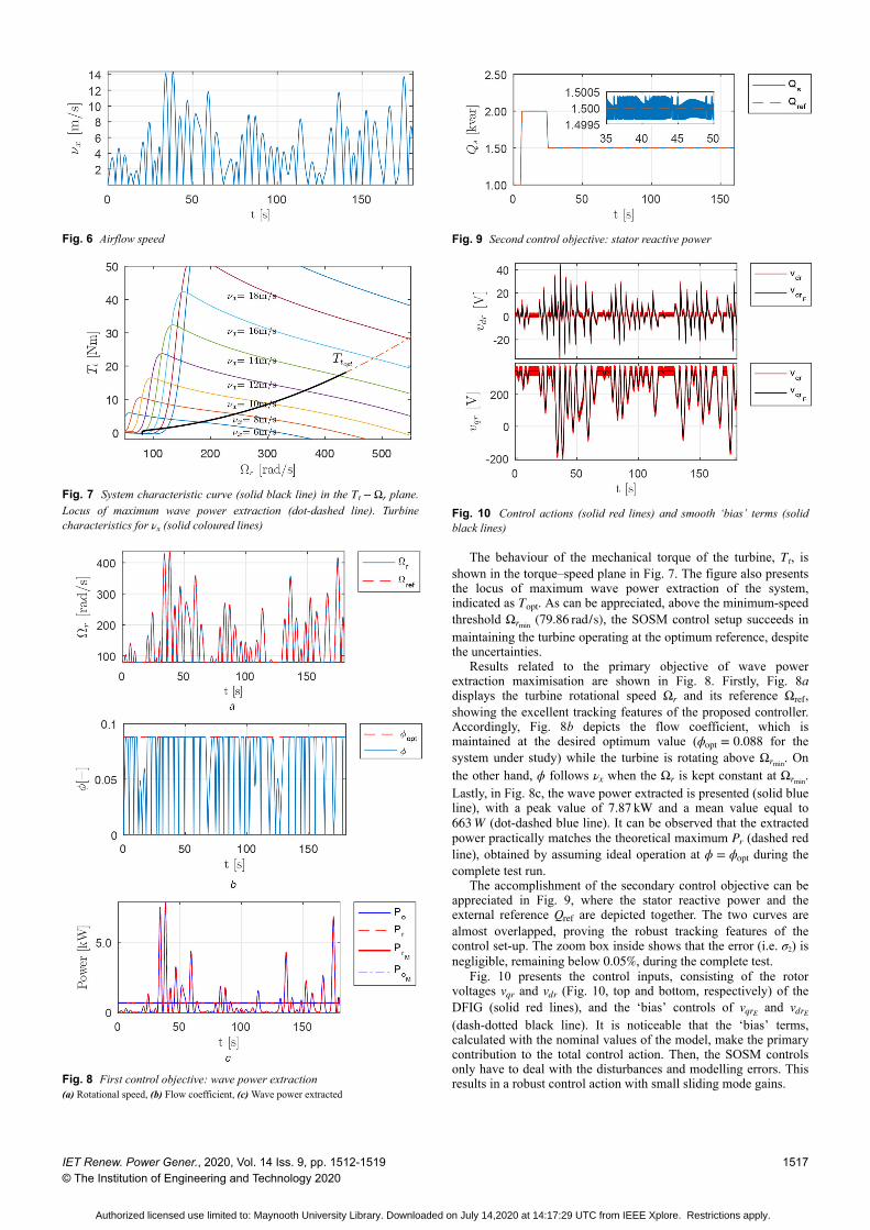
The behaviour of the mechanical torque of the turbine, Tt, isshown in the torque–speed plane in Fig. 7. The figure also presentsthe locus of maximum wave power extraction of the system,indicated as Topt. As can be appreciated, above the minimum-speedthreshold Ωrmin (79.86 rad/s), the SOSM control setup succeeds inmaintaining the turbine operating at the optimum reference, despitethe uncertainties.
Results related to the primary objective of wave powerextraction maximisation are shown in Fig. 8. Firstly, Fig. 8adisplays the turbine rotational speed Ωr and its reference Ωref,showing the excellent tracking features of the proposed controller.Accordingly, Fig. 8b depicts the flow coefficient, which ismaintained at the desired optimum value (ϕopt = 0.088 for thesystem under study) while the turbine is rotating above Ωrmin. Onthe other hand, ϕ follows νx when the Ωr is kept constant at Ωrmin.Lastly, in Fig. 8c, the wave power extracted is presented (solid blueline), with a peak value of 7.87 kW and a mean value equal to663 W (dot-dashed blue line). It can be observed that the extractedpower practically matches the theoretical maximum Pr (dashed redline), obtained by assuming ideal operation at ϕ = ϕopt during thecomplete test run.
The accomplishment of the secondary control objective can beappreciated in Fig. 9, where the stator reactive power and theexternal reference Qref are depicted together. The two curves arealmost overlapped, proving the robust tracking features of thecontrol set-up. The zoom box inside shows that the error (i.e. σ2) isnegligible, remaining below 0.05%, during the complete test.
Fig. 10 presents the control inputs, consisting of the rotorvoltages vqr and vdr (Fig. 10, top and bottom, respectively) of theDFIG (solid red lines), and the ‘bias’ controls of vqrE and vdrE
(dash-dotted black line). It is noticeable that the ‘bias’ terms,calculated with the nominal values of the model, make the primarycontribution to the total control action. Then, the SOSM controlsonly have to deal with the disturbances and modelling errors. Thisresults in a robust control action with small sliding mode gains.
Fig. 6 Airflow speed
Fig. 7 System characteristic curve (solid black line) in the Tt − Ωr plane.Locus of maximum wave power extraction (dot-dashed line). Turbinecharacteristics for νx (solid coloured lines)
Fig. 8 First control objective: wave power extraction(a) Rotational speed, (b) Flow coefficient, (c) Wave power extracted
Fig. 9 Second control objective: stator reactive power
Fig. 10 Control actions (solid red lines) and smooth ‘bias’ terms (solidblack lines)
IET Renew. Power Gener., 2020, Vol. 14 Iss. 9, pp. 1512-1519© The Institution of Engineering and Technology 2020
1517
Authorized licensed use limited to: Maynooth University Library. Downloaded on July 14,2020 at 14:17:29 UTC from IEEE Xplore. Restrictions apply.

5.2 Case study 2: regular waves
In this case, a comparison between the proposed control criterionand two previous reported comparable criteria [5, 11] is displayed.For a clear visualisation of the comparison results, a wave profilecomposed of two consecutive trains of perturbed monochromaticwaves has been used. The first half of the wave signal has a meanwave period of T = 12 s, and a mean wave height of H = 1 m.After a transition, at t = 30 s, the mean wave height is increased,resulting into a 40% airflow amplitude increase (as depicted in Fig.11).
For the sake of illustration, the extracted power (Pout) obtainedwith the novel criterion proposed in Section 3, is depicted in Fig.12, together with the ones obtained with the two reference criteria. The first one, Criterion 1 (solid red line), proposes operation atmaximum turbine efficiency (eq. (7), Fig. 3), which isaccomplished by maintaining the flow coefficient constant atϕ = ϕηmax = 0.29 (for the system under study). The second one,Criterion 2 (solid green line), aims to increase wave energyextraction by regulating the rotational speed to avoid turbine stall.To this end, the reference speed is computed in accordance withϕstall = 0.3 (see Fig. 2) and two different values of Ωref, 105.19 and124.32 rad/s, respectively, for the two portions of the simulationinterval. It should be noted that, due to the lower rotational speedranges of criteria 1 and 2, a DFIG with two pairs of poles (p = 2)was used for the corresponding tests.
Finally, the electrical energy delivered to the grid by eachcriterion is shown in Fig. 13. To illustrate, a period of 10 min,which comprises several wave cycles, has been depicted.
6 ConclusionsTwo main conclusions can be drawn from this work. The first oneis that to increase power extraction from the waves, it is necessaryto approach the OWC system as a whole. In this sense, excellentresults have been obtained with the novel criterion introduced inthe paper. The underlaying rationale for its development, was toexpress the power extracted by the turbine as a product of twofactors, one depending only on the wave (external energy source)and the other a function of the flow coefficient (a system variable).In this way, wave energy maximisation is reduced to a very simpleobjective, to operate at the flow coefficient that maximises theextracted power. It should be added that the control objective,shaped in accordance with the proposed criterion, not onlyappropriate with SMC, but also with other different controltechniques of interest.
The second noteworthy conclusion is that it has been shownthat SOSM techniques are especially suitable to tackle the controlchallenges presented by OWC systems. In effect, highly successfulsimulation results have been achieved with the SOSM controlsetups designed in this paper. Based on the Twisting and Super-Twisting algorithms, the objectives of wave power extractionmaximisation and reactive power regulation have been robustlyattained, even in a non-linear system with uncertainties and anextremely varying input, as a typical wave train is.
7 AcknowledgmentThis work has been supported by the Universidad Nacional de LaPlata, the CONICET and the Agencia Nacional de PromociónCientífica y Tecnológica (ANPCyT) from Argentina. This workwas partially supported by Science Foundation Ireland under grantno. SFI/13/IA/1886 and grant no. 12/RC/2302 for the MaREICentre for Marine and Renewable Energy.
8 References[1] Falcao, A.F.O., Henriques, J.C.C.: ‘Oscillating-water-column wave energy
converters and air turbines: a review’, Renew. Energy, 2016, 85, pp. 1391–1424
[2] Korde, U.A., Ringwood, J.V.: ‘Hydrodynamic control of wave energy devices’(Cambridge University Press, Cambridge, 2016)
[3] Ceballos, S., Rea, J., Lopez, I., et al.: ‘Efficiency optimization in low inertiawells turbine-oscillating water column devices’, IEEE Trans. EnergyConvers., 2013, 28, (3), pp. 553–564
[4] Falcao, A.F.O., Henriques, J.C.C., Gato, L.M.C.: ‘Rotational speed controland electrical rated power of an oscillating-water-column wave energyconverter’, Energy, 2017, 120, pp. 253–261
[5] Barambones, O., Cortajarena, J.A., Gonzalez de Durana, J.M., et al.: ‘A realtime sliding mode control for a wave energy converter based on a wellsturbine’, Ocean Eng., 2018, 163, pp. 275–287
[6] M'zoughi, F., Bouallègue, S., Garrido, A.J., et al.: ‘Stalling-free controlstrategies for oscillating-water-column-based wave power generation plants’,IEEE Trans. Energy Convers., 2018, 33, (1), pp. 209–222
[7] Mishra, S.K., Purwar, S., Kishor, N.: ‘An optimal and non-linear speedcontrol of oscillating water column wave energy plant with wells turbine andDFIG’, Int. J. Renew. Energy Res., 2016, 6, (3), pp. 995–1006
[8] Beltran, B., Benbouzid, M.E.H., Ahmed-Ali, T.: ‘Second-order sliding modecontrol of a doubly fed induction generator driven wind turbine’, IEEE Trans.Energy Convers., 2012, 27, (2), pp. 261–269
[9] Alberdi, M., Amundarain, M., Garrido, A.J., et al.: ‘Complementary controlof oscillating water column-based wave energy conversion plants to improvethe instantaneous power output’, IEEE Trans. Energy Convers., 2011, 26, (4),pp. 1021–1032
[10] Amundarain, M., Alberdi, M., Garrido, A.J., et al.: ‘Modeling and simulationof wave energy generation plants: output power control’, IEEE Trans. Ind.Electron., 2011, 58, (1), pp. 105–117
[11] Garrido, A.J., Garrido, I., Amundarain, M., et al.: ‘Sliding-mode control ofwave power generation plants’, IEEE Trans. Ind. Appl., 2012, 48, (6), pp.2372–2381
[12] Barambones, O., Gonzalez de Durana, J., Calvo, I.: ‘Adaptive sliding modecontrol for a double fed induction generator used in an oscillating watercolumn system’, Energies, 2018, 11, (11), p. 2939
[13] Utkin, V.I.: ‘Variable structure systems with sliding modes’, IEEE Trans.Autom. Control, 1977, 22, (2), pp. 212–222
[14] Utkin, V.I., Gulder, J., Shi, J.: ‘Sliding mode control in electro-mechanicalsystems’ (Taylor and Francis, London, 1999)
[15] Sira-Ramirez, H.On the dynamical sliding mode control of nolinear systems',Int. J. Control., 1993, 57, (5), pp. 1039–1061
[16] Bartolini, G., Fridman, L., Pisano, A., et al.: ‘Modern sliding Mode controltheory’. Lecture Notes in Control and Information Sciences, vol. 375,(Springer, Berlin, Heidelberg, 2008)
[17] Fridman, L., Moreno, J., Iriarte, R., et al.: ‘Sliding modes after the firstdecade of the 21st century’. Lecture Notes in Control and InformationSciences, vol. 412, (Springer, Berlin Heidelberg, 2012)
Fig. 11 Airflow speed
Fig. 12 Wave extracted power with different criteria
Fig. 13 Electrical energy generated in 10 min
1518 IET Renew. Power Gener., 2020, Vol. 14 Iss. 9, pp. 1512-1519© The Institution of Engineering and Technology 2020
Authorized licensed use limited to: Maynooth University Library. Downloaded on July 14,2020 at 14:17:29 UTC from IEEE Xplore. Restrictions apply.

[18] Bandyopadhyay, B., Janardhanan, S., Spurgeon, S.K., et al.: ‘Advances insliding mode control’. Lecture Notes in Control and Information Sciences,vol. 440, (Springer, Berlin Heidelberg, 2013)
[19] Barbot, J.P., Plestan, F., Fridman, L. (Eds.): ‘Recent trends in sliding modecontrol’ (Institution of Engineering and Technology, United Kingdom, 2016)
[20] Li, S., Yu, X., Fridman, L., et al.: ‘Advances in variable structure systems andsliding mode control theory and applications’, in ‘Studies in systems, decisionand control, vol. 115, (Springer International Publishing, Cham, 2018)
[21] Levant, A.: ‘Sliding order and sliding accuracy in sliding mode control’, Int.J. Control., 1993, 58, (6), pp. 1247–1263
[22] Bartolini, G., Pisano, A., Punta, E., et al.: ‘A survey of applications ofsecond-order sliding mode control to mechanical systems’, Int. J. Control.,2003, 76, (9/10), pp. 875–892
[23] Shtessel, Y., Edwards, C., Fridman, L., et al.: ‘Sliding mode control andobservation’, in Shtessel, Y., Edwards, C., Fridman, L., Levant, A. (Eds.)(Springer, New York, New York, 2013)
[24] Folley, M.: ‘The wave energy resource’, in PecherJens, A., Kofoed, P. (Eds.):Handbook of ocean wave energy (Springer International Publishing,Switzerland, 2016) pp. 43–79
[25] Falnes, J.: ‘A review of wave-energy extraction’, Mar. Struct., 2007, 20, (4),pp. 185–201
[26] Nolan, G., Ringwood, J.V., Holmes, B.: ‘Short Term Wave Energy Variabilityoff the West Coast of Ireland’, 2007
[27] Shehata, A.S., Xiao, Q., Saqr, K.M., et al.: ‘Wells turbine for wave energyconversion: a review’, Int. J. Energy Res., 2017, 41, (1), pp. 6–38
[28] Falcão, A.F.O., Gato, L.M.C., Nunes, E.P.A.S.: ‘A novel radial self-rectifyingair turbine for use in wave energy converters’, Renew. Energy, 2013, 50, pp.289–298
[29] Ghisu, T., Puddu, P., Cambuli, F.: ‘A detailed analysis of the unsteady flowwithin a wells turbine’, Proc. Inst. Mech. Eng. Part A J. Power Energy, 2017,231, (3), pp. 197–214
[30] Abad, G., Lopez, J., Rodriguez, M., et al.: ‘Doubly fed induction machine’(John Wiley & Sons, United Kingdom, 2011)
[31] Lekube, J., Garrido, A.J., Garrido, I.: ‘Rotational speed optimization inoscillating water column wave power plants based on maximum power pointtracking’, IEEE Trans. Autom. Sci. Eng., 2017, 14, (2), pp. 681–691
[32] Sabanovic, A.: ‘Variable structure systems with sliding modes in motioncontrol - A survey’, Ind. Inf. IEEE Trans., 2011, 7, (2), pp. 212–223
[33] Levant, A.: ‘Higher-order sliding modes, differentiation and output-feedbackcontrol’, Int. J. Control., 2003, 76, (9), pp. 924–941
[34] Boiko, I., Fridman, L., Pisano, A., et al.: ‘Analysis of chattering in systemswith second-order sliding modes’, IEEE Trans. Autom. Control, 2007, 52,(11), pp. 2085–2102
[35] Bartolini, G., Ferrara, A., Levant, A., et al.: ‘Variable structure control ofnonlinear sampled data systems by second order sliding modes’, in Young,K.D., Ozguner, U. (Eds.) Variable structure systems, sliding mode andnonlinear control (Springer, United Kingdom, 1999), pp. 329–350
IET Renew. Power Gener., 2020, Vol. 14 Iss. 9, pp. 1512-1519© The Institution of Engineering and Technology 2020
1519
Authorized licensed use limited to: Maynooth University Library. Downloaded on July 14,2020 at 14:17:29 UTC from IEEE Xplore. Restrictions apply.