the mule spinning process : and the machinery employed in it
TRANSCRIPT


LIBRARY
^NSSACHo^^^
3895


THE
IHnI^ ^pntttnj ir^it^HS,
AND THE
MACHraEEY EMPLOYED IN IT.
DESCRIBED WITH SPECIAL REGARD TO THE SPINNING OF
MIDDLE F^E NUMBERS.
BY KURT NESTE.
ILLUSTRATED BY 11 ENGRAVED PLATES.
JOHN HEYWOOD, 143, DEANSG^ATELONDON: SIMPKIN AND MARSHALL.
1865.
/Ob- 3A'2-f

•SK^
PEEFAGE.
Most works which have hitherto appeared upon Cotton Spinning, consist
chiefly of calculations of the weight of the yarn, and instruct the spinner whichalterations have to be made in the speeds of certain parts of the machines, in orderto pass from one yarn number to another.
There is no doubt that this knowledge, although important in itself, is notsufficient to enable a practical spinner to know by which machine or machines anyfaults appearing in the yarns have been occasioned, and liow they are best to beremedied. He should know besides, what object each single machine ought toaccomplish, and by what means, and to what degree of perfection this can be done.
For this purpose, a thorough acquaintance with the macliines used in the
mills is requisite; that is to say, a knowledge of the principle and of the mannerof action of the machines.
To acquire this by observation is not only difficult and tedious, in consequenceof the complicated construction of these machines, but almost impossible withouta certain amount of preliminaiy mechanical study.
The desire of the author of this treatise is to aid those who are wishing to
obtain this practical knowledge with the least possible trouble.
Two points have been chiefly kept in view in editing this book :
Firstly—To require only the lowest possible degree of preliminary knowledge.
Socoi^dly—To make the work by its low price- accessible to all.
As regards the first point, an introduction precedes the book in order to
enab.e the reader to gain a sufficient acquaintance with those mechanical contriv-
ances which occur most frequently. Furthermore, all calculations, including themost complicated ones, which are generally found by the assistance of the moreabstruse mathematical rules, are given in so simple a manner as to require only aknowledge of decimal fractions.
In order to fix the price of this book as low as possible the author has treatedonly of one section of Cotton Spinning, as indicated by the title, viz., the MuleSpinning Process.
The plan adopted by him is as follows :
—
As already mentioned, a preliminary introduction is given for those who arenot acquainted with the elements of machinery.
A detailed description of all machines follows in the order in which they areused, as well as of the alterations required in such machines for the production cfthe various numbers of yarn.
All the machines are then placed together, as regards their producing capa-bilities, with the addition of the lists of the machinery contained in several mills inoperation.
The description of the machines is illustrated by drawings which are kepttheoretically, as far as possible, only where it could not be avoided, constructivedetails are given.
SMU LIBRARY]

PREFACE.
The machines of the same class constructed by diflerent makers vaiy in their
details on account of patented inventions, although the principle on which they
are constructed is very nearly always the same.
For description in this work, machines from acknowledged first-rate makersonly have been selected, and it will therefore not be di£Scult for any one who has
acquired a knowledge of one machine to understand another of the same class,
made by another maker.
In submitting this work to the public, the author is only influenced by the
want which appears to exist for such a book, and he claims the indulgence of the
reader for any omission he may find in this first attempt, which he confidently
hopes will on the whole be found to contain much that is practically useful.
Any suggestion which may be made by practical and experienced persons will
be received with thanks, and if this work should meet wath their approval he will
consider himself fully compensated for the time and trouble he has bestowed uponit.
LIanchestek, March, 1865.

CONTENTS
Ln-troductiox—Pulleys
Frictional Gearing ....Toothed Wheels . . . . .
Bevel and Worm WheelsCones with Kectilinear Sides
Ditto Curvilinear do. .
Levers ... . .
Cotton—Various kinds of CottonNumbers of Yarn .....Use of Troy and Avoirdupois Weight in SpinningCalculations of Loss or Waste
Mixing .......Opener .......Double Scutcher—
Description of the MachineSpeed of the Various Parts
Lord's Feed Regulator . . .
Alteration in the Weight of Lap .
Stop Motion .....Single Scutcher ......Carding Engine—
Objects of Carding ....Description of Double Carding Engine, Speeds, &c.
Can Motion .....Number and Grinding of CardsAlteration in the Length of Sliver or the DraughtBreaker and Finisher Carding Engines
Drawing Frame—Objects and Theory of the Drawing FrameMotion and Speed of the Various Parts .
Stop Motion .....Alteration of the Draught
Slubbing, Intermediate and Roving Frames—Theory of the Motion of the Spindles and BobbinsRoving Frame; Gearing and SpeedsReversing Gear ....Intermediate Frame ....Slubbing Frame ....
9
91012
13
14
17
1821
2526
27
282933353538
38404344
4650556061

CONTENTS.
Self-acting Mule—Mule and Throstle FramesWeft and Twist ....The Four Periods of the Mule Spinning Process .
Past and Loose Pulley-
Motion of the Front Roller
Drawing-out Motion of the Cai'riage .
Taking-in ditto
Motion of the Spindles during the Four PeriodsMotion of the Cam-Shaft ....The Winding-on and Formation of the Cops .
Parallel Motion for the Carriage . ...Drawbox .....Alteration in the Draught....
Ditto in the Number of Twists per inch .
Ditto in the Number of Eevolutions of the SpiudDitto in the Speed of the Driving Apparatus
Peodtjction and Consumption op the Machines—Length Proiluced and Required per Week .
Eatio of the Number of Machines required
Weight Produced and Required per WeekLists of Machinery contained in Tliree iilills .
Position of Machines in the Mill .
Cost of Spinning .....
62
63646.5
6666
67
68
72
75
7878
798082
83
848G8683
90
90

EEEATAWHICH THE READER IS REQUESTED TO CORRECT BEFORE USING THE BOOK.
-«axEt
Page 2 Line 2 from bottom3


INTEODUCTION.
In order to be able to go through the various calculations neces-
sarily occurring in a work like the present, in the most concise
and simple manner, the author has deemed it desirable to introducethe following short treatise upon some of the mechanisms most fre-
quently used in spinning machinery, namely—pulleys, toothedwheels, cones, and levers, hoping it will be found acceptable by thoseof his readers who have not had an opportunity of acquiring muchtheoretical knowledge.
There are many mechanical contrivances in use for transmittingrotatory motion from one axis to another, only three of which how-ever are of importance in cotton machinery, viz., pulleys, toothedwheels, and surfaces described by the rotation of a hyperbola roundits axis.
PULLEYS AND WHEELS.
If we fix a pulley on a shaft having a rotatory motion, and ano-ther of the same diameter on a second shaft, and place a continuousor endless strap over both, the second shaft will make the same num-ber of revolutions as the first, provided the position and construction
of the pulleys do not allow the strap to fall ofi", and the tension of
the latter be sufficient to prevent it from slipping or sliding on the
pulley. Fig. 1, Plate I. This requires no further proof, because
the strap, having the same velocity as the circumference of the driving
pulley, imparts this velocity to the circumference of the second pulley.
As both pulleys have always the same circumferential velocity
and as that of the driving pulley increases with the circumference
of this pulley (the number of revolutions remaining the same), the
circumferential velocity of the driven pulley also increases with it;
for the same reason it grows less, if the circumference of the driving
pulley decreases.

A similar change iu the velocity of the driven pulley takes place
if tlie driving pulley remains unchanged, and the driven pulley is
made smaller or larger.
As the ratio of the circumferences of two circles is the same as
that of their diameters, we draw the following general conclusion :
—
The ratio of the number of revolutions per minute or secondof the driving shaft to the number of revolutions of the drivenshaft, is the same as that of the diameter of the driven pulley to thediameter of the driving pulley, or, n : n^= d^ : d ; v/here n and ;?i
are the numbers of revolutions, and d and d^ the diameters of thepulleys respectively for the driving and the driven shaft, consequently
nd
If, for instance, a shaft makes 90 revolutions per minute, andcarries a 12in. pulley, acting upon another of 36 inches on a second
bhaft, the number of revolutions of this shaft wnll be -~^-l^ ^ 30.
Fii/, 2.-
Both pulleys turn in the same direction; if the driven pulley is
to turn in the opposite way, the strap must either be crossed in plac-ing it upon the pulleys, as in Fig. 3, Flafe i, or a third pulleymust be used in some appropriate way. Fij. 4.
If a machine shaft driven from the main shaft by pulleys andstrap is to be thrown out of gear, the strap is either entirely thrownoff the pulleys or guided upon a pulley running loose on its shaft(loose pulley), which may be either on the machine shaft or the mainshaft. Fig. 5.
If the rims of both pulleys are brought into contact, and pressedsufficiently against each other so that no slipping can take place, thedriven pulley will be taken round by the driving one as before, butthe direction of its revolution will be opposite. Fig. 0.
To avoid this pressure, which would soon wear the bearings out,the rims of both pulleys are provided with teeth working one intothe other, by which the second shaft is turned in the same manner.The circles out of which we can su])pose the toothed v/heels to havebeen made, are called pitch circles. The numbers of teeth of two cor-rectly made wheels gearing one with the other, must be in thesame proportion as the diameters of their pitch circles.
It follows that the numbers of revolutions of two shafts connectedhj toothed wheels are in inverse ratio to the numbers of teeth.If we call again the numbers of revolutions n and ?^l, and the numbers
of teeth t and t^ then we have n : n^ : it^ :t; n, = -"-^. For instance,
if « =- 90, / ^ 20, U - 60, then /?, = ^±}<_^ = 30, Fir/. 7.60 '

The number of revolutions of tlie driving- shaft, divided by that
of the driven shaft, is called the velocity-ratio; for the above example
it is ^ = 3. If the motion were transmitted in the reverse way
from the driven to the driving shaft, the velocity-ratio would be30 _j^90
>^'*
If the ratio is more than 10, for instance, 20, it is divided into
two nearly equal factors, say 4X5, and an intermediate shaft is
used, making 1 revolution to 5 of the driving* shaft; upon this inter-
mediate shaft a pinion is fixed working into a wheel on the driven
shaft with four times the number of teeth. If, for instance, the
main shaft makes 100 revolutions, and the second shaft is to make 5,
the velocity-ratio is -^^-^ = 20. If we use a pinion with 10 teeth on
the main shaft, the wheel on the intermediate shaft must have 50
teeth, then another pinion of 10 teeth is keyed on the latter, workingwith one of 40 teeth on the second shaft; consequently,
_ n X JO X 10 _ 100 X 10 X 10 _ .
"t — ' 50 X 40 50 X 40 ' — ^•
For calculating the numbers of revolutions of a shaft, we there-
fore have the following rule :—
Multiply the number of revolutions of the driving shaft by the
numbers of teeth of all driving wheels or pinions, and divide this
})roduct by the product of the numbers of teeth of all the driven wheels.
If pulleys are used simultaneously, multiply in the same way by their
diameters.
Example :—The shaft «, Ficj. 9, makes 300 revolutions, andcarries a pinion of 16 teeth working into a wheel of 100 teeth; onthe shaft of the latter a pulley of 4in. diameter is fixed, driving ano-
ther of 15in. diameter on a third shaft; on this a pinion of 12 teeth
is keyed on, gearing into a wheel of 50 teeth on a fourth shaft. Howmany revolutions does the latter make ?
According to the rule n^ == soo x 16 x 4 x 12 ^j^ dividing° ^100 X 15 X 50 '
'^
dividend and divisor by the common factors 100 x 3 x 2, we have
8 X 4 X la _ 384
5 X 25 " 125
125 \ 384 / 3,072 = »„
y^i900875
'250
250

The sliaft accorflingly makes 3,072 revolutions.
If both shafts are to turn in the same direction, an intermediatewheel (carrier wheel) must be used, that has however no influence
upon the velocity-ratio, Fig. 10. According to the distance of thetwo shafts, any number of carrier wheels may be applied, both shafts
turning in the same direction if the number of wheels is uneven, andopposite to one another if their number is even.
If the distance of the two shafts is considerable, and the motion still
to be transmitted by wheels, a third shaft must be placed in such a
position as to intersect the direction of both the others, this interme-diate shaft being put in motion from the driving shaft through a pair
of bevel wheels, and driving in its turn the second shaft by anotherpair of bevel wheels.
Regarding the kinds of wheels used for different positions of theshafts^ it is to be observed that : Parallel shafts are connected byspur wheels, shafts intersecting each other by bevel wheels ; shafts
that are neither parallel nor intersect each other, either by bevel
wheels with skew teeth, or by an intermediate shaft, whose direction
intersects the two others. Figs. 8, 11, 12, and 13.
For counting apparatus, and where not much power has to betransmitted, worms and worm-wheels are used. For every revolution
of the worm, the worm-wheel moves one tooth, so that for one revo-
lution of a worm-wheel of 100 teeth, the worm must make 100.
The speed can of course be further diminished from the worm-wheelshaft by toothed wheels ; for instance, by fixing a pinion of 10 teeth
upon the axis of the worm-wheel, and letting it act upon a wheel of
100 teeth, the latter will only make one revolution for 1000 of the
worm, and so on. Fig. 14.
CONJES.
Pulleys as well as toothed wheels can only be applied when the
driven shaft is to turn with a constant velocity ; but if the latter is
to be varied, cones or conical rotatory surfaces have to be used.
Fig 15 shows a pair of cones of equal size, but placed reversely
parallel to each other. The strap must be guided so as to be always
p^llel to its original position. The effect of this arrangement regard-
ing the number of revolutions for any position of the strap, is the
same as if the latter was running on two pulleys of the same diame-
ters as those of the circles describedby the centre-line of the strap on eachcone. If, for instance, the strap is running in such a place that the
diameter of the circle described by its centre on the driving cone

is = 9% while that of the circle traced on the other cone is == 5'^
and if the driving cone makes 100 revolutions, then n for the othercone will be
i5L>i-« = 180.5
In order to retain always the same tension in the strap, the sum of
the diameters of two corresponding circles must remain constant, or
equal to the sum of the top and bottom diameters of each cone.
Suppose the diameter of the large end to be lOin., that of the
small one = 4in. If the strap stands exactly in the middle, the dia-
meter of each circle will be = 7in., consequently no alteration of
speed will take place. Suppose, further, the side of each cone to beS6in. long. If we now imagme the cone completed, as shewn with
dotted lines on fig, 15, and call the length of the side of the supple-
mentary conejk, we can calculate x by the following proportion :
—
X : (36 + x) : : 4 : 10
Or lOx = 4x + 1446x — 144
144X_ g _^4,
making the whole length of the cone from the apex = 36 + 24 = 60in.
We now proceed from the middle position of the strap, where the
distance of its centre from the apex is 24in. + 18in. = 42in., and the
diameter of the circle traced by it = Tin. The same also results
from the proportion 24 : (24 + 18) : : 4 : f/i,—the diameter dj^ of
that circle being =168
24?in.
If we now move the strap one inch, measured on the side of the
cone, towards the top end of the driving cone, the diameter of the
circle described on the latter by the strap in this position, d^, is =
4 X (24 + 17) 41
24 =T = «'S33^
The corresponding diameter, ^2 of the other coae is 14—d^ —7,1666 . , , n being = 100, we find
100 X 6,8333n, =: ——'
'
7,1666
7,1666 . . . \683,333 . . * / 95,35 <= wi
) 644,999
'383333
358333
250000214999
35000

After moving the scrap in the same direction another inch furtheron, measured on the side of the cone, we find in the same manner
__ (24 + 16) __ 40 _d; _-- _ 6,GGG . . .
And c).T =: 14—G,6G6 . . = 7,333 . •.
100 X G,66
7,333 . .
7,333,6G6,666 . .
'659,999
666666659999
{'" 90
6666Continuing these calculations for other positions of the strap, shifting
it from inch to inch, we obtain the foliowins: table :—Distance of cenire of

After shifting the strap one inch, the second cone is to make 214revolutions, accordingly 100 X d. must be = 24-i x t\..
Or./, =24^^ 0, = 2,44^, I
^4 _j_ ^3 must be = 11; consequently d^^ = 14 — c^ II.
By placing the two values of d. in I and II equal to each other,
we have2,44^2 = 14 — ^i
Co + 2,44 ^2 = 14
^j (I -1- 2,44) = 3,44 0% =1 1414
^^= 3:4-4
3,44V 1400/4,069')l376(^
24002064
3360
We now cut one half of this value of 4,060in. off the second
vertical on each side of the axis.
In the same way we find
half of which is cut off the third yertical on each side of the axis.
For (1^ we obtain the following value:
the length of the fourth vertical on each side of the axis must therefore, 4,216.be— o~in.
14c, we find = -^^ == 4,294
In this way we continue to the end and then connect the ends of all
the verticals by a continuous curve. By turning this curve round
the axis we obtain the required surface of the driven cone.
On examining this curve we find it to be a hyperbola; to enter
into this examination is however beyond the limit of our task.
We now find the curve for the driving cone by deducting_the
values of d from 14in., and cutting one half of the rest thus obtained
off the corresponding verticals, drawn at one inch distance 01 a line
8 5 in. long, and connecting their ends. This curve corresponds with
the former; but that for the driving cone F is concave, while that for
the other cone Fj is convex, Fig. 16.
Note.—In Fig. 16 the curves arc shown to deviate more from the straight
line than they do according to the above mode of construction, this has merely been
doiic to keep the lines more distinct.

LEVEES.
«r,. t?r on" ^-^f ^'f^"*' "^ t° ^^ the pivot of a lever, the longarm to be 20in the short one 2in., and a weight of 10 bs. to bfsuspended at the end of the long arm ; then a weight of 100 lbs is
wS nf tl,*','""^
•?^*^. '^"'^ ^™ '° i-estore%quilibrinm, be
Zf^ 1, t,! f r"''''''^ '''"'S '«f' o'l* °f consideration. This isfound by the foUowmg equation:—
20 X 10 lbs. = 2 X XX = 100 lbs.
.„..^^^"''"® " s!s?ifie»t'ie desired weight. If the short lever instead of
^UrVuJt?10o1bs.*''^''^-'P^^^'^^ - -- point, this pressure
th. wli'tV'" P''ffre exercised through a lever by multiplyingthe weight by Its distance from the fulcrum of the lever, and divid-
Se?S'ot^i^a^„r'^- °^ the point where the'pressurlls
The length of the first distance divided by that of the latter isthe ratio of leverage; in the above example it is ?2 = ,o.
For exercising an equal tension instead of pres^sure, the lever mav
o tt\i;i tT?'' T""^'^'^^^ ^^ ^^^^ °f *« ^'^oi-'^'- one is equal
It may lest with an edge agamst some fixed surface. The length of
t r ^™ "' "/'f "^^'^ ^'^'^ ^^-^Sth of the entire lever; if therefore
aistant tiom the edge, the entire lever must be 20 inches long.
t„„^ 'f"" '"'it'o of leverage, for instance 100, may be divided into
I\ttTJ% '" ?i
''••
^"^ "?'^ ^-^^^ ^ tension rod is suspendedat che end o, the nrst lever instead of the weight of 10 lbs., bv which
font'"! ^T-'/ ^Tt''^ ?" ^'^'^ " »*""« th«' «'« <l"«««'t of the
weight of Mb ^^"'' ?"' ""V^again = 10. In this case aweight ot
1 lb. exercises a tension of 100 lbs., the weight of 10 lbsconsequently a tension of 1000 lbs. Fig. 3, Plate II.
h-nJ'rTr''™/''''".,"'^'^^'"' '""Itiplying the length of motion or
t II til i^\J' Vu" '<^J«'" ^'i'- *. Pl'^t^ II-, round its pivot a,
for ?.f' °^ '^^'"'^ "/•?'' ''^°^'' ^™ fro-" it^ °ria-inal position
», th»l r'°°l '°°'i' ™,'! '^ *« '°"g ^™ 's fifteen times as longas the short one, its end will travel in the same time 15 inches.

COTTON.
Cotton is a downy substance, consisting of separate fibres, whichenvelopes the seed kernels, and is enclosed in the capsules of the cot-
ton plant.
The cotton plant is either grown every year from seeds and pro-
duces cotton only once, or it is a perennial shrub, yielding an annual
crop for several consecutive years.
Although the number of species of the cotton plant is very limited,
yet the produce shows great variety. The temperature, the weather,
and the nature of the soil exercise such an extraordinary inflnence
upon the quality of the cotton, that every one of the cotton growing
countries produces a special kind with particular qualities. As the
cultivation of the cotton plant has lately extended to nearly every
country, the number of different kinds and of their name 3 has been
extraordinarily increased.
We must, however, confine ourselves to the enumeration of those
kinds used for middle numbers of yarns (from 20 to 80), and of these
we only mention such as find frequent apphcation in consequence of
their being brought into the market in large quantities. They are :
—
Chinese and Japanese cotton, the kinds called Surat, as Dhoilera andComptah, and the inferior Pomrawuttee, then American, and lastly,
Egyptian cotton.
The quality of the cotton is estimated according to the length of
its staple, its fineness, softness, strength, evenness, and colour. Thebest kind is the so-called Sea-Island cotton, and the worst Bengalcotton.
The article made from the cotton is the yarn, which must havethe same number of fibres in every cross section, and the sameamount of twist for every unit of length. Twist we call the numberof turns of the fibres round the axis of the thread. As the thickness
of the yarn, and consequently its weight, depend from the number of
fibres in a cross section, the fineness of the yarn is determined by the
ratio of the weight of a certain length of yarn to one pound. Thelength used for this purpose is the hank, and we call for instance the
number of a yarn 30, if a length of 30 hanks weighs one pound.
One hank = 840 yards or 7 leys
One ley therefore = 120 yards,

10
If we designate the number of the yam by N, the weight of onehank by G, and the weight of one ley. by g, then N x G = libs. =7000 grains, therefore N = !
Cr
, ^^ 7000 1000and N = -j^ = —
Two divisions of weights are in use, as is well known.
1st Division. Avoirdupois weight.
27^1 grains= 1 drachm = 27^^ grains.
16' drachms= 1 ounce =437^ gi-ains.
16 ounces — 1 pound = 7000 grains.
2nd Division.—Troy Weight.
24 grains = 1. pennyweight = 24 grains.
20 pennyweights ^ 1 ounce =480 grains.
12 ounces = 1 pound = 5760 grains.
For weighing the various products of spinning a combination of these
two divisions of weight is used. It is usually said that pounds and
ounces are avoirdupois weight, but pennyweights and grains troy
weight.
A pound is divided into 16 ounces.
1 ounce =437^ grains.
1 lb. = 7000 grains.
And 24 grains are reckoned as = 1 pennyweight.
This is quite sufficient for expressing the weight of large quanti-
ties, where pounds and ounces or fractions of an ounce are accu-
rate enough, or for determining the weight of very small quantities,
which require only grains and pennyweights.
If, however, for instance, the weight of a hank of yarn or roving
is to be found, which is done by weighing a ley or a quarter ley,
this division becomes very inconvenient, because the connecting link
between ounces and pennyweights is wanting.
The following division is often found in use in mills :
—
24 grains = 1 pennyweight = 24 grains.
20 pennyweights = 1 ounce = 480 grains.
16 ounces = 1 pound.
But 16 X 480 = 7680, consequently this gives a pound, which is too
heavy by 680 grains.

11
In order to find how many pennyweights there really are in one;
ounce, 7000 must be divided by 16 x 24. We find
7000 700D
16"X^ = "384 =^ 18,229125
So that troy and avoirdupois division are to be connected in the fol'
lowing manner.
24 grains = 1 pennyweight == 24 grains.
18,229125 pennyweights = 1 ounce = 437,5 grains.
16 ounces = 1 pound = 70U0 grains.
To carry out the reductions according to this division would makethe calculations exceedingly cumbersome. If, for instance, 30 yards
of roving weighed 3 pennyweights, consequently 1 hank 3 X 28
= 84 pennyweights, 84 would have to be divided by 18,229125 to
find the ounces; and the decim^als of the rest left must be multiplied
by 24 to find the grains.
In order to avoid this, it is best to make the calculations in grains,
when the reduction is ascending, as in this case, or in pounds andfractions of pounds when it is descending.
In the example before us, 30 yards of roving weighed 3 x 24 =72 grains, consequently a hank weighs 28 X 72 = 2016 grains. Forreducing these into ounces and pennyweights, this figure must be di-
vided by 437,5, and the rest by 24, thus—
4375\ 20160 / 4 ounces.5\ 20160 /
) 17500 \
24/266/11 pennyweights.24
2624
2 grains.
A hank accordingly weighs 4oz., lldws., 2grs. To find how manyhanks go to lib., 7000 must be divided by 2016 ; we obtain
7000 „ ^
^ol^ - ^'^^^
For converting these 0,472 hank into yards, 472 must be multipliedby 840, and divided by 1000.
472 X ft40
l^^OO^ S96,48 yai^ds,
Consequently a length of 3 hanks 39 6 J yards, weighs lib.
The following example may shew the manner of proceeding whenthe reduction is descending :
SMIl
12
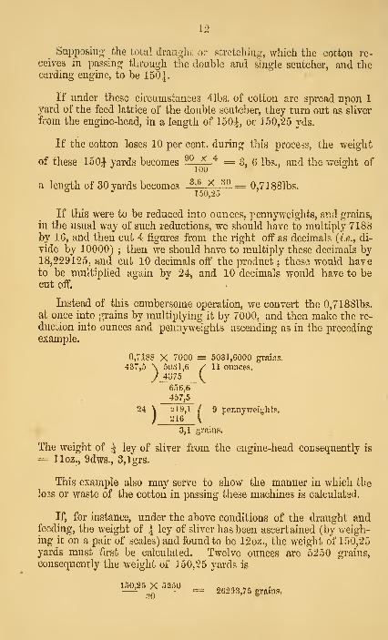
Supposing the total draiiglit oi* stretching:, which the cotton re-
ceives in passing through the double and single scutcher, and thecarding engine, to be 150|.
If under these circumstances 41bs. of cotton are spread upon 1
yard of the feed lattice of the double scutcher, they turn out as sliver
from the engine-head, in a length of 150|, or 150,25 yds.
If the cotton loses 10 per cent, during this process, the weight
of these 150i yards becomes ^^LA.'^ = 3, 6 lbs., and the weisrht of''
100 °
a length of 30 yards becomes H-A-^^ 0,71881bs.° ^150/2.5
If this were to be reduced into ounces, pennyweights, and grains,
in the usual way of such reductions, we should have to multiply 7188by 16, and then cut 4 figures from the right off as decimals (/.e., di-
vide by 10000) ; then we should have to multiply these decimals by18,229125, and cut 10 decimals off the product ; these would haveto be multiplied again by 24, and 10 decimals would have to becut off.
Instead of this cumbersome operation, we convert the 0,71881bs.at once into grains by multiplying it by 7000, and then make the re-
duction into ounces and pennyweights ascending as in the precedingexample.
0,7188 X 7000 = 5031,6000 grains.
437,5 \ 5031,6 / 11 ounces.
) 4375 V^
656,6
457,5
24 \ :ii9,l / 9 penny;__in6_\
weijihfcs.
3,1 grams.
The weight of \ ley of sliver from the engine-head corxsequently is
= lloz., 9dws., 3,lgrs.
This example also may serve to show the manner in which the
loss or waste of the cotton in passing these machines is calculated.
If, for instance, under the above conditions of the draught andfeeding, the weight of \ ley of sliver has been ascertained (by weigh-ing it on a pair of scales) and found to be 12oz., the weight of 150,25yards must first be calculated. Twelve ounces are 5250 grains,
consequently the weight of 150,25 yards is
150,25_Xi250 _ 2C293.75gr,i„,.

13
To reduce theso into pounds they must be divided by 7000
—
20293,75
7000= 3,75625lbs.
We have now the proportion
—
41bs. : 3,756251bs. = 100 : x
X = ^IM^ = 93,94
Tlie cotton therefore has lost 100 — 93,9 = G,l per cent.
The loss suifered by the cotton in passing through the opener canbe ascertained simply by weighing ; by passing, for instance, lOOlbs.
through the opener, and deducting the weight of the opened cottondelivered from these lOOlbs.
This loss added to the one calculated before chives the total loss
or waste.
The cotton is brought into the market in bales of 300 to 4001bs.,
firmly compressed by hydraulic pressure. The greatest part of the
seeds have been removed by the machines called gins, before packing.
In many kinds, however, a large quantity of them is still left, whichjointly with various other impurities amounts to 10 to 30 per cent,
of the gross w^eight of the cotton.
Before the thread can be formed, the cotton must be loosened andcleaned, then all the fibres must be placed parallel to each other, anda uniform section must be arrived at.
This is effected by a series of preparatory machines, which wewill describe one after the other.
MIXING.
The first process is the mixing, generally done in the following
way. The contents of one bale are spread out in a layer, the thick-
ness depending upon the number of bales to be mixed, upon this the
contents of a second bale are spread, and so on. Frequently the
cotton is damped a little during this operation, to make the fibres
better adapted for stretching. Generally different kinds are mixed;

14
ZtZt ^^%'''/'' ^^.^^^^^^^ l^ble a sample of the proportion of theseparate sorts for various number;-
"''rs of yarn.
No.

15
The cotton is spread upon this feed cloth and taken forwEU'd by
•I i fi!l vihhprl rnllpr B ffir/ 5, Fl U) to the fluted feed rollers 6,
'^'1f*- S'£e it^^seizfd aac/ carried forward by the teeth
of theftrst cylii^der D. Below the cylinder and concentnc with it
is "irid formed of sharp-edged iron bars e, between winch and the
eth/: til: cotton is opLd!ff f
-' ^^^Sf'rt"<^ ^f.^t *1^
bars. This process is repeated between A, fi ; A, S,^ A, -^3,
when the cotton is delivered upon rAie straight gr d ^.The
KHer is formed by iron bars, having alternately equal depth, Fu/.^,
Pl I andlsedbelow by a board turning on bmges, and pressed by
; eve against the bottom of the bars Between the top. ot the
Lrs a space is left of one-eighth of an inch in width.
G and G, Fill. 7, PI H, are two reTolving cylinder sieves, be-
tween which he cotton dissolved into flakes IS guided fx.^^nso aiTanged as to exhaust the air from the mside of both cylindei
sieves.
Emero-in- from these, the cotton is seized by the rollers
TI aiSSfealy carried to the delivery lattice K which is put u to
motbn dmUarVto the feed lattice A, by three pulleys keyed on the
revolving shaft K,
The whole space from C? to / is encased by^^fij^v ttffan is
so that the air required for replacing that exhausted by *« f^°;J
sieve-cyhuders and blown out by the fan.
The cylinder D has 12 rows of teeth, Fig. 6, PI II, while each of
the other cylinders has only four rows.
The machine is driven in the following manner:
On the shaft of the cylinder D, a pulley of Win. diameter is keyed
on, making 1000 revolutions per minute.
If the main shaft makes 132 revolutions, (as we will suppose it
to do fol^aU the various machines,) the drivmg pulley must have a
diameter of 155^>|l^=75iin.
If a pulley of such a largo size is objectionable, a counter shaft
may be used, and the velocity ratio = i^^ = 7,5757 divided into
two factors, for instance 3 and 2,525. If we now place a 30m. pulley

16
on the main shaft, and a lOin. one on the countershaft, the other
Cter'of'^^^^^^«^^^' ^^i^i^g- the opener, must have a
1000 X 10 X 10 _ ^ ^132 X "30 ~ 22,73—or nearly 22f inches.
The countershaft may also be avoided, by running the main shaftlor all the preparatory machines at a greater speed. We will however, retam our first supposition, namely, that the drivino- pulley onthe mam shaft is 75f inches in diameter. It must be "sufficientlybroad to carry two straps at the same time. One of them drives, asalready stated, the cylinder A, and simultaneouslyA ; the pulley onthe latter having 8in. diameter. The second strap drives i> with a12in., and i>2 with a 9m. pulley.
As the number of revolutions stands in inverse ratio to thediameters of the pulleys
—
?z fori) is^Q"Q X iQ == 833^ •
71 „ A ^ '^><il= 1111,11
n „ D, ^ l^pjl == 1250o
Another 7Jin. pulley, on the shaft of the cylinder A, drives a Gin.
pulley on the fan shaft, the latter accordingly making i^^Hi' =1510,41 revolutions.
^
The other moving parts of the opener receive their motion from anintermediate shaft placed in the front partof the machine, driven directfrom the mam shaft, and making 16| revolutions. If the pulley onthis shaft has a diameter of 24in., the driving pulley on the mainshaft must have one of^^ = nearly Sin. This is generally
the diameter of the main shaft itself, and the strap is placed directlyon It, without a pulley being required. If the shaft is more or lessthan om., the pulley on the machine shaft must be made proportion-ately more or less than 24in.
_
On this intermediate shaft there is, firstly, a pinion of 24 teeth,driving the shaft K, by a wheel of 36 teeth. As the pulleys keyedon K have 3^ inches diameter, their circumference is 3,14 x 3,25= 10,215, and their circumferential velocity 10,215 x 11,11 =ll3in., this being also the speed at which the delivery lattice Z"travels.
"^
The same pinion of 24 teeth also drives the lower sieve-cylinder
by a wheel of 81 teeth, which consequently makes ^^>^^ X ^^ ^4,93 revolutions.

17
The upper sieve cylinder is provided with a wheel of 120 teeth,
gearia^i^ with that of 81 teeth on the lower cylinder shaft, and ma-
king iMi^^lii = 34- revolutions per minute.
The roller / is driven in the same way as K, taking the upper
roller I^ round by two spur wheels of equal diameter. Both rollers
have the same diameter as the pulleys on K^, consequently also the
same circumferential velocity of 1 1 3 inches.
The intermediate shaft further carries a bevel wheel of 24 teeth,
gearing into another of 40 teeth on a side shaft ; on the other end
of the'latter another bevel wheel of 24 teeth is fixed, working into a
fourth of 40 teeth, on a shaft below the feed roller C, This shaft
therefore makes iM_^-.>Lii^iii = 6 revolutions.40 X 40
It drives firstly J.., at the rate of one revolution of A^ to 1^ of
the shaft, J.2 making consequently four revolutions. The pulleys
keyed on A., have oin. diameter ; the feed lattice A accordingly
travels 4 X 3,14 X 3 ~ 37,68 inches per minute.
This shaft drives secondly the lower feed roller by equal sized
wheels, the roller making also six revolutions. As its diameter is
2,5 inches, its circumferential velocity is 2,5 X 3,14 X 6 = 47,lin.
The top roller is taken round by contact with the bottom one, so as
to have the same circumferential velocity.
The roller B is put in motion from Ao, the pinion on Ag having 38
and the wheel on B 31 teeth. The roller therefore makes A-J^—?^
31
=: 4, 6 revolutions; its diameter being 3Jin., the circumferential
velocity is 3,14 x 3,25 X 4, 6 = 47in.
Both feed rollers are fluted, and the top one pressed against the
bottom one by levers and weights.
Instead of this opener, which is chiefly used for short staple cot-
ton, various similar machuies are applied, most of which however are
constructed on the same principle. Fine cotton of a long staple is
generally cleaned by a willow, because it contains less impurities,
and would be damaged by the opener. For inferior kinds, however,
the willow is entirely out of use ; we therefore omit describing it.
DOUBLE SCUTCHER.
This machine cleans the cotton of the greatest part of the re-
maining impurities, and foiTQs it into a lap.
We describe in the following pages a double scutcher as made byParr, Curtis, & Madely, and furnished with Lord's feed regulator.

18
k^Fuj, 2, Plata III.—is an endless feed cloth; B a fluted roller
turning loose on its axis; and G- the feed rollers. The cotton is
spread on the feed cloth, and conveyed to the feed rollers by it andthe roller B, the latter being taken round by contact with thepotton.
D is a beater, with two blades, d d, standing opposite each other,
at 17|in. distance, which, quickly revolving, strike the cotton whenit emerues from the feed rollers. Below the beater is a grid concen-tric with the way described by the blades, and formed of sharp-edgediron bars, d^, with spaces of about -^in. between them. By the beater,
assisted by these bars, the cotton is dissolved into flakes, while theseed kernels and other coarse admixtures fall through the grid.
F is a fan exhausting the air from the inside of the two sieve cyliu-
ders, E and Ei; the space between the feed rollers and the back partof these cylinders is enclosed by sheet iron on all sides, so that theair required for replacing the exhausted quantity can ouly enter be-tween the bars of the grid. The current of air thus created preventsthe cotton flakes from falling through the grid, but carries themup to the sieve cylinders, between which the cotton passes as betweena pair of rollers, while the dust contained in it is carried off" by thefan. Between the beater and the sieves there is a grid of bars ofalternating depth, closed below by a moveable board. The bars ofthis grid are placed about I'm. apart, so as to allow dry leaves andparticles of the capsules to fall through.
The fleece is stripped off the sieve cylinders by the rollers G and
Gi, and again consolidated and moved forward on a horizontal plate
until it is seized by the second pair of feed rollers, Co Co. It then
passes through a third pair of feed rollers, O4 C^, when it is again dis-
solved into flakes by the second beater, in the same manner as be-
fore. By this beater Di, the fan F^, the sieve cylinders Eo E.j, and the
rollers G2 G-3, the foregoing process is repeated. The fleece then passes
between the upper and the tvv'O lower calender rollers, H, Hi, H2, unto
the first lap roller, I, being compressed by the solid roller, h,
which is taken round by contact v/ith the fleece. By the two lap
rollers, I and I^, the cotton fleece, now called lap, is coiled upon the
loose roller, K. During the coiling the roller K receives a continual
pressure by means of the rack M and the break L.
The machine is put into operation by driving both beater shaft?
simultaneously from a common pulley on the main shaft. Eachbeater carries an Sin. pulley, and must make 1,600 revolutions. Asthe main shaft makes 132 revolutions, the driving pulley must have
- 1600 X 8r. ^
a diameter of —^3-^— =97 inches.
If a pulley of that size is inapplicable, the velocity-ratio -^ =12,1212 must be divided into two factors, say 3,5 and 3,463, and a

19
shaft counter mufet be used. If we place on the latter a pulley of
8 X 3,46 = 27,7 inches for drivmg the beater, and another pulley
of 10 inches, the diameter of the main driving pulley will be found
= 10 X 3, 5 = 35in.
132 X 35 X 27.
n = 8 X 10= 1600.
Each beater shaft carries another pulley of 5 in. diameter, driving
a pulley on each fan shaft of 6|in. The number of revolutions fur
both fans consequently is
_ ipon X 51185,
A third pulley of 4jin. diameter on the shaft of the second beater
acts upon a 2 7Jin. pulley on an intermediate shaft, from which all
the other revolving parts of the machine receive their motion. Forthis shaft
n ^ M^^x-iila =. 58027,5
It carries, firstly, a pinion with 16 teeth, gearing with a wheel of
63. Connected to the latter is a second pinion of 16 teeth, driving a
v/heelof78; fixed to this is a third pinion of 17 teeth, workingsimultaneously into two wheels of 32 teeth each, one upon each
lap roller. These consequently make ^so x i6 x le X^t^ ^ ...bo X ' y X "2
revolutions, having diameters of 9in. each. Their circumferential
velocity is = 9 X 3,14 X 7,75 = 219 inches.
The intermediate shaft drives secondly the upper callender roller.
As already stated, it carries a 16 teeth pinion, gearing with a wheelof 13 teeth; connected with this is another pinion of 14 teeth (the
stop pinion), driving the top callender roller Uy a wheel of 96teeth. The number of revolutions for the latter is therefore
280 X 16 X 14 __ j^^37Q7^ ^1-^ile ij-g diameter is = 6 inches, and its
circumferential velocity = 6 X 3,14 x 10,37 = 195,38. This cal-
lender roller carries a wheel of 24 teeth, working with two others of20 teeth each, on the lower callender rollers. These consequently
10,37 X 24make —'—^—^ =12, 445 revolutions; as they are 5 inches in
diameter, their circumferential velocity is also
5 X 3,14 X 12,445 = 195,38.
The intermediate shaft further turns the driving cone of the feed
regulator. A wheel of 63 teeth on the former acts upon one of 35teeth on a second shaft, that carries a wheel of 33 teeth driving

20
another one with 28 on a side shaft. A wheel of 50 teeth h fixed on thelatter, gearing with another of 32 teeth on the shaft of the drivino-cone, which accordingly makes ^
280 X 63_X_33_X 50
35 X 28 X 32 = 928,12 revolutions.
Tlie top callender roller drives by a wheel of 60 teeth, anotherot 30 on a side shaft; the latter carries a wheel of 38 teeth, workingwith another of 28 teeth on the bottom feed roller, C, of the thirdpair. For it,
_ 10,37 X GO X 33^^' — 30 X 28 = 24,44
The top roller, C„ is taken round by the bottom one by twowheels of 8 teeth each. The diameter of these rollers bein^ 2 inchesthen- circumferential velocity is 2 x 3,14 X 24,44 = 153,48.
'
The roller, C„ carries a pinion with 1? teeth, drivino- the top feedroller, Q,, of the second pair by a wheel ui 19 teeth. The latter there-n , 24.U X 12lore maaca ^cj = ^5,43 revolutions, taking its bottom roller
Co, round by two wheels of 10 teeth each. Both have 2|in. diameter,their circumferential velocity consequently is = 3,14 X 2^ X 15,43^—^ 1 10,0 7,
Between the second and third pair of feed rollers therefore a
stretching or draught of -^~ = U takes place.
The wheel with 10 teetli on the roller G^, drives by means of acarrier wheel (f = 50), a wheel of 14 teeth on the roller G„ whichmakes ^_M^^]<J!^ = 11,02 revolutions.
This 14 teeth wheel takes the roller G round by another wheelor the same size.
Jn fixed connection with the carrier wheel of 51 teeth is another01 /o teeth, driving one of 170 teeth on tho shaft of the sieve-
cylinder F, The latter makes l^ii^i^x^s _ ^^^ revolutions.o I X 170
This wheel (/ = 170) drives by another of 124 teeth the upperupper sieved, making ^li^JZlL^ 1,78 revolutions.
^
The wheel of QO teeth on the callender roller E, mentioned before,drives by a carrier wheel (/ = 30), a wheel (t = 14) on the roller G^,
?^ of the latter = IM45_^>^. ^ ^^^^^^ ^^ ^^^^^^^^ wheel of 14
teeth, the roller G^ receives the same number of revolutions.

21
The diameter ol' 6'. and (J^ — '^^ inches, and their ciL'cumferential
velocity is 3,14 X HX 17,78 = 181,6 inches.
Between G., G^ and the callenders, consequently a draught of
'^^M3 and between Go G. and the Ipd rollers, one of -^^^ =181,6
" J«i>^
1,206 takes place.
Connected to the above carrier wheal, .(^= 30) is a wheel {t = 44,)
driving one of 170 teeth on the sieve cylinder E3, which, therefore
makes l^iiil><lOj<il =* 2,147 revolutions.30Xi7U
The wheel {t = 170) drives by another of 124 teeth the cylinder
E,; n for this = 2^^ = 2,9i3.
THE FEED REaULATOR.
PI lY., Fig. 1 to 7.
In the machines without regulators the feed lattice travels with a
constant speed of about ]. of the circumferential velocity of the lap
rollers; therefore a length of one yard spread on the feed lattice is
delivered as three yards of lap.
In order to obtain the lap as uniform as possible, the feed lattice
is marked from yard to yard, and upon each yard an equal weight of
cotton is placed. A pair of scales is put beside the machine, uponwhich the attendant has to weigh, every time the quantity for each
yard. This takes much time, is troublesome, and frequently
incorrect, in consequence of the speed at which the feed lattice
travels. Besides this, the straps that carry the staves forming the
lattice, stretch, consequently the length of the lattice varies.
These drawbacks are entirely removed by Lord's feed regulator.
It is based upon the following principles : the feed lattice is madeto travel at a variable speed, namely, in tlie inverse proportion to the
thickness of the layer of cotton between the feed rollers ; so that if
this thickness increases, the velocity of the feed lattice grows less, andvice versa.
Before showing how this idea has been carried out. We will
consider the mode of transmitting the motion from the driving cone
T. By a strap, the rotatory motion is first communicated to the driven
cone ^, which carries on its shaft a worm a, gearing wath the worm-vvheel i) of 88 teeth, and thus driving the shaft A^. On the laiter
three pulleys of 3|in. diameter are fixed, on which the tied lattice
straps run. A pinion of ] 5 teeth on the same shaft, drives by a wheel

22
of 8 teeth, the feed roller C. The latter drives by an equal wheel of8 teeth, the top feed roller C. The number of revolutions of the feedrollers is therefore always V times that of a shaft A,.
The two bodies commonly called cones, are, properly speakino',surfaces formed by the rotation of a hyperbola round its axis ; thedrivmg cone is concave, the other convex. As we have seen in theintroduction, this mechanism serves to produce a uniformly variablemotion, so that with a uniform rotation of the driving cone, the vari-ation in the number of revohitions of the driven cone, produced byshifting the strap, is proportional to the length for which the straphas been shitted.
We here repeat that the two axles must be parallel, that tlie strapmust run always at right angles to these axles, and that the sum ofthe diameters of the two circles, traced by the centre of the strap onthe cones, must remain the same for every position of the strap.
The diameter of the larger end of each cone is GJin., that of thesmaller one 3^—the sum accordingly 9| = 9,625in. The length ofthe side of the cones is 11 in The cones stand of course reverselyopposite one another, and are so placed that the top of the drivingand the base of the driven cone are below.
^
In the lowest position of the strap, n of Aois>
928.12 X 3^ ^ 928,12 X 3,125 ^8S X tii 88 X 6,5
~ ^'^^
in the highest
« _ 928,12 X 3,125n = ~— = 21 q-J,
88 X 3,125'^^'-'^
iAo^t*^'®. P^?^^^^^ ^^'' '^^ feed- lattice are 3iin. in diameter, or10,225in. in circumference, the speed of the feed-lattice varies from10,22o X 5,07 to 10,225 X 21,93, or from 51,83 to 224,2.
The circumferential velocity of the lap rollers is as shewnabove, 219in. The lowest position of the strap therefore corresponds
to a draught of i^ = 4,22, while for the highest position of the
strap the draught is ^^ or approximately 1
The regulator is usually so adjusted, that the draught is = 3; i.e,
with a standard weight of cotton spread on the lattice and while thestrap is in its normal position, tliree yards of lap are formed from oneyard of cotton given upon the feed cloth. ^Ye will now determinewhich position of the strap is the normal one for this draught.

23
The speed of the feed lattice must according to this draught
be ^ = 73, therefore the shaft Ag must make —^ = 7,14 revo-
lutions. If we call the diameter of a circle traced on the driving
cone d and the corresponding one on the driven cone ^, there must
be 928a2_x d _ 7 .^ ^,^^ ^^.j^i^l^
X
d ^^ 7,14 X 88
T 928,12
or, d == 0,677^^
0,677
For every position of the strap we also have f/ + ^ = 9,625 ;
^=9,625—^
Bj putting those two values of d to equal each other we get
9,625 — S = 0,6775
or, 9,625 = 0,677 8 -\-
S
9,625 = 5(1+0,677)9,625 = 1,6775
9 625and finally 5 = t^-~^„ = 5,74
d — 9,625 — 5,74: = 3,885.
This diameter must be sought on the driving cone and the
circle marked. The normal thickness of the layer of cotton to be fed
unto the lattice must now be determined.
If we suppose that one yard of the lap is desired to weigh lib.,
and that the cotton loses 5 per cent, in passing through the machine,
then for three yards, 3,151bs. will have to be spread on the feed cloth.
This quantity is exactly weighed and spread as carefully and uni-
formly as possible on one yard of the feeri lattice, and then the
machine is started. The top feed roller will be lifted up by the
thickness of the layer of cotton, and the distance thus produced
between the circumferences of the top and bottom feed roller is the
desired normal thickness.
After the feed rollers have thus been placed at their normal dis-
tance, the strap is brought upon the place, marked as before on the
driving cone.
The hook 0^ at the upper end of the drawbar 0, Fig. 2, pi IV.,
presses upon the bearings of the top feed roller, so that this drawbarparticipates in the vertical movement of the roller. The bar ends at
its lower end in a forked hook Oo supporting the lever p on bothsides, by the projecting edges jj^. The short arm p., of this lever rests
against the fixed bracket ^^s, while the longer one (about twenty times

24
the length of tlie other) tenniiiaie,-. in an eycj),. Tiie other end ofthe feed roller is connected in tlie same way with ji suniiar drawbarand lever, terminating in a similar eye ^5 Fi^. 3 ; Pi and ;?- are firmly
connected by the cross bar j;^. Anotbcjr rod c^, is joined with a pinto the centre c of this bar, and has a right hand thread cut upon theother end. Opposite to this is the rod c.; having at its lower enda left-hand thread. A long nut e couples both screwed ends, byturning which the distance between c- and c can be altered. The endC5 forms a moveable joint with the end of the lever /, that has its
fulcrum in/i and ends on the other side in a fork/o, which clips the
strap guide for the driving cone. For the purpose of guiding thestrap parallel, this strap gaidc/3 is connected to that of the driven
cone, /., by the link f^f^, the former swivelling upon f^, the latter
upon/g.
By turning the nut e therefore, the strap can be moved up or
down, and is placed in the before described manner, upon the markedplace on the driving cone.
The nut e is kept in its position by the lock-fork c^, Fig. 6.
If the required alteration in the length of c c-^ is more tlian thelength of the threads permits, the bracket p.^ must be differently
adjusted by the screws ^^^^ and n,.
The strap will now remain in this position so long as the thicknessof the cotton fed on the machine remains the same; if the latter
increases, the top feed roller will rise, and with it the points j^^^;^ andC5, while/2/3 and/ are lowered. The strap will by this means beshifted towards the top of the driving cone, and trace a circle of less
diameter on it, while the diameter of the circle traced on the driven conegrows larger; the shaft Ao and with it the feed lattice will consequentlymove slower. If, on the other hand, the thickness falls below its
normal value, the shaft A2 will turn faster. If the curves of bothcones are properly made, the speed of the feed lattice is in inverse
ratio to the thickness of the layer of cotton between the feed rollers, orthe product of the thickness of cotton multiplied by the number ofrevolutions of the shaft A2 is constant.
If the normal thickness is measured to be 0,5in. while n of Ao was7,14, and the speed of the feed cloth was 73 inches, then when the
thickness rises to 0,6in,, we have the proportion,
73 : 0,G : : ? : 0,5
? = "-"^ X 0,5 ^ gj0,6
or the feed lattice travels at the rate of 6 1 inches per minute.
The number of revolutions n^ of Ag is found similarly
n^ X 0,G = 0,5 X 7,14

25
If the cotton has been spread unevenly, so that its thickness onone side is 0,8, and on the other only 0,4, the regulator acts in the
same way as if the thickness was evenly distributed = ^'^'f
^''^ = 0,G,
because the motion of the strap is regulated from the centre of
the cross bar 23q.
It is evident from the preceding, that each yard of lap will weighthe same, whatever weight is placed on one yard of the feed lattice.
The weighing of the cotton therefore becomes unnecessary, and oneworkman can easily attend to two machines.
An alteration in the weight of the lap can be effected in two ways,
either by altering the normal thickness for the same draught, or byaltering the draught.
As regards the first manner, it is evident, that if instead of
spreading 3,l51bs. on one yard of the feed lattice for determiningthe normal thickness, now for instance 51bs. are put on, (the draughtremaining equal three as before, and the cotton losing 5 per cent. ) one
yard of lap will weigh ^^ — l,58lbs. Therefore the weight of the
cotton required for three yards of lap must first be calculated, thenaccurately weighed and spread on one yard of the feed lattice as
uniformly as possible. The normal thickness being thus accurately
produced, the strap is simply guided to the place on the driving cone,
which corresponds to a draught = 3.
Regarding the second manuer, an alteration in the weight of a
yard of lap also naturally takes place as soon as a greater or less
length of lap is made from the same quantity fed upon the lattice.
If, for instance, only two yards of lap are made from the formerweight of 3,15 lbs., (the draught being reduced fi-om 3 to 2), oneyard of lap will weigh 1| lbs., instead of 1 lb. as before. In this
case the speed of the feed cloth for the normal thickness of the layer
of cotton must be one-half of the circumferential velocity of the lap
rollers, or ^- = logi
By an analogous calculation to the one made above, the diameterof the circle is determined, which the strap must trace on the drivingcone in order to impart this speed to the feed lattice. The normalthickness must then be placed ]3etween the rollers and the strap puton the calculated circle in the same manner as described before.
To avoid this calculation the strap guide for the driving conecarries a pointer, which indicates on a graduated scale the normalpositions of the strap for any draught v/ithin the limits allowed bythe length of the cones j these limits being as shewn before, 4, 22,and 1.

26
If the cotton is spread on so thick that the speed of the feed
cloth would ftiU below the lowest limit of 51,83in., the strap drops
off the cone.
A few remarks on some of the workmg parts remain to be added.
The first pair of feed rollers have 2 inches in diameter, or 6,28inches in circumference. We showed before that their number of
15revolutions is -g- of that of the shaft Ao. If for a draught of 3 the
15latter makes 7,14 revolutions, the feed rollers will make -j x 7,14
= 13,4, and their circumferential velocity will be 6,28 X 13,4 =84,15.
The feed lattice, however, only travels 73 inches, consequentlythese rollers gain on it 11,15 inches per minute.
The upper callender roller is pressed heavily against the two lowerones. The rod c/—F'i{/. 1, Plate IV.—is suspended in gl from thebearing of the upper roller, and carries the lever cjo, resting with its
short arm against the bracket g., while the end of the longer armcarries the Hnk g^. This again supports the lever g.^, the short armresting against the bracket g^, and the longer one carrying a weight
^7. The pressure exercised on the roller amounts to 50 cwt
The two lap rollers I and Ii, turn in the same direction. Theroller K lies loosely upon them, and receives its motion by contact.
The end of the roller K is kept down by the head Mi of the rack M,provided with two small friction rollers, i^ and i^. The pinion % gearswith the rack, and is keyed on the same shaft with the break L. Theother end of the roller K is kept down in the same manner by a si-
milar rack and pinion. The break band is connected with the lever Jig,
turning on L2, in such a manner as to be tightened by the weight L,supported on the lever. The other arm of the latter finishes in a step
board L4, by treading on which the workman can suspend the break-ing action.
STOP MOTION OF THE MACHINE.
If the stopping takes place by guidiug the strap upon the loosepulley on the intermediate shaft at the head of the machine, thebeaters as well as the fans remain in motion. Besides this the ma-chine has a self-acting stop motion which operates as soon as the coil
of lap obtains a sufficient size. The rack M carries a nose Jc^, adjust-able in a vertical direction by a screw. As soon as the rack is lifted

27
to a certain point by the thickness of the coil, the nose h^ strikes
against the leyer h^. The latter has its fulcrum in k^, and its otherarm Ic^ rests against the pin Ic-^. This pin forms at the same timethe fulcrum for the lever h^, so that if the nose k^ lifts the lever kz
up, these two levers act like one swivelling on k-. The lever k^^
terminates in a slide piece kj, resting upon a corresponding slide
bracket kl Upon k^ being turned, k-, slides off ^3; this causes
the lever Z^g, hinged on /j^o, to drop, and throws the pinion ^^ outof gear with the wheel k^...
The axle of ^n is clipped by a forked bell crank lever k^-, having
its fulcrum in 7^13; a downward motion of the axle of Z'n causes the
other end, k^^, to move in the direction of the arrow. A rod I
which can be adjusted in length by the screw /;
—
Fig. 7—connects
Z^ji with the lower end l^ of the lever h, swivelling on /3, This
lever is connected in l^ with the lever l^^ which has its fulcrum in
4. The latter embraces with its other arm, /-, the shaft of the
driven cone, so that a movement of the point k^^ in the indicated
direction causes the worm and worm wheel a and 1) to become dis-
engaged.
If the machine is stopped in this woy, the rollers and the
driving cone will remain in motion, besides the beaters and fans.
The continuation of the motion of the lap rollers, while the callenders
are stopped, causes the lap to break.
SINGLE SCUTCHER.
The lap thus produced is then made more even on a single
scutcher. This machine is with a few deviations the same as the
second half of the double scutcher. The feed rollers are driven by a
side shaft from the upper callender roller at a threefold velocity-ratio.
Three laps from the preceding machine are fed simultaneously into
this one, so that one yard of fleece taken in by the feed rollers con-
sists of three yards of lap from the double scutcher placed one uponthe other. Out of these a new lap of three times the length is
formed. The weight of one yard of lap delivered by the single
scutcher is consequently equal to the weight of one yard of lap fromthe double scutcher, less the loss of weight occasioned by the removalof impurities.
The three coils to be fed on the machine are each placed on a
bar and put on the feed lattice, one behind the other, so that duringthe uncoiling the feed rollers are supplied uniformly from all three
coils. In the sides of the frame slots are made for these bars, andthe three coils are forced by the progressive motion of the feed lattice
to turn round the bars.

28
The width of the machine, i e. the width of the lap to be fonned,
depends upon the width of the carding engine; both must be the
same.
All the other parts, beaters, fans, sieve-cylinders, &c., are exactly
the same as in the double scutcher; we therefore think it superfluous
to dwell any longer upon this machine.
CARDING ENGINE.
The different objects desired to be attained by carding, are the
following:
—
1. To place all the cotton fibres, hitherto irregularly crossed in all
directions, into parallel positions.
2. To remove completely any impurities that might have remained
3. To remove all fibres which through being too short, would
interfere with the strength of the yarn.
4. To form the lap fleece into the sliver or riband necessary for
commencing the spinning process.
The first of these objects is attained by a considerable stretching,
ie. extension in a longtitudinal direction. Each unit of the lap is
extended to many (say 100,) times its own length, and appears then
as a riband of 100 times the length of the original fleece. The pro-
portion of the length of a unit of the lap to the length of the sliver
formed from it, is called the draught, being equal to 100 in this case.
The impurities, as dry leaves etc.- become fixed between the wire
staples of the revolving drums described below, and are removed fromtime to time by stripping.
The dust as well as the short fibres are forced out by the great
circumferential velocity of the cylinder, and fall to the ground.
The formation of the sliver or riband finally is efi'ected by the
funnel or trumpet.
There are many kinds of carding engines in use, differing how-
ever little from each other. We select for description a double
carding engine, as made by Piatt Brothers and Co., 48 inches wide
on the wires.
a, Fig. 1, PI. Y., is a roller, which by revolving uncoils the lap
fleece i)ut on a bar, so as to be in contact with it; 1) l^ are two feed
rollers; c the taker in; d the dirt roller; f7, to cJiq the rollers; e to

29
e^ the clearers; D the back cylinder; and D^ the front cylinder; E theslow tummer; E^ the doffer; / the comb; g a web guide; g^ thetrumpet; li and Ih the back rollers; and % and i^ the front rollers ofthe drawbox; /*; the coilercallenders; m the revolving coiler; /the caninto which the slivers are deposited; n the revolving dish by whichthe can is tnrned round.
MOTION OF THE VAEIOUS PARTS OF THE ENGINE.
There is a fast and a loose pulley of 16 inches diameter, on theshaft of the front cylinder, which must make 150 revolutions perminute. As the main shaft makes 132 revolutions, the driving puUeymust have a diameter
,150 X 16
d = Y^ = 18.18m.
From the front cylinder shaft the back cylinder is driven by two20in. pulleys, consequently it makes also 150 revolutions. There is
another pulley of 20in. diameter on the front cylinder shaft, whichdrives the clearers e^, e^, e^, ^g, by means of four 7Jin. pulleys, makingthe number of revolutions for each of them
20 X 150n = -77^— = 400
The clearer ^4 has a pulley of 9in. diameter, and makes conse-
quently"-—
g
= 333,33 revolutions.
In the same manner the clearers e, e^^, e.^. e^, are driven from theback cylinder shaft at 400 revolutions per minute.
A 12in. pulley on the back cylinder shaft drives a Gin. pulley on150 X 12
the taker"in shaft, n of the latter therefore is = ^ = 300.
Another pulley of lOin. diameter on the front cylinder shaft
drives an 18in. pulley; attached to the latter is a pinion of 36 teeth
working into a wheel of 180 teeth on the doffer shaft, for the latter
150 X 10 X 36n = ~T8 X 180 = ^^'^^*^
In the same maiiner the slow-turamer receives 16,66G revolutions
from the back cylinder shaft.
A Tin, pulley on the doffer shaft drives the rollers d- io dy^ by
means of pulleys of ojm. diameter, n 01 these = ^—5 = 21,21.
Tlie rollers d^^ d., d, d^ d-^ are driven in the same way from the
slow tammer shaft, as well as the dirt roller d, but the latter revolves
in the contrary direction.

30
A bevil wheel of 30 teeth on the doffer shaft gears with anotherof 40 teeth on a side shaft, on which there is a pinion of 14 teeth(the change wheel) gearmg into a wheel of 120 teeth on the bottomfeed roller. For the latter,
16,666 X 30 X 14, ^„
^ = 40 X 120 = ^>^^^-
The top feed roller is put into motion from the lower one by twowheels of 17 teeth each. The wheel with 17 teeth on the bottomfeed roller drives by means of a carrier wheel, another of 48 teeth
1 458 ^ 17upon the uncoiling roller ; the latter makes therefore ' '
^g— =
0,516 revolutions. It must have the same circumferential velocity
as the feed rollers, because otherwise the lap would be torn. •
The wheel of 180 teeth on the doffer shaft mentioned above drivesthrough a carrier wheel another of 26 teeth on an intermediate shaft,
from which the drawbox rollers, callenders, coiler, and can dish
receive their motions. For this shaft 7i = —^—— := 115,38
On this shaft there is, firstly, a wheel of 40 teeth working into
another of 30 teeth on the bottom back roller h of the drawbox
H5,38 X 40 _n = 30— - 153,84
There is another wheel of 35 teeth on the intermediate shaft,working into one of 24 teeth on the bottom front roller z of thedrawbox,
115,38 X 35n = 24 ' ==" 168,262
The two top rollers Ji, and /, (Fig. 1, PI. YI.) are pressed downby the weighty; and carried round through contact with the bottomrollers.
ma*
On the intermediate shaft there is further a wheel (t = 25) gear-s..^ with another of 20 teeth, to which a mitre wheel of 20 teeth is
connected, driving by the ether mitre wheel the upright shaft {Fi(/, 1,P/. VI.) from which the callenders and the top and bottom can-
motion are worked; for this upright }i = --"7;^--"-|^-— = 144,23
One of the coiler callenders is driven from it by a pair of mitresof IG teeth each, and cousequently makes also 144,23 revolutions.The second callender is worked from the first by two equal wheels of24 teeth each.

31
There is further a pinion of 36 teeth on the upright, driving the144 23 ^ 36
coiler, which has 106 teeth, and makes consequently —'jq^ == 48,98 revolutions.
Lastly, there is a pinion of 8 teeth upon the upright, working
into a wheel of 48 teeth; fixed to this is another pinion of 15 teeth,
which drives by an intermediate wheel the can-dish. The latter has
120 teethj and makes
144,23 X 8 X 15^^
^3 ^ j^>3^— = 3 revolutions,
48 98Consequently for each revolution of the can, —- = 16J layers of
sliver are deposited in it.
The comb / {Fig. 1, Fl V.) is worked in the following manner:
• A 24in. pulley is fixed upon the front cylinder shaft, and drives
another of 4in. diameter on the shaft A. A 5^in. pulley on the
latter drives a 3 J in. one on the eccentric-shaft B, which therefore
. 150 X 24 X 5,5, ,, . o 1 4--
makes^ ^ ^^ ^^ 1414,3 revolutions.
The throw of the eccentric is jin. ; it is clipped by the rod c
acting upon the lever d, to the other end of which, d^, the comb/ is
fastened.
The short arm r/j = 2|^in. long; the longer arm Jj^Sjin.;the fulcrum is in d^. The comb therefore makes for each revolution
of the shaft B an up and down stroke of
^gi
"" = 1,05 inches.
All the rollers marked b c d e J) and E {Fie/. 1, FI. V.) are
covered with cards. These consist of a strong cotton cloth, thickly
covered with fine wire staples, that are ground sharp, and have a
length of 0,4in. The staples or teeth form an angle of 20 to 30
degrees with the radial direction. Those of the rollers marked b^
d I) and D^ turn in the same direction as the unlapping roller a ; all
the others in the contrary way. The wire staples of the cards incline
in the same direction as the rollers revolve on those marked b c d J)
Di and e to e^, so as to advance them; on the others they incline in
the opposite sense to the direction in which the rollers turn. The space
between the feed rollers and the doffer is closed in by covers on all
sides so as to prevent the cotton from flying off. The covering on
the top consists of 4 lids that can be opened on both sides of the
cylinders, and kept in this position by the hooks o and the pins o^
{Fig. 3, Fl. yi.)

32
A bottom of sheet iron extends below the whole of the rollers,
except below the two cylinders, where it consists of a grid of trian-
gular wooden bars, so as to allow the dust and separated short fibres
to fall through. This bottom enclosure fits on its entire length
closely to the rollers above.
The rollers c d to d^ and e to e^ are placed so close to the backcylinder as just to miss touching it; the same takes place betweenthe rollers d^ to d^^, e^ to e^,, and the front cylinder D^; e^ being simul-
taneously in the same position to the slow-tummer E.
The same distance must be kept between each roller and the
clearer belongmg to it ; for instance, between e and d^, e^ and 4, &c.,
while ^3 has to work close to J^ and d^ at the same time, and e^ to d^
and d^.
In order to allow the rollers to be brought so close to one another,
the bearings of all the clearers are adjustable in a radial direction,
and those of the rollers d in this and a tangential direction as well.
(Fl YI, Ff^. 4.)
To enable us to follow the carding process, we will put the
circumferential velocities of all the various drums and rollers
together : n is the number of revolutions given above ; d the
diameter ; u the circumference = d x 3,14, and v = n X ?/, the
circumferential velocity.
a

33
again to 18849 iiiclies. The wires of the dirt roller meeting those
of the cylinder, with their points inclined against them, the impu-rities (parts of the covering of the seeds, &g.) are fixed amongstthem, and thus separated from the cotton. The same is done byboth drums, in consequence of the inclination of their staples.
The cotton then passes under the clearer e without adhering to
it, as can be seen from Fig, 8, PL IV., but is taken from the
cylinder by the roller d^ and from this by the clearer e, from which it
returns again to the cylmder D. It then passes over (L and e^ andback upon the cylinder. The same operation is repeated several
times, till the cotton is at last removed from the doffer E^^ by the
comb. By these frequent changes in the longitudinal extent of the
fleece, measuring originally 9,14 inches, the fibres are combed or
brought into parallel positions.
The cotton when combed off the doffer appears as a thin fleece
and is led over the guide g, and through the trumpet g^, Fig. 1, PLVI, into the draw-box. Between the front and the back rollers of
the latter it is stretched or drawn. For the rollers hlh is
n ^ d u V153,84 l|in. 5,497 845,45
for / i^—168,262 2 6,28 1056,67
The draught accordingly is345 45
— IJ-
To keep the sliver tight between the front draw-box rollers andthe coiler callenders, the latter must gain a little over the former
;
'/. e., their circumferential velocity must be somewhat larger, say 1
2
inches per minute. The number of revolutions for the callenders
we found to be 144,23 ; if v for them is to be 1056,67 + 12 =1068,67, their diameter must be
1068,67 _ 2,36 inches.144,23 X 3,1415
The riband now passes through the coiler m, Fig. 1, PL VI, intothe can. The coiling disc carries a short oblique tube passingthrough it, the upper opening of which lies in the centre of revo-lution of the disc, while the lower one is at a distance equal to { ofthe diameter of the can, measured horizontally, so that in revolvingit describes a circle between the circumference and the centre of thecan. If the can has a diameter of 9 inches, the horizontal distancebetween the upper and lower opening will accordingly be f
=2,25 inches.

34
Let A, Fig. 2, PI. VI, be the centre of the can (| size) ; A C its
radius, = 4,5 inches ; B the centre of the coiler, and the dotted
circle the way described bj the centre of the lower opening in the
coiler in revolving round B. If the centre stands at first in A, it gets
in half a revolution to C, where it would touch the inside of the can,
if the latter was standing still. But during half a revolution of the
coiler, the can turns Yy^ioY ^^^ ^^^'^^ circumference is 3,14 x 9 =
28,26 inches, the point C moves ^^^=0,867in., and gets to Q^. If
we draw a diameter through B at right angles with A C, cutting the
dotted coiler circle in D, and draw a line through A and D, it will
intersect the circumference of the can in a point E. We then cut a
piece E Ej off on E 0, equgl ^^j draw A E^, and strike a circle
round A with the radius A D, intersecting A E^ in Dp In the sameway we draw A F, and elongate it to G ; cut on the circumference of
the can a piece G G-j = | x 0,8G7 off and draw A Gi intersecting the
circle struck round A with A F = A D in the point Fj. Then A,
Di, 0,, Fi are four points of the iigure in which the sliver is deposited.
A Ci is the smallest, and F^ Di the largest diameter of this figure
which takes the shape of a curve passing through these four points.
By the revolutions of the coiler the sliver obtains a small twist
of 48,98 turns on 1068,67 inches length, or one turn for every
21,82 inches.
To avoid the rapid wear of the draw-box rollers, by having the
riband always running in in the same place, the trumpet is slowly
moved to and fro (travelling motion). It slides between two slide-
bars, and is connected to the lever li^ in /, PI. IV, Fig. 9. This
lever swivels on 7r, and has a slot g, in which the pin / slides in re-
volving round the centre e. For each revolution of the shaft e, the
trumpet consequently makes one front and back stroke =-11. Thepin is shown on the drawing in the position at which the stroke
begins -, fl = flc, ef = ^ inch, therefore 11=2 inches.
Tne shaft e is turned in the following manner : a worm on the
shaft h works into a worm-wheel l ; fixed to this is a pinion c, gear-
ing with the wheel d—the pin/ is fixed in the latter.
This travelling of the sliver is another reason why the coiler
callenders must have a greater circumferential velocity than the drawboxrollers i i^. The callenders are slightly inclined against the longitudinal
axis of the machine, so that the sliver runs at a right angle into
them when the trumpet is in its middle position.

35
Lately the bottom below the front cylinder has been formed by a
sheet-iron sieve (similar Fig. 7, PI. II), instead of the grid ; so thatthe short fibres are taken up again, and only the dust falls through.This is an improvement in an economical point of view, but detri-
mental to the quality of the yarn.
The cards are numbered according to the number of ^Yire staples
or teeth on a square inch. For middle numbers of yarn (24 to 60)the suitable numbers of the carding cloth are : for the taker-in No.70 ; for the dirt-roller d Xo. 60 ; for the back cylinder, the apper-
taining rollers and clearer:^, and the slow-tummer, No. 90 ; for thefront cylinder, its rollers and clearers and the doffer, No. 110.
The grinding of the teeth best takes place every day, but mustbe done at least twice a-week ; there are moveable bearings above thecylinders and doffers into which the glazing roller, covered withemery, is placed. The slow-tummer and doffer have separate pulleys
for the purpose of grinding, and only the parts to be ground and theglazing rollers are turned in the direction the doffer turns in, whenthe engine is working. The rollers and clearers are taken out andground on a separate machine.
Besides this the cylinders have to be cleaned several times a day.
For this purpose they are slowly turned round by hand in the
opposite direction to that in which they run when working, while at
the same time one of the clearers is turned in its usual direction.
The impurities pass from the cylinder upon the clearer, and fi'om the
latter upon the appertaining roller by turning the same round, fromwhich the dh't is easily removed. The frequent repetition of this
cleaning process contributes greatly to the evenness of the produce.
The draught of this carding engine is ^^^~- = 116,79.
The slow-tummer and doffer can be thrown out of gear. In this
case only the cylinders, taker-in and clearers revolve.
Two alterations can be made in this machine, firstly, in the length
of sliver turned out per minute, and secondly in the draught.
1. The length of the riband delivered per mmute depends in the
first place upon the circumferential velocity of the callenders, and this
again upon the speed of the doffer shaft, from which, as we have
shown above, the callenders are driven. By substituting for the
pinion with 36 teeth for the doffers, others with 35 teeth, the circum-
ferential velocity of the callenders will be
V = 150X10X35X25X2,36X3, 14 _ -^^09 Q420X18X26
'

36
The draiiglit necessarily remains the same as before, because thecircumferential velocity of the feed rollers has been changed in thesame pro23ortion by altering the pinion for the slow tummer. For the
feed rollers we now find
V = ^50X10X35X30X14X2X 3,14 _ g o
18X380X40X120'
The draught consequently is
1039,04 ^^ i-tns
8,9
Less lap is worked up in this case and less sliver turned out.
In the following table, the lengths in inches of the sliver deliverper minute with different pinions are put together.
Number of Teeth.

37
In the following table the values of v and the draught for different
pinions are placed together.
/
38
slivers are united again into h lap by the Derby doubler, and this is
again subjected to the carding process.
Although this second carding might be done on the same engine?
two sets are always used, called breaker and finisher carding engines.
They are usually alike, although frequently a finer number of thecarding cloth is employed for the finisher than for the breaker.
For this repeated carding the double carding engines as described
are not used, but always two single ones.
In spinning numbers of yarn between GO and 80, either one doublecarding engine, or breaker and finisher engines may be used. Theformer is preferable on account of cheapness, if no finer yarn thanNo. 80 is spun in the mill.
We omit the description of the Derby doubler, as this work only
treats of the manufacture of coarser yarns than Ko. 80.
DRAWlNa FRAME.
This machine serves to make the ribands or slivers obtained fromthe carding engine even, by uniting or doubling a number of them,and then drawing them to about as many times their original lengthas the number of doubled slivers amount to. The evenness would beperfect, if the web so formed contained the same number of fibres in
each cross section of its entire length, but it is quite sufficient if this
evenness is approximate. It will the nearer approach perfection, the
oftener the doubling and stretching of the ribands is repeated.
For spinning No. 20 to 60, generally six slivers are united iatoone, and this stretched to six times its length. Six of these websfrom the first box are united and stretched as before, and by unitingagain the same number of webs from the second box, and drawingthem in the same manner, the web received from the last box is readyfor slubbing.
For higher numbers eight slivers are united into one, and this
stretched to eight times its length ; this operation is repeated fouror five times.
We select for consideration in the following pages, a frame of"
three boxes, by each of which six slivers after being united arestretched to six times the original length of each of them, or, as it is
usually termed, whose draught is six.

39
If we take a sliver, 18 yards in length, from the engine head, cut
it into six equal lengths, and count the number of fibres contained in
each cross cut, we shall find them to differ. Suppose we found in the
1st cross cut

40
We have always supposed that the slivers, folded too-ether withthe deficient one, contained the right number of fibres In realitythis will never be the case, still we shall be right in sayino- that anydefect or irregularity will be diminished to -} of the amount as manytimes as doublmgs take place; in our example it will be reduced to
Gxexe" ~ 216" ^^ ^^^^ original deficiency.
If we alter the draught from 6in, to 7, we obtain out of the 18yards of sliver from the engine head, 21 yards of web from the firstdrawbox. The average number of fibres in any cross section will be--?-- = 8/ 14,3: the deficiency resulting from the deficient sliverwill be ill the same manner 3V of 8714,3 = 290,5 and the numberof fibres m that point only 8423,8.
If we thus diminish the number of fibres'for the standard crosssection by increasing the draught, we obtain a greater length, but atthe same tmie the weight per yard naturally becomes less.
Supposmg the 18 yards of sliver from the engine head, weigh 100grains or \%^ — 5,555 grains per yard, then each yard of web fromthe last box will weigh the same, if the draught be six. But if thedraught is altered to seven in each box, then the 18 yards from theengine head, will turn out as 28i yards of web from the last box; theweight per yard in this case will be
100 0-1—_- = 3,ol grains.
We now pass to a description of a drawing frame, as made byParr, Curtis, and Madely.
This machine consists of three separate parts, the three heads,resting on a framing and driven by a driving shaft common to allthree; each of them however, can be worked and stopped independentlyof the others. They are all alike, difi'eriug only in the position theyare placed lu; it will therefore be sufficient to describe one of them.
The driving shaft must make 240 revolutions per minute, andcarries a 15in. pulley. As the mainshaft makes 132 revolutions, thepulley on it must have a diameter of
'-^^ ^ 27,27 inches
There is another pulley of 18m. diameter on the driving shaft,working the front roller. Fig. 3, I. FI, Y, by a pulley of l]in.diameter, the roller consequently makes
^^^>pi = 392,7 revolutions.

41
The front roller carries a pinion of 24 teeth driving a stud wheel
of 86 teeth which is connected to a wheel of 34 teeth (the change
wheel) driving the backroller IV by a wheel of 57 teeth. The back-
roller therefore makes
392,7X24X34 ^ ^5 o^revolutions.
86X57
The second and third roller II and III are placed between the
front and backroller, and are both driven from the back roller. Awheel of 46 teeth on the latter works by a carrier-wheel a wheel of
16 teeth on the second roller, which consequently makes
65,37 X 46
16187,94 revolutions.
A second wheel of 30 teeth on the backroller, works by a carrier
wheel the wheel of 20 teeth on the third roller, the latter accordingly
makes 6_ML^-^ = 98 revolutions.20
These four rollers are of iron and fluted, above each of themanother roller, (top roller) covered with leather is placed, and pressed
by a weight against the bottom roller, thus forming four pairs. Thedistance between every two of these pairs depends upon the length of
the staple of the cotton; for this reason their bushes are movable in
the horizontal direction.
In the following table we signify by
n the number of revolutions of the roller.
d the diameter '
„u the circumference „V the circumferential velocity „
D the draught between two pairs of rollers-
Roller

42
teeth, driving by a carrier wheel, another of 43 teeth on the callender
Y, which consequently makes
^^^'^ X ^^ = 164,386 revolutions.
The other callender is driven from this by two equal wheels of
24 teeth each, and makes therefore the same number of revolutions.
The diameter of the callenders is three inches, consequently u =3X3,14 = 9,42 and y= 164,386x9,42 = 1548,516. The callenders
gain on the front roller 6| inches per minute, or 1 inch in 237,23
inches. The whole draught of the frame is thereby increased from
6,0075 to 6,0324, being now ^^^^'^
256,7
For one delivery the back roller takes in 6X256,7= 1540,2 inches
of sliver per minute; the callenders deliver in the same time 1548,5inches, or 8,3 inches more. If the box had three deliveries, these
will be an accumulation of 3 x 8,3 = 24,9 inches of web per minute,
between two boxes. This accumulation is required for working the
second box without interruption when the first one stops for a
moment.
After passing the callenders the web is lead through a tube in the
revolving disc or coiler into a revolving can, just in the same manneras described with the carding engine.
The coiler is diiven in the following way:
The 18 teeth pinion^ on the front roller drives by two carrier
wheels a wheel of 47 teeth on a horizontal shaft, and the latter drives
another shaft by two mitre wheels of 28 teeth. The other end of
this shaft carries a wheel of 42 teeth acting upon the coiler, whichhas 68 teeth. It makes therefore
The aforementioned mitre wheel of 28 teeth on the horizontal
shaft, drives by another mitre wheel of 28 teeth an upright, on the
lower end of which a pinion of 8 teeth is keyed on, gearing witha wheel of 58 teeth ; a pinion of 23 teeth is connected with the latter,
and drives by a carrier wheel the dish on which the can is placed;
this dish has 100 teeth. The number of revolutions of the canconsequently is
392.7X18 X28X8X23 _ 4 7747X28X58X100 '
G enerally each box has VoTee deliveries. The rollers and callendersare common to all three, jvnd the same horizontal shaft drives the

43
three coilers, but there is only one upright shaft for the can-motion
of the centre delivery, the two other can-motions being driven bycarrier wheels from the former.
The front and back stop motion are farther to be noticed, the
latter for stopping the box if one of the slivers breaks, the former for
doing the same if the web after passing the rollers is not taken in bythe callenders. Each of the six slivers is led into the back rollers
through a guide a, Fig. 3 and 4, PI. V.; after passing the four pairs
of rollers, the web is led through another web guide between the
callenders. All these guides are constructed as levers swiveling on
studs and balanced in such a way, that the upper part is kept downby the weight of the sliver nmning through it; as soon as the latter
breaks, the other end of the lever falls down.
The shaft c, Fig. 3 and 4, PI. Y. is driven from the back roller
by the wheel d, making 45 revolutions. On c a roller h with eight
furrows, called the spider, is fastened, which stops the revolving
motion of c as soon as one of the levers drops down into a furrow of
the spider. The wheel d runs loose on the shaft c and is kept in its
place by the nut e. The boss/ is connected with the said shaft by a
feather and groove, allowing it to slide on it. The boss as well as the
w^heel are furnished with clutches or teeth, which pressed mto each
other form a catch-box. While they are engaged the wheel will take
the boss round, and the latter the shaft c, but as soon as the motion
of the shaft is stopped, the boss cannot follow the revolutions of the
wheel; the clutches begin to slide upon each other and the boss is
pushed back, compressing the spring g.
The lever h turns on a stud li^ and carries at one end a projecting
piece, that slides against the skew underside of the flanch, forming
the clutches of the boss/, while the latter is in catch, and is depressed
by the flanch when the boss moves backwards. The other end h^ of the
lever. Fig. 4 and 7, PI. Y. fits into a notch of the rod /, which has a
tendency to move in the direction marked by the arrows in consequence
of the spring Ic, one end of the latter being fastened to /, and the
other to the machine frame. When the lever is lifted out of the
notch by the depression of its other end /^i, the rod slides in the
indicated direction; and as it carries on one end the strap guide I,
the strap is shifted from the driving pulley Ii upon the loose pulley Ij.
The other end of the rod i slides in the bracket i^ and the length
of its travel is limited by the two pegs % and % sto|)ping against this
bracket.
For the purpose of stopping the box by hand, the rod / is movedby a handle in the direction shewn on the drawing. The end 4 being
cut off in a slanting direction, acts upon the lever lu and lifts it out
of the notch, when the rod i begins to slide and stops the box.

44
As stated before, the draught iu each box of the ft-ame is 6,03,
which means to say that ^ ley = 30 yards of sliver ft'om the carding
engine head will be turned out as 30,452 yards of web from the last
box, or if the weight of | ley of sliver from the engine head be ^ oz.
= 240 grains, the same length of web from the last box will weigh
236,44 grains. If the weight of the web from the last box requires
altering, the draught must be altered by changing the change wheel
of 34 teeth.
Supposing we take a wheel of 30 teeth instead, the back roller
will then make
30X392,7X24 ^ ^^ g^g .eyolutions86X57
'
As its circumference is 3,927, it will take in a length of
392,7 X 57,678 = 226,5. The speed of the front rollers andcallenders remaining unaltered, the draught will be
i51M.= 6,836.226,5
'
If we now take again a length of 30 yards of sliver from the en-
gine head, folded together into a length of five yards, the first box will
deliver 5x6,836=34,180 yards. For finding the length of web fromthe second box, we have the proportion
34,18 : ? :: 30 : 34,18
? _ 34,18 X 34,18 __ on Qi•
^0o8,J4.
and again for the length of the web from the last box
38,94 : ? :: 30 : 34,18
? = ^^>^^X^^'^^ = 44,366.30
These 44,366 yards of web from the last box have the sameweight as 30 yards of sliver from the engine head ; if the weight ofthe latter is 240 grains as before, J ley from the last box will weigh
2^» = 162,28 grains.
The following table shows the draught and the length of sliver

45
in inches, taken in per minute by the backroller for different change
wheels.
Number of teeth of
change wheel.
46
The number of teeth may also be found by multiplying theactual weight 200, by the draught of the wheel of 34 teeth, anddividing the product by the required weight 225, and then takingthe wheel corresponding to the draught thus obtained from the table.
200X6,032256,03
200
225)1206,00(5,36
being near to 5,40 in the table. This likewise gives a wheel of 38teeth.
If the change to be made is very small, the stud wheel of 86teeth may be changed instead of the change wheel; as this has alarge circumference it will produce a less alteration.
It will easily be noticed that the most advantageous draught is
6,03, the change wheel having 34 teeth; because in'case the draughtis less, one box will have to wait for the preceding one, and if it
is more, a large accumulation of web will soon take place betweenevery two boxes. The desired alteration in the weight is thereforebetter made on the lap machine.
The second box is generally so placed, (always in small con-cerns, that have only one frame), that its back roller is on the sameside of the frame with the front rollers of the first and third box.The change wheel is usually alike for all three boxes, thus makingthe draught the same in each box.
SLUBBINa, INTERMEDIATE, AXD EOYINa FEAMES.
The web, delivered by the drawing frame, is now brought in thecan to the slubbing frame. Here it is first drawn by three pairs ofrollers, and after receiving a certain number of twists by a spindleit is wound upon a bobbin.
'
Two of these slubbings are united on the intermediate frame,agam drawn by rollers, and after receiving their twist, wound upona bobbm. The same process of doubling, drawing, twisting, andwinding on, is repeated on the roving frame ; and the Covingsthus obtamed are ready for being finished (spunj on the mule orthrostle.
Taking the above-mentioned doubling not into account, theroving delivered by the intermediate frame is finer than that from

47
the slubbing frame, in consequence of its being drawn again. Theratio between the length of thread wound on and the number ofrevolutions of the spindles, is greater in the intermediate than in theslubbing frame; and as the former machine is driven at a greater
speed than the latter, a spindle of the intermediate frame does notonly turn a greater length of roving, but the latter also obtains
more twists per unit of length.
From the same reasons the roving frame turns out finer andmore twisted rovings than the intermediate frame. To the numberof twists the intermediate fi-ame gives to the slubbing, thosereceived before on the slubbing frame, divided by the draught of theintermediate frame, have to be added; in the same way to thenumber of twists received on the roving frame, those already impartedby the intermediate frame, divided by the draught of the former, haveto be added.
The spindles for all three machines are constructed in the follow-
ing manner. Fig. 4, PI YIII.
X is the spindle, y the bobbin turning loosely on it ; x^^ the flyer,
consisting of a tube and two hollow legs, firmly connected with thespindle so as to share its rotatory motion ; z is the presser or finger,
having its bearing at ^^ round the leg, and surrounding it also at 0..
It turns freely on its bearing z^, and presses in consequence of thequick rotation of the spindle and the resistance of the air against
the bobbin. The other leg carries a similar presser. The slubbing
is introduced into the tube of the flyer Xo, and comes out of it at 2^3,
it is then entered into one of the legs at x^, which it leaves at x^^\
Avhen it is passed several times round the presser, and finally broughtupon the bobbin through the hole z^.
The spindles and drawing rollers of a frame are always driven at
a constant speed, so that for every minute the same length of slub-
bing is led into the spindle, and receives the same number of twists
for each unit of length.
Supposing the bobbin to remain stationary, then for one turn ofthe spindle a length of thread will be wound on the bobbin equal to
its circumference. If the spindle makes (^) revolutions per minute,
the length of thread wound on during this time would be ("J times
the circumference of the bobbin. If we call this length Z, and the
circumference of the bobbin u, we have I ={^l\ x u.
If the bobbin now were turned (^) times in the same direction as
the spindle, the thread wound on would be unwound again; there-
fore when spindle and bobbin are turned the same number of times
in the same direction, the length of thread wound on would be = 0.

48
But if the bobbin makes a less number of revolutions per minutethan the spindle, which we will call (n^), then the length of threadwound on during this time will be ^
L = „x [(:)-(«)]Or, as « is = 3,14 d, the diameter of the bobbin being ^,
L = 3,14 d X [ (n\ __ /n\] 1.
If the bobbin and flyer always retained their mutual position, thethread would be always wound upon the same spot. In order to
cause the thread to be wound on spirally, so that one lies at the side
of the other, the bobbin slides on the spindle, till the wound-ontln-ead has nearly reached the end of the bobbin, when its motion is
reyersed so that the bobbin slides in the opposite direction, and asecond layer of thread is placed on the top of the first.
For the second layer, therefore, the diameter of the bobbin hasincreased by 2d, if we call the thickness of the thread d, but as thethread of the second layer will fit partly in the hollows between thethreads of the first layer, and as the thread is besides compressed bythe pressure of the two fingers, so as to obtain an elliptical section,
the effect upon the second layer is only as if it had increased by L—See Fi(/. 2, Fl YIII.
The equation is consequently for the second layer,
L=:3,14(.7+^) X [{-)-(l)] 2. •
The one factor on the right side has grown larger, therefore as L
must remain the same, the other, ?. ^ .(") — (5) must grow less, or
as (^) is constant,( ^ ) must increase.
If we call this new yalue of ( ? ) now ("') the equation 2 will bo
L = S,U(d+ d) X [ ('P _ (5O J
L = 3,14 C)x (d + ^) — 3,14 (j;0 X (d + d)
3,14 (^0 X (d + 0) = 3,14 C) X (d-\- ^) — I,
yb) - {s ) — 3,14 X (</ + c)•-...(o)
After the second layer is filled, the bobbin again turns back, andits diameter increases again by for the third layer; 71 therefore mustalso increase again, and we find for the third layer

49
It follows in the same way for the (-^ + 1) th layer,
U^" ) — \s) — 3^14 {^d ->r X d) (^)
This equation (5) therefore gives the numbers of revolutions of
the bobbin for each layer of thread.
The value of cl changes for every layer by the same amount ^,
the speed j) will also alter by a nearly constant amount. While a
length of 3,14 d is wound on, the bobbin travels a length ^, up or
down. As the number of windings during the time the first layer is
wound on is = 3~r4^ P®^' minute, the bobbin will have to move
^ X 3~ila' P'^^'minute during this time; or the velocity of the bobbin
per minute y = ^ X 3^";^ (6)
For the second layer d changes into d -{- S; therefore the newvalue of the velocity, i\
Lih = dX QM id +0) ^'^
For the third layer we have
L
In general for the (^x + l)th layer of thread, the vertical velocity
of the bobbin is
—
?'=^X ^(8)
3,4: {d X X S)
From the equation 8 it is evident that the divisor of the right
side increases by a constant amount for each successive layer ; the
right side and the value of v grows also less by an approximately
constant amomit. This is not mathematically correct, but sufficiently
so for all practical purposes.
The length of each layer of thread measured on the side of the
bobbin is less by ^ than the preceding one ; therefore if the length
covered by the first layer is /, that by the second will be /i= ^ — ^,
by the third h = I — 2 d, that by the {x + l)th will be
h = I-:vO (10.)
Therefore, also as regards the lift of the bobbin, a decrease by a
constant amount takes place.

50
If we recapitulate the various movements, there is consequently
n for the draw-rollers constant.
n for the spindle constant.
n for the bobbin uniformly increasing.
V (the velocity of the bobbin is the vertical direction) uniformly
decreasing and alternating.
I the length of the vertical movement (lift) uniformly decreasing.
To show how these various movements are brought about, wegive a description of a roving frame, and shall afterwards come back
upon the slubbing and intermediate frames.
The driving shaft A of the machine {Fig. 1, PI YII), and Fig,
1, PI. VIII) must make 350 revolutions. If it carries a 12in. pulley,
the diameter of the pulley on the mainshaft must be
35Q X 12 ^ 31 gj132
On the shaft A there is, firstly, a wheel a of 33 teeth, driA'ing by
a carrier wheel another a.2 of also 33 teeth on the front spindle shaft
C. The latter, therefore, also makes ^-^6-^ = 350 revolutions.oo
The spindles are placed in two rows, and the second spindle shaft
B^, also carries a wheel of 33 teeth, taken round by the former, so
that it makes the same number oi revolutions.
Each of these shafts drives a row of spindles, and carries for
each spindle a wheel a^ with 60 teeth, while the wheels % on the
spindles have 21 teeth. For the spindles, therefore, n =3-^Q X 60
. ^ 100021
The two spindle shafts turn in ojiposite directions ; but in order
to have all spindles turning in the same way, they are placed as shownin Fig. 4, PI YIII, viz., one row to the right, and the other to the
left of its shaft.
The shaft A further carries a pinion & with 19 teeth, driving bya carrier wheel i^ a wheel K with 52 teeth on the shaft of the driv-
ing cone. The latter makes
^^XJ9 ^ ;^27,88 revolutions.52.
A wheel c of 68 teeth on the shaft of the driving cone gears with
another Ci of 96 teeth on the front roller D next to the spindles,
making127,88 X 68 ^,^ ^^ , ,.
Qg= 90,58 revolutions.

51
As the diameter of the roller, is l|in., its circumferential
velocity, or the length of slubbing fed per minute into the spindle
is 90,58 X o,925 = 355,5 inches. A pinion c^ of 28 teeth {Fig. 3,
PL VIII) drives a wheel of 90 teeth ; connected to v^hich is another
pinion c^ with 28 teeth, driving the back roller by a wheel of 56teeth, n for this roller, consequently =
90,58 X 28 X 23 = 14,3190 X 56
The diameter and therefore also the circumference of this backroller being the same as that of the front roller, the circumferential
velocity of the former is
3,925 X 14,01 = 56,166
The draught between the two is
^^^'^ 6,33 or 6i56,160
The back roller carries a wheel c^ of 30 teeth, driving by a carrier
wheel c>j and awheel c^ of 22 teeth, the centre roller D^, which accord-
ingly makes ^^'^^X30^9^5]^ revolutions. Its diameter being 1 inch,
the circumferential velocity is 19,51 X 3,14 = 61,35.
The draught consequently takee place almost entirely between the
centre and front roller, while the back roller serves more for guiding the
slubbing. To avoid the breakage of the slubbing, the distance fromcentre to centre of the front and centre roller, must be not more thanthe length of the staple of the cotton which is worked, so that each
fibre is always held at least at one end.
The three lower rollers are fluted, and against each of them a top
,
roller is pressed by weight and thus taken round by contact with the
lower one. For the middle and front pair, the top rollers are covered
with leather, while the top back roller is also fluted, in order to havea stronger hold on the cotton.
The bobbins receive their motion from the wheel <?, the numberof revolutions of which must increase by a constant number for each
alteration in the diameter of the bobbin as shewn before. Thisuniformly accelerated motion is produced by a cone-motion in con-
nection with a differential wheel mechanism.
The cone F^ is driven from the cone F. The smallest diameter
of each cone is 3in., the largest 6in., their leugth 30in. They are
also rotatory surfaces of hyperbolic curve, F beiug concave and Fj con-
vex. They must be so constructed that in shifting the strap
towards the top end of F, the number of revolutions of the shaft E

52
increases in proportion to the length the strap has been moved, i.e. if
n for E increases by 5 when the strap is shifted 1 inch, it mustincrease by 15 if the strap is shifted 3 inches.
The shaft E carries a pinion of 26 teeth, driving the wheel d^^,
(t = 48) and thereby the upright shaft F; on the latter a pinion ^2 of
17 teeth is fixed, working into the wheel Ciit — 120.)
If the strap is in its extreme position to the right, where its
centre traces a circle of 6in. diameter on F, and one of Sin. diameter
on Fi, the wheel e^ makes the following number of revolutions:
]27,88X6X26X 1719,62(
3Xi8X120
If, on the contrary the strap occupies its extreme position to the
left, n for e^ becomes
127,88X3X26X17 __ ^ c)06
6X48X120'
These are the extreme limits for the number of revolutions of the
wheel e^.
The differential wheel mechanism has the following arrangement:
63 is keyed on the shaft A; the two vv^heels marked e. have t'leir
bearings in the body of the wheel e^; the wheel e^ is in one piece with
the wheel e. This piece e e^ as well as e~^ turn loosely on the shaft A.
The two wheels e^ are exactly alike; and e^ is an exact counter-
part of c^. If the wheel e^ is kept stationary, and e.^ turned onceround in the direction of the arrow, the wheel e^ will also be turnedonce round through the wheels ^2 gearing simultaneously with e^ and64, but in the contrary direction to e^. It would therefore, if nothingelse interfered, make the same number of revolutions as A, or 350.
If the wheel Co is drawn back, and if the two wheels e.2 are fixed in
their places so that they cannot revolve, then on turning the wheel
€1 once round in the direction of the arrow, the wheel e^ Avill also beturned once round, the tooth of one of the wheels e^ just engagedwith 64 acting as a driver; e^^ consequently turns in the same direc-
tion as ey.
If we now bring the wheel ^3 in gear again, and keep it station-
ary, but let the wheels e., revolve freely round their axles, then for
one revolution of the wheel e^, in the direction of the arrow, the
wheels e^ will roll once round 63, and as this is kept stationary, the
wheels e^ turn round their axles f^f—- times. Thereby the wheel
c^ is turned; its number of revolutions being f^^ tunes that of Co^
consequently as e^ and e^ have the same number of teeth, e^ is turned

53
once round; the number of teeth of 6'. is therefore immaterial. Thedirection of this revolution is the same as that of 6^1, therefore thetwo revolations of the wheel e^ caused by turning e^ once round, are
opposed in direction to the one caused by turning the wheel e^.
The actual number of revolutions of the wheel gj therefore follows
to be equal to the number of revolutions of e^, less the double num-ber of revolutions of e^.
If we now proceed from the position of the strap farthest to theright, 71 for ^4 is = 350 — (2 X 19,626) = 310,7J:8.
If the strap is in its extreme position to the leffc, u of e^ is =350 _ (2 X 4,906) = 340, 188
As ^4 and e form one piece, these two valves are the limits betweenwhich the number of revolutions of e can vary.
The wheel e has 54 teeth, and drives by the two carrier wheelse^ and ^g, the wheel e^, and thereby the shaft G; e e^ and e^ have thesame number of teeth, therefore 71 for the two shafts G and G-^ is equalto the number of revolutions of the wheel e. Every bobbin is drivenfrom Gr or Gi by a wheel ^9, having 60 teeth, while the wheel ^^ onwhich the bobbin is fixed has 21 teeth. Two small pins are fastenedin the wheel Cn, which fit into grooves on the bobbins, and so takethem round. Therefore the least number of revolutions of the bob-
7 • •, • .1 r. . 7 P.I 1 • 310,748 X 60bms dunng the first layer of thread is = ^ = 887,85,
and the greatest —-—^^
= 971,965.
The equation (1) was
L = 3,Urfx [(»)-(»)]
If we now introduce the values, taking the diameter of the bobbin^= IfgUi. = 1,1875, we find
L = 3,14 X 1,1875 X (1000 — 887,85)
L = 3,72875 x 112,15
L = 418,179.
This length of 418,179 inches receiving 1000 twists, one inch
1000i-eceives
^^g^^^g- == 2,39 twists.
The length delivered by the front draw box roller was only 355,5in.per minute, consequently 62,679 inches more are wound on than aresupplied, or in other words those 355,5 inches are during the process

54
of winding stretched to 418,179 inches. Besides the draught in the
drawbox therefore another draught of -iiy^= i^x7G = 1 --^ takes35j,5 40
place. The total draught is now
Jll^m. = 7 4456,166 ^' '^•
which number is also obtained by multiplyiug 6,33 by 1,176.
If this draught between the front roller and the bobbin is to beavoided, (which must necessarily be done with short staple cotton),either bobbins of a smaller diameter may be used or the circumferentialTelocity of the front roller must be increased.
If we take bobbins of 1| diameter, L becomes =3,14 X 1,125 X 112,15 = 396,17 whereby the draught decreases to
S^ = 1,1144355,5
'
A bobbin of l^^in. = l,0425in. makes the value ofL = 374,159.
^If the diameter is = lin., L becomes 352,12, therefore about 3^
mches less than the length delivered by the front roller. Thisdifference is however equalized by the diminution in the length ofthe roving, in consequence of the twisting, so that also in this case aregular winding-on takes place without the roving becoming slack.
By using bobbins of less diameter the production of a spindle is
lessened in regard to the length, although the weight remains thesame.
If this is to be avoided, the front roller must be made to revolvequicker, which may be done by either diminishing the number ofteeth of the wheel with 96 teeth on the front roller, or by increasingthat of the driving wheel with 68 teeth.
It is best to change both wheels; by taking for instance two wheelsof 72 and 90 teeth, the circumferential velocity of the front roller
becomes = ^^"^^^^^^^" X 3,14 X 1,25 = 401,5.
The lifting motion of the bobbin is also effected from the conemotion. •
On the shaft F there is a pinion / of 12 teeth, working into the'wheel /i of 100 teeth on the shaft G, ; on this shaft is the pinion /gof 17 teeth, working into f, {t = 50), connected to the latter is
/; (/ = 16), driving by a carrier wheel f, the wheel /, (t = 90) andby it the shaft H. ^ v /

55
For the first layer of thread n of H is
127,88 X 6 X 26 X 12 X 17 X 16 _ j 0043 X 48 X 100 X 50 X 90
'
For the extreme position of the strap to the left hand, n of H is
127.88 X 3 X 26 X 12 X 17 X 16
6 X 48 X 100 X 50 X 90= 0,251
On this shaft, tl, a"nnmber of pinions of 18 teeth are fixed, act-
ing upon an equal number of racks, having 18 teeth on 6j inches
length. Connected to these racks is the carriage I^ moving up anddown on slides. This carriage contains the bearings of the shafts Gl-
and G-i as well as of the wheels en and e^o, so that the bobbins and the
wheels driving them share the movements of the carriage.
In commencing the first layer of thread {Fig. 1, PI. YII. andFig. 4, PI. YIII.) the bobbin descends with a uniform velocity of 6|inches per minute, while for the extreme position to the left of the
strap this velocity is only ^ x 6| = l,69in.
In Fig. 4, PI. YIII., the empty bobbin measures Sin., and the
first layer of thread 7in.; consequently the time it takes to wind the7
first layer on is -^ = 1 minute, 2,222 seconds.
On the shaft G there is another wheel, /s, exactly like/i ; as soon
as the pinion / works into /o instead of /, the shaft H revolves in
the opposite direction, and the bobbin begins to rise.
On account of the vertical motion of the shaft Gr, the distance
between A and G- varies; therefore the two wheels e-^ and e^ have their
bearings in two links, oscillating on the two shafts A and G, so that
when G is at the hajf of the lift, the axis of e-^ lies vertically underA, and when G is at its lowest position, this axis takes again the
position shewn in Fig. 1, PI. YIII.
The axis of e^ oscillates upon A, while its distance from G is keptconstant.
The reversing with the corresponding alterations in the variousmotions takes place in the following manner :
M {Figs. 1 k 2, PI. YII.) is a fixed pin on which the piece L L,as well as the piece Lj L^ turn freely. The latter carries a pin ISi
,
the oscillating motion of which is limited by the fork Ni- The piece
Li lias on the top a round projection, forming tw^o lugs,^j'2iV Fand Pi are two levers oscillating upon the fixed points ])^ p^. Theirends^;^; corresponding with^;o^2 are connected by a spiral ^3, so asto be pressed against Li.

56
is a beam to which iu O4 a spiral 0, is attached, fastened at tothe frame of the machine. This beam is suspended by the rods 0^0.2 ;
both rods are passed through the piece L, and end in hooks o^ o^in such a manner that for a downward movement of the rods thehooks rest against L^ and obstruct this movement. Into these hooksthe chains o. 0^ are hung, fastened at / and 4 to the piece L.
If the piece L is turned to the right round M, I rises while Ifalls, consequently 0, is lifted up, while O3 is lowered. Thereby therod 0, exercises a pull, and as the hook 0, lies against L„ the latterIS also turned to the right. The pin N now comes against the leftside of the fork N^, and a further turnmg of L, is prevented, so thatfor a further lift of the point 0„ the point O3 retains its position.I he consequence is that the beam turns round 0„ whereby O4 islifted and the spiral receives more tension, 0, approaches the piecehy and the point Lo, because the latter does not change its positionOq consequently is lifted off L^.
'
If at this moment the fork N is removed, the beam and spiralOi will return to their former position of equilibrium, L e. by the con-traction of the spiral, the point O4 would again become the fulcrumof the beam Oi. The point 0^ however, cannot fall, consequentlyOaand with it O4 are lowered, Oo forming the fulcrum. As thepoint O3 falls the hook 0, turns the piece L^ round, so that the pointL3 makes an upward motion. As the spiral contracts suddenly, thepomt L3 also makes a sudden motion in a nearly vertical direction.
The_ turning of the piece L is effected by the followino-mechanism. ^
Q2 is a pair of horizontal slides fixed to the frame of the carriao-eand sharing its vertical motion. In Fig. 1, it is in its highest posi-tion, at the moment when the downward motion begins. These slidebars are moveable on the carriage, and must be so adjusted that inthe mentioned position the vertical distance of the centre line fromthe pomt M is equal to half the lift of the carriage, or after makmo-one half of its downward motion their centre line must lie in thesame horizontal plane with M. Its extreme position is thereforedetermined by the length of the bobbin to be covered, which in thisinstance is 7 inches.
Q is a bar put through two lugs on L, and resting with a pin Q,between the slide bars. If Q^ is lowered, the piece L is turnedround M by Q.
In the position of Q2 in Fig, 1, the end p of the lever P^ is incontact with the corner 7;^, and N is in contact with the right side ofthe fork Ni. The point O3 is m its highest position, 0^ a little aboveits lowest, consequently 0., also lifted a little, and there is a small
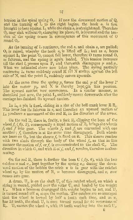
tension in the spiral spring 0^. If now the downward motion of Q.and the turning of L to the right begins, the hook o-; is first
brought to bear against L^ while the chain O3 is straightened. Therefore
O3 may sink without Oo changing its place; O4 is lowered and the ten-
sion of the spring ceases in consequence of this movement of
round Oo,
As the turning of L continues, the rod 0^ and chain O3 are pulled;
O2 is raised, whereby the hook Or, is lifted off Lj ; but as o^ bears
against Li the point O3 cannot fall lower, therefore turns round O3
as fulcrum, and the spring is again loaded. This tension increases
till the stud /. presses upon Pi and therewith disengages /; and j)..
What we intimated above now takes place. The spring partially
contracts; L^ turns suddenly round M till N strikes against the left
side of Ni and the point L3 suddenly moves upwards.
At the same time the spring p^ forces the end p of the lever Pinto the corner p..) and N is thereby keptj^in this position.
The upward motion now commences. In a similar manner, as
described just now, the point L3 suddenly moves downwards after the
carriage has finished its upward motion.
In L3 a pin is fixed, sliding in a slot of the bell crank lever E R,.
This lever has its fulcrum in r, and therefore an upward motion of
L3 produces a movement of the rod R3 in the direction of the arrow.
On the rod Ro there is, firstly, a fork P3 clipping the boss of the
wheel /s ifig. 3), consequently a rapid motion of R2 brings the wheels
/o and / into gear. The wheels /^ and /i are connected with one
another; /^ therefore is at the same time disengaged. Both wheels
are loose on G-o, but the sheave /o is fixed on it. This sheave reaches
with two studs through the body of the wheel /], so that in this
manner the motion of/i or/o is communicated to the shaft Go- Thedirection in w^hich Go and with it of/3 and/g revolve, therefore is alter-
nating.
On the rod Pto there is further the boss U (fig. 4), with the twocatches u and u^, kept together by the spring tio-y during the down-ward motion of the bobbin the catch u is in gear with the ratchet
wheel Uo', by the motion of R> w becomes disengaged, and u^ nowcomes into gear.
A drum, Uo, is on the shaft U, of this ratchet wheel, on which a
string is wound, guided over the roller U. and loaded by the weight
U4. When ic becomes disengaged this weight begins to act, and U^is turned round till u^ stops the motion. The catches are so arranged
that the wheel is turned by half a tooth each time, and as u^
has 23 teeth, the shaft U, is once turned round for 4G reversions of
R.. Ui carries the wheel ic^ with 48 teeth working into the rack U^,

iJ.S
which is connected to the strap guide for the two cones. The rack
has 48 teeth for every 12^ inches, so that after 46 reversions the
12,375 ^ „ _„ .
strap has shifted 12| inches, or for each reversion —^ = 0,269 m.
30
As the cone has a length of 30 inches, ^9 = lU reversions will
take place, and accordingly 111 layers of thread will be wound on till
the strap has finished its course.
The shaft Ui carries another wheel ih with 16 teeth, working the
rack Uc; the latter has 16 teeth in 3| inches, and therefore moves
during 46 reversions of E, o| inches, or for_ 111 a length of
luX s,625 ^ 8,747 inches, for one reversion 7^ = 0,0788 in.
Connected with this rack is the sliding pin Qi and consequently the
distance of Q^ from M, or the effective length of the rod Q, is altered
by the rack.
If the length of the vertical movement of Q2 remained the same,
a shortening of the rod Q would cause the oscillation of the piece Lromid IM to increase. But as the levers P Pi do not alter their posi-
tion, this quicker oscillation of the piece L causes the reversion to
take place sooner, and the length of the vertical movement of Q2 is
reduced in the same proportion as the length of Q grows less.
The machine is further provided with a self-acting stopping
apparatus.
54 on Fig. 5, PI. YIIL is a rod connected to the strap guide for
the driving pulley of the machine. The bell crank lever S3 s^ is fixed
on this rod, and oscillates on the pin U3 of the pulley for weight U4.
This lever has a projection s.. at its side.
A rod s is connected to the point L3 so as to share its jerking
motion; s-^ is a spring preventing the rod s to strike against s^.
The rack Ur carries a pin S, which as soon as the strap has got
to the end of the driving cone, presses the rod s against the spring s,
and overcomes its resistance. If s now is jerked upwards, it knocks
ao-ainst the projection s.; the lever is turned round U3 and ^le rods,
is'moved in the direction of the arrow, whereby the strap \Y (fig. 1,
Fl VII.) is guided from Wo upon the loose pulley Wi.
Fir/ 6 PI YIII, shows the lateral movement of the slubbing on
entering the back rollers. V is a bar, guided horizontally, and having
holes ^Tr, through each of which the ends of the slubbings ot 2
bobbins are passed, and thereby the place at which they enter the
rollers is determined. M forms the fulcrum of a lever \i connected
with L, and sharing its oscillating motion. It carries a stud v, a.

50
its end ; while another stud v^ is fixed in the bar Y. Both studs
slide in slots of the lever Vo, swivelling on v^. By this means the bar
V shares the lateral movement of I'l, multiplied by the ratio of
leverage ; it moves of course horizontally, in consequence of being
guided. The slubbing accordiugiy moves to and fro between the
rollers, whereby they are used on a larger width, and wear moreevenly and slowly.
For the purpose of removing the bobbins when they are full, the
spindles are turned backwards by hand by the wheel Wg. The bear-
ing for the top of the driving cone is then lifted by a lever, and the
strap becomes slack. The shaft Ui is then turned round backwardsway by the wheel Ug, whereby the weight U4 is wound up ; the strap
for the cones is shifted back to the base of the driving cone, and fmally
Qi is brought back into the position shown in Jig. 1. Then emptybobbins are put upon the spindles, and the winding on is started
afresh.
The particulars given above about the number of teeth on the
change wheel, the wheels on the draw-box rollers, &c. are taken from a
machine spinning No. 4, ie.j 4 hanks of the rovings weighed 1 lb.,
and as the draught was 7,44, the number of the slubbing supplied to
the machuie was _i— ~ —^ — 1,0757,44 7,44 ~2
In order to spin from this slubbing from the intermediate frame a
finer or coarser number, the draught between the rollers must bealtered. This is done by changing the two wheels Co and c^. If
instead of these wheels of 28 teeth, others of 06 are put on, thelength of the slubbing taken in by the back roller per minute vfill be
00,58 X 36 X 36 X 3,925 — 91,4 inches.yo X 56
The spindles winding on 418,179 inches, as before, the draught
becomes "^-IMI? = 4,58—and the number of the roving delivered
will be ^ X 1,075 = 2,46.
Or, a hank weighing in the first case | lbs. = -i^ grains, and 1
ley i^^ = 250 2'rains : the same length now will weigh ill^--•^4X7 &» o '=7X 2,46
= 406,5 grains.
Thereby naturally the diameter S of the thread has been in-
creased, the velocity v of the bobbin carriage must therefore be

CO
correspondiugly increased. This is done by replacing the pinion j\
by another having more teeth.
For /ii,with 16 teeth, the shaft H made at the commencement
of the first layer 1 ,004 revolutions, and the vertical motion of the
bobbin was 6J inches per minute. If we take a pinion /^ of 18 teeth
instead, n for H becomes
127,88 X 6 X 26 X 12 X 17 X 18 — \yZ3 X 48 X 100 X 50 X 90
'
and correspondingly v increases to 7,59 inches.
As further the increase of the rotatory velocity of the bobbin
for each new layer, as well as the length by which the vertical
motion of the bobbin has to be shortened, are depending on ^, an
alteration in these two points has to be made. This is done by re-
placing the ratchet wheel u. by one with fewer teeth. By taking, for
instance, one of 20 teeth instead of 23, Ui will be turned round once
in 40 reversions. Therefore the strap on the driving cone will be
shifted for each reversion IM!*^ — 0,309 inches, and the total number
of layers becomes -^ = 97.•^ 0,309
The point Qi now moves 8,747 inches for 97 reversions, or
?:!1I = 0,09 inches for each.97
'
Eegarding the intermediate frames, the difference consists, firstly
in the bobbins being made larger. If the first layer is to cover for in-
stance a length of 10 inches, the studs l^ must be so adjusted that the
end p of the lever P is disengaged as soon as Q^ is lifted 5 inches
above the middle position on the centre M. The studs are therefore
screwed, and their length can bo altered.
The driving shaft of the intermediate frame best makes 200revolutions per minute. As long as no change in the wheels is made,the number of revolutions of any revolving part of the intermediate
ft-ame is to that ofthe corresponding part of the roving frame as 250:
350, or as 5 : 7. Thus, for instance, the circumferential velocity of
the front roller is _i- X 355,5 = 253,9 ; that of the bobbin at the7
commencement of a new bobbin A x 887,85 = 634,18.
As the roving spun on the intermediate frame is much thicker
than that from the roving frame, a much larger weight of cotton is

wound in the same time upon the former than the latter. In order
not to lose too much time by the frequent removal of the full
bobbins, they are made correspondingly larger than for the roving
frame. Naturally this causes the spindle to be subject to stronger
vibrations, and to avoid any change of form it must be made stronger.
Besides the spindle is made to revolve slower in order to diminish
these vibrations, while the diameter of the bobbin is increased, so
that the winding on can take place at the same rate as before.
According to the proportion 5 : 7 the spindles would make
^ X 1000 — 714 revolutions per minute. If they are now made to
revolve slower, while the bobbins continue to make 634,18 revolu-
tions per minute, the length L would grow less than the velocity of
the front roller, if the bobbins retained their diameter of 1j\ inches
as on the rovino; frame.
To avoid this, the following changes are made :
The bobbins receive a diameter of lj\ inches, = 1,4375 inches,
so that their circumference is 3,14 x 1,4375 = 4,51365.
The wheel a is made with 32 instead of 33 teeth. This makesthe number of revolutions of the spindles
,„ ^ 250 X 32 X 60 ^ gc)2g3\s) 33X21 '
/^) — z^) now becomes = 692,63 — 634,18 = 58,45, and
L = 58,45 X 4,51365 = 263,8.
The draught between front roller and bobbin is in this case =
^^8 = 1 04;
253,9 ' '
while the number of twists per inch is
692^ =r 2,54.263,8
The number of teeth of the ratchet wheel Un depends of course
upon the thickness of the slubbing s ; if the machine with a draughtof 6,57 is to deliver thread of number 1,075, this ratchet wheel has
17 teeth, corresponding to a full bobbin of ^^ ^JL — 82 layers.
The slubbino' frame is driven at 220 revolutions ; therefore the
spindles make 609,5 revolutions—the arrangement being the same as
on the intermediate frame. The dimensions of the bobbins are
generally the same, therefore the ratchet wheel must have less teeth
on account of the greater thickness of the slubbing.

62
For the intermediate and roving frames, the bobbins from which
the slubbing is fed between the back rollers, are put on bars in a
creel, and turned round l)y the thread bein^: pulled off. For the
slubbing frame, there is before the back roller another roller of
about Sin. diameter, driven at the same circumferential speed as the
back roller, over -which the web is led from the can.
The number of spindles of a machine depends upon the fineness
of the yarn to be delivered ; for slubbing frames it is 40 to 114 ;
for intermediate frames 48 to 160 ; and for roving frames 72 to 200.
SELF-ACTING MULE.
For converting the rovings delivered by the preceding frames into
yarn, three different machines are used: Throstles, self-acting mules,
and hand mules.
On the throstle frames the coarsest numbers up to No. 40 can bespun, but they are rarely used for higher numbers than 30. In the
same manner the self-acting mules are applicable from the coarsest
numbers up to 11 0, but they are seldom found in use for finer num-bers than 80. The finer yarns are spun on hand mules.
The throstle yarn is in comparison to the mule yarn more uni-
form, consequently better. On the contrary, the outlay of capital as
well as the wages are higher for a number of throstle spindles thanfor the corresponding number of mule spindles, the produce being the
same, therefore the throstle yarn is dearer to manufacture. For this
reason with the exception of a few special purposes (as turkey-red
dying), mule yarn is used in greater proportion, and these machineshave almost entirely superseded the throstles, at least the construc-
tion of new throstles is comparatively a rare occurrence.
There are two kinds of yarn to be distinguished; twist and weft.
The former is used for warps, sewing and knitting cotton; the latter
only for weft, i. e. filling up the warps. Twist compared to weft of
the same number shows greater strength; it is made of better mate-rial, and has more twists per inch of length.
The number of twists per inch depends upon the length of fibre
of the cotton employed. If the quality of cotton suitable to thenumber is used, it may be taken as a standard that No. CO of twist
and No. 80 of weft must have each 28 twists per inch, both yarnsbeing made of the same material.

63
If the number of the yam is called N, and the number of twists
per inch n, we have as a rule for twist
« = V(28)^^
60
And for weft
V (28) ^ N80
Thus for instance, for No. 32 twist the number of twists is
__ ylllHJiXIL ^ V418 = 20,445
And for No. 40 weft,
^^ ^ ^i^y^jL^^^ ^ V392 = 19,8
If worse raw material, i. e. material of a shorter fibre than that
corresponding to the number of the yarn, is used, the nnmoer of
twists thus obtained must be increased in order to attam the reqmred
firmness of thread.
The self-acting mule consists of several fixed and one moveable
part- the former are the headstock, occupying about the middle of
the machine; the beams on both sides of it servmg as frame for the
drawino- rollers; the creels, for receiving the bobbms from the roymg
frame, ""marked x' on the drawing. At each end of the machme
there is a side piece parallel to the neadstock. Besides this a num-
ber of rails, friction pulleys, etc., are fastened to the floor, which will
be described in their proper places. The moveable part is the carriage,
on which the spindles are placed in a row, interrupted^ by the head-
stock and parallel to the draw box rollers. This carriage rests on
wheels K, and runs in and out on rails, during which movement it is
kept parallel to,its original position by a special contrivance.
The spinning process of a self-acting mule is about as follows:—
The rovino-s obtained from the roving frame are stretched by
three pair of draw box rollers and receive the required number of twists
bv the rotation of the spindles. During this time the carriage tra-
verses out. It then runs the same way back, while the yarn spun
dm-ino- the running out is wound upon the spindles m cops ot cyim-
dricafshape, with conical ends {fig. 10, PI XL) One stretch, i.e.
the making and winding on of a length of thread equal to the length
of traverse of the carriage, may be divided into 4 periods :
1st—Uurino- the first period the carriage moves outwards; the
draw box rollers'supply yarn, which the spindles twist. In consequence

C>4:
of the inclined position of the spindles the yam slips oyer their ends
and no winding on takes place.
It may here be remarked that for the sake of avoiding the forma-
tion of loops the speed of the carriage must be greater than the cir-
cumferential Telocity of the front roller. The difference during one
trayerse is for No. 30 = 2 inches; for ISTo. 50 = 3 inches; for No.70 = 4 inches, &c.
2nd,—The drawing motion is stopped, the spindles continue to
revolve, the carriage moves to the end of its traverse, whereby the
already twisted yarn receives an additional drawing. This subsequent
stretching increases with the fineness of the number. For yarns be-
low No. 40 this second period falls out entirely; the drawing motion
is not stopped until the carriage has reached the end of its entire
traverse of 60 to 6G inches, at which moment the yarn has already
received the required number of twists.
3rd,—The spindles are now turned backwards way, so that a
short length of yarn is unwound while the copping wire is lowered,
and so brings the thread to the spot on the spindle where the wind-
ing on is to begin.
4th,—The carriage runs in while the spindles revolve so often
that a length of thread equal to that of the traverse is wound on.
The time required for each stretch is about 20 seconds, so that in
every minute a length of 3 X (64in. on the average) is wound uponeach spindle.
The various motions here occun-ing, each of which is produced by
a special mechanism, are the following :
—
1. The di'awing-out motion of the carriage.
2. The taking-in motion of the same.
3. The revolving motion of the drow box rollers.
4. The revolving motion of the spindles during the twisting.
5. The turning back of them (backing off motion.)
6. The revolving motion of the same during the winding-on.
These motions are all periodical, and are thrown in and out of
gear by a cam shaft.
A (PI. lY, X, XI) is the driving shaft making SCO revolutions
per minute, B the cam shaft, C the shaft for the drawing-out motion
of the carriage, called back shaft ; Cj the shaft for taking in the
carriage; E the front roller; F the tin-roller shaft, carrying the drum
Fi from which each spindle is driven by a separate band.

65
On the shaft A are the driving pulley Aj, and the loose pulley Aq.
The width of the strap is such that when it is running full on the
pulley Ai it also drives Aq, so that as long as the machine is not
stopped Ao and the parts di'iven from this pulley are in continual
rotation. Usually the shaft A is driven from a counter-shaft or driv-
ing apparatus, and this is thrown out of gear when the mule is to be
stopped.
r is the strap guide, fixed to the bell-crank lever R oscillating
upon r^. A pin Tq is fixed on the strap guide which is pressed against
the piece Wj, fixed on the shaft B, by the spiral spring ^3, one end of
which is fastened in i\ to the lever R, while the other i\ is fastened
to the machine frame. The piece m^^ is a cylinder cut out in a pecu-
liar manner; {Fig. 6, PI. XI. j shows it flattened out and at the sametime the positions of the pin ^o for the 4 different periods. Duringone stretch the shaft B is turned four times, each time by 90 degrees.
The position I of the pin ^o corresponds with the position of the
strap in fig. 5. Daring the second period the strap has already
moved towards the loose pulley, while during the third and fourth it
runs fally upon it. To retain the pin during the 4th period in the
mentioned position the bell-crank lever oscillating upon r-^ is used.
It has two set-offs, the second of which counted from the fulcrum
stops the pin ^4 during the 4th period, while the first one stops it
during the 1st period ( Fig. 1, Fl.X.) The other arm of this lever
carries a small plate Tq; r^ is a knocker fixed to the carriage, whichknocks against Tq when the carriage runs in. Thereby the lever is
turned upon r^ so much as to let the pin r^ loose ; the spring r..
moves the lever R to the left till ^4 is caught by the first set off,
whereby the strap is brought back into the position occupied during
the first period.
On the shaft A there is also a pinion a (t = 21) driving by a
carrier wheel «i the wheel a^ {t = b2) or the shaft Eq; the latter
carries the bevil wheel a^ {t = 27) driving the wheel a- {t = 42) on
the front roller E.
360 X 21 X 27The number of revolutions of E therefore is = —52 x 42
~~
= 93,46.
The diameter of E is = lin., consequently its circumferential
velocity = 8,14 x 93,46 = 293,46.
The front roller is therefore stopped by the strap being guided
upon the loose pulley, but as the shaft A is turned backwards wayduring the third period, and as the front roller must not share this
motion, the wheel a^ is loose on E and provided with a clutchbox, so
that the roller is only turned as long as this clutch is in gear witH
the corresponding one, which is feathered on E, so as to allow it to
F

slide ill tlie longitudinal direction of E. The throwing in and outof gear is effected by the disc / keyed on B. A groove is cut into
the back side of / {Fig. 1, PI X, Fig. 3 and 4, PI XI) in which the
pin /i slides, forming one end of a lever swivelling upon 4 ; the other
arm of the lever ends in a fork /j fitting into the groove on the catch
box on E. During the first period, the pin t^ and disc t occupy the
position Fig. 3, PL XI. As soon as the shaft B is turned to the
right the pin t^ will be forced nearer to the centre and make a move-ment to the right, whereby the fork is moved in the opposite direc-
tion and the clutchbox is disengaged.
On the shaft Eo there is also a pinion a^ (/ = 18) which drives by a
carrier wheel a^ the wheel ct-^ (t = 69) on the shaft Cq ; a pinion a^
(t =^ 14) on the latter drives the wheel ccc^ (t = 44) fixed on the shaft
C—
,.0fC= 36 X 21 X 18 X 14 _ i2,0652 X 69 X 44
'
This shaft carries near its middle the grooved pulley c, and at both
ends the similar pulleys c^ and c^. Their diameters are 8in., their
circumferential velocity 3,14 X 8 x 12,06 = 302,94.
A band, one end of which is fastened to the carriage at h^, passes
round c and over the pulley c. on the shaft H, and is fastened at h^ to
the carriage. The band pulleys {PL XII, F'igs. 11 d; 12) are volute at
their ends, whereby an accelerated motion of the drawing-out motion
can be produced, in order to facilitate the joining of their broken
threads.
Their width however is so large that the part between the volutes
or scrolls can be used only, and the speed of the carriage can thus
be kept uniform. The scrolls ^^ c^ correspond with the sheaves
c. c^^ that have their bearings in the fixed side pieces ; each of the
bands passing over them is fastened with both ends to the carriage.
By this means the carriage receives a velocity of 302,94 inches,
while that of the front roller was 293,46 inches. The time required
for a traverse out of 66 inches is consequently only 14 seconds, and
the carriage gains upon the front roller (302,94 — 293,46) X ^ =60
^'i^ XJI4 ^ 2,2 inches.60 '
For the same reasons we mentioned with regard to shaft Ed the
wheel ttc, is loose on C, and furnished with a catch box, which must
be in gear with the corresponding box sliding on C, il the latter is
to be turned. For this purpose the disc ?/. on shaft B is grooved. Thepin u^ sliding in this groove forms one end of the lever turning on ?^o.

G7
while the other forked end a^ clips the catch box on the shaft C. Inligure 7, PL XI, it and u^ are shewn in this position during the first
period, when the clutches are engaged ; as apparent from the draw-
ing, they will be disengaged during the followmg three periods.
The pinion h {t = 22) is fii-mly keyed on the long boss of the
pulley Ao running loose on the shaft A, and gears with the wheel b^
{t = 34), connected to the latter is the pinion 1)., {t = 2-1) driving
Z?3 (^ z= 51), keyed on the same shaft with the latter is the bevil-
wheel dr {t = 20) driving />§ (i = 27) on the oblique shaft 0.. Thelatter carries the pinion Z'g (^ = 19) gearing with &;o (^ = 37) on
the shaft Ci-
n0fC,= 360 X 22 X 24 X 20 X 19 ^ 4^734 X 51 X 27 X 37
The pinion b^ is loose on Co, and carries a he-friction-cone at its
back. The corresponding she-cone slides on Co with a feather andgroove, and if sufficiently pressed against ^^o, will take it round andthereby turn the shaft Ci-
On Ci two scroll pulleys c^ and Cq are fixed ; upon each of which aband is wound by the revolving motion of Ci. The 1:)ands are
fastened at h^ and Ii^ to the carriage, and thus take it in ; c^ is asimilar pulley, but fixed on Ci in the opposite way to ^5 and c,j. Aband wound round the latter passes over r„ and its two ends are
fastened at h^ and h- to the carriage. By this pulley the shaft 0^ is
turned back again during the drawing-out of the carriage.
In consequence of the volute shape of the pulleys c^ and Cg, the
taking-in motion of the carriage is at first slow, then increases in
speed till it reaches its maximum, and diminishes again towards the
end. The reason for this will be shewn later on in speaking of the
winding-on of the threads ; the decrease of the velocity at the sametime serves to prevent a violent shock at the end of the traverse ofthe carriage. The greatest speed corresponding with the largest
diameter of the volute of 11 inches is
3,14 X 11 X 41,7 = 1440 inches.
The friction coupling is thrown in and out of gear by the disc ti.
Another pin w^ slides in the groove of the latter, and is fixed to a
lever oscillating on ic^ ; a rod V is joined to Ur^ at one end, and at
the other end to a lever turning on iIq, and clipping by its other
forked end the she-cone on Ci. If B, and therewith u, is turned for
3 X 90 degrees, the pin u^ is lifted : u- shares this motion, wherebythe rod U turns the lower lever round u^, and brings the frictio]i
cones into contact, which is again dissolved after u has made a farther
revolution of 90*^. The coupling consequently is engaged only duringthe 4th period.

68
The spindles are made to revolve during the twisting in the fol-
lowing manner:—The pulley/ (called the rim) with a double-grooved
rim of 22in. diameter is keyed on the shaft A; /, /j, / are pulleys
fixed to the framing; 74/5 the same at the other end
; / {d = lOj
a pulley fixed on F. The drum Fj on the shaft F has a diameter of
6 inches, and the pulleys or wharves fixed on each spindle iin.
The double band running over /, first passes over /, then over
/s, and back upon /, from that upon /, and back again to /s, then
upon / and /g, and back unto /. To keep it tight the sheave J\ can
be adjusted in a horizontal dh'ection.
The number of revolutions of the spindles consequently is
360 X 22 X 6 ^ g33g10 X 0,75
Or, for one revolution of the rim /—
•
22 X 6
10 X 0,75= 17,6
The velocity with which the caniage traverses out is 302,94, the
number of twists per inch therefore is
_^l__ = 20,9 (No. 32 twist)302,94 ' ^ ^
This twisting takes place during the 1st and 2nd period, and is
stopped by the strap being guided upon the loose pulley, which is
done by w^4, in connection with the levers R as shown above.
The backing ofp motion of the spindles during the third period is
produced in the following manner :
—
A pinion ki{t = 15) is keyed on the same shaft with d^ and h-,
gearing with d^ {t = 82) ; the latter turns loose on A and makes360 X 22 X 24 X ^5
34 X 51 X 82~ 20,05 revolutions in the opposite direction
to the strap. Fixed to the body of this wheel is a friction rim,
reaching inside the rim of the pulley A^. If this friction-coupling
is engaged, I)-^ will take the pulley Ai and shaft A round with it,
whereby the spindles ai'e turned in a direction opposite to their
former revolutions.
The engaging is effected by the cam t on B. It has a projecting
rim with a piece cut out in one place {Fi(/. 5, PL XI), against the
edge of which rim the pin 4 is pressed ; t is fixed in a lever that
has its fulcrum in 4 and carries a fork 4 fitting in a groove on the
boss of the wheel d^, while the other end of the lever is pulled to the

6\)
right by ii spiral spring /-, fastened at 4 to the framing. If I is
turned so far that L comes to the notch, the spring exercises its influ-
ence and turns the lever upon 4> whereby the friction-surfaces are
pressed together. This backing-off motion of the spindles takes
place with a velocity of 20,05 X 17,6 = 35o revolutions per
minute.
The spindles are turned dui'ing the winding-on or copping in the
following way
:
H is a shaft parallel to C, on which the grooved pulley h is
fixed; the band running round the latter is passed over the sheave h^
fixed on C, and its ends are fastened at h^ and h^ to the carriage.
H carries a pinion k (t = 17) gearing with the quadrant Iq. Dur-
ing the dra^ving out of the carriage the quadrant is turned to the
left by k, and during the taking in it makes the same way back to
the right. Jci oscillates upon Jc^, and contains a screw in one of its
end arms, having a httle handle at the top by which the workmencan turn it. A little ratchet wheel and click fixed respectively to
the screw and ki keeps the former in its position. The slide block
^2 forms a nut on the screw, and can be moved up and down byturnmg the latter. / is a lever oscillating upon l^ with a small plate
4 and a moveable stud l^,. h is a stud fixed in the framing, against
which 4 strikes when the quadrant is turned.
Fo is a short shaft having its bearings in the carriage. The bandpulley % the chain drum Jc^, and the wheel Jc^ {t = 68) are keyedfast upon it. ij^ is a pulley on the carriage; 4 a half round sheave
fixed to the floor. It oscillates loosely on its pivots, but is turned
to the left by the weight %• A band fastened at % to the framingpasses over i and 4, the other end being fastened to 4'
7c-^ is a wheel loose on F (t = 24), fixed to it is the disc Z-^ carry-
ing a click ^g; Jc^ is a ratchet wheel keyed upon F; attached to the
click is a small triangular plate with two pins {Fi(/. 1 6 and 14, P/.
XI). A spring {Fi(/. 14) is fastened to a stationary boss placed onF; one end of it passes between the two pins and rests against the
stud of the click. If 7^4 is turned in the direction of the arrow, the
sheave Jcq revolves likewise, but the pin to the left of the spring is
stopped in its motion by the latter, and causes the click to turn onits pivot so as to drop into the teeth of the ratchet 7c^, which nowtransmits its rotatory motion to the shaft F and thereby to tlie
spindles. A chain is linked to 7c2, passing several times round the
chain drum 7c^, and is fastened to it by its other end.
When the formation of a new crop begins, the thread is woundupon the spindle itself or upon a cylinder of small circumference ;

70
every subsequent layer is wound upon the preceding one, conse-
quently tlie circumference of the cylinder upon which tlie thread is
wound continually increases. As the length of the thread, as well
as the time for taking the carriage in, remains constant, the numberof revolutions of the spindles during the winding on must necessarily
decrease if the breakage of the threads is to be avoided.
On beginning a new cojj h^ stands in its lowest position close to
/'o, so that the point in which the chain is linked to k^ describes a
very small arc round /^o* If we suppose this movement to be = 0,
or that hi remains stationary, a length of chain equal to the traverse
of the carriage, or 66in. is wound oft the drum Ico. The diameter of
li^ being 6 inches, the number of revolutions of the spindles is
66 X 68 X 6
6 X 3,14 X 24 X 0,75
66 being the length of traverse.
68 the number of teeth of Jc^,
6 the diameter of Fj.
6 X 3,14 the circumference of /'s-
24 the number of teeth of h-^.
0,75 the diameter of the wharves on the spindles.
We will now suppose Ic^ to be in its highest position {Fig. 1, PLIX.) When the carriage has reached the end of its outward tra-
verse, the point Jc^ stands nearly vertically above the shaft H, while
at the end of the taldng-in the quadrant has been turned so much to
the right that the piece of the chain from Z", to the drum is in a
nearly horizontal position. It is now evident that the effectual
length of the chain causing the revolutions of the drum is now 66
inches, less the horizontal projection of the arc described by 7^2. Bygradually moving the slide block h. from its lowest to its highest
position, this length to be deducted is gradually increased, and
thereby the rotatory motion of the spindles reduced in speed. Whenthe cones of the cops which are first formed on the spindles have
attained the size of the cylindrical part of the finished cops, a state
of permanence begins, the spindles making after that time always
the same number of revolutions during the taking-in. The screw
for moving h^ is turned by hand; various apparatus have been em-
ployed to make this regulation self-acting, but according to inquiries
made of a great number of workmen in different mills, the workmanalways has still to correct this regulation; so that until now nothing
else has been achieved by the self-regulating motions, but that the
workman has to turn the screw a few times less.

71
While tlie carriage is drawn out, the shaft Fq is turned by tlie
string i, whereby the chain is wound upon the drum as far as the
quadrant allows this to be done. The circumference of the pulley
'/ has the tendency to revolve with a circumferential speed of 6 Gin.
But as this velocity is retarded by the chain, the string begins to slip
on /, overcoming the tension exercised by the weight 4.
The winding-on begins {Fig. 9, PI XI) at v^, goes down to ?^,
and then up again to v., ; then the thread is slung a few times roundthe part of the spindle from v.^ to the end. Accordingly at first the
circumference of the body on which the thread is wound increases
till it has reached its maximum, equal to the circumference of the
cyhndrical part of the cops, and then gradually diminishes again.
The relative velocity of the point where the winding on takes place
must however be constant ; or, in other words, the rotatory velocity
of the spindle must begin accelerating, and diminish again after
the maximum has been reached.
These changes are effected by the following combinations :
In consequence of the volute pulleys c^ c^, the carriage movesduring the taking-in with increasing velocity, which after havingreached its maximum, decreases again, as already shewn.
The actual rotatory velocity of the spindles is besides retarded
by the oscillations of the quadrant in a varying ratio. The retard-
ation is greatest when Ic, stands vertically above Ic^ ; at this momentIc, moves nearly horizontally and parallel to the directions in whichthe drum moves ; the chain gives way a great deal, whereby the
I'otatory motion of the drum is retarded, its circumferential velocity
lacing as shown above, at every moment equal to the velocity of the
carriage, less the horizontal projection of the arc described by Icn. If
the quadrant is turned round as far that h moves nearly in a vertical
line, which takes place towards the end of the traverse—in this
horizontal projection is nearly equal 0, therefore nothing has to be
deducted from the velocity of the carriage, and the circumferential
velocity of the drum Jc. is equal to the former.
It is evident that the amount of this retardation increases fromthe beginning of the taking-in, up to the moment when k. stands
vertically above Zr,,, and decreases from there towards 0.
The apparatus marked / serves to effect a retardation of the
spindles during the period the threads are wound on from Vo, towards
the end of the spindles, causing them to be loosely put round the
spindles. It only comes into operation after h, has attained its high
position, and consequently the cop has attained its greatest diameter.
When the quadrant has nearly reached the end of its oscillation, the

72
plate l^ strikes against the pin ^4, whereby the lever I is turned uponits fulcrum ; the pin h depresses the chain, and thereby causes the
required retardation in the speed of the drum.
MOTION OF THE CAM SHAFT.
Jg is a wheel turning loose on B, taken round by Z>5, and provided
with a clutch box m. The piece m^ m.^ is connected to B by a feather
and groove, m^^ being a catch box corresponding with w, and m.^ a disc
with 4 teeth or stops on its face. These teeth (Fig. 1 and 2, PI.
XI), are at different distances from the centre of the disc, m^ is a
lever oscillating upon m^^ and ending in a tooth niQ which slides uponthe diso. m^ is a spiral spring compressed between m^ and m.2. If
the tooth niQ moves a little to the right, the spring m.^ pushes the
disc w?'2 towards Z^g, whereby m and m^ become engaged, and the shaft
B is turned round. The tooth mo now slides upon the disc at such
a distance fi*om the centre as to come against the stop No. 2 after
one quarter revolution, when nu is arrested and slides back; the
clutch box is thrown out and the shaft B is stopped after turning
OO*^. At the end of the second period the tooth m^ is again moveda little to the right, the catches become engaged, and another quar-
ter revolution of B takes place, till Wq is caught against the stop
No. 3. In this manner the shaft B makes at the end of each of the
4 periods a partial revolution of 90 degrees, so as to make one en-
tire revolution during each stretch.
L is a lever (long lever) oscillating upon Lj ; one end of it Lq is
linked to the lever 711-^ at w^. Joined to Lo is a bell crank lever,
swivelling upon Lg, and carrying a small plate L4, acted upon by the
friction roller L5 fixed to the carriage. The other end of the lever Lis loaded by the weight Lo, and pulled down when there is no obstacle
in the way. L3 is a stud fastened in L.
L; is a pin fixed to the framing and sliding in a slot of L, so as
to limit the oscillating motion of L.
N is a shaft having its bearings in the framing, on which a
bell-crank lever is keyed on ; one arm carries the friction roller W5,
whilst a spiral, fastened at W4 to the framing, is attached to the other
arm n^. The hook 7I0 is likewise keyed upon N, while the lever n^
is loose upon it, and is provided with a set-off and small knock
plate.
w is a stud fixed in L, which is held up during the 1st period by
the catch n^. n- is a knocker fixed to the carriage, striking against
the knock plate on n^.

73
?^g is a lever with the knocker u^q ; n^ ti corresponding plate fixed
to the framing. The lower end of this lever is provided with aroller n^, connected at the Scime time with the lever k^f^, oscillating
upon k^j.
is a curved lever keyed upon v/, ending in a small surface, cor-
responding with the set off on n^. 71q is a cranked lever with a slide
surface at one end, and linked with the other to n^. It oscillates
upon^f and hj. the link causes the n^ to oscillate upon Uq. (Fig. 13,
PL XI.
Oa is a bent plate to which a chain is attached at o^. Anotherlever oscillates upon o^, carrying at one end pulley o^, at the other a
plate Oj ; O5 is a weight having the tendency to move the pulley c?^
round 0^ towards the left.
Oq is a friction pulley corresponding with o^, carried by a lever
oscillating upon Oiq. This lever is linked to L by the rod o^ o^^i so
that Oq moves up and down with L2.
7cq is a sheave turning loose upon F, h^i a click; Ic^^ a ratchet,
k^^ a pin on a lever oscillating upon Jcj^^ and linked to Jc^q, so that a
downward movement of Ic^r^ moves the pin k^^ to the left. ki2 is a
cpm turning loose on the shaft F and resting against the pin k^,^,
while the pivot of the click rests against the cam. ^13 is a spring throAv-
ing the click in and out. An eccentrically grooved pulley is attached
to the sheaf kg, upon which the chain fastened to O3 is wound. This
chain passes over O2 and (?4 and is fastened in Og to the sheaf kg. If
the pin k-^^ is moved to the left, it will prevent the sheaf kg fromretm-ning to its former position, and detain it in one more to the
left. Thereby the eccemric grooved pulley is turned so that the
chain is now wound upon a large diameter. This causes the windingon to be accelerated, so that the shaft G- is turned more rapidly to
tiie right, whereby the copping wire is lowered more quickly, as will
be described farther on.
The process now is the following :
—
During the traverse out of the carriage, Lq is in its lowest
position; m^ rests against the stop No. 1 on disc Wg; all parts are in
the positions shewn in Fig, 1, Fl. X.
When the carriage approaches the end *of its traverse, the plate
7ir, comes under the friction roller ?i-; the latter is lifted, causing atension of the spring ji^ n^ and a movement of the hook n^ so as to
bring it under the pin n. The carriage progressing, n-^ strikes
against a plate on n^, whereby the pin n is released. (To prevent nfrom moving too far, a small pin d is fastened in the frame whichlimits this movement.) The weight L3 now begins to act
G

74
and sinks down ; this causes the pin L. on the other end of the
lever to come against a stop not shown on the drawing.Thereby the lift of the end Lq is limited, so that the tooth
iHq only moves so far as to come against the stop No. 2 on the disc
m.; and the shaft B makes a quarter of a revolution. The strap
is shifted into the place determined by the position II of the pin ^o Fir/.
6, PI XI, that is to say a little towards the loose |mlley, but still
driving the driving pulley. The draw-rollers and the drawing-outmotion are thrown out of gear, wdiile the spindles continue to revolve.
The catch supporting Lg is withdrawn by the worm wheel a.^, as
soon as the twisting is finished, which period may be lengthened as
required by altering the ratio of the wheels.
As soon as Lg is let free the weight L3, again lifts the ends Lo,
till the pin n is caught by the hook n^. The tooth m^ comes after
another quarter revolution of B against the stop No. 3 on m.2, and
the third period begins. The strap is shifted upon the loose pulley
and the spindles are stopped. But at the same time the friction
cones h^ A^ are engaged; therefore the shaft A and the spindles turn
in the opposite direction. By turning the shaft F in the opposite
direction, the spring Tc^^ is taken round, and pressing against the
little pin, brings the click ^n between the teeth of Tc^^^. This causes
the sheaf Tc^ to revolve and to wind the chain on its grooved pulley.
This at first makes the pulley O4 oscillate upon o^ till the plate o-i
comes against the roller O9, when the bent plate o^. must follow the
motion of the chain and the shaft Gr is turned.
Simultaneously with G- the curved lever is turned, which causes
its outer surface to slide against n^ till the set off on n^ is passed.
The spiral n^ n^ now begins to act ; n^ depresses n^ and % moves
to the right till it is again stopped against 0. The shaft N being
thus turned a little produces an oscillation of the hook n^ whereby
the pin n is again set free, and Lg again sinks down till the upper
side of the slot in L comes in contact with the pin L7. At the same
moment Oq falls so far as to let o^ free ; O4 immediately oscillates to
the right, whereby the tension of chain, and with it the motion of
the shaft G comes to an end.
The tooth m^ is again moved to the right so as to come against
the stop No. 4. The shaft B has made another quarter of a revolu-
tion, the coupling &- Aj is disengaged. The pin 7\ is stopped against
the second set off of the lever oscillating upon r-^, so that the pin Tq
cannot jerk back against m^ but is kept in the position IV. The strap
consequently remains on the loose pulley.
This last turning of B causes the pin u^ to be raised, whereby
the friction coupling ^'9 is engaged and the shaft Ci is made to revolve,

75
causing the carriage to be taken in. Tliei'eby the chain wound uponthe drum k^ is wound off again, causing the shaft Fq to revolve. Asshewn before h^ drives h^, and thereby the slieave k^. The click 1c^ acts
upon the ratchet and thereby turns the shaft F, and with it the
spindles for winding the thread on.
To the lever Uq for throwing the friction cones h^ in and out ofcontact, another lever-system 7^ is linked by the link^;^. A crankedlever oscillating upon 2h is connected by the rod p., to another bell-
crank lever swivelling upon p^ ; the latter carries a small catch 7;,
which retains the pin^^ that is fixed to the carriage. When u^ is
lifted 2^ is raised simultaneously, ^^o is set free and the carriage cantraverse in.
At the end of the fourth period L- knocks against L^; the lever
turns upon L^j and depresses L^; the tooth iUq moves in the opposite
direction and returns from the stop No. 4 to No. 1 ; r. also strikes
against r^, causing the lever to oscillate on r^ and to liberate the pin
?4. The spiral spring r^ now acts and moves the lever R round i\,
whereby Vq returns to position I, and the strap is guided upon Aj.
The pin i\ now rests against, the first set oir.
The knocker n^^, strikes ^/z ,1 ; the lever ^23 oscillates upon nc^ andreleases the end of the lever 0. The spiral spring o^o, Firj. 8, PI. XI,one end of vv^hich is fastened at s^ to the carriage, while the other is
attached at 5 to a lever keyed upon G-, the shafo G is turned backand the copping wire lifted. At the same time the sheaf /jg is turned
back.
By this last quarter revolution of the shaft B, consequently the
friction cones are thrown out of gear, the catch box for the front
roller is engaged by 4 as well as the catch box for C by v.y, the
spindles begin their twistmg motion and a new thread is started.
The ratchet x. fixed on B serves to retain the latter in its respective
position during the different periods. It has four teeth into whichthe pin Xr, works. This pin is carried by a lever oscillating upon x^;
to the other end x^ a spring is attached, fastened at x~ to the framing.
During a quarter revolution of B x- is depressed and the spring
loaded, so that it contracts as soon as the edge of the tooth is passed,
whereby x-^ is pressed into the next hollow. X is a handle for
turning B by hand.
THE WINDINCt on.
Z is the copping rail, resting with two pins 2.2 z^ on the copping
plates z and %. ^4 is a stud field in Z, sliding between the bars z^.
The bar z-^ connects z and z^. The screw z^q has a collar passing

76
through ^n? and its other head passes through a nut z^^ connected
with z. The lever z^^ oscillates upon z^q, and is linked to 4i by a
chain, di is a small lever keyed upon the axle of the quadrant, and
sharing its oscillating motion; z^ a small ratchet keyed upon z^q;
^c,aclick joined to Tjo; z^ a weight depressing the lever z^,^. If
^?i moves to the right, z^o sinks down in consequence of this Aveight,
but if dj^ is moved to the left z^^ is raised by the chain, the click acts
upon the ratchet and turns the screw 0ioj whereby z and z^ are
moved to the right.
X is a lever fixed on G, through the end of which the faller wire
passes; while o-j keyed upon Gi carries in a similar manner the counter
faller.
S is a weight oscillating upon a stud 5- fixed in the carriage; s^ a
chain pulley carried by the opposite end of S; 5o a lever keyed on G.
A chain fastened at one end to 5. passes round s^ and is attached to
',c^ at s^»
Si is a weight fastened below the carriage; S3 a chain pulley keyed
Gi; S4 another pulley turning loosely on a pin fixed to the carriage ;
Sq a lever keyed upon G; So an inclined plane, and S5 a friction roller,
both fastened to the floor. A chain is fastened to S^ at s^ and after
passing over the pulley S3 is attached to S4 at s^; a second chain
connects Sj and ^o*
The windmg-on is regulated by the movement of the faller wire,
while the counter-faller serves to keep the thread tightened.
During the drawing-out x occupies the position shewn in Fig. 1,
PJ. X; during the third period the faller is lowered to i\; during the
fourth period it gradually descends to v and then rises gradually to
^'2, when it is suddenly jerked back into its former position.
The place of t\ or the pomt to which the faller wire is lowered
during the third period depends upon the angle the shaft G is forced
to describe by the set off on n^ acting upon the end of 0; this depends
again upon the height at which the set off on 71^ happens to be. Bymoving z and z^ to the right, Z and with it the set off on 71^ is
lowered; this causes the faller wire to be lowered less and less; so
that the point Vi moves toward the top end of the spindle.
The motion of the faller wire rafter reaching t\, consequently
during the fourth period depends upon the shape of the rail Z, at the
beginning of this period Ug is near to z., and first rises rapidly corres-
ponding to the winding on from i\ to v; then the rail falls gradually
till near the end, where the fall is again more rapid.
The shape of the plates z and Zi is such, that on commencmg a
cop the rail Z is lowered very slowly at z-i but more quickly at Z3.
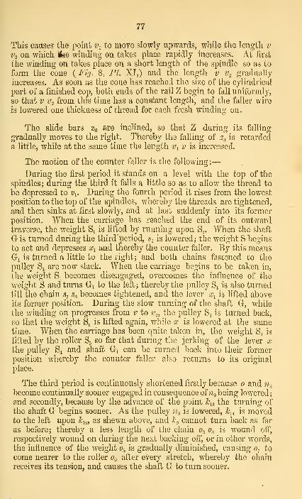
77
This causes the point v^ to move slowly upwards, while the length v
V.2 on which Ifiie winding' on takes place rapidly increases. At first
the winding on takes place on a short length of the spindle so as to
form the cone {Fig. 8, PI. XI,) and the length v v. gradually
increases. As soon as the cone has reached the size of the cylindrical
part of a finished cop, both ends of the rail Z begin to fall uniformly,
so that V V. from this time has a constant length, and the faller wire
is lowered one thickness of thread for each fresh winding on.
The slide bars z^ are inclined, so that Z during its falling
gradually moves to the right. Thereby the falling of z^ is retarded
a little, while at the same time the length i\ v is increased.
The motion of the counter faller is the following:
—
During the first period it stands on a level with the top of the
spindles; during the third it falls a little so as to allow the thread to
be depressed to v^. During the fourth period it rises from the lowest
position to the top of the spindles, whereby the threads are tightened,
and then sinks at first slowly, and at lasc suddenly into its former
position. When the carriage has reached the end of its outvvard
traverse, the weight S^ is lifted by running upon S_,. When the shaft
G is turned during the third period, s^ is lowered ; the weight S begins
to act and depresses o\ and thereby the counter faller. By this meansGi is turned a little to the right; and both chains fastened to the
pulley Si are now slack. When the carriage begins to be taken in,
the weight S^ becomes disengaged, overcomes the influence of the
weight S and turns G^ to the left; thereby the pulley S4 is also turned
till the chain s. Sq becomes tightened, and the lever x^ is lifted aboveits former position. During the slow turning of the shaft G, while
the winding on progresses from v to v.,, the pulley S4 is turned back,
so that the weight S^ is lifted again, while x^ is lowered at the sametime. When the carriage has been quite taken in, the weight S^ is
lifted by the roller S5 so far that during the jerking of the lever xthe pulley S4 and shaft G^ can be turned back into their former
position whereby the counter faller also retui'ns to its origmal
place.
The third period is continuously shortened firstly because and n^
become continually sooner engaged in consequence of ^^g being lowered;
and secondly, because by the advance of the point h^,^ the turning of
the shaft G begins sooner. As the pulley ;^i is lowered, Jc^^ is movedto the left upon h^^, as shewn above, and /c-., cannot turn back as far
as before; thereby a less length of the chain o-^ 0^ is wound off,
respectively wound on during the next backing ofi", or in other Avords,
the influence of the weight 0^ is gradually diminished, causing 0^ to
come nearer to the roller Oq after every stretch, whereby the chain
receives its tension, and causes the shaft G to turn sooner.

78
The second period falls out entirely for numbers up to 40, as the
requisite number of twists can be given to the yarn during the first
period; in this case the third period immediately follows the first.
The hook lUo moves from stop 1 to stop 3; consequently the stop 2,
the worm a-o and the pin L3 are deprived of their influence.
When the cops have attained the required size, the workman
moves them to the top end of the spindles while the carriage is at
the end of its backward traverse ; z and z^ are screwed back into
their former position by a handle placed upon 2:10; after disengaging
the click for the screw of the quadrant, the latter is turned backwards
way and Jc^ brought back to its lowest position ; thereby the chain
fastened to ko becomes slack, and the shaft Fo must be turned so as
to wind the chain upon ^3 till it has the sufficient tension. If the
carriage is now taken in, the thread will be wound upon the lower
part of the spmdle for starting a new cop, after which the finished
cops are taken off.
The parallel motion of the carriage is shewn on Fig. 18, Fl IX.
2/4 1/5 Vr, y- ai'e four pulleys fixed to the underside of the carriage. Aband f'astened with its ends to the framing or the floor at y^ and ?/j
passes over the y^ and 2/7 ; while a second string fastened at y. and y..
passes over y^ aiid y^. The carriage rests upon a series of wheels Ki,
running on rails fixed to the floor.
In order to stop the carriage at the end of its outward run some
stops are fastened to the floor against which the carriage buts, and a
buffer plate is attached to the centre part of the carriage, striking
against the framing so as to render the stopping effectual and exact.
Snnilar contrivances are provided for the taking-in of the carriage.
Fiy. 4 and 5, PI IX, show the gearing for the drawbox. The
backroller is driven fi'om the front roller on each side of the hcad-
stock, and carries at the outside ends the wheel work for the centre
roller.
The front roller passes right through the mule from ane end to
the other, while the other two rollers are interrupted by the head-
stock.
The front roller carries on each side of the headstock a pinion
a^^, {t = 24) gearing with a^ (t = 120,) attached to the latter is
a pinion ch^ {t = ^2) driving the wheel r^3 {t = 53) on the back
roller.
The number of revolutions of the latter consequently is
93,46X24X32 ^^128.120X53
'

79
Its diameter being likewise = 1 inch, its circumferential velocity
is = 3,14x11,28 = 35,419.
The draught between the two rollers is
293^ = 8,28o5,419
The back roller carries a wheel a^i {t = 32) driving by a carrier
wheel «i5 the wheel a^^ {t = 24) on the centre roller.
The latter makes IL^^ = 15,04
revolutions. Its diameter being |in., the ckcumferential speed is
3,14 X 0,875 X 15,04 - ll,32in.
In this case also nearly the whole draught takes place betweenthe centre and front roller, while the back roller serves more for
guiding and taking-in the thread. The centre roller therefore mustbe placed so near to the front roller, that their distance from centre
to centre does not exceed the length of the staple of the cotton. Forshort staple cotton the centre rollers, and if that is not sufficient,
also the front rollers must be made of less diameter.
These three driven rollers lie below and are fluted ; above eachof them there is a top roller covered with leather, and pressed byweights against the bottom roller, so as to be taken round by contact.
Underneath the fi'ont roller a clearer is placed, covered with flannel
and also taken round, which keeps the front roller clear of cotton
fibres. Upon the top rollers of the centre and back pair, a roller oflarger diameter also covered with flannel is placed, W'hich revolves
freely by contact, and also serves for cleaning purposes.
The number of spindles of a mule depends upon the rooms wherethey have to work; it is usually about 850 for weft, and 750 for
twist mules, although they have been made with as much as 1200spindles.
The difference between twist-mules and weft mules consists in
the distance at which the spindles are placed one fr'om another. Inspinning weft the cops must have such a size as to fit in a shuttle;
while for twist they are made much larger in order to save time.
The distance for weft spinning is usually l^in., for twist l|in.
The mules are so placed that two and two always stand opposite
one another, in such a way that their spindles are facing each other.
The workmen stand between them.
A pair of mules of 850 spindles each are reckoned to require two
workmen and a lad.

80
If a change in the number of the roving supplied by the framestakes place, the draught of tlie drawbox may be altered for one thing.
If for instance No. 32 yarn has to be spun from No. 3 roving, the
draught must be made — ^^ = 10,66° 3'
This is done by changing the wheel a^. For a^2, ^vith 32 teeth,
the number of revolutions of the back "roller was = 11,28. Bytransforming the equation (page 78) we have
93,46 ^ 09 _ 120X5311,28
"""24
or 8,28 X 32 = 265.
32 = -^8,28
32 is the nmnber of teeth of a^o^, which we will designate by /; 8,28the draught designated by dr. By substituting tliese letters weobtain the equation
/ _ 265
which is generally applicable. For the required di'aught of 10,66the nmnbers of teeth of a^o must consequently be
^ =lols
= 24.8 or 25.
The draught is of com'se found in the reverse manner by dividing265 by the number of teeth
t
for a wheel of SO teeth for instance, the draught becomes
^ = 8,8333 . . .
If another number of yarn is to be spun, for instance, No. 20, thenumber of twists per yard must firstly be diminished. According to
the rule given above (page 63) this number is for No. 20 twist .
^ylox|8X2o_y^^^_16,15
For a stretch of 66 inches this gives 66 X 16,05 ^ 1066 revo-lutions of the spindles. If the carriage was to draw out as before in
14 seconds, the number of revolutions of the spindles per minute
would be = 1066 X ^ == 44^14 /^s^f

81
It was 6336 before. The coarser the yarn, the quicker the spindles
may revolve. It would however be scarcely admissible to exceed
6636, therefore we will suppose that the same speed is retained also
for spinning No. 20. In this case the velocity of the carriage and
of the circumference of the draw rollers must of course be increased,
so as to diminish the number of twists per inch. This is done bychanging the wheel a...
The carriage traversed before 302,94 inches per minute, while
«2 tad 52 teeth. In the same time the spindles made 6336 revolu-
tions. The carriage must now traverse the same distance, during
the time in which the spindles make only 4568 revolutions. Thequestion is what number of teeth must a., have for this purpose.
The distance traversed by the carriage per minute is now
6^6X30^4 ^ 422in.4568
In order to obtain the number of revolutions of the shafc C,
422in. must be divided by the circumference of the pulley fixed uponthis shaft, 8 X 3.14; we get
^=^ = ''''
The equation for the drawing out of the carriage was
360X21X18X14
52X69X44= 12,067
By transforming the same we obtain
52 X 12,067 = 627,5
or in general if / is the number of teeth on r/g and /? the number of
revolutions of C
^ = 6-^1^ and ?^ = 627,5
t
For n = 10,8, t becomes
t=^JlA=. 37,316,8
'
Or if we substitute instead /f = 37, we find
^ ='-^f
= 16,97,
and the length traversed per minute during the dra^ving out of the
carriage = 16,97 x 25,12 = 426,97.
In this manner the suitable alteration in the speed of the carriage
can be produced.
H

82
By changing the wheel a.^ the velocity of tlie front roller is also
altered in the same ratio, the draught of course remaining the same.
For a. with 37 teeth the number of revolutions of E becomes
360X21X27^^33 3537X42
'
and its Circumferential velocity =3,14 X 131,35 = 412,44.
The ratio of the velocity of the front roller to that of the
carriage remains unchanged, for
203,46 : 302,94 : : 412,44 : 426,28.
In this case the carriage therefore also gains 2,2 inches in 6 Gin.
over the front roller. This however is too much for No. 20 yarn,
and it should be only 1 § inches. To make this alteration the wheel
a-^ must be changed. We will however not enter farther into this
subject, it being evident that if % has 70 teeth instead of 69, the
shaft will run a little slower.
If the great speed of the spindles has to be reduced, which mustbe done for finer numbers, this is effected by changing the rim/.
We have seen that for a diameter of/ of 22 inches, the spindles
made 17,6 revolutions to one of the shaft A, according to the equation,
(see page 68.)
10X0,75'
By transfomimg this equation, we find
22 ^ 10X0,75 ^ 2 9517,6 6 '
'" *
Or if d is the diameter of the rim and n the number of revolutions
of the spindles for one of the rim, we have
d = 1,25 n ; n = —
-
'
1,25
If for instance a rim ol 20in. diameter is used,
n becomes = -^ = 161,-5
This naturally influences also the speed with which the spindles
are turned backw^ards way during the third period.
It is requisite to diminish the velocity with which the carriage is
taken in for finer numbers of yarn, as well as the speed of the
backing off.

83
This is done bv substitiitiim" for h., another wheel with less teeth.'&
For h^ with 24 teeth we found ^i of Cj = 41,7 from ihQ equation
(page 67.)
360X22X24X20X1934X51X27X37
=-41,7.
from which Ji = 34X51X27X3741,7 360X22X20X19
or-fi- = 0,576 .
41,7
in general t == 0,576 n
t
n=0,576
where t signifies the number of teeth of ho and n the number of revo-
lutions of Ci.
Thus for instance, for l.^ with 20 teeth
Corresponding to this the number of revolutions of the wheel V^
becomes
360X22X20X15 ^ Ig 734X51X82
'
and the number of revolutions of the spindles per minute =16,7 X 17,6 = 294.
The spindles run too quick in the mule here described in regard
to the wear of the machine. The quality of the yarn however does
not suffer by this circumstance, so that the wear and tear is morethan compensated for by the increased production obtained in that
way.
Another defect is the too large diameter of the rim; 17,6 revolu-
tions of the spindles to one of the rim is not an advantageous pro-
portion, and it would be better to use a rim of 20 inches diameter.
If this alteration was made and the production was to remain the sameas before, the shaft A would have to run faster. This is effected bya change in the transmission of the motion from the main shaft to
the driving apparatus from which A is driven.
The necessary number of revolutions of A is found from the
following proportion, 20 : 360 : : 22 : ?i
» = 3_60X2^ =396

84
The number of revolutions of the spindles per minute beeomes16 X 396 = 6336, and has therefore remained undiauged.
If the front roller is to retain its former yelocity, the wheel cu
must have
396X21X27 _ 57 2 teeth42X93,46
or if a^ has 57 teeth, the number of revolutions of E becomes
396X21X 27 _^ 93 357X42 ' *
As shewn before the drawing-out motion changes in the same
proportion.
To avoid any change in the taking-in of the carriage, the wheel
1)2 must have the following number of teeth
t = 41.7X34X51X27X37 ^218396X20X22X19
'
or instead of this 22.
These are all the alterations required in this case.
The produce of this mule per spindle at the supposed rate of
speed is per minute 3 X 66 inches, per hour, 3 X 66 x 60 and per
week (reckoned at 56 net hours, after deducting from the gross time
half-an-hour each day for the breakage of the threads and the removal
of the finished cops), it is
3X66X60X56 _ 11||^
36X840X32 16 '
where 36 is the number of inches in one yard.
840 the number of yards in one hank.
32 the number of hanks in one lb.
The produce is of course larger for coarser numbers and less
for finer ones, irrespectively of the decrease in the length of thread
turned out for the latter in consequence of the diminished velocity
of the spindles and the increased number of twists per inch.
PRODUCE AND CONSUMPTION OF THE MACHINES.
A mule spindle delivers per week of 56 working hours, (deductinc
half-an-hour each day for removing the finished cops.)
64><3x_6o><5^ = 21f hanks.36X840 2
if three stretchers of 64 inches each are made per minute;

85
If the draught is 8, each spindle will require
-^ = 25 hanks of roving.
If no draught takes place between the front rollers and bobbins
of the roving, intermediate and slubbing frames, so that the length of
thread wound upon the bobbin is the same as that delivered by the
front roller, a spindle will turn out for each revolution of the driving
shaft a length equal to the velocity-ratio between the driving shaft
and the front roller, multiplied by the circumference of the latter,
consequently
1^^ X 1,25 X 3,14 = 0,2588 x 3,925 = 1,0] 579.52X96 '^
'' '•
If we calculate upon 54 working hours per week for the roving
frame, and if the driving shaft makes 350 revolutions, each spindle
will deliver
1,01579X350X60X54 ^ 33 .9 ^^^^36X840
^hile .^M?_ = 7,62 hanks are taken in, if the draught is 5; but as a5
doubling takes place, the double length or 15,24 hanks of roving
from the intermediate frame will be required.
An intermediate spindle delivers in 52 working hours
1,01579X300X60X52 o-i a a i. i
36X840= 31,44 hanks
the driving shaft making 300 revolutions.
If the draught is 5 it will work up in consequence of the doubling
2x3Mf ^ 6^^ ^ 12,576 hanks of slubbing.o 5
A slubbing spindle delivers in 50 working hours, while the
driving shaft makes 250 revolutions,
1,01579X250X60X50 ^-mT, 1
36X84= 2^'19 hanks
With a draught of 5 these will require -
25 19-~— = 5,04 hanks of web from the last box.
Each delivery of the last head of a drawing frame yields in 52working hours,
154S.5X 52X6 _^ , ^—^^^^^
— = 160 hanks,

86
while 157,79 hanks of sliver from the carding engine head are takenin for each delivery of the first head, if the draught in every head is
6,03.
^A carding engine driven at the rate of 150 revolutions per
minute, and having a draught of 116j, delivers in 50 working hours
1068,67X60X50 ^^^ , , . ,.
36x^40— = 106 hanks of sliver.
and requires
9,156X60X50 ^^_ _ _,^ = 763 yards of lap
A scutcher delivers in 45 working hours
7,75X9X3.14X00X45 i/jiorrr> i ^i—— = 16427,6 yards of lap.3t>
According to the above dates
1 scutcher is sufficient for -^^ = 21,53 carding engines.
1 OR "'
1 carding engine for j^^y = 0,672 deliveries of the first head.
1 delivery of the last head for j~ = 31,7 slubbing spindles.
1 slubbing spindle for Yij76= ^ intermediate spindles.
1 intermediate spindle for ~^ = 2,063 roving spindles.
38 091 roving spindle for ^j^ =14,28 mule spindles.
Consequently 1 scutcher suffices for
21,53 carding engines.
14,468 deliveries.
458,6357 slubbing spindles.
917,27 intermediate do.
1892,328 roving do.
27000 mule spindles.
In spinning No. 32 yarn, the different machines will yield thefollowing weight per week:
21J hank of yam weigh -^^ = 0,66 = fibs,
consequently 27000 mule spindles would produce 180001bs.
A draught of 8 in the mules requires rovmgs of No. \- = 4; a38 09
roving spindle accordingly would deliver -^ = 9,52 lbs.

87
If the draught of the roving frame is 5, the number of the roving
Irom the intermediate frame will have to he on account of the
2X4doubhng —^ = f, or a hank must weigh | = 0,6251bs.; an inter-
mediate spindle therefore delivers 31,44x0,625 = 19,641bs.
In the same way the weight of a hank of slubbing will have to be= 2,5 X 0,625 = l,56251bs., and a spindle delivers
25,10 X 1,5625 = 39,359lbs.
The weight of a hank of web from the last box must be5 X 1,5625 == 7,81251bs., and each delivery yields 160 X 7,8125 =1250lbs.
In consequence of the draught of 6,03 in each head of the drawingframe, the sliver from the engine head must weigh 7,931bs. per hank;a carding engine therefore turns out 106 X 7,93 = 840Jlbs.
The weight of the lap depends upon the amount of impurities
left in the cotton by the opener and scutcher, as well as from theloss in fly. If there was no loss in weight from carding, one yard of
lap would have to weigh
7,93X1 16,75 ^ -.Aoirrni840
== 1,1021751b.
or lib. 715J grains.
If we estimate the loss yery high, say at 5 per cent., this weight
increases to
1,10217 5 X100 , _,,
or lib. 1120 grains.
Supposing the cotton to lose also 5 per cent, in passing throughthe double and single scutcher, and the draught in both machines to
be = 3, then 3,6631bs. of cotton will have to be spread upon oneyard of the feed lattice of the double scutcher.
The dates given above about the produce of the various machinesare to be considered as maxima, because in making the calculations
we have supposed that no waste is made after the carding process.
This however, cannot be avoided in any of the machines, but the
waste made by them is collected and brought to the opener
to be reused, so that there is no direct loss; only the produce of the
machines is lessened. We believe, however, to have taken sufficient
account of this decrease in limiting the weekly working hours of the
different frames.

88
The producG of the various machines naturally becomes less,
when a finer number of yarn is to be spun. On the average a mulespindle may be calculated to deliver of
No. lbs.
10—14 21 to li
20 1 to U30 f
40 to 60, average 50 0,5
80'
0,184
In using single carding engines 40in. broad, the weekly producemay be estimated for
No. lbs.
20 at about 70030 „ 45050 „ 350 to 40080
,, 1G6
The greatest amount of cotton which may be fed upon thecarding engines, depends so much upon the quality of the cottonand the efficiency of the machines in the blow-room, that it cannotbe determined with accuracy. The less the cards are loaded, thebetter is the sliver delivered. With regard to the good quality of the
produce, it is therefore recommended to provide a sufficiently large
number of carding engines.
"We add the lists of the machines contained in three mills actually
at work, from which the proportion between the different frames andspindles can be seen.
FIRST MILL.
Spinning No. 40 to 46 Weft.
„ 36 „ 38 Twist.
Weekly produce 11000 lbs.
1 opener
1 double scutcher
1 single scutcher
20 carding engines, 40in. on the wires
2 drawing frames (6 heads, 3 boxes)
204 slubbing spindles
504 intermediate spindles
1440 roving doFor twist: 14 mules a 720 spindles, IJ dist. = 10080
„ weft: 12 „ a 880 „ ]-i dist. = 10560
Mule spindles 20640

89
SECOND MILL.
33120 Spindles
504 LoomsSpinning 24 to 36 Twist
24 „ 40 WeftWeekly produce: 30,000lbs.
Motive power: 360 indicated H.P.
1 opener
3 double scutchers
3 single „
66 carding engines, 40in.
4 grinding frames
9 drawing frames a 3 heads of 4 boxes
8 slubbing frames a 68 spindles = 544
18 intermediate ft-ames a 84 spindles = 1512
36 roving do a 120 „ = 4320
24 mules a 720 (If distance) = 17280
18 do a 880 (l-J do ) = 15840
168 looms J wide
168 do f do
168 do I do
THIRD MILL.
25776 mule spindles
Spinning No. 50 average Twist
Weekly produce llOOOlbs.
1 opener
1 double scutcher
1 single do
18 breaker cards
26 finisher cards
1 Derby doubler
2 grinding machines
4 drawing fi-ames a 3 heads, 4 boxes
272 slubbing spindles
672 intermediate spindles
1920 roving do
36 mules a 716 spindles, If distance
In these mills single carding engines of 40in. width are used,
consequently the scutchers are only 40in. wide, whereby the produce
of these machines is diminished. For the same reason a draw-box
turns out less than with 48in. carding engines.
I

90
We add a few remarks upon the rooms where the machines are
put up.
1. The openers and scutchers are always placed in a separate
room (the blow-room) ; the dust is generally carried off by a flue
underneathJhe machines.
2. The carding engines and all the frames are best arranged in
one room on the ground floor, though they are also frequently placed
upon the first floor.
3. The mules always occupy the upper stories of the building.
As regards the motive power, one effective horse power is calcu-
lated as sufficient for driving
230 self-acting mule-spindles, or
104 throstle spindles,
including the requisite preparatory machines.
COST OF SPINNING.
It is most important and necessary for every spinner to knowexactly what lib. of yarn costs him, so as to see at what price
he can sell it and what profit he makes on it.
For this purpose it is requisite to know :
1. The price of the raw-material contained in lib. of yarn.
2. The cost of manufactm-ing the article.
The price of the raw material depends upon the loss or waste. If
for instance, the raw cotton costs 18d. per lb., and loses 20 percent, in spinnmg, the price of lib. of clean cotton is found by the rule
of three. We have proportion
18d. : ic : : 80 : 100
X = L8XM = 22id.80 2
The difficultyhowever lies in determining accurately the percentageof waste.
If a person has frequently carried out the process required for
this purpose with attention, he will at last be able to estimate theloss with tolerable accuracy from the appearance of the raw cotton ;
in fact there are many spinners who are able to do so.
The expenses of spinning ai'e of course independent of the price ofthe raw material, but naturally vary according to the number of theyarn. If a mill always 'spins the same numbers, these expensesremain of course the same.

91
We give below an account of these expenses for a mill actually atwork, which may be taken as a type for any other mill, and accordingto which it will be easy to make the necessary calculations.
THE MILL COIfTAINS THE FOLLOWING MACHINES.
£ s. d.4896 mule spindles costing 1020Drawing frame 93Slabbing do. 109 iq qIntermediate frame 126Rovingframes 345 12Carding engines (clothing included) 408G-rinding machine 16Scutcher (bought second hand) 58Willow do do , 30
UTENSILS.
Cans 24 7 6Straps and banding 50£o?>bins 19 11g^=>s 40Scales, office furniture, oil-cans . . ,. 30
Total £2370 6 6
ANNUAL CUEKENT EXPENSES.
5^^t., 395
Covermg of cards and grinding machine 32Small repairs of machinery 12Gas, taxes, etc 50
489To this sum must be added 5 per cent, interest
and 5 per cent, for wear and tear ofmachinery, or together 10 per cent, onthe above £2370 6s. 6d 237 8
The floating capital is £1200; 5 per cent, ofthis have to be added with 60
£786 8per year, or £15 2s. 4d, per week,

92
CURRENT EXPENSES FOR THE WEEK.
£ s. d.
Sundries as aboYe ^^^ ^
Carriage from Liverpooln 7 r
Do. to Manchester •
a ^ aCovering of rollers
5Straps
5' Banding
;;; [ I ^
^i\"••;.... 5
Skips15
Travelling expenses3
Cans2
Bobbins ^ .
Wages ]__!£35 9 3
To this must be added i per cent, commission for the broker mLiverpool, and U per cent, for the agent m Manchester. This out-
kyTsTleast covered by the sale of .the waste ^n^^^^^^arising from the moisture taken m by the
JfJ^' ^^^^f.^^^^^^^
out of the warm spinning room. Frequently the yarn is even
damped a little, so as to make it stronger. We theiefore omit
this item ft^om our calculations.
The miU in question always spins No 32 twist, and the weekly
produce at the rate of|lbs. per spindle, (page 86) would be 3264lbs,
Cever taking the average of several weeks, 33601bs. were spun per
Bk.
The expenses for these 33601bs. of yam are £35 9s. 3d., or for lib.
£35 9S^ __ 85iid.^ _ 21^.
"3360 " 3360^' 2
Continuing the example given above, we find the total cost of
lib. of No. 32 yarn by adding this expense to the cost ol the raw
material.^
Cost of Cotton required for lib. of yarn 22|
Spinning expenses •
^f.
Cost price of lib. of yarn of No. 32 = 25d.
If this mill was to undertake the spinning of a higher number
the produce would be lessened, and possibly af^^^\f'^l'2nf.
the wag™ld take place, but it would be easy to rectif^^ the above
amount of 2,533d. per lb., according to these alterations.
week.


^^v>


TalE


la IV.


lil . 1
oooo ''''''-^
n m u I
lithAxiat &«i«B«iicl6Tf9r, V JiloruJi*


TaJ


nniiiiiiiiiiiiiiiiiiiiiiiiiiiiiiiiaiiii
GZE
iti. Anst.I.&eisee-ndoifex Ca-iloruke.


Ta.m
FiyZ.
^"


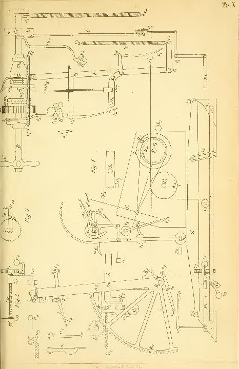
TaX
litjLL. CreiiieTidorfer.Carlsrttke


Ik.Xi
7 6'70


3 2922 00392 464 1
WBJSHT

SPECIAL COLL TS 1483 .N58Neste, K. 1865The mule spinning process
