the new ashrae/rehva active and passive beam · pdf fileactive and passive beam application...
TRANSCRIPT

Projeto Demonstrativo para o GerenciamentoIntegrado no Setor de Chillers
The New ASHRAE/REHVA Active andPassive Beam Application Design Guide
Execução Implementação Realização
Peter Simmonds– Building and Systems Analytics27/04/2016 – São Paulo

Active and PassiveBeam ApplicationDesign Guide is theresult of collaborationby worldwide experts togive system designersa current, authoritativeguide on successfullyapplying active andpassive beamtechnology.

HypothesisHypothesis• Chilled Beams are becoming more and
more popular as their efficiencyincreases and building owner’sbecome comfortable with thetechnology. With every new technologycome new challenges. Active orPassive, chilled beams are here tostay.

Learning ObjectiveLearning Objective• Define the basic design principles of
chilled beams• Demonstrate chilled beam installation
guidelines• Assess chilled beam operation using
functional testing• Examine what not to do through the
mistakes of others

Design ExperienceDesign Experience• First designs with passive beams-1983• "The Utilization and Optimization of A Buildings Thermal
Inertia in Minimizing the Overall Energy Use", ASHRAETransactions 1991 V97 Pt2.
• "The Design, Stimulation and Operation of a ComfortableIndoor Climate for a Standard Office",ASHRAE/DOE/BTEC conference, Clearwater Beach, FL1992.
• "Thermal Comfort and Optimal Energy Use", ASHRAETransactions 1993 V99 Pt1.
• "Designing Comfortable Office Climates", ASHRAE,Building Design Technology and Occupant Well-Being inTemperate Climates, Brussels, Belgium, February 1993.
• Dynamic Comfort Control", CIBSE National Conference,Manchester 1993.
• "Control Strategies for a Combined Heating and CoolingRadiant System", CIBSE National Conference, Brighton1994.

20 years ago20 years ago

Cooling Capacity ComparisonCooling Capacity Comparison
Energy• On a Mass Flow Rate Basis:-• 1 lbs of chilled water (6°Δt) transports 4x more
cooling energy than 1 lbs of air (20°Δt)
• As water weighs 800 times that of air
• On a Volume Flow Rate Basis:-• 1 FT³ of chilled water transports 1000 more
cooling energy than 1 FT³ of air (20°Δt)
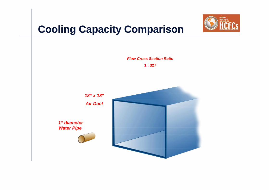
1 : 327Flow Cross Section Ratio
18“ x 18“
Air Duct
1“ diameterWater Pipe
Cooling Capacity ComparisonCooling Capacity Comparison
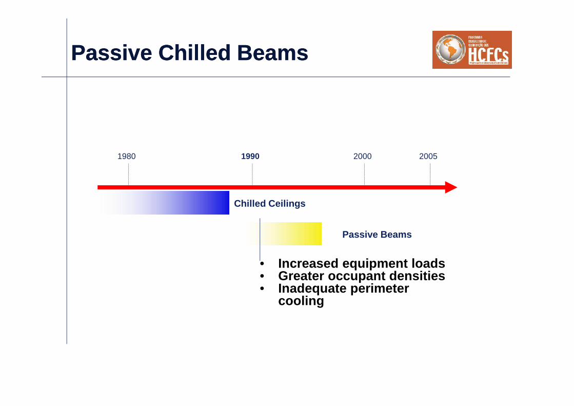
Passive Chilled BeamsPassive Chilled Beams
• Increased equipment loads• Greater occupant densities• Inadequate perimeter
cooling
1980 1990 2000 2005
Chilled Ceilings
Passive Beams

What is a Passive Chilled Beam?What is a Passive Chilled Beam?
A sensible cooling only devicethat uses chilled water abovethe room dew point toremove heat from the space

Slab
Passive BeamPassive Beam
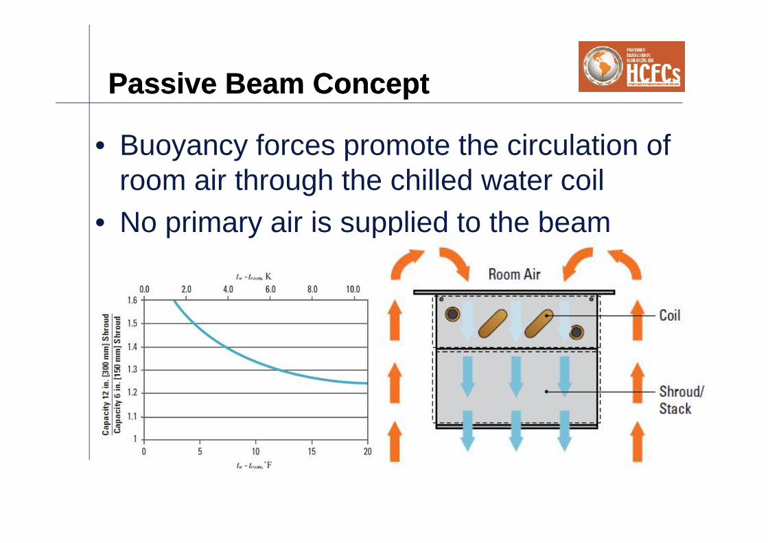
Passive Beam ConceptPassive Beam Concept
• Buoyancy forces promote the circulation ofroom air through the chilled water coil
• No primary air is supplied to the beam

Passive Beam ConceptPassive Beam Concept
Passive chilled beam forrecessed installation
Passive chilled beam forexposed installation

Passive Chilled Beam BenefitsPassive Chilled Beam Benefits
• Improved thermal comfort• Reduced energy costs• Higher cooling capacity than ceilings – 50-250
W/m• Do not require air to work, air usually introduced
at low level• Smaller ducts save space• Are not affected by relocation of partitions• Self regulating, simple on/off controls• Low noise• Low maintenance• Excellent for perimeter applications in UFAD
systems

Design ConsiderationsDesign Considerations
• Sensible cooling only– Latent gains must be controlled by air system
• Clearance required between top of coil and underside ofslab
• High free area metal perforation ceiling required– Low free area ceilings significantly reduce output– 28% free area minimum– The perforation is critical to the performance of the
beam• Can not be used to heat
– Separate heating system required• Water side pressure drop 10 kPa
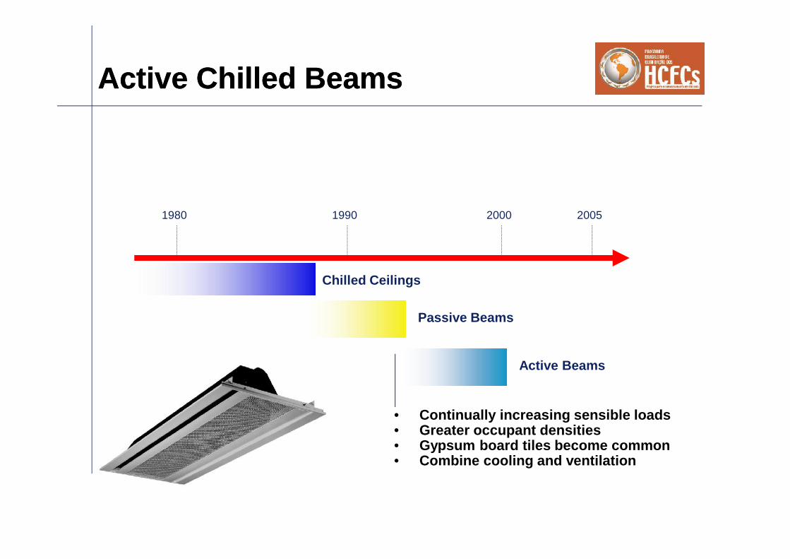
Active Chilled BeamsActive Chilled Beams
• Continually increasing sensible loads• Greater occupant densities• Gypsum board tiles become common• Combine cooling and ventilation
1980 1990 2000 2005
Chilled Ceilings
Passive Beams
Active Beams

What is an Active Chilled Beam?What is an Active Chilled Beam?
A sensible cooling only devicecombined with, a method ofintroducing primary (fresh) airto the space.
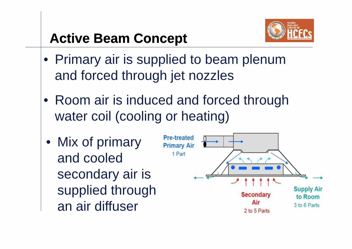
Active Beam ConceptActive Beam Concept• Primary air is supplied to beam plenum
and forced through jet nozzles
• Mix of primaryand cooledsecondary air issupplied throughan air diffuser
• Room air is induced and forced throughwater coil (cooling or heating)

Active Beam DesignsActive Beam Designs
Exposed installation
Recessed installation
Perimeter wallinstalation,under thewindow sill
•Four way;
•Hotel room;
•Under floor;
•etc.

SlabDucted Primary
air supply
Suspended
Ceiling
Active BeamActive Beam

Practical GuidelinesPractical Guidelines
• Active beams can typically handle sensible cooling capacities upto 120W/m2 of floor area. Management of higher loads (i.e. heatdriven laboratories) can be accomplished but may require amore detailed analysis
• Chilled water temperature 14-18°C• Heating water temperature between 40 and 60°C.• Inlet static pressure 50 and 250Pa.• ΔT through the coil 2 4K• Active beams are a good choice for the following applications:
– Spaces with typical heating and sensible coolingrequirements
– Buildings with moderate internal latent loads– Spaces with limited floor to ceiling heights– Spaces where low noise levels are desired

Active Beam BenefitsActive Beam Benefits• Higher cooling capacity than passive beams
– 120 W/m2• Significantly lower energy costs than VAV• Integrated cooling and ventilation• Can be used in all ceiling types• Controllable discharge pattern• Heating option• Self regulating, simple on/off controls• Low maintenance• Can be installed directly to slab
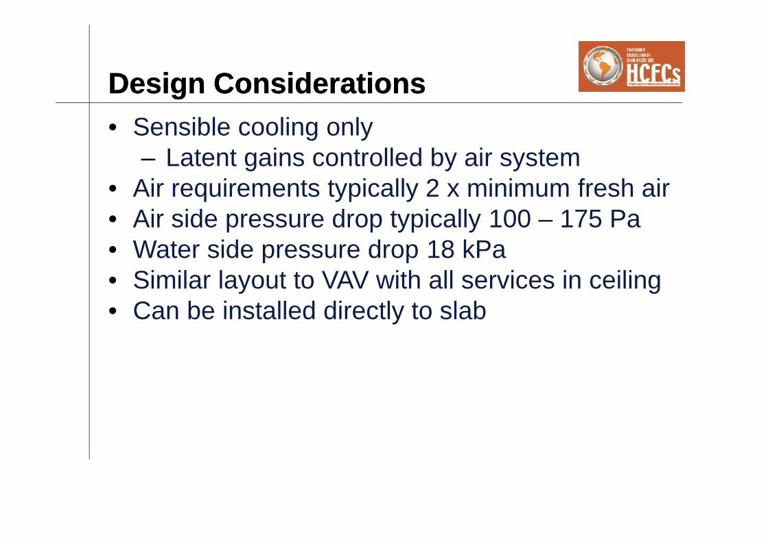
Design ConsiderationsDesign Considerations• Sensible cooling only
– Latent gains controlled by air system• Air requirements typically 2 x minimum fresh air• Air side pressure drop typically 100 – 175 Pa• Water side pressure drop 18 kPa• Similar layout to VAV with all services in ceiling• Can be installed directly to slab

Active Beam Design and SelectionProcess MethodologyActive Beam Design and SelectionProcess Methodology
• Are beams suitable for space?– E.g. High latent / sensible ratio rooms, air driven labs, kitchen
areas not suitable• Consider heating options – dictates orientation of beams
– Fin tube, chilled beams, duct reheat coils or radiant panels• Compute and schedule ventilation and latent air and room loads
– Decouple latent and sensible loads– Consider designing to 55% RH – reduces amount of latent air
required– Schedule higher of the two for min. beam air
• Choose beam orientation in room– E.g. Parallel to glazing if heating
• Select beams to maximize water cooling and minimize air delivery– Ensure recommended design velocities are achieved, use
selection software that computes velocity at wall and collisionpoints.
– Chilled beams are diffusers as well as cooling/heating devices
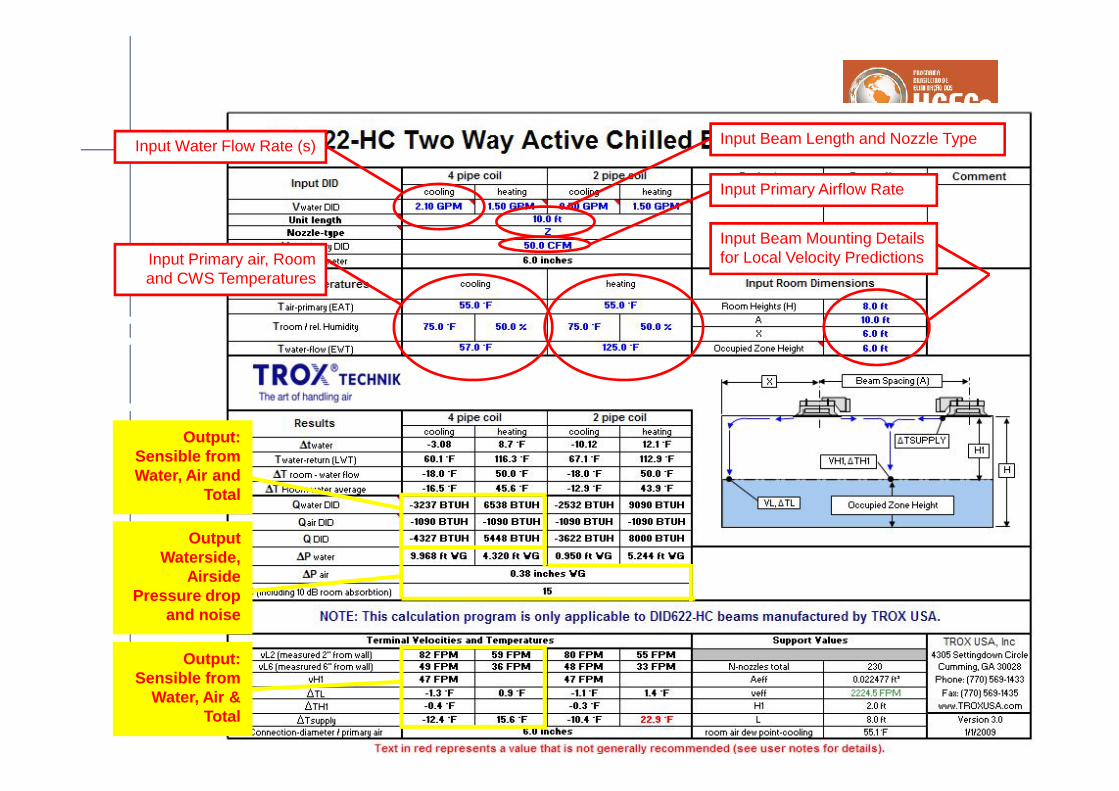
Input Beam Length and Nozzle TypeSe
lect
ion
Soft
war
e
Input Primary air, Roomand CWS Temperatures
Input Water Flow Rate (s)
Input Primary Airflow Rate
Input Beam Mounting Detailsfor Local Velocity Predictions
Output:Sensible fromWater, Air and
Total
OutputWaterside,
AirsidePressure drop
and noise
Output:Sensible from
Water, Air &Total

Simulation with CCC chilled beamsin 3DSimulation with CCC chilled beamsin 3D
8.0 m5.4 m
v1
v3
v1
v3
CBC/A-125-2400-1800Cooling 2005.10Room:Room size: 8.0 x 5.4 x 2.7 mOccupied zone: h=1.8 m / dw=0.5 mRoom air: 24.0 °C / 50 %Heat gain: 2808 WInstallation height: 2.70 mInlet water temperature: 14.0 °COutlet water temperature: 16.5 °CWater flow rate: 0.211 kg/s (4 x 0.053 kg/s)Coil capacity: 2214 W (4 x 553 W)
307 W/mWater pressure drop: 2.0 kPa
Supply air flow rate: 180 m³/h (4 x 45 m³/h)25.0 m³/(hm), 4.2 m³/(hm2)
Supply air temperature: 14.0 °CPrimary air capacity: 597 W (4 x 149 W)Total pressure drop: 121 PaTotal cooling capacity: 2811 W (4 x 703 W)
390 W/m, 65 W/m2
Dew point temperature: 12.9 °CVelocity control: side=3, middle=2Ld: -
vmax in occupied zone:vv(dt=0)T
v1~0.05 m/s~0.05 m/s-0.2 °C
v3~0.20 m/s~0.15 m/s
-0.9 °CHeat sources and their location may influence the velocity and direction of the jet
vlim = 0.20 m/s

AnalysisAnalysis
• What to look for• What to do• What not to do

Typical OfficeTypical Office

Typical OfficeTypical Office

Beam System ApplicationsBeam System Applications

Beam System ApplicationsBeam System Applications

Murphy’s Law of HVACEngineeringMurphy’s Law of HVACEngineering
•A load is a load
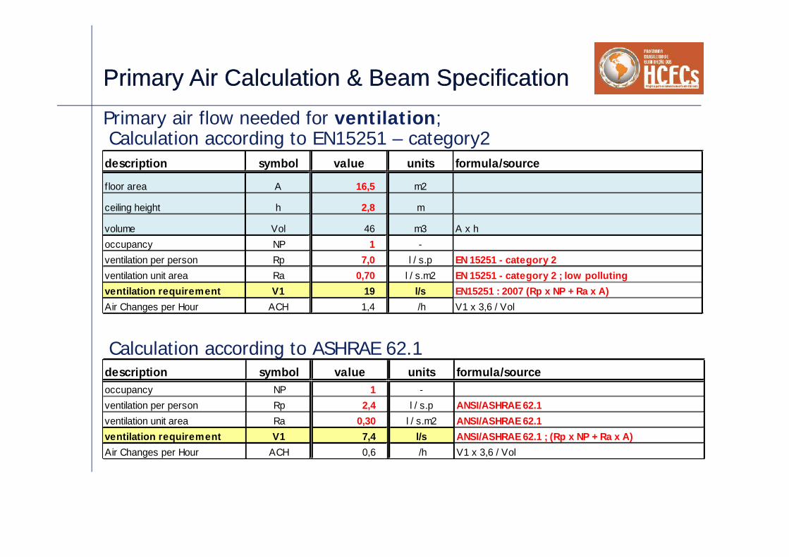
Primary Air Calculation & Beam SpecificationPrimary Air Calculation & Beam SpecificationPrimary air flow needed for ventilation;
description symbol value units formula/source
f loor area A 16,5 m2
ceiling height h 2,8 m
volume Vol 46 m3 A x hoccupancy NP 1 -ventilation per person Rp 7,0 l / s.p EN 15251 - category 2ventilation unit area Ra 0,70 l / s.m2 EN 15251 - category 2 ; low pollutingventilation requirement V1 19 l/s EN15251 : 2007 (Rp x NP + Ra x A)Air Changes per Hour ACH 1,4 /h V1 x 3,6 / Vol
Calculation according to EN15251 – category2
description symbol value units formula/sourceoccupancy NP 1 -ventilation per person Rp 2,4 l / s.p ANSI/ASHRAE 62.1ventilation unit area Ra 0,30 l / s.m2 ANSI/ASHRAE 62.1ventilation requirement V1 7,4 l/s ANSI/ASHRAE 62.1 ; (Rp x NP + Ra x A)Air Changes per Hour ACH 0,6 /h V1 x 3,6 / Vol
Calculation according to ASHRAE 62.1

Primary Air Calculation & BeamSpecificationPrimary Air Calculation & BeamSpecificationPrimary air flow needed for ventilation;
description symbol value units formula/source
f loor area A 16,5 m2
ceiling height h 2,8 m
volume Vol 46 m3 A x hoccupancy NP 1 -ventilation per person Rp 7,0 l / s.p EN 15251 - category 2ventilation unit area Ra 0,70 l / s.m2 EN 15251 - category 2 ; low pollutingventilation requirement V1 19 l/s EN15251 : 2007 (Rp x NP + Ra x A)Air Changes per Hour ACH 1,4 /h V1 x 3,6 / Vol
Calculation according to EN15251 – category2
description symbol value units formula/sourceoccupancy NP 1 -ventilation per person Rp 2,4 l / s.p ANSI/ASHRAE 62.1ventilation unit area Ra 0,30 l / s.m2 ANSI/ASHRAE 62.1ventilation requirement V1 7,4 l/s ANSI/ASHRAE 62.1 ; (Rp x NP + Ra x A)Air Changes per Hour ACH 0,6 /h V1 x 3,6 / Vol
Calculation according to ASHRAE 62.1
Very differentrequirements fromdifferent standards

Primary Air Calculation & BeamSpecificationPrimary Air Calculation & BeamSpecificationPrimary air flow needed for dehumidification;
Choice of the design indoor air dew point temperature, DPIDA;
The bigger the DPIDA the smaller the needed air flow fordehumidification.
In this example we choose, DPIDA = 16ºCdescription symbol value units formula/sourceIDA design condition cooling DBIDA 25,0 ºC Owner Projet RequirementsIDA design condition cooling DPIDA 16,0 ºC CWTin - dTIDA design condition cooling HRIDA 11,4 g/kg psychartIDA design condition cooling RHIDA 57,5 % psychart

Primary Air Calculation & BeamSpecificationPrimary Air Calculation & BeamSpecification
Primary air flow needed for dehumidification;
Choice of the design primary air dew point temperature, DPSUP;
The choice of the primary air dew point greatly affects the size of theneeded air flow for dehumidification and also the technologicalsolution of the primary air handling unit (AHU).
In this example we choose, DPSUP = 13ºC.
Since we choose a primary air dry bulb temperature of 14ºC, theprimary air supply dew point temperature can be obtained using asimple conventional AHU configuration without significant energy usefor reheat in the dehumidifying process.

Primary Air Calculation & BeamSpecificationPrimary Air Calculation & BeamSpecification
All the calculations can be organized in a spreadsheet and performed in avery productive way.The first two parts regard the outdoor air, ODA, and indoor air, IDA, designconditions.
numdescription symbol cellS units formula/source1 location - Lisbon -2 ODA design condition cooling DBODA1 32,1 ºC ASHRAE Fundamentals 1% criteria3 ODA design condition cooling MCWBODA1 19,7 ºC ASHRAE Fundamentals 1% criteria4 ODA design condition cooling HRODA1 9,3 g/kg ASHRAE Fundamentals 1% criteria5 ODA design condition dehumid DPODA2 20,0 ºC ASHRAE Fundamentals 1% criteria6 ODA design condition dehumid MCDBODA2 22,7 ºC ASHRAE Fundamentals 1% criteria7 ODA design condition dehumid HRODA2 14,8 g/kg ASHRAE Fundamentals 1% criteria8 ODA design condition heating DBODA3 5,8 ºC ASHRAE Fundamentals 1% criteria9 IDA design condition cooling DBIDA 25,0 ºC Owner Projet Requirements10 IDA design condition cooling DPIDA 16,0 ºC CWTin - dT11 IDA design condition cooling HRIDA 11,4 g/kg psychart12 IDA design condition cooling RHIDA 57,5 % psychart
OD
A d
esig
n do
nditi
onID
A d
esig
nco
nditi
ons
Note. In this spreadsheet the values in red + bold are required inputs, the values in black +normal are automatically calculated based on the input values.

Condensation preventionCondensation preventionThe occurrence of condensation on the beams isavoided by:• The supply of an adequate amount of correctly
conditioned primary air;• The implementation of an adequate chilled water
temperature control system;• At morning startup, first turn on the AHU and run
the beam CW pump only when the indoor airdew point is below the CWT setpoint.
However, condensation prevention systems arenormally applied as a safety measure.

Condensation preventionCondensation prevention
Safety condensation prevention can consist on:
• Reactive strategies,
installing condensate detectors that;• stop water supply to the beams;• Increase CWT setpoint;
• Proactive strategies ;• Window switches stopping CW flow;• Monitoring indoor air DP and resetting
CWT setpoint above the measured indoorair DP;

Primary Air Calculation & BeamSpecificationPrimary Air Calculation & BeamSpecification
Primary air flow needed for dehumidification;
The main water vapour addition to the indoor air is generated by theoccupant´s metabolism.
ṁocp

Primary Air Calculation & BeamSpecificationPrimary Air Calculation & BeamSpecification
Primary air flow needed for dehumidification;
The main water vapour addition to the indoor air is generated by theoccupant´s metabolism.
ṁocp
Degree of ActivitySensible
HeatLatentHeat
W W g/s g/hSeated at theater 70 35 0,014 50Moderately office work 75 55 0,022 79Walking, standing 75 70 0,028 101Light bench work 80 140 0,056 202Moderate dancing 90 160 0,064 230light machine work 110 185 0,074 266Heavy work 170 255 0,102 367Athletics 210 315 0,126 454
water vapourgeneration
ASHRAE Handbook of Fundamentals Calculated
Primary Air Calculation & BeamSpecificationPrimary Air Calculation & BeamSpecification
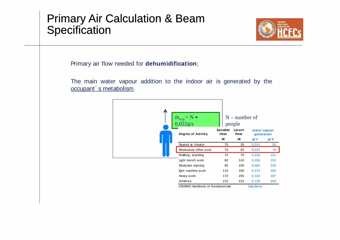
Primary air flow needed for dehumidification;
The main water vapour addition to the indoor air is generated by theoccupant´s metabolism.
ṁocp = N •0,022g/s
Degree of ActivitySensible
HeatLatentHeat
W W g/s g/hSeated at theater 70 35 0,014 50Moderately office work 75 55 0,022 79Walking, standing 75 70 0,028 101Light bench work 80 140 0,056 202Moderate dancing 90 160 0,064 230light machine work 110 185 0,074 266Heavy work 170 255 0,102 367Athletics 210 315 0,126 454
water vapourgeneration
ASHRAE Handbook of Fundamentals Calculated
N – number ofpeople

Primary Air Calculation & BeamSpecificationPrimary Air Calculation & BeamSpecification
Primary air flow needed for dehumidification;
The second water vapour addition to the indoor air results from infiltrationof outdoor air through the building envelope.
ṁocp = N •0,022g/s
qvinf
Whenever indoor pressure is lower thanoutdoor pressure, outdoor air will enterthe room through the envelope
Infiltration air entering the building shallleave the building, through the envelopeor through the HVAC system, at theindoor humidity ratio
qvinf

Primary Air Calculation & BeamSpecificationPrimary Air Calculation & BeamSpecification
Primary air flow needed for dehumidification;
The second water vapour addition to the indoor air results from infiltrationsof outdoor air through the building envelope.
ṁocp = N •0,022g/s
qvinf qvinf
ṁinf = qvinf • ρ • (HRODA – HRIDA)
qvinf (m3/s) infiltration air flow HRODA (g/Kg) outdoor air humidity ratio
ρ (Kg/m3) air density (1,2) HRIDA (g/Kg) indoor air humidity ratio

Primary Air Calculation & BeamSpecificationPrimary Air Calculation & BeamSpecification
Primary air flow needed for dehumidification;
The total water vapour addition to the indoor air is the sum of bothsources;
ṁocp = N •0,022g/s
qvinf qvinf
ṁinf = qvinf • ρ • (HRODA – HRIDA)
ṁw = ṁocp + ṁinf
Primary Air Calculation & BeamSpecificationPrimary Air Calculation & BeamSpecification
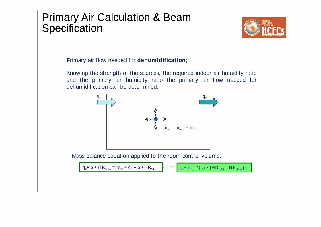
Primary air flow needed for dehumidification;
Knowing the strength of the sources, the required indoor air humidity ratioand the primary air humidity ratio the primary air flow needed fordehumidification can be determined.
ṁw = ṁocp + ṁinf
qv• ρ • HRIDA = ṁw + qv • ρ •HRSUP
qv qv
Mass balance equation applied to the room control volume;
qv= ṁw / [ ρ • (HRIDA - HRSUP) ]

Primary Air Calculation & BeamSpecificationPrimary Air Calculation & BeamSpecification
Primary air flow needed for dehumidification;
Since the dynamic load calculation software delivers the value of thedesign latent load of the space (LLAT) the strength of the water vaporsources can easily be approximated by using the following formula;
ṁw = 1.000 • LLAT / 2.500 ṁw = LLAT / 2,5
ṁw (g/s) ; mass flow of water vapour added to the spaceLLAT (W) ; latent space load (from load calculation)1.000 - ; conversion factor from Kg to g2.500 (KJ/Kg
); approximate heat content of 50% rh vapour at 24ºC less
the heat content of water at 10ºC.Note. A common design condition for the space is 50% rh at 24°C,and 10°C is normal condensate temperature from cooling anddehumidifying coils.

Primary Air Calculation & BeamSpecificationPrimary Air Calculation & BeamSpecification
Primary air flow needed for dehumidification;
Second step, calculate the strength of the water vapor sources;
ṁw = ṁocp + ṁinf
First step, choose the design indoor air and primary air humidity ratio;
Third step, calculate the needed primary air flow for dehumidification;
qv= ṁw / [ ρ • (HRIDA - HRSUP) ]
Primary Air Calculation & BeamSpecificationPrimary Air Calculation & BeamSpecification
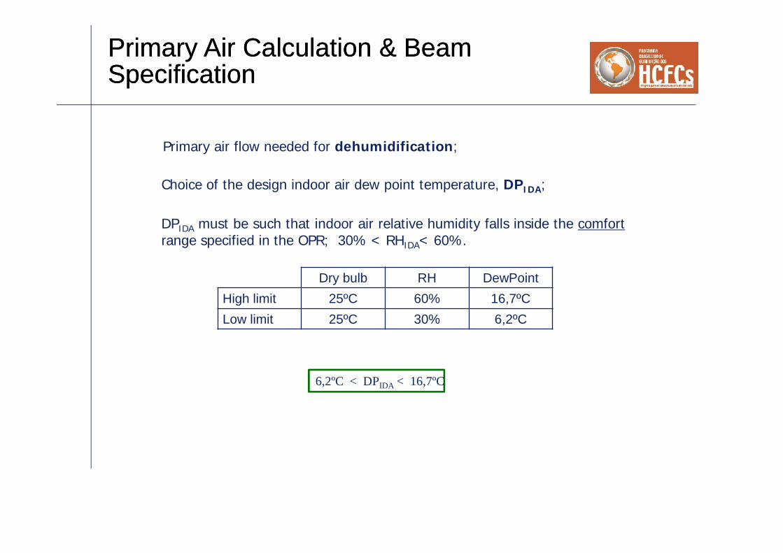
Primary air flow needed for dehumidification;
Choice of the design indoor air dew point temperature, DPIDA;
DPIDA must be such that indoor air relative humidity falls inside the comfortrange specified in the OPR; 30% < RHIDA< 60%.
Dry bulb RH DewPointHigh limit 25ºC 60% 16,7ºCLow limit 25ºC 30% 6,2ºC
6,2ºC < DPIDA < 16,7ºC
Primary Air Calculation & BeamSpecificationPrimary Air Calculation & BeamSpecification
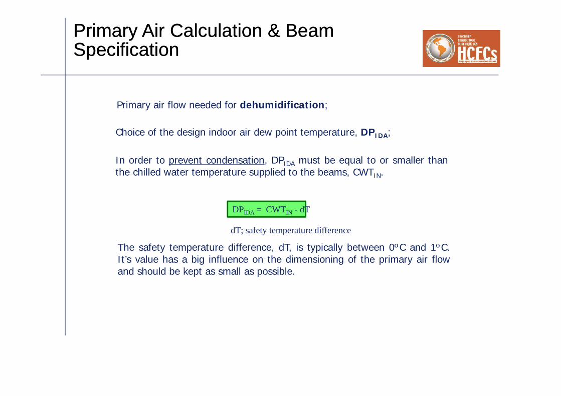
Primary air flow needed for dehumidification;
Choice of the design indoor air dew point temperature, DPIDA;
In order to prevent condensation, DPIDA must be equal to or smaller thanthe chilled water temperature supplied to the beams, CWTIN.
DPIDA = CWTIN - dT
dT; safety temperature difference
The safety temperature difference, dT, is typically between 0ºC and 1ºC.It’s value has a big influence on the dimensioning of the primary air flowand should be kept as small as possible.
Primary Air Calculation & BeamSpecificationPrimary Air Calculation & BeamSpecification
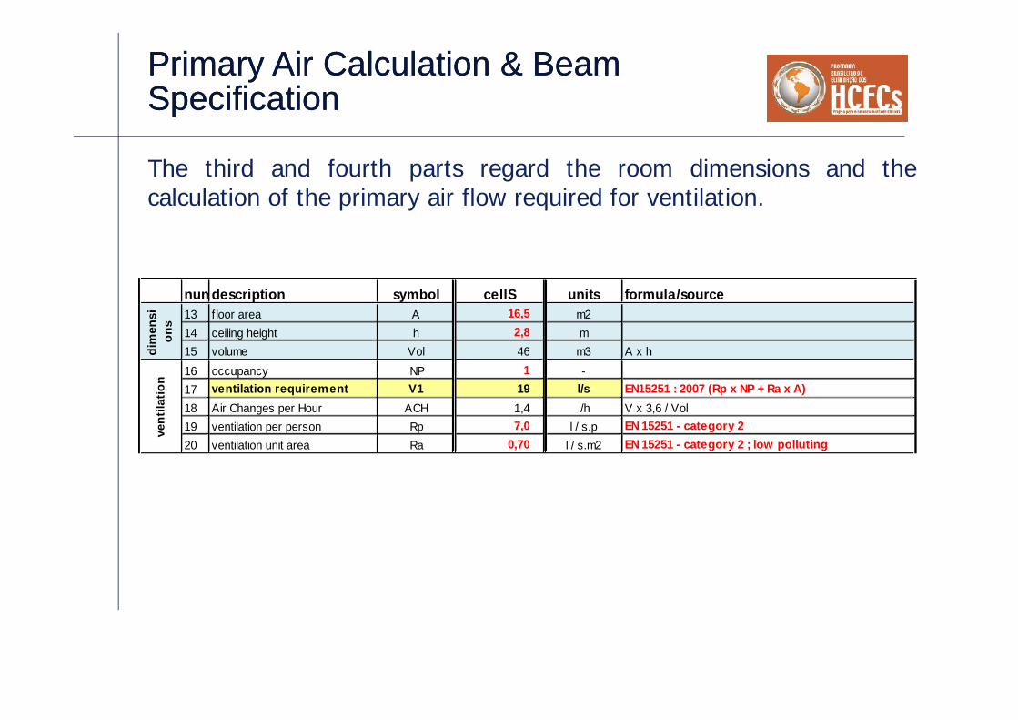
The third and fourth parts regard the room dimensions and thecalculation of the primary air flow required for ventilation.
numdescription symbol cellS units formula/source13 floor area A 16,5 m214 ceiling height h 2,8 m15 volume Vol 46 m3 A x h16 occupancy NP 1 -17 ventilation requirement V1 19 l/s EN15251 : 2007 (Rp x NP + Ra x A)18 Air Changes per Hour ACH 1,4 /h V x 3,6 / Vol19 ventilation per person Rp 7,0 l / s.p EN 15251 - category 220 ventilation unit area Ra 0,70 l / s.m2 EN 15251 - category 2 ; low polluting
dim
ensi
ons
vent
ilatio
n

Primary Air Calculation & BeamSpecificationPrimary Air Calculation & BeamSpecification
The final parts regard the calculation of the air flow needed fordehumidification and the beam selection data.
numdescription symbol cellS units formula/source21 occupant load, sens/p OCPS 75 W ASHRAE Fundamentals
22 occupant load, lat/p OCPL 55 W ASHRAE Fundamentals23 infiltration airf low INF 3,9 l/s ACHINF x Vol / 3,624 infiltration air Changes per Hour ACHINF 0,3 /h
25 sensible load (clg design cdts) LSENS 800 W from loads calcuation
26 latent load (dehumd.dsg cdts) LLAT 94 W NP x OCPL + (INF/1000) x 1,2 x 2.500 x (HRODA2 - HRIDA)
27 airflow for dehumidification V2 15 l/s 1000 x LLAT / [ 1,2 x 2500 x (HRIDA - HRSUP) ]
28 Beam chilled w ater temp. in CWTin 16,0 ºC29 Safety temperature difference dT 0,0 ºC CWTin - DPIDA
30 primary airflow V 19 l/s max (V1 ; V2)
31 primary air temperature DBSUP 14,0 ºC32 primary air dew point DPSUP 13,0 ºC psychart33 primary air relative humidity RHSUP 94 % psychart34 primary air humidity ratio HRSUP 9,4 g/kg psychart35 cooling by air (primary airf low ) Cair 245 W V x 1,2 x ( DBIDA - DBSUP )36 cooling by w ater (w ater coil) CW 555 W LSENS - Cair37 cooling by w ater (w ater coil) CW 69% % Cw / LSENS
load
sB
eam
sel
ectio
n da
taoc
cup
ancy
load
infil
trat
ion

Primary Air Calculation & BeamSpecificationPrimary Air Calculation & BeamSpecification
numdescription symbol cellS cellSE openplanN openplanNE meetingE interior1 units formula/source1 location - Lisbon Lisbon Lisbon Lisbon Lisbon Lisbon -2 ODA design condition cooling DBODA1 32,1 32,1 32,1 32,1 32,1 32,1 ºC ASHRAE Fundamentals 1% criteria3 ODA design condition cooling MCWBODA1 19,7 19,7 19,7 19,7 19,7 19,7 ºC ASHRAE Fundamentals 1% criteria4 ODA design condition cooling HRODA1 9,3 9,3 9,3 9,3 9,3 9,3 g/kg ASHRAE Fundamentals 1% criteria5 ODA design condition dehumid DPODA2 20,0 20,0 20,0 20,0 20,0 20,0 ºC ASHRAE Fundamentals 1% criteria6 ODA design condition dehumid MCDBODA2 22,7 22,7 22,7 22,7 22,7 22,7 ºC ASHRAE Fundamentals 1% criteria7 ODA design condition dehumid HRODA2 14,8 14,8 14,8 14,8 14,8 14,8 g/kg ASHRAE Fundamentals 1% criteria8 ODA design condition heating DBODA3 5,8 5,8 5,8 5,8 5,8 5,8 ºC ASHRAE Fundamentals 1% criteria9 IDA design condition cooling DBIDA 25,0 25,0 25,0 25,0 25,0 25,0 ºC Owner Projet Requirements10 IDA design condition cooling DPIDA 16,0 16,0 16,0 16,0 16,0 16,0 ºC CWTin - dT11 IDA design condition cooling HRIDA 11,4 11,4 11,4 11,4 11,4 11,4 g/kg psychart12 IDA design condition cooling RHIDA 57,5 57,5 57,5 57,5 57,5 57,5 % psychart13 floor area A 16,5 23,5 23,5 23,5 39,5 31,0 m214 ceiling height h 2,8 2,8 2,8 2,8 2,8 2,8 m15 volume Vol 46 66 66 66 111 87 m3 A x h16 occupancy NP 1 2 4 4 10 4 -17 ventilation requirement V1 19 30 44 44 98 50 l/s EN15251 : 2007 (Rp x NP + Ra x A)18 Air Changes per Hour ACH 1,4 1,7 2,4 2,4 3,2 2,1 /h V x 3,6 / Vol19 ventilation per person Rp 7,0 7,0 7,0 7,0 7,0 7,0 l / s.p EN 15251 - category 220 ventilation unit area Ra 0,70 0,70 0,70 0,70 0,70 0,70 l / s.m2 EN 15251 - category 2 ; low polluting21 occupant load, sens/p OCPS 75 75 75 75 75 75 W ASHRAE Fundamentals22 occupant load, lat/p OCPL 55 55 55 55 55 55 W ASHRAE Fundamentals23 infiltration airf low INF 3,9 5,5 5,5 5,5 9,2 0,0 l/s ACHINF x Vol / 3,624 infiltration air Changes per Hour ACHINF 0,3 0,3 0,3 0,3 0,3 0,0 /h
25 sensible load (clg design cdts) LSENS 800 1.200 1.500 1.800 3.000 1.400 W from loads calcuation
26 latent load (dehumd.dsg cdts) LLAT 94 165 275 275 643 220 W NP x OCPL + (INF/1000) x 1,2 x 2.500 x (HRODA2 - HRIDA)
27 airflow for dehumidification V2 15 27 45 45 105 36 l/s 1000 x LLAT / [ 1,2 x 2500 x (HRIDA - HRSUP) ]
28 Beam chilled w ater temp. in CWTin 16,0 16,0 16,0 16,0 16,0 16,0 ºC29 Safety temperature difference dT 0,0 0,0 0,0 0,0 0,0 0,0 ºC CWTin - DPIDA30 primary airflow V 19 30 45 45 105 50 l/s max (V1 ; V2)
31 primary air temperature DBSUP 14,0 14,0 14,0 14,0 14,0 14,0 ºC32 primary air dew point DPSUP 13,0 13,0 13,0 13,0 13,0 13,0 ºC psychart33 primary air relative humidity RHSUP 94 94 94 94 94 94 % psychart34 primary air humidity ratio HRSUP 9,4 9,4 9,4 9,4 9,4 9,4 g/kg psychart35 cooling by air (primary airf low ) Cair 245 402 593 593 1.386 656 W V x 1,2 x ( DBIDA - DBSUP )36 cooling by w ater (w ater coil) CW 555 798 907 1.207 1.614 744 W LSENS - Cair37 cooling by w ater (w ater coil) CW 69% 67% 60% 67% 54% 53% % Cw / LSENS
OD
A d
esig
n do
nditi
onB
eam
sel
ectio
n da
taID
A d
esig
nco
nditi
ons
dim
ensi
ons
vent
ilatio
noc
cupa
nc y
infil
trat
ion
load
s
Primary Air Calculation & BeamSpecificationPrimary Air Calculation & BeamSpecification
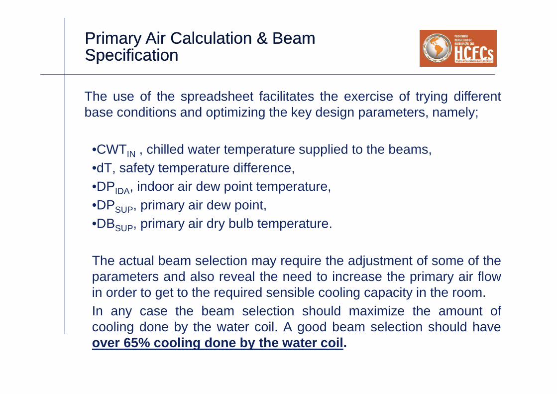
The use of the spreadsheet facilitates the exercise of trying differentbase conditions and optimizing the key design parameters, namely;
•CWTIN , chilled water temperature supplied to the beams,•dT, safety temperature difference,•DPIDA, indoor air dew point temperature,•DPSUP, primary air dew point,•DBSUP, primary air dry bulb temperature.
The actual beam selection may require the adjustment of some of theparameters and also reveal the need to increase the primary air flowin order to get to the required sensible cooling capacity in the room.In any case the beam selection should maximize the amount ofcooling done by the water coil. A good beam selection should haveover 65% cooling done by the water coil.

ControllabilityControllability
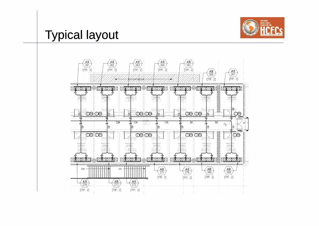
Typical layoutTypical layout

ControlsControls

Our preliminary design practice,standardization.Our preliminary design practice,standardization.
• Obtain space sensible cooling loads from Trace• Calculate the latent gain from people• Calculate the space humidity conditions from the
supply air humidity ratio and the latent gain, plotthis on a psychrometric chart
• Select a unit that meets your design criteria (usemanufacturers tools if necessary)

Dew Point ControlDew Point Control
10 15 20 25
30
35
40
45
50
55
55
60
60
ENTHALPY - BTU PER POUND OF DRY AIR
15
20
25
30
35
40
45
50
ENTHALPY - B
TU PER POUND OF D
RY AIR
SATURATION TEMPERATURE - °
F
35 40 45 50 55 60 65 70 75 80 85 90 95 100
105
110
115
120
DR
Y B
ULB
TEM
PER
ATU
RE
- °F
.002
.004
.006
.008
.010
.012
.014
.016
.018
.020
.022
.024
.026
.028
10% RELATIVE HUMIDITY
20%
30%
40%
50%
60%
70%
80%
90%
35
3540
4045
45 50
50 55
55 60
6065
6570
70
75
75
80
80
85 WET BULB TEMPERATURE - °F
85
90
12.5
13.0
13.5
14.0 VOLUM
E- CU.FT. PER LB. DRY AIR
14.5
15.0
HU
MID
ITY
RAT
IO -
POU
ND
S M
OIS
TUR
E PE
R P
OU
ND
DR
Y AI
R
supply air temperature
space conditiondew point
panel surface temp panel surface temp
R R
ASHRAE PSYCHROMETRIC CHART NO.1NORMAL TEMPERATURE
BAROMETRIC PRESSURE: 29.921 INCHES OF MERCURYCopyright 1992
AMERICAN SOCIETY OF HEATING, REFRIGERATING AND AIR-CONDITIONING ENGINEERS, INC.
SEA LEVEL
0
1.0 1.0
-
2.04.08.0
-8.0-4.0-2.0-1.0
-0.5-0.4-0.3-0.2-0.1
0.1
0.2
0.3
0.4
0.5
0.6
0.8-2000
-1000
0
500
1000
1500
2000
3000
5000
-
SENSIBLE HEAT QsTOTAL HEAT Qt
ENTHALPYHUMIDITY RATIO
hW

ObservationsObservations
• Active Beams are not the solution to the worldsenergy problems.
• Active Beam applications need to be engineered• Fundamental psychometrics and design
knowledge are essential• Active beams should not be used to try and keep
up with the others

Where do the Energy Savings comefrom?Where do the Energy Savings comefrom?
• A load is a load• The kW’s have to go somewhere• Suggest modeling an active beam system as a
four pipe fan coil system, with outside air volumesdetermined from separate calculations and fanpower determined from separate calculations
• The possible chilled water advantage

Energy analysisEnergy analysis• Use of water to transport thermal energy;
description symbol
coolingwith
water
coolingwith air units formula/source
density ρ 1.000 1,2 kg/m3specific heat cp 4,2 1,0 kJ/kg.Kdelta T ΔT 2 10 K current valuecooling per (l/s) cap 8,4 0,012 kW ρ . cp . ΔT / 1000flow per kW cooling q 0,12 83,33 l/s 1 / capfan/pump pressure P 200 1,5 kPa current valuefan/pump efficiency (global) η 0,55 0,55 - current valuefan/pump powerper kW cooling E 43 227 W / kWclg q . P / η
Air requires around 5 timesmore energy to supply thesame cooling capacity
Adds 23% to thesensible cooling load
Energy used to supply 1.000W cooling

New YorkNew YorkAnnual Electric Energy by End Use
Annual Source Energy Annual Site Energy Lighting HVAC Energy Peak
total EUI Electric Nat Gas Electric Electric Nat Gas total Electric Cooling
Annual Energy Use (kWh) Mbtu kBtu/sf/yr kWh Therms kWh kWh Therms Mbtu kW tons
0 Base Design - VAV 29,992 167 2,594,809 34,236 599,160 711,876 8,412 3,271 1,025 456
1 0+Fan Coils 31,795 177 2,814,940 29,727 599,160 932,006 3,924 3,573 1,031 513
2 0+Radiant Ceiling 27,349 152 2,336,119 34,295 599,160 453,185 8,482 2,395 862 426
3 0+Active Beams 27,564 153 2,356,092 34,400 599,160 473,158 8,585 2,473 873 461
Incremental Savings
1 0+Fan Coils -1,803 -10.02 -220,131 4,509 0 -220,130 4,488 -302 (-9%) -6 (-1%) -57 (-13%)
2 0+Radiant Ceiling 2,643 14.75 258,690 -59 0 258,691 -70 876 (27%) 163 (16%) 30 (7%)
3 0+Active Beams 2,428 13.56 238,717 -164 0 238,718 -173 797 (24%) 152 (15%) -5 (-1%)
Cumulative Savings
1 0+Fan Coils -1,803 -10.02 -220,131 4,509 0 -220,130 4,488 -302 (-9%) -6 (1%) -57 (-13%)
2 0+Radiant Ceiling 2,643 14.75 258,690 -59 0 258,691 -70 876 (27%) 163 (-16%) 30 (7%)
3 0+Active Beams 2,428 13.56 238,717 -164 0 238,718 -173 797 (24%) 152 (-15%) -5 (-1%)

Los AngelesLos Angeles
Los AngelesAnnual Electric Energy by End Use
Annual Source Energy Annual Site Energy Lighting HVAC Energy Peak
total EUI Electric Nat Gas Electric Electric Nat Gas total Electric Cooling
Annual Energy Use (kWh) Mbtu kBtu/sf/yr kWh Therms kWh kWh Therms Mbtu kW tons
0 Base Design - VAV 29,779 165 2,679,658 23,422 599,160 796,725 124 2,732 938 391
1 0+Fan Coils 31,813 177 2,879,748 23,276 599,160 996,816 7 3,403 948 389
2 0+Radiant Ceiling 26,668 148 2,376,977 23,301 599,160 494,044 35 1,690 795 330
3 0+Active Beams 26,824 149 2,392,191 23,309 599,160 509,257 37 1,742 818 346
Incremental Savings1 0+Fan Coils -2,034 -11.3 -200,090 146 0 -200,091 117 -671 -10 1 (0%)
2 0+Radiant Ceiling 3,111 17.35 302,681 120 0 302,682 89 1,042 144 61 (16%)
3 0+Active Beams 2,955 16.48 287,468 112 0 287,468 87 990 120 44 (11%)
Cumulative Savings1 0+Fan Coils -2,034 -11.3 -200,090 146 0 -200,091 117 -671 -10 1 (0%)
2 0+Radiant Ceiling 3,111 17.35 302,681 120 0 302,682 89 1,042 144 61 (16%)
3 0+Active Beams 2,955 16.48 287,468 112 0 287,468 87 990 120 44 (11%)

Cost ExperienceCost Experience
• Are active beam systemscompetitive with VAV or otheralternatives?

ShortcomingsShortcomings
• Overcooling

ApplicationsApplications
• No Beams in meeting rooms• Calculate latent space loads• Determine fresh air supply

Last slideLast slide
• It is up to the Engineer ofrecord as to what systemis used


Execução Implementação Realização