the open civil engineering journal · the open civil engineering journal, 2017, 11, ... the lateral...
TRANSCRIPT
Send Orders for Reprints to [email protected]
The Open Civil Engineering Journal, 2017, 11, (Suppl-1, M4) 345-357 345
1874-1495/17 2017 Bentham Open
The Open Civil Engineering Journal
Content list available at: www.benthamopen.com/TOCIEJ/
DOI: 10.2174/1874149501711010345
RESEARCH ARTICLE
Behavior of Steel Welded Tapered Beam-column
A.I. Dogariu*, A. Crișan, M. Cristuțiu, D.L. Nunes and A. Juca
Steel Structures and Structural Mechanics department, Politehnica University of Timisoara, Timisoara, Romania
Received: November 17, 2015 Revised: May 02, 2016 Accepted: June 23, 2016
Abstract: Steel structural elements with variable cross-section, made of welded plates, are largely used in the construction industryfor both beams and columns in accordance with the stress and stiffness demand in the structure. These types of elements are mainlyused for the design of single storey frames with pitched roof rafters and pinned column base. Rafters and columns can be designed astapered members made of steel welded plates, respecting the bending moment diagrams for gravitational load combination. Thispaper deals with experimental tests performed on tapered beam-columns elements, subjected to both bending moment andcompressive axial force together with analytical investigation.
Keywords: Boundary conditions, Eurocode interaction formulas, Experimental investigation, General method, Lateral-torsionalbuckling, Tapered beam-column members.
1. INTRODUCTION
For steel industrial building, the application of elements with web-tapered I cross-section, made of welded thinplates, is a common practice. Such low rise structure elements are generally designed from gravitational loadcombinations. Rafters and columns shape respects the bending moment diagrams for gravitational load combinationreducing the material consumption and lowering the structural self-weight. So, in case of an earthquake, low inertiaforces will be provided for single span industrial buildings. This fact makes that the seismic design concept not toimpose a high structural ductility class. Within the framework of an RFCS research program a simple chart basedprocedure to select the best seismic design concept for portal frames have been proposed [1]. Depending on the framegeometry one may propose a low-dissipative or dissipative concept. The method mentioned above indicates the fact thatfor most cases of portal frames with variable column and beam cross-sections, the optimal choice will be a low-dissipative concept. This concept eliminates the strict anti-seismic conditions referring to cross-section class, elementsslenderness, imposed detailing conditions, etc. and conduct to a more effective cost of the building.
Due to the tapered shape of the element and from efficiency reasons, high cross-section class of web wall, i.e. 3(elastic) and 4 (slender) may be obtained at the end with the maximum height. The buckling capacity of such a slendermember will be determined by the restraining elements efficiency and position, end support conditions and initialgeometrical and material imperfections.
At class 3 cross-sections members, used generally for columns elements, restrained against lateral or/and torsionalbuckling, the coupling between sectional capacity and overall elastic buckling of the members in compression and/or inbending may occur. In case of class 4 (slender) section members, found at the rafter highest section of the tapered web,the sectional buckling (e.g. local buckling of the walls or distortion) could appear in elastic domain.
For member which are not laterally restrained, or the restrains are not effective, the global failure mode of themembers will be characterized by the lateral torsional mode, either alone or in interaction with local buckling.
* Address correspondence to this author at Steel Structures and Structural Mechanics department, Universitatea Politehnica din Timisoara str. IoanCurea 1, 300224, Timisoara, Romania; Tel: +40 (0) 256 403 922; Fax: +40 (0) 256 403 917; E-mails: [email protected], [email protected]

346 The Open Civil Engineering Journal, 2017, Volume 11 Dogariu et al.
Nowadays, European design codes do not provide directly a practical design approach of this kind of widespreadstructure.
Because pitch roof portal frame rafters are subject to axial compressive loads, the problem of buckling behavior ismore complex compared with the beams of multi-storey frames. Covering large volume spaces, the lateral torsionalbuckling capacity of the members is reduced if no restrains, or efficient restrains, are provided.
Structural stability criteria are the most important design aspect of steel buildings. The European codes series EN1993 for design of steel structures, gives analytical and numerical procedures for buckling check. The norm provisionsare generally referring at single, isolated component elements, but also gives some hints regarding the entire structuresbuckling capacity determination. Most code provisions cover only regular geometric shapes, simple load cases andregular boundary conditions. In case of random shapes, complicated loading cases (complex shape of internal forcesdiagrams) and support conditions, numerical analyses are recommended. The EN 1993 allows the use of finite elementsoftware based investigation of complex structures by using the general method. Apart from real members’ behavior(influenced by material plastic behavior, real lateral bending, torsion and warping stiffness, and second order effects,etc.), this procedure gives the possibility to take into account almost all factors concerning the buckling behavior suchas geometric and material imperfections, residual stresses, actual boundary conditions.
It is obvious for all designers that the actual European norms are more detailed and complex than the previousnational ones. Most of the criticism related to European norms are precisely those things. In spite of this fact, manyaspects, such as elastic critical loads formulas, are left out of the current version. In the scientific literature andtextbook, one may find these analytical formulas, but these are also limited to prismatic members with doublysymmetric cross-section and precise loading and boundary conditions.
Using the provisions of the general method one could attempt to design the tapered members and complexstructures, but the application of this method involves advanced structural analysis (e.g. linear buckling analysis,nonlinear analysis, etc.) and skillful and well-trained engineers.
The interaction formulas for the strength and buckling check of individual elements for different type of load (e.g.tension, compression, bending, shear, torsion, and combination between them) are provided only for uniform members.Many investigations have performed on the behavior uniform elements subjected to bending moment and axial force[2 - 4]. Nevertheless information regarding the behavior of tapered elements is still limited.
This paper presents the results of an experimental study carried out at the Politehnica University of Timisoara, in theCEMSIG Laboratory on single tapered member subjected to bending moment and axial force. The aim of the paper is tounderstand the real behavior of the web tapered beam-columns member and different members and cross-sectionalwalls slenderness.
2. EXPERIMENTAL INVESTIGATION
The experimental specimen was isolated from a real pitched-roof portal frame designed according to the codeprovision and following the philosophy for single storey industrial building. Due to the testing frame geometriclimitation and actuator capacity, a small-span portal frame was chosen, having 12 m span, 4 m height and roof angle ofα=8 as shown in Fig. (1).
Fig. (1). Reference frame [5].
Following a low-dissipative design concept, the load hypothesis was taken according to EN1991 provisions. For the
4m
12m

Behavior of Steel Welded Tapered Beam-column The Open Civil Engineering Journal, 2017, Volume 11 347
tributary area computation, a usual 6 m bay was considered. The most severe load combination for the structural designof the frame members was 1.35 P (permanent loads) + 1.5 S (snow loads), for the ultimate limit state and 1.0 P+1.0 Sfor the serviceability limit state, where dead load of roof cladding is P=0.35 kN/m2 and snow load is S=1.6 kN/m2. Thestructural elements were fabricated from S355 steel grade. The analysis method and design formulas respect the currentEN 1993-1-1 provisions.
Generally, at the base the frames are pinned, if the tapered column is rationally used, using a single base plate withfour bolts inside the flanges of the column. Portal frames are realized with moment resisting connections; therefore therafter-column connection becomes rigid.
2.1. Experimental Specimens
Experimental tests were performed on steel welded columns. For different behavior cases, a number of six columncross-section geometries were used in order to model different slenderness of the column web and flanges. Theirgeometric dimensions and connection details are presented in Fig. (2). The overall height of the cross-sections andthickness of flanges have remained unchanged for all the experimental sets.
Fig. (2). Specimen typology (dimensions are in mm) [5].
The first set of columns has a 6 mm web thickness and the second one an 8 mm web thickness, both sets are madeof S355 structural steel, with flanges width of 200 mm, 180 mm and 160mm. The geometric dimensions of thespecimens are presented in Table 1. Considering the building envelope disposal, the outer flange is kept vertical, whilstthe inner one is inclined to give the tapered shape. At the top of the column a rigid joint was considered, thus a 20 mmthick extended end plate was provided accordingly and at the base pinned connection a 15 mm flush end plate. In orderto avoid the bolt failure, 16 M20 gr. 12.9 bolts on 8 rows were used for the upper fixed connection and 4 M20 grade 8.8on 2 rows in the case of the holding down bolts from the base connection.
Table 1. Geometric dimension of specimens and cross-section properties.
Specimen L [mm] h1 [mm] h2 [mm] b tf tw
C1_8 3376 250 600 200 10 8C2_6 3376 250 600 200 10 6C3_8 3376 250 600 160 10 8C4_6 3376 250 600 160 10 6C5_8 3376 250 600 180 10 8C6_6 3376 250 600 180 10 6
2.2. Material Properties
The nominal yield strength of steel plates considered for the column specimen was fy = 355 N/mm2. In order todetermine the real mechanical properties of the material, tensile tests were performed on three coupons extracted fromthe each plate thickness used for the fabrication of the test specimens (Fig. 3).
The tensile test was carried out with UTS RSA 250kN - universal test machine. The results are presented in Table 2only for webs and flanges material. For each specimen is indicated the resulted yield strength (fy) and ultimate yieldstrength (fu). The stress-strain curves prove the normal steel behavior, i.e. an elastic behavior untill yielding, followedby a small yielding plateau, a strain hardening part until necking of the specimen at the ultimate tensile strength.Although the nominal value was 355 N/mm2 (MPa), the experimental measures indicated significant differences varying
A- AA
A
bb
w
t =20 mm
p
p
B - B
1
h 2
t =10mm
t =15 mm
h 1
h 2
f
t =10mmf
t =6...8mm
3393
20 3376 15
5040
h
B
B

348 The Open Civil Engineering Journal, 2017, Volume 11 Dogariu et al.
the thickness of plates. The different values for the yield limit, especially for flanges may have a significant influenceon the member capacity.
Fig. (3). Tested coupons after tensile test (6, 8, 20, 15, 10 mm, starting from bottom left counterclockwise) [5].
Table 2. Real material mechanical properties.
SpecimenWeb Flanges
fy tw [MPa] fu tw [MPa] fy tf [MPa] fu tf [MPa]C1_8 410 518 267 401C2_6 319 493 267 401C3_8 347 502 379 577C4_6 388 500 379 577C5_8 347 502 379 577C6_6 388 500 379 577
2.3. Test Setup and Instrumentation
The testing setup is based on a very simple static scheme. The aim of this scheme is to replicate the real loadingcondition on a portal frame column, i.e. members subjected to bending moment and axial force (Fig. 4). Theexperimental specimen, put in a horizontal position, is pinned connected at the bottom end and is rigidly connected to avery stiff and strong loading element. The additional vertical cantilever loading element has a mobile pin near thetesting element and is loaded at the opposite free end with a concentrated load, introduced by a hydraulic actuator. Also,this element is lateral restrained at the top in order to avoid out-of-plane displacement due to inherent imperfections.These restrains aim at preventing the rotation of the loading element around his own axis. This fact will avoid therotation of the specimen around his weak axis. The distance between the loading application point and the specimencentroid, i.e. the load eccentricity, represent the ratio between the value of the bending moment and axial force. Havingthe same length, at each new experimental test, only the column specimen was replaced.
Fig. (4). Testing setup and loading scheme (bending moment diagram) [5].
The bottom simple support was designed in such a way to allow horizontal displacement and to prevent verticaldisplacement both upwards and downwards. For the bending moment to be transferred directly from the vertical columnto the tested specimen, it was very important for the mobile pin to work properly. For this particular reason, a roller

Behavior of Steel Welded Tapered Beam-column The Open Civil Engineering Journal, 2017, Volume 11 349
system was provided (Fig. 5). Besides allowing free horizontal displacement, the simple support prevented theappearance of a horizontal reaction force that would lead to the change of the bending moment diagram. The testedcolumn was considered fixed at the left end and pinned at the right end. The fixed end was made through an extendedend plate bolted connection with high strength steel M20 bolts grade 12.9, while the pinned end is made through a flushend connection, with high strength steel bolts M20 grade 8.8.
Fig. (5). Boundary conditions for the test setup: a) – simple support –roller; b) pinned column base; c) rigid column connection [5].
The load was applied quasi-statically through a 1000 kN capacity Quiri hydraulic jack, in displacement controlprocedure with a displacement velocity of 3.33 mm/min. Overall view of the test setup is presented in Fig. (6). The in-plane and out-of-plane displacements were monitored during tests through a number of 18 Novotechnic displacementtransducers (Fig. 4). Some of them measuring the absolute displacement of the indicated points related to pointsindependent from the testing frame (e.g: D1,D3…D9), whilst some of the relative displacement between points locatedon the tested frame (e.g: D2f,b).
a) b) c)
Fig. (6). Testing setup and specimen position [5].
350 The Open Civil Engineering Journal, 2017, Volume 11 Dogariu et al.
3. EXPERIMENTAL RESULTS
The results obtained from the experimental investigation will be summarized in the form of tables and graphs. Theresults recorded during the tests, in terms of load (F) and displacements (d) were converted in terms of bending moment(M) and rotation (ϕ) and finally the (M-ϕ) curve was built.
The bending moment at the top of the column (left side of the specimen) was computed using Eq. (1) whilst therotation of the specimen at the front of the vertical element was computed using Eq. (2):
(1)
Where: Mred,EX is the reduced bending moment at the column top; F is the applied horizontal force; Lr is the leverarm of the applied force, distance between point of applied force and the intersection of neutral axis of vertical columnand of tapered column (Lr = 1.85m); Lcn is the nominal length of the column (3.6 m); Lca is the actual length of thecolumn (Lca = 3.41m) (Fig. 4).
(2)
Where: ϕ is the rotation of the specimen with respect to its initial position; D1 is the measured displacement; Lr is thelever arm of the applied force (Lr = 1.85m).
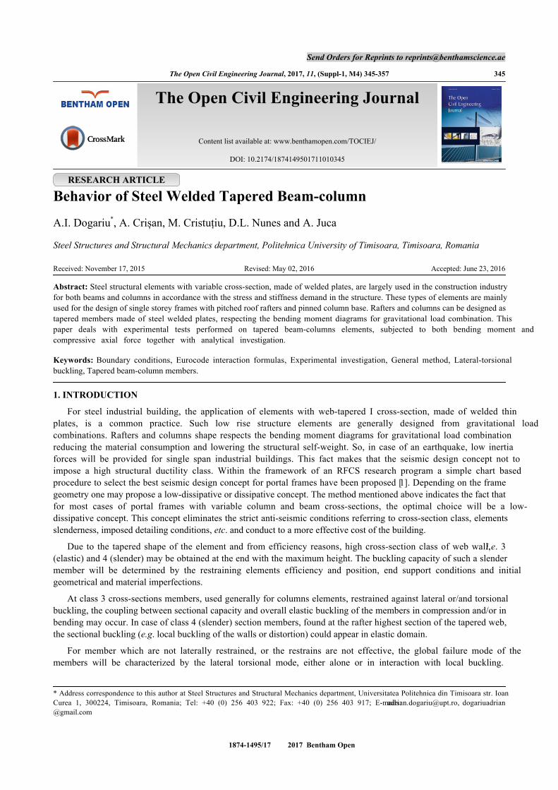
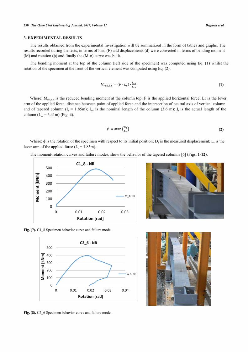
The moment-rotation curves and failure modes, show the behavior of the tapered columns [6] (Figs. 1-12).
Fig. (7). C1_8 Specimen behavior curve and failure mode.
Fig. (8). C2_6 Specimen behavior curve and failure mode.
𝑀𝑟𝑒𝑑,𝐸𝑋 = (𝐹 ∙ 𝐿𝑟) ∙𝐿𝑐𝑎
𝐿𝑐𝑛
∅ = atan (D1
Lr)
0
100
200
300
400
500
0 0.01 0.02 0.03
Mo
me
nt
[kN
m]
Rotation [rad]
C1_8 - NR
C1_8 - NR
0
100
200
300
400
500
0 0.01 0.02 0.03 0.04
Mo
me
nt
[kN
m]
Rotation [rad]
C2_6 - NR
C2_6 - NR
Behavior of Steel Welded Tapered Beam-column The Open Civil Engineering Journal, 2017, Volume 11 351
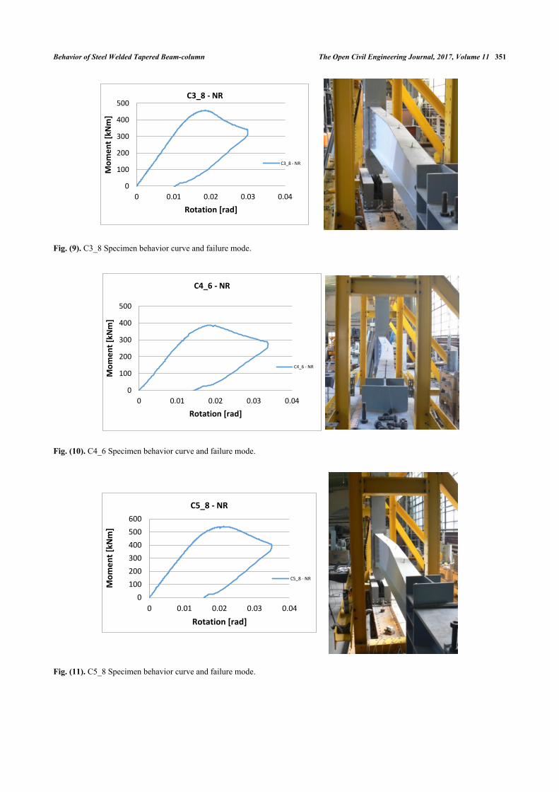
Fig. (9). C3_8 Specimen behavior curve and failure mode.
Fig. (10). C4_6 Specimen behavior curve and failure mode.
Fig. (11). C5_8 Specimen behavior curve and failure mode.
0
100
200
300
400
500
0 0.01 0.02 0.03 0.04
Mo
me
nt
[kN
m]
Rotation [rad]
C3_8 - NR
C3_8 - NR
0
100
200
300
400
500
0 0.01 0.02 0.03 0.04
Mo
me
nt
[kN
m]
Rotation [rad]
C4_6 - NR
C4_6 - NR
0
100
200
300
400
500
600
0 0.01 0.02 0.03 0.04
Mo
me
nt
[kN
m]
Rotation [rad]
C5_8 - NR
C5_8 - NR
352 The Open Civil Engineering Journal, 2017, Volume 11 Dogariu et al.
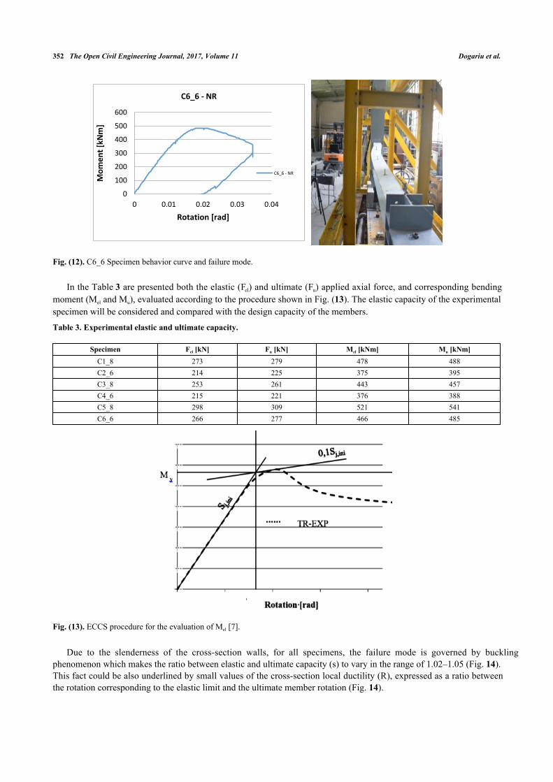
Fig. (12). C6_6 Specimen behavior curve and failure mode.
In the Table 3 are presented both the elastic (Fel) and ultimate (Fu) applied axial force, and corresponding bendingmoment (Mel and Mu), evaluated according to the procedure shown in Fig. (13). The elastic capacity of the experimentalspecimen will be considered and compared with the design capacity of the members.
Table 3. Experimental elastic and ultimate capacity.
Specimen Fel [kN] Fu [kN] Mel [kNm] Mu [kNm]C1_8 273 279 478 488C2_6 214 225 375 395C3_8 253 261 443 457C4_6 215 221 376 388C5_8 298 309 521 541C6_6 266 277 466 485
Fig. (13). ECCS procedure for the evaluation of Mel [7].
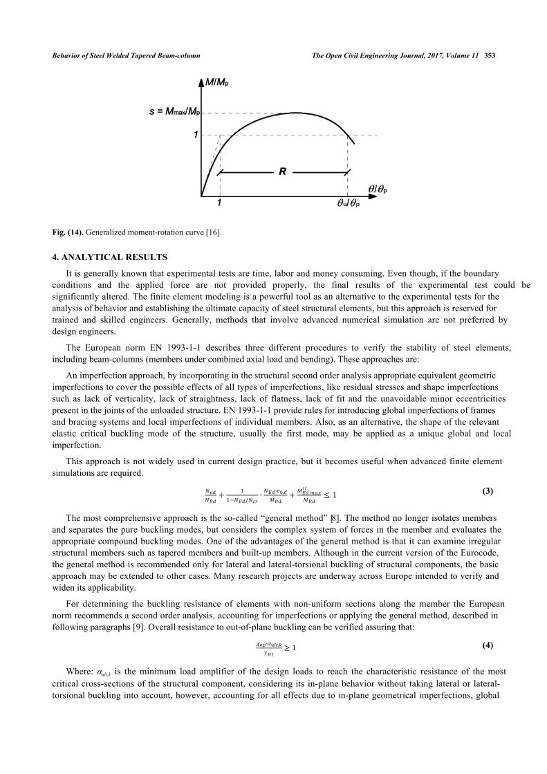
Due to the slenderness of the cross-section walls, for all specimens, the failure mode is governed by bucklingphenomenon which makes the ratio between elastic and ultimate capacity (s) to vary in the range of 1.02–1.05 (Fig. 14).This fact could be also underlined by small values of the cross-section local ductility (R), expressed as a ratio betweenthe rotation corresponding to the elastic limit and the ultimate member rotation (Fig. 14).
0
100
200
300
400
500
600
0 0.01 0.02 0.03 0.04
Mo
me
nt
[kN
m]
Rotation [rad]
C6_6 - NR
C6_6 - NR
Behavior of Steel Welded Tapered Beam-column The Open Civil Engineering Journal, 2017, Volume 11 353
Fig. (14). Generalized moment-rotation curve [16].
4. ANALYTICAL RESULTS
It is generally known that experimental tests are time, labor and money consuming. Even though, if the boundaryconditions and the applied force are not provided properly, the final results of the experimental test could besignificantly altered. The finite element modeling is a powerful tool as an alternative to the experimental tests for theanalysis of behavior and establishing the ultimate capacity of steel structural elements, but this approach is reserved fortrained and skilled engineers. Generally, methods that involve advanced numerical simulation are not preferred bydesign engineers.
The European norm EN 1993-1-1 describes three different procedures to verify the stability of steel elements,including beam-columns (members under combined axial load and bending). These approaches are:
An imperfection approach, by incorporating in the structural second order analysis appropriate equivalent geometricimperfections to cover the possible effects of all types of imperfections, like residual stresses and shape imperfectionssuch as lack of verticality, lack of straightness, lack of flatness, lack of fit and the unavoidable minor eccentricitiespresent in the joints of the unloaded structure. EN 1993-1-1 provide rules for introducing global imperfections of framesand bracing systems and local imperfections of individual members. Also, as an alternative, the shape of the relevantelastic critical buckling mode of the structure, usually the first mode, may be applied as a unique global and localimperfection.
This approach is not widely used in current design practice, but it becomes useful when advanced finite elementsimulations are required.
(3)
The most comprehensive approach is the so-called “general method” [8]. The method no longer isolates membersand separates the pure buckling modes, but considers the complex system of forces in the member and evaluates theappropriate compound buckling modes. One of the advantages of the general method is that it can examine irregularstructural members such as tapered members and built-up members. Although in the current version of the Eurocode,the general method is recommended only for lateral and lateral-torsional buckling of structural components, the basicapproach may be extended to other cases. Many research projects are underway across Europe intended to verify andwiden its applicability.
For determining the buckling resistance of elements with non-uniform sections along the member the Europeannorm recommends a second order analysis, accounting for imperfections or applying the general method, described infollowing paragraphs [9]. Overall resistance to out-of-plane buckling can be verified assuring that:
(4)
Where: αult.k is the minimum load amplifier of the design loads to reach the characteristic resistance of the mostcritical cross-sections of the structural component, considering its in-plane behavior without taking lateral or lateral-torsional buckling into account, however, accounting for all effects due to in-plane geometrical imperfections, global
𝑁𝑒𝑑
𝑁𝑅𝑑+
1
1−𝑁𝐸𝑑/𝑁𝑐𝑟∙
𝑁𝐸𝑑∙𝑒0,𝑑
𝑀𝑅𝑑+
𝑀𝐸𝑑 𝑚𝑎𝑥𝐼𝐼
𝑀𝑅𝑑≤ 1
𝜒𝑜𝑝∙𝛼𝑢𝑙𝑡,𝑘
𝛾𝑀1≥ 1

354 The Open Civil Engineering Journal, 2017, Volume 11 Dogariu et al.
and local, where relevant;
αcr,op is the minimum load amplifier for the in-plane design loads to reach the elastic critical resistance of thestructural component with regard to lateral or lateral torsional buckling without accounting for in-plane flexuralbuckling.
χop is the reduction factor for non-dimensional slenderness to take account of lateral and lateral-torsionalbuckling. The reduction factor χ may be determined from either of the following methods: the minimum (therecommended option) or an interpolated value between the values χ and χLT.
As one can notice, the general method involves advanced numerical tools and stability knowledge being verydifficult to use in case of practical design application [10].
The last procedure deals with isolated members and is the conventional engineering solution for buckling problems,but its explicit code provisions are limited to uniform members with simple support and loading conditions. Thismethod makes two simplifications considering the member isolated from the structure applying boundary conditions(supports, restraints or loads) and the buckling of the member is determinate separately for the pure buckling modes (i.e.flexural buckling for pure compression and lateral-torsional buckling for pure bending) and combined by applyinginteraction factors. The article will follow an analytical design procedure dealing with the stability of non-prismaticmembers [11]. The obtained analytic results will be compared with the experimental ones. The method is based onsimple interaction formulas (see Eq. 5-7).
(5)
(6)
(7)
In the Table 4 the main steps to assess the member buckling capacity in case of beam-columns are presented.
Table 4. Design steps for isolated member approach.
Step In the most stressed section Isolated member
1 Calculate the design values of the compressive force and bending moment on the memberNEd
My,Rd
2 Calculate the compression and bending resistances of the cross section according with the cross section classNc,Rk
Mc,Rk
3Calculate the pure elastic critical compressive force according to minor axis flexural buckling Ncr and the pure elastic
critical bending moment of the member Mcr
Ncr
Mcr
4 Calculate the member slenderness and reduction factors separately for pure minor axis flexural buckling and pure lateral-torsional buckling (λ, χ, λLT and χLT)
5 Calculate the interaction factors connecting the two pure buckling cases (Annex A or Annex B) kzy
6 Calculate the design buckling resistance of the member and check the member combination of axial load and bending
The elastic critical moment for lateral torsional buckling Mcr was computed, according to the method described in[11] considering an equivalent height of the element, and it was also confirmed by finite element simulations [12], i.e.buckling analysis on individual isolated members. Generally, for critical moment computation, the wrapping of thesection (kw) and also the end rotation on plan (kz) are considered free. In general, this default consideration can conductat significant underestimation of the members’ capacity. Making a more accurate estimation, according to [13] for thistype of end connection (Fig. 15), both degrees of freedom can be restrained, leading to a safety factor of the elementcloser to the one obtained by experimental tests.
op
𝑁𝐸𝑑
𝜒∙𝑁𝑅𝑑+ 𝜇 ∙
1
1−𝑁𝐸𝑑𝑁𝑐𝑟
∙𝐶𝑚∙𝑀𝐸𝑑
𝑀𝑅𝑑≤ 1 𝜇 =
1−𝑁𝐸𝑑/𝑁𝑐𝑟
1−𝜒∙𝑁𝐸𝑑/𝑁𝑐𝑟
𝑁𝐸𝑑
𝜒𝑦∙𝑁𝑅𝑘/𝛾𝑀1+ 𝑘𝑦𝑦 ∙
𝑀𝑦,𝐸𝑑+Δ𝑀𝑦,𝐸𝑑
𝜒𝐿𝑇∙𝑀𝑦,𝑅𝑘/𝛾𝑀1+ 𝑘𝑦𝑧 ∙
𝑀𝑧,𝐸𝑑+Δ𝑀𝑧,𝐸𝑑
𝑀𝑧,𝑅𝑘/𝛾𝑀1≤ 1.0
𝑁𝐸𝑑
𝜒𝑧∙𝑁𝑅𝑘/𝛾𝑀1+ 𝑘𝑧𝑦 ∙
𝑀𝑦,𝐸𝑑+Δ𝑀𝑦,𝐸𝑑
𝜒𝐿𝑇∙𝑀𝑦,𝑅𝑘/𝛾𝑀1+ 𝑘𝑧𝑧 ∙
𝑀𝑧,𝐸𝑑+Δ𝑀𝑧,𝐸𝑑
𝑀𝑧,𝑅𝑘/𝛾𝑀1≤ 1.0
𝜆𝑧 = √𝑁𝑐,𝑅𝑘
𝑁𝑐𝑟
𝛼→ 𝜒𝑧
𝜆𝐿𝑇 = √𝑀𝑐,𝑅𝑘
𝑀𝑐𝑟
𝛼→ 𝜒𝐿𝑇
𝑁𝐸𝑑
𝑁𝑏,𝑅𝑑+ 𝑘𝑧𝑦 ∙
𝑀𝑦,𝐸𝑑
𝑀𝑏,𝑅𝑑

Behavior of Steel Welded Tapered Beam-column The Open Civil Engineering Journal, 2017, Volume 11 355
Fig. (15). Extended end plate connection (kz = kw = 0.5) [13].
To determine the real utilization ratio of the elements, the real mechanical properties have been considered, togetherwith the nominal value of the yielding limit. Also, a comparison between the different effective length factors kz and kw
that depend on the support condition was done. The results are presented in Table 5. The design values for NEd and MEd
introduced in the interaction formula verification are the capacities determined experimentally. The resulting ratio is, infact, the underestimation ratio of the analytical calculation related to the trustful experimental results.
Table 5. Analytical results.
End support condition kz=kw=0.5 kz=kw=1Material properties Determined Nominal
Specimen Ratio*C1_8 1.13 1.38 1.54C2_6 0.94 1.15 1.28C3_8 1.36 1.29 2.04C4_6 1.24 1.18 1.85C5_8 1.38 1.31 1.97C6_6 1.32 1.25 1.87
* the ratio between the experimental and analytical capacity
Despite using more appropriate end-condition, leading to closer values for members’ capacity, the analyticalprediction gives up to 38% higher values. These differences could be explained by the members’ overstrength due to theamount of strain-hardening, defined as the non-dimensional measure of the ultimate capacity of steel members.Empirical formulation, described and discussed by means of artificial neural network formulation, predicting therotation capacity (R) and the flexural overstrength (s) could be found in the literature [14 - 16].
Using a wide database of experimental results, D’Aniello et al. [14] proposed an empirical equation to predict theflexural overstrength factor (see Eq. 8). In our case, involving class 3-4 cross-sections, the overstrength factor takesvalues around 0.76 similar with the buckling reduction factors.
(8)
Where;
(9)
(10)
Are the flange and the web slenderness parameters, respectively, with bf being the flange width, tf the flangethickness, dw,e the compressed part of the web, and tw the web thickness; Lv being the shear length, i.e., the distancebetween the plastic hinge and the point of zero bending moment.
1
𝑠= 1.71 + 0.167𝜆𝑓
2 + 0.006𝜆𝑤2 − 0.134
𝑏𝑓
𝐿𝑣− 0.007
𝐸
𝐸ℎ− 0.239
𝜀ℎ
𝜀𝑦
𝜆𝑓 =𝑏𝑓
2 𝑡𝑓√
𝑓𝑦
𝐸
𝜆𝑤 =𝑑𝑤,𝑒
𝑡𝑤√
𝑓𝑦
𝐸
356 The Open Civil Engineering Journal, 2017, Volume 11 Dogariu et al.
CONCLUSION
Following the results showed in Table 5 one may notice an important difference between the analytical results andexperimental ones in case of free end support condition, i.e. kz=kw=1. Even if these are the default values recommendedbeing used in practical design, a careful analysis of the connection details could lead to a more rational design. Thescatter in the material properties could lead to a non-conservative situation. For example, in case of C1_8 and C2_6, theflanges were manufactured using an inferior steel grade, probably S275, a situation in which a limit design process willoverestimate the real element capacity.
Even if the use of restrained end condition for warping and rotation about weak axis z (kz=kw=0.5), has proven togive more accurate results, in case of inconsistencies, which often appear in practice, some situation may lead to unsafedesign.
ETHICS APPROVAL AND CONSENT TO PARTICIPATE
Not applicable.
HUMAN AND ANIMAL RIGHTS
No Animals/Humans were used for studies that are base of this research.
CONSENT FOR PUBLICATION
Not applicable.
CONFLICT OF INTEREST
The authors confirm that this article content has no conflict of interest.
ACKNOWLEDGEMENTS
This work was partially supported by the strategic grant POSDRU/159/1.5/S/137070 (2014) of the Ministry ofNational Education, Romania, co-financed by the European Social Fund – Investing in People, within the SectoralOperational Programme Human Resources Development 2007-2013.
The authors gratefully acknowledge the financial support of “National University Research Council – NURC-CNCSIS-Romania” through the national research grant PN-II-RU-TE-2010-1/38.
REFERENCES
[1] P. Hradil, M. Mielonen, and L. Fülöp, "Optimization tools for steel portal frames – Optimization results", Research report VTT-R-00567-11,2011.
[2] A. Taras, and R. Greiner, "Development of consistent buckling curves for torsional and lateral-torsional buckling", Steel Construction, vol. 1,no. 1, pp. 42-50, 2008.[http://dx.doi.org/10.1002/stco.200890005]
[3] J. Szalai, and F. Papp, "On the probabilistic evaluation of the stability resistance of steel columns and beams", J. Constr. Steel. Res., vol. 65,no. 3, pp. 569-577, 2009.[http://dx.doi.org/10.1016/j.jcsr.2008.08.006]
[4] B. Farshi, and F. Kooshesh, "Buckling Analysis of structural steel frames with inelastic effects according to codes", J. Constr. Steel. Res., vol.65, no. 2009, pp. 2078-2085, 2009.
[5] M. Cristuțiu, D. Nunes, and A. Dogariu, "Experimental study on laterally restrained steel columns with variable I cross sections", Int. J. SteelCompos. Struct., vol. 13, no. 3, 2012.
[6] D. L. Nunes, and I. M. Cristuțiu, "Experimental study on the behavior of tapered web elements under compression and bending moment",Mathmatical Modelling in Civil Engineering, vol. 14, pp. 158-167, 2012.
[7] M. Cristuțiu, and D. Nunes, "Influence of the cross section slenderness on the buckling behavior of steel welded tapered beam-column", In:The 5th International Conference on Structural Engineering, Mechanics and Computation (SEMC 2013), CRC Press: Cape Town, 2013.
[8] J. Szalai, "The General Method of EN 1993-1-1", New Steel Constructions, 2011.
[9] F. Papp, and J. Szalai, "New approaches in Eurocode 3 – efficient global structural design. Part 0: An explanatory introduction", In:Terästiedote (Finnish Steel Bulletin), 5, Helsinki, 2010.
[10] S. da Silva, L. Rebelo, and Marques L., "Application of the general method for the evaluation of the stability resistance of non-uniformmembers", In: Proceedings of the Sixth International Conference on Advances in Steel Structures - ICASS 09 , 2009
Behavior of Steel Welded Tapered Beam-column The Open Civil Engineering Journal, 2017, Volume 11 357
[11] L. S. da Silva, R. Simoes, and H. Gervasio, Design of steel structures, Eurocode 3: Design of steel structures Part 1-1: General Rules andrules for buildings., ECCS Eurocode Design Manuals, 2010.
[12] M. Cristuțiu, D. Nunes, and A. Dogariu, "Steel members with variable I cross sections under bending and compression with lateral restraints-behavior by experimental test", In: Design Fabrication and Economy of Metal Structures, 2013, pp. 193-198.
[13] D. Dubină, V. Ungureanu, R. Zaharia, A. Dogariu, A. Crișan, I. Țuca, and C. Neagu, "The stability of steel elements according to SR EN1993-1.1 - Design recommendations, comments and examples of application", In: Buletinul Construcțiilor.
[14] M. D’Aniello, R. Landolfo, V. Piluso, and G. Rizzano, "Ultimate behaviour of steel beams under non-uniform bending", J. Constr. Steel. Res.,vol. 78, pp. 144-158, 2012.[http://dx.doi.org/10.1016/j.jcsr.2012.07.003]
[15] E. M. Güneyisi, M. D'Aniello, R. Landolfo, and K. Mermerdaş, "A novel formulation of the flexural overstrength factor for steel beams", J.Constr.Steel Res., vol. 90, pp. 60-71, 2013.[http://dx.doi.org/10.1016/j.jcsr.2013.07.022]
[16] E. M. Güneyisi, M. D'Aniello, R. Landolfo, and K. Mermerdaş, "Prediction of the flexural overstrength factor for steel beams using artificialneural network. Steel and Composite Structures", Steel. Compos. Struct., Int. J., vol. 17, no. 3, pp. 215-236, 2014.
© 2017 Dogariu et al.
This is an open access article distributed under the terms of the Creative Commons Attribution 4.0 International Public License (CC-BY 4.0), acopy of which is available at: https://creativecommons.org/licenses/by/4.0/legalcode. This license permits unrestricted use, distribution, andreproduction in any medium, provided the original author and source are credited.