the open mechanical engineering journal, open access ... · design criteria for high power engines...
TRANSCRIPT

Send Orders for Reprints to [email protected]
The Open Mechanical Engineering Journal, 2015, 9, 271-281 271
1874-155X/15 2015 Bentham Open
Open Access
Design Criteria for High Power Engines Crankshafts S. Baragetti*,1,2
1GITT - Centre on Innovation Management and Technology Transfer, Università degli Studi di Bergamo, Via Salvecchio 19, Bergamo 24129, Italy 2Department of Management, Information and Production Engineering, Università degli Studi di Bergamo, viale Marconi 5, Dalmine 24044, Italy
Abstract: The reliability of any mechanical system, in which the linear displacement of a piston is converted into the rotation of a power transmission shaft, strongly depends on the reliability of the crankshaft. The crankshaft is the critical component and any damage occurring to the crankshaft may put the mechanical system out of order. The numerical finite element simulation of crankshafts with multiple rods is often time consuming even if quite accurate if the aim is to evaluate the stress-strain behavior at the notched area and verify the component. The development of a simplified numerical model would prove effective to reduce the time needed to reach a good approximation design of the crankshaft. The aim of this paper is to give the designer a numerical procedure that allows to determine the strain and stress state and verify crankshafts having two or more rods.
Keywords: Crankshaft, fatigue resistance, FEM models, machine design, reliability, stress concentration.
1. INTRODUCTION
Notwithstanding the combustion engine is a consolidated mechanical system due to its continuous developments during the decades, its components are still subject of research in terms of strength to mass ratio enhancement, acoustic, dynamic and vibration behavior, stress and fatigue assessment. The mechanical components that have a great impact on the reliability and performances of the engine are the transmission gears, the crankshaft, the connecting rod with its piston pin. Such components may lead to engine failure in case of low reliability. The design of a new crankshaft, or the upgrade of a crankshaft to higher power engines, is always a big challenge for the designer [1, 2]. The component has to be carefully analysed and verified just because a failure occurring to the crankshaft would put out of order all the mechanical system [3, 4]. The crankshaft is put in series to all the other components of the engine in the fault crankshaft analysis and the reliability of the whole system heavily depends on the reliability of the crankshaft. The crankshaft is a geometrically relatively complex component which is often obtained by machining a forged piece of steel or cast iron. Mechanical, thermo-mechanical or thermo-chemical surface treatments, such as shot peening, rolling, nitriding or case-hardening allow to increase the surface hardness and induce beneficial compressive residual stresses at the surface that prevent crack nucleation and propagation [5-9]. In the last few years recent researches helped the designer in applying
*Address correspondence to this author at the GITT - Centre on Innovation Management and Technology Transfer, Università degli Studi di Bergamo, Via Salvecchio 19, Bergamo 24129, Italy; Tel: +39-035-2052382; Fax: +39-035-2052043; E-mail: [email protected]
really newly developed surface treatments [10-15] and coatings that allow to generate a favorable residual stress state and increase the surface hardness. Thin hard coatings deposited by means of PVD, CVD and PECVD technologies are, for the time being, wider and wider utilized in an increasing number of structural applications and may represent a powerful tool to enhance the fatigue behavior of crankshafts [16-19]. It is well known that the final fatigue resistance of a crankshaft is not only dependent on the geometry and mechanical characteristics of the material, but is strongly influenced by the load history too, the induced stress state and residual stress state due to surface treatments or thin hard coatings, by the surface hardness and a lot of technological factors. The problem of high power engines crankshafts’ design is treated in many literature references. Some other references dealing with the design of components connected to the crankshaft prove effective in giving good procedures for the crankshaft’s design. The dynamic behavior of a crankshaft for an in-line 4-cylinder, 4-strokes, internal combustion turbocharged direct injection gasoline engine was studied in [20]. The Authors developed a numerical multi-body model by using commercial codes. The crankshaft and cylinder block were considered as flexible bodies and the results of the study are the first eight natural frequencies. This study allows to assess the vibro-acoustic behavior of the engine. The fatigue resistance behavior of the crankshaft was not taken into consideration in this paper and the model does not take into consideration the effect of clearance at the joints. Joints are assumed to be ideal without clearance. In [21] Z.-F. Bai, B.-j. Yang, Y. Sun, Investigation on Dynamics of Mechanical System with Clearance Joint, The Open Mechanical Engineering Journal, 2014, 8, 224-229, the effects of clearance joints for

272 The Open Mechanical Engineering Journal, 2015, Volume 9 S. Baragetti
mechanical system are investigated numerically, with particular attention to dynamic responses and vibration characteristics. The response is nonlinear and the study gives useful guidelines to improve the reliability of the response of a mechanisms caused by joint clearance. Even in this paper the fatigue assessment of the components of the mechanical system is not developed. In [22] B. Zheng, Y. Liu, R. Liu, Stress and Fatigue of Connecting Rod in Light Vehicle Engine, The Open Mechanical Engineering Journal, 2013, 7, 14-17, the connecting rod of light vehicle engines was modelled by using a commercial FEM code. The Authors mapped the stress and strain field of the connecting rod and increased the safety factor in order to increase the reliability. In [23] S. Baragetti, S. Mori, E. Scarabotto, “A Study on Connecting Rods for IC Engines”, International Journal of Computer Applications in Technology, Inderscience Enterprises Ltd, Genève, Switzerland, Vol. 26, No.3, pp. 126-136, 2006, the connecting rod stress behaviour and its response towards buckling were deepened. A FEM commercial code was used to the stress and strain assessment while mathematical models allows to optimize the bucking behaviour. The attention is focused on the piston pin used in a large medium-speed gas engine in [24]. The design of the component was optimized in order to enhance the engine dynamics and global performances. A FEM model was developed by using a commercial code and a structural optimization was performed. The mathematical optimization procedure allowed to find the best values of the effective length of the piston pin and the inner diameter of the piston pin. The literature offers several methods that allow to design a crankshaft and other important components of the engine connecting with the crankshaft. Some of these methods are quite useful if the aim of the designer is to have a very simple and fast first approximation design of the crankshaft [25, 26]. In such simple theoretical methods the crankshaft is divided into as many pieces as the number of rods and each piece is simply supported. This is a quite useful assumption that allows to have a quick response but in many cases is not enough to assure the resistance of the component. On the other hand the finite element method enables the designer to develop quite accurate numerical models in which all kind of loads, boundary conditions, pre-stress, residual stresses and surface treatment effects of any kind can be simulated [27-29]. Nevertheless such analyses are often time consuming and expensive and requite a good level of knowledge of the numerical approach and analysis of the results. The aim of this paper is to provide the machine designer with a numerical model that would prove to be much more effective than the simple approximate ones and at the same time would not be as time consuming and expensive as the numerical based ones, would allow to reach a good design level for the crankshaft. Such a design level may be enough in many engineering applications in which the need is to evaluate the strain-stress state and verify the fatigue resistance of the component.
2. THE CRANKSHAFT
The crankshaft is one of the key components of an internal combustion engine and is therefore studied with particular attention. It is also one of the most critical because
it is subject to high loads, cyclically variable in modulus and direction. The crankshaft has a complex geometry and its dimensions vary according to the type of application. It is often called crankshaft or, less frequently, "goose-neck" and is used for the transformation of the rectilinear motion of the piston into a rotary motion. The crankshaft is fitted with a series of pins of coaxial bench that lean, by the interposition of bearings, on suitable supports in the crankcase. In order to function properly, the bearings need a continuous and adequate flow of oil that realizes the minimum thickness of the meatus necessary for the sustenance of the pin and avoid contact between the mating surfaces. The bearings are oil supplied directly from the lubrication circuit, while those of the connecting rod receive the oil by suitable channels, drilled in the crankshaft, which connect the crankshaft with those of the connecting rod (Figs. 1, 2) [30]. The crank pins, coupled to the connecting rods by the interposition of bushings, are connected to the pins of the counter through the crank arms (shoulders or cheeks). To prevent significant vibration during operation of the engine, the crankshaft must be properly balanced [1-4] by means of counterweights on the crank arms on the side opposite to the crankpin. The arrangement of the crank pins is related to the number of cylinders and the architecture of the engine [1-4]. In the area of connection between the shaft pins and the cheeks it is necessary to reduce the stress concentration by means of adequate rolled radii. The function of the fittings is to avoid scratches and overheating caused by mechanical working (turning, grinding and grinding) of the shoulder and of the pins, as well as to improve the stress gradient and reduce the notch effect which would cause the premature fatigue rupture of the component. The flywheel is fixed at one end of the shaft, while on the other end the viscous damper and pulley control of the subsidiary bodies are mounted. The elements connected to the crankshaft are shown in Fig. (3). The crankshaft of the present work is mounted on a diesel engine with maximum power of 110 kW and is currently being made in ductile iron (GS 700) or heat-treated steel (42CrMo4 UNI-EN 10083). The main static mechanical properties of the materials are reported in Table 1. The crankshaft is currently mounted on a six-cylinder in-line, having the characteristics listed in Table 2 [30].
3. ASSESSMENT OF THE STATE OF STRESS OF THE CRANKSHAFT
The assessment of the structural behavior and state of stress of the crankshaft requires the evaluation of the dynamic vibrations. The classical approach to the study of the stresses of the crankshaft aims to transform the real system (the crankshaft) into an equivalent system with concentrated parameters. The "discretized" model, compared to a simplification in the calculation phase, however, poses some limitation on the accuracy of the results. The model does not take into account the interaction between the torsional modes, bending and axial loads, but evaluates their contribution separately giving result of their composition. In addition, this model does not consider the presence of oil at the journals bearing and connecting rod [30-34]. Crankcase, connecting rod, piston, flywheel and auxiliaries have not been modeled, and their presence is taken into account in a

Design Criteria for High Power Engines Crankshafts The Open Mechanical Engineering Journal, 2015, Volume 9 273
similar way to what was done by the classical lumped mass method. The mass of the connecting rod is divided into a rotating component and a translating alternating component which contributes, together with the piston and the pressure of the gases, to determine the force that is discharged onto the shaft. To take into account the other components, the inertia equivalent to the masses actually connected to the shaft (alternator, distribution, water pump) are added to the crankshaft. Moreover, the classical methods of calculation, currently used, need to take into account experimental diagrams that enable to modify the nominal stresses in the areas of stress concentration or were steep stress gradients are present. In order to enable a more accurate evaluation of the stress state at junctions, and the determination of the stress concentration factor, a three-dimensional finite element model of the shaft is needed. In order to proceed with the design of the crankshaft it is necessary to simulate in the numerical FEM model the correct restraints at the ends of the mechanical component. The application of restraints and loads in an approximate way, however, is acceptable because the critical zone, ie the connecting channel is sufficiently far away from the areas of application of constraints and loads. These considerations are useful for the development of the numerical model of the crankshaft. The crankshaft is also considered to be subject to a fixed constraint, or rather subject to small displacements, while the
vectors of the loads rotate with respect of the crankshaft. This is done to reduce the computational time. The analysis is not a substitute to the dynamic analysis of the component but is, for the moment, a good approximation and can eliminate the uncertainties introduced by the complex geometry of the crankshaft.
Fig. (2). Lubrication channels of the crankshaft.
Fig. (1). Crankshaft for a six-cylinder high power engine.
Table 1. Main static mechanical properties of the materials of the crankshaft (for cast iron of casting tube part and to the steel after cleaning).
Material UNI/DIN Mechanical Properties
E [MPa] ν G [MPa] ρ [kg/dm3] Rm [MPa] Rp0,2 min [MPa] A% Hardness
GS 700 172600 0.226 70392 7.30 740 470 2 240÷290 HB
42CrMo4 206000 0.3 79231 7.83 900÷1100 >550 >12 270÷330 HB
Fig. (3). Main elements of the motor crankshaft.

274 The Open Mechanical Engineering Journal, 2015, Volume 9 S. Baragetti
Table 2. Main characteristics of the six-cylinder engine.
Termodynamic cycle 4-stroke diesel
N° of cylinder and disposition 6 online
Bore x Stroke [mm] 105 x 115,5
Engine capacity [cm3] 6000
Speed controller electronic
Supercharger Turbo/Intercooler
Cooling liquid/oil
Constant max. power [kW/cv] 110/150
Constant power max range [g/min] 2000-2350
Constant max. torque [Nm] 625
Constant torque max range [g/min] 1400-1600
Distribution 3 valves per cylinder
Weight of the vehicle [kg] 6100
3.1. Finite Element Model of the Crankshaft
The need for more rigorous and in-depth structural analyses leads to the development of finite element numerical models. The finite element method (FEM) is one of the most effective computational tools currently in use in structural mechanics, able to perform the discretization of the continuous system. The available 3D finite elements are the solid brick and tetrahedra elements. The components of the displacement and force vector of the solid brick element are 24 while for the tethraedra element are 12 (clearly shown in Fig. (4)) [35].
(1)
Fig. 4. 3D finite elements: a) solid eight nodes linear brick, b) nodal displacements for the solid eight nodes linear brick, c) nodal forces for the solid eight nodes linear brick, d) tethraedra four nodes linear brick. The components of the displacement and force vector of the solid brick element are 24 while for the tethraedra element are 12 (clearly shown in Figure 4) [35]. The linear shape functions of the brick linear elements are reported in equation 2). Equation 3) reports the vector of the linear displacements for each node. 24 independent coefficients are needed to write equation 2), from α1 to α24. The shape functions allow to establish a relationship between the nodal displacements and the displacements of any point located inside the finite element.
a) b)
c)
d)
c)
(1)
(2)
(3)
(a) (b)
(c) (d)
Fig. (4). 3D finite elements: (a) solid eight nodes linear brick, (b) nodal displacements for the solid eight nodes linear brick, (c) nodal forces for the solid eight nodes linear brick, (d) tethraedra four nodes linear 3D elements.
Design Criteria for High Power Engines Crankshafts The Open Mechanical Engineering Journal, 2015, Volume 9 275
The linear shape functions of the brick linear elements are reported in equation 2). Equation 3) reports the vector of the linear displacements for each node. 24 independent coefficients are needed to write equations 2), from α1 to α24. The shape functions allow to establish a relationship between the nodal displacements and the displacements of any point located inside the finite element. 𝑢 = 𝛼1 + 𝛼2𝑥 + 𝛼3𝑦 + 𝛼4𝑧 + 𝛼5𝑥𝑦 + 𝛼6𝑥𝑧 + 𝛼7𝑦𝑧 + 𝛼8𝑥𝑦𝑧 𝑣 = 𝛼9 + 𝛼10𝑥 + 𝛼11𝑦 + 𝛼12𝑧 + 𝛼13𝑥𝑦 + 𝛼14𝑥𝑧 + 𝛼15𝑦𝑧 + 𝛼16𝑥𝑦𝑧 (2) 𝑤 = 𝛼17 + 𝛼18𝑥 + 𝛼19𝑦 + 𝛼20𝑧 + 𝛼21𝑥𝑦 + 𝛼22𝑥𝑧 + 𝛼23𝑦𝑧 + 𝛼24𝑥𝑦𝑧
𝛿! = 𝑢! 𝑥, 𝑦, 𝑧 , 𝑣! 𝑥, 𝑦, 𝑧 , 𝑤! 𝑥, 𝑦, 𝑧!
(3)
It is possible to modify equation 2) into equation 4) that links the displacememts to the modified shape functions N1, N2 and N3:
𝑢 𝑥, 𝑦, 𝑧 = 𝑁! 𝑥, 𝑦, 𝑧 𝑓
𝑓 = 𝑓! , 𝑓! , 𝑓! , 𝑓! , 𝑓! , 𝑓! , 𝑓! , 𝑓!!
(4)
𝑢 𝑥, 𝑦, 𝑧𝑣 𝑥, 𝑦, 𝑧𝑤 𝑥, 𝑦, 𝑧
=𝑁! 𝑥, 𝑦, 𝑧𝑁! 𝑥, 𝑦, 𝑧𝑁! 𝑥, 𝑦, 𝑧
𝑓
From the displacement 2) it is possible to obtain deformations (equations 5 and 6).
𝜀! =!"!"
𝜀! =!"!"
𝜀! =!"!"
𝛾!" =!"!"+ !"
!"
𝛾!" =!"!"+ !"
!"
𝛾!" =!"!"+ !"
!"
(5)
𝜀! =! !!!"
!{𝑓}
𝜀! =! !!!"
!{𝑓}
𝜀! =! !!!"
!{𝑓}
𝛾!" =! !!!"
+ ! !!!"
!{𝑓}
𝛾!" =! !!!"
+ ! !!!"
!{𝑓}
𝛾!" =! !!!"
+ ! !!!"
!{𝑓}
(6)
The link between the map of the deformations and the map of the stresses is shown in 7).
𝐷 =
𝐷! 𝐷! 𝐷! 0 0 0𝐷! 𝐷! 𝐷! 0 0 0𝐷! 𝐷! 𝐷! 0 0 00 0 0 𝐺 0 00 0 0 0 𝐺 00 0 0 0 0 𝐺
𝐷! = 𝐸 !!!(!!!) !!!!
𝐷! = 𝐸 !(!!!) !!!!
(7)
𝐺 =𝐸
2(1 + 𝜇)
The linear shape functions of the tethraedal linear elements are reported in equation 8). 12 independent coefficients are needed to write equation 8), from α1 to α12.
𝑢 = 𝛼1 + 𝛼2𝑥 + 𝛼3𝑦 + 𝛼4𝑧 𝑣 = 𝛼5 + 𝛼6𝑥 + 𝛼7𝑦 + 𝛼8𝑧 (8) 𝑤 = 𝛼9 + 𝛼10𝑥 + 𝛼11𝑦 + 𝛼12𝑧
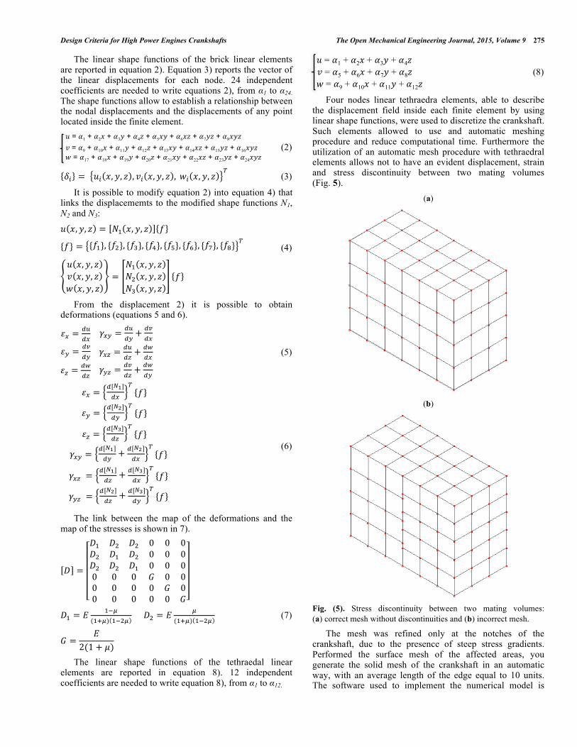
Four nodes linear tethraedra elements, able to describe the displacement field inside each finite element by using linear shape functions, were used to discretize the crankshaft. Such elements allowed to use and automatic meshing procedure and reduce computational time. Furthermore the utilization of an automatic mesh procedure with tethraedral elements allows not to have an evident displacement, strain and stress discontinuity between two mating volumes (Fig. 5).
(a)
(b)
Fig. (5). Stress discontinuity between two mating volumes: (a) correct mesh without discontinuities and (b) incorrect mesh.
The mesh was refined only at the notches of the crankshaft, due to the presence of steep stress gradients. Performed the surface mesh of the affected areas, you generate the solid mesh of the crankshaft in an automatic way, with an average length of the edge equal to 10 units. The software used to implement the numerical model is

276 The Open Mechanical Engineering Journal, 2015, Volume 9 S. Baragetti
MSC Patran®. The FEM analysis were conducted with the solver MSC Nastran®. Fig. (6) shows the mesh refinement in the grooves fitting between the pin and the cheek. It is also noted that, moving away from those areas, the average size of the finite element becomes the one set by the algorithm for the automatic generation of the mesh [30]. The von Mises’ stress was used as the driving parameter for the mesh refinement. The maximum dimension of the tethraedral elements was halved at each mesh refinement and convergence was reached very quickly. Fig. (7) shows the diagram of convergence, to an horizontal asymptote, of the model in the most stressed area between crankpin and cheeks (Fig. 8).
Fig. (6). Detail of the finite element model of the crankshaft, and refinement between crankpin and cheeks.
Fig. (7). Evaluation of the accuracy of the model: progressive refinement of the model (model “number 5” is the correct one).
The mesh refinement in the areas where the stress gradient is high and the assessment of the correctness of the results are two operations necessary not to underestimate the stress state. Fig. (8) shows an incorrect assessment of the stress state in the connecting channel on the left side of the shaft, analyzed without a local mesh refinement, as compared to the right side with a more accurate refining [30]. Fig. (9) shows the effects of an incorrect asymmetric mesh on the distribution of the von Mises’ stresses of the component [30].
Fig. (8). Asymmetric incorrect (left side) mesh of the crankshaft.
Fig. (9). Contour of the von Mises equivalent stress [MPa].
The Finite element model of the crankshaft allows to map the stress state of the component in order to be able to apply a multiaxial fatigue resistance criterion such as the one of Gough and Pollard or the Sines’ one (see paragraph 6 for the fatigue assessment) [36].
4. TORSIONAL VIBRATIONS
The motor torque applied to the shaft is not constant in time but periodically variable and therefore can be decomposed into a Fourier series within an interval equal to the period. It can thus be seen as a sum of sinusoidal variable torque moments and increasing frequencies. The crankshaft constitutes a system able to vibrate torsionally; therefore it would be dangerous if one of these frequencies would coincide or be very close to the frequency of one of the

Design Criteria for High Power Engines Crankshafts The Open Mechanical Engineering Journal, 2015, Volume 9 277
harmonics of the engine. This is the situation of resonance and the amplitude tends to become infinite, in the absence of damping. This is in every way an extreme situation and hardly brings the displacements to infinity, since damping reduces the amplitude of the displacements even in conditions of resonance. The analysis of the torsional vibrations can be summarized in the following stages: - Reduction of the crankshaft to an equivalent system,
constituted by a straight shaft, elastic and without mass, on which the equivalent inertia to the masses actually applied to the shaft are positioned (Fig. 10). A comparison between the values obtained by the application of empirical literature formulas [2, 3] and the values obtained with the finite element models has to be done. The value of the moment of inertia of the crankshaft is easily obtainable with a 3D solid CAD modeler: this is in addition to the contribution of the inertial masses, and the masses of the rotating flywheel. It also assesses the inertia of the auxiliaries, namely the distribution, the tone wheel and the motor pulley, and enables calculation the equivalent inertia applied to the axis of rotation of [31-34].
- Application of Lagrange's equation to the equivalent lumped system [31-34]. The result is a system of eight equations in eight unknowns and the search for solutions is carried out through the determination of the eigenvalues and eigenvectors. This allows the determination of the frequencies of vibration of the system and their own modes of vibration. Follows the harmonic analysis of engine torque, due to the pressure of the gas and the forces of inertia. The
engine has, in each cylinder, and for a four-stroke engine, a pattern which is repeated every two turns. Being a periodic function of period 4π, it can be developed in Fourier series: the harmonic components are determined separately due to gas pressure and those due to inertia forces, which will be combined later.
- Considering the first two frequencies, we analyze the regimes of resonance, namely the conditions for which the frequency of one of the harmonic components of the engine coincides with one of the frequencies of the system [2].
- The torsional stresses resulting from the analysis have to be calculated, as a function of the rotation speed of the crankshaft [30-34]. The procedure described so far, is reintroduced if a torsional vibration damper is applied to the crankshaft. The latter is able to absorb and dissipate the work of vibration transferred from the harmonic exciter shaft, reducing, when properly sized, vibratory torsional stresses. The trend of the torsional stresses have reduced peaks thanks to the presence of the viscous damper.
The graph of Fig. (11) shows the trend of the torsional stresses introduced by the torsional vibration in the crankshaft, the result of the above analysis [30].
4.1. The Torsional Vibration Dampers
When a crankshaft is in resonance with one of the harmonic components of the engine, torsional vibratory stresses can assume values such as to cause, in a short time,
Fig. (10). Discretization of the crankshaft. !
I7
K6
K6
I6I3 I4I1 I2 I6
I1
K1
I4I3I2 I5 I6
K2 K3 K4 K5
K1 K4K2 K3 K5
I8
I7 I8
K7
K7

278 The Open Mechanical Engineering Journal, 2015, Volume 9 S. Baragetti
the rupture. This drawback can be avoided by applying a torsional vibration damper, able to absorb and dissipate the work of vibration transferred to the shaft by the harmonic exciting component. The damper currently mounted on the motor shaft in question is in a viscous fluid (Fig. 12, [30]). It is applied on the crankshaft end where the oscillation amplitudes are greater, the side opposite to the engine flywheel. The viscous damper is constituted by an inertial mass enclosed in a casing that is fixed to the crankshaft. The
interstices existing between the mass and the inner annular outer casing are filled by a viscous fluid, the viscosity of which decreases with increasing temperature. Between the internal mass and the casing there are no connections, for which the interaction between the two elements is entrusted to the viscous forces transmitted by the fluid interposed. Applying a damper of this type means applying a mass (flywheel) to the motor shaft. Such device reduces the
Fig. (11). Diagram of the torsional stresses.
Fig. (12). Damper with viscous fluid.

Design Criteria for High Power Engines Crankshafts The Open Mechanical Engineering Journal, 2015, Volume 9 279
amplitudes of vibration due to the energy dissipated by the forces of viscous friction. The discretization of the system with the damper is shown in Fig. (13) [30].
5. STRESS CONCENTRATION
The actual values of the stresses are generally higher than their nominal values because of the notch effect, namely the influence of the geometry of the crankshaft that could be the cause of stress concentrations. The crankshaft is subjected to both bending actions that torques: a stress concentration factor for bending stresses kf and one for torsional stresses kt have to be used. The areas were the crankshaft connecting rods are mounted represent the most stressed zones of the crankshaft. The stress concentration factor for bending kf is defined as the ratio between the maximum bending stress and the nominal bending stress in 9):
kf =
σ max
σ nom
(9)
The only condition to be met is that the material, assumed homogeneous and isotropic, has a linear elastic behavior. With this hypothesis kf depends only on the geometry of the component. The value of the nominal stress at the crankpin, the area where the stress state reaches the maximum values, can be calculated with equation 10):
σ nom =
Mf
Wf
=32 ⋅Mf
π ⋅Db3 ≈ 0.04 MPa (10)
where: Mf = 1000 Nmm = applied bending moment Db = 63.5 mm = diameter of the crank pin Wf = bending strength modulus Finite element analysis can be used to evaluate the maximum stress generated by the bending load. The constraints and loads applied to finite element model are represented in Fig. (14). The constraints of the finite element prevent any translations along the axes X, Y, Z of the nodes belonging to the surface of the bearing pin, perpendicular to the axis of rotation of the shaft. At the opposite surface the unit bending moment was applied by using an MPC (Multi-point constraint). The latter is capable of transmitting forces and/or bending actions from a node, placed in the center of the surface of application of the load, to all the independent nodes belonging to the surface itself, as if it were really a bending moment applied to the pin counter. Fig. (15) shows the structure of the MPC element [30].
Fig. (14). FEM model of the crankshaft used for the calculation of kf.
Fig. (15). Particular of the MPC constraint.
The analysis confirms that the maximum stress state occurs at the connecting channels between crankpin and their cheeks. Fig. (16) shows the stress state along the Z axis [30].
Fig. (16). Stress state induced by a unitary bending moment, σZ [MPa].
The maximum stress is equal to:
Fig. (13). Discretization of the system with damper. !
I1 I4I3I2 I5 I6 I7 I8I0r1
K4K0
K2K1 K3 K6K5 K7
280 The Open Mechanical Engineering Journal, 2015, Volume 9 S. Baragetti
σ max,Z = 0.20 MPa
It is now possible to calculate the bending stress concentration factor:
Kf =
σ max,Z
σ nom
= 0.200.04
= 5
6. FATIGUE ASSESSMENT
The analysis of the kinematics of the crank mechanism is required for the calculation of the accelerations of the foot of the connecting rod. By using the values of the pressure of the gases in the combustion chamber, a function of crank angle (determined experimentally), we can calculate the actions exerted by the gases on the pistons themselves. The sum of the two contributions, inertial and pressure, gives the force transmitted by the connecting rod, which can be divided into a radial and a tangential component (Fig. 17, [30]).
Fig. (17). Components of the forces exchanged at the crank pin.
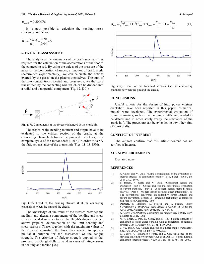
The trends of the bending moment and torque have to be evaluated in the critical section of the crank, at the connecting channels between the pin and the cheek, in a complete cycle of the motor shaft (720 °) in order to verify the fatigue resistance of the crankshaft (Figs. 18, 19, [30]).
Fig. (18). Trend of the bending stresses σ at the connecting channels between the pin and the cheek.
The knowledge of the trend of the stresses provides the medium and alternate components of the bending and shear stresses, needed in order to use the Haigh’s diagram, which allows graphical determination of the limit bending and shear stresses. These, together with the maximum values of the stresses, constitute the basic data needed to apply a multiaxial criterion for the assessment of the fatigue strength. The criterion of fatigue strength applied is that proposed by Gough-Pollard, valid in cases of fatigue stress in bending and torsion [36].
σ GP = σ 2
max + H2τ 2max ≤σ amm =
σ lim
η H =
σ lim
τ lim
(11)
Fig. (19). Trend of the torsional stresses τ at the connecting channels between the pin and the cheek.
CONCLUSIONS
Useful criteria for the design of high power engines crankshaft have been reported in this paper. Numerical models were developed. The experimental evaluation of some parameters, such as the damping coefficient, needed to be determined in order safely verify the resistance of the crankshaft. The procedure can be extended to any other kind of crankshafts.
CONFLICT OF INTEREST
The authors confirm that this article content has no conflict of interest.
ACKNOWLEDGEMENTS
Declared none.
REFERENCES
[1] A. Garro, and V. Vullo, “Some consideration on the evaluation of thermal stresses in combustion engine”, SAE, Paper 780664, pp. 2563-2592, 1978.
[2] E. Bargis, A. Garro and V. Vullo, “Crankshaft design and evaluation - Part 1 - Critical analysis and experimental evaluation of current methods, - Part 2 - A modern design method: modal analysis - Part 3 - Modern design method: direct integration”, In: The international conference on reliability, stress analysis and failure prevention, century 2 - emerging technology conferences, San Francisco, California, 1980.
[3] Delprete, R. Molisano, D. Micelli, and E. Pisanò, Analisi Vibrazionale e Strutturale degli Alberi a Gomiti, in Convegno AIAS 2001, Alghero, Italy, 2001, pp. 1427-1435.
[4] A. Garro, Progettazione Strutturale del Motore, Ed. Torino, Italy: Levrotto & Bella, 1992.
[5] W.Y. Chien, J. Pan, D. Close, and S. Ho, “Fatigue analysis of crankshaft sections under bending with consideration of residual stresses”, Int. J. Fatigue, vol. 27, pp. 1-19, 2005.
[6] Z. Yu, and X. Xu, “Failure analysis of a diesel engine crankshaft”, Eng. Fail. Anal., vol. 12, pp. 487-495, 2005.
[7] G. Castro, A. Fernandez-Vicente, and J. Cid, “Influence of the nitriding time in the wear behaviour of an AISI H13 steel during a crankshaft forging process”, Wear, vol. 263, pp. 1375-1385, 2007.
!
α
βFb R
T A
α+β
a

Design Criteria for High Power Engines Crankshafts The Open Mechanical Engineering Journal, 2015, Volume 9 281
[8] S. Ho, Y.-L. Lee, H.-T. Kang, and C. J. Wang, “Optimization of a crankshaft rolling process for durability”, Int. J. Fatigue, vol. 31, pp. 799-808, 2009.
[9] U. Jung, R. Schaal, C. Berger, H.-W. Reinig, and H. Traiser, “Predicting the fatigue strength of fillet-rolled crankshafts”, Mat.-wiss. u. Werkstofftech., vol. 29, pp. 569-572, 1998.
[10] K.S. Choi, and J. Pan, “Simulations of stress distributions in crankshaft sections under fillet rolling and bending fatigue tests”, Int. J. Fatigue, vol. 31, pp. 544-557, 2009.
[11] S. Y. Sirina, K. Sirinb, and E. Kalucc, “Effect of the ion nitriding surface hardening process on fatigue behaviour of AISI 4340 steel”, Mater. Charact., vol. 59, pp. 351-358, 2008.
[12] R. Koneèná, G. Nicoletto, and V. Majerová, “Influence of nitriding on the fatigue behavior and fracture micromechanisms of nodular cast iron”, Struct Mater., vol. 40, no. 1, pp.75-78, 2008.
[13] Y. Furuya, H. Hirukawa, S. Matsuoka, S. Torizuka, and H. Kuwahara, “Fatigue properties of nitrided ultrafine ferrite-cementite steels under rotating bending fatigue testing”, Metall. Mater. Trans. A, vol. 39, pp. 2068-2076, 2008.
[14] American Society for Metals, Metals Handbook. Metallography and Microstructures of Case-Hardening Steel, ASM International, Metals Park, Ohio, vol. 9, 2004.
[15] S. Baragetti, and L. Molinari, “Resistenza a fatica e tensioni residue in elementi meccanici nitrurati: risultati numerici e sperimentali”, Degree thesis, Politecnico di Milano, Milano, Italy, 1994.
[16] S. Baragetti, G. M. La Vecchia, and A. Terranova, “Variables affecting the fatigue resistance of PVD-coated components”, Int. J. Fatigue, vol. 27, no. 10-12, pp.1541-1550, 2005.
[17] S. Baragetti, “Fatigue resistance of steel and titanium PVD coated spur gears”, Int. J. Fatigue, vol. 29, pp. 1893-1903, 2007.
[18] J. Vetter, G. Barbezat, J. Crummenauer, and J. Avissar, “Surface treatment selections for automotive applications”, Surf. Coat. Technol., vol. 200, pp. 1962-1968, 2005.
[19] Y.L. Su, S.H. Yao, C.S. Wei, W.H. Kao, and C.T. Wu, “Comparison of wear, tensile, and fatigue properties of PVD coated materials”, Mater. Sci. Technol., vol. 15, pp. 73-77, 1999.
[20] D. Siano, and R. Citarella, “Elastic multi body simulation of a multi-cylinder engine”, Open Mech. Eng. J., vol. 8, pp. 157-169, 2014.
[21] Z.-F. Bai, B.-j. Yang, and Y. Sun, “Investigation on dynamics of mechanical system with clearance joint”, Open Mech. Eng. J., vol. 8, pp. 224-229, 2014.
[22] B. Zheng, Y. Liu, and R. Liu, “Stress and fatigue of connecting rod in light vehicle engine”, Open Mech Eng. J., vol. 7, pp. 14-17, 2013.
[23] S. Baragetti, S. Mori, and E. Scarabotto, “A study on connecting rods for IC engines”, Int. J. Comput. Appl. Technol., vol. 26, no. 3, pp. 126-136, 2006.
[24] Y. Wang, and H. Gao, “Research on optimization for the piston pin and the piston pin boss”, Open Mech. Eng. J., vol. 5, pp. 186-193, 2011.
[25] M. Guagliano, A. Terranova, and L. Vergani, “Theoretical and experimental study of the stress concentration factor in diesel engine crankshafts”, J. Mech. Des., vol. 115, pp. 47-52, 1993.
[26] S. Baragetti, S. Cavalleri, and A. Terranova, “A numerical and experimental investigation on the fatigue behaviour of a steel nitrided crankshaft for high power IC engines”, ASME J. Eng. Mater. Technol., vol. 32, July 2010.
[27] V. Leskovšeka, B. Podgornik, and D. Nolan, “Modelling of residual stress profiles in plasma nitrided tool steel”, Mater. Charact., vol. 59, pp. 454-461, 2008.
[28] C.H. Gur, “Investigation of the influence of specimen geometry on quench behaviour of steels by X-ray determination of surface residual stresses”, Int. J. Mech. Sci., vol. 44, pp. 1335-1347, 2002.
[29] J. A. Martins, L. P. Cardoso, J. Al. Fraymann, and S. T. Button, “Analyses of residual stresses on stamped valves by X-ray diffraction and finite elements method”, J. Mat. Proc. Techol., vol. 179, pp. 30-35, 2006.
[30] S. Baragetti, L. Crippa, and E. Scarabotto, “Studio numerico di alberi a gomiti”, Progettare, n° 284, Ed. Gruppo Editoriale Jackson, December 2004.
[31] W. Ker Wilson, Torsional vibration problems, Volume one: frequency calculations, Ed. London: Chapman & Hall, 1965.
[32] W. Ker Wilson, Torsional vibration problems, Volume two: amplitude calculations, Ed. London: Chapman & Hall, 1965.
[33] W. Ker Wilson, Torsional vibration problems, strength calculations, Ed. London: Chapman & Hall, vol. 3, 1965.
[34] W. Ker Wilson, Torsional vibration problems, device for controlling vibration, Ed. London: Chapman & Hall, vol. 4, 1965.
[35] G. Belingardi, “Il metodo degli elementi finite nella progettazione meccanica”, Ed. Torino: Levrotto & Bella, 1999.
[36] R. L. Norton, Machine Design, Ed. New Jersey: Prentice Hall, 2013.
Received: January 8, 2015 Revised: January 15, 2015 Accepted: January 16, 2015 © S. Baragetti; Licensee Bentham Open.
This is an open access article licensed under the terms of the Creative Commons Attribution Non-Commercial License (http://creativecommons.org/licenses/by-nc/3.0/) which permits unrestricted, non-commercial use, distribution and reproduction in any medium, provided the work is properly cited.