the origins of fiber optic communicationsdanielb/emwaves_part7.pdfintroduction • an optical fiber...
TRANSCRIPT

Optical Fibers
Basics, applications,

Introduction
• An optical fiber is essentially a waveguide for light• It consists of a core and cladding that surrounds the core• The index of refraction of the cladding is less than that of the core,
causing rays of light leaving the core to be refracted back into the core• A light-emitting diode (LED) or laser diode (LD) can be used for the
source• Advantages of optical fiber include:
– Greater bandwidth than copper– Lower loss– Immunity to crosstalk– No electrical hazard

Fiber v. Copper
• Optical fiber transmits light pulses
– Can be used for analog or digital transmission
– Voice, computer data, video, etc.
• Copper wires (or other metals) can carry the
same types of signals with electrical pulses

Advantages of Fiber
• Fiber has these advantages compared with
metal wires
– Bandwidth – more data per second
– Longer distance
– Faster
– Special applications like medical imaging and
quantum key distribution are only possible with
fiber because they use light directly

Optical Fiber• Core
– Glass or plastic with a higher index of
refraction than the cladding
– Carries the signal
• Cladding
– Glass or plastic with a lower index of
refraction than the core
• Buffer
– Protects the fiber from damage and
moisture
• Jacket
– Holds one or more fibers in a cable

Optical Fiber
• Optical fiber is made from thin strands of either glass or plastic
• It has little mechanical strength, so it must be enclosed in a protective jacket
• Often, two or more fibers are enclosed in the same cable for increased bandwidth and redundancy in case one of the fibers breaks
• It is also easier to build a full-duplex system using two fibers, one for transmission in each direction

Total Internal Reflection
• Optical fibers work on the principle of total internal reflection
• With light, the refractive index is listed
• The angle of refraction at the interface between two media is governed by Snell’s law:
n1 sin1 n2 sin2

Refraction & Total Internal Reflection

Optical rays transmission through
dielectric slab waveguide
ccnn
2
;21
sin
cos
2
sintan
1
2
2
22
11
n
nnmdn
For TE-case, when electric waves are normal to the plane of incidencemust be satisfied with following relationship:
O

Numerical Aperture• The numerical aperture of the fiber
is closely related to the critical angle and is often used in the specification for optical fiber and the components that work with it
• The numerical aperture is given by the formula:
• The angle of acceptance is twice that given by the numerical aperture
2
2
2
1.. nnAN

Modes and Materials
• Since optical fiber is a waveguide, light can propagate in a number of modes
• If a fiber is of large diameter, light entering at different angles will excite different modes while narrow fiber may only excite one mode
• Multimode propagation will cause dispersion, which results in the spreading of pulses and limits the usable bandwidth
• Single-mode fiber has much less dispersion but is more expensive to produce. Its small size, together with the fact that its numerical aperture is smaller than that of multimode fiber, makes it more difficult to couple to light sources

Types of Fiber
• Both types of fiber described earlier are known as step-index fibers because the index of refraction changes radically between the core and the cladding
• Graded-index fiber is a compromise multimode fiber, but the index of refraction gradually decreases away from the center of the core
• Graded-index fiber has less dispersion than a multimode step-index fiber

Singlemode Fiber
• Singlemode fiber has a core diameter of 8 to 9
microns, which only allows one light path or
mode
Index of refraction

Multimode Step-Index Fiber• Multimode fiber has a core diameter of 50 or
62.5 microns (sometimes even larger)
– Allows several light paths or modes
– This causes modal dispersion – some modes take longer to
pass through the fiber than others because they travel a
longer distance
– See animation at link Ch 2f Index of refraction

Multimode Graded-Index Fiber
• The index of refraction gradually changes
across the core– Modes that travel further also move faster
– This reduces modal dispersion so the bandwidth is greatly
increased
Index of refraction
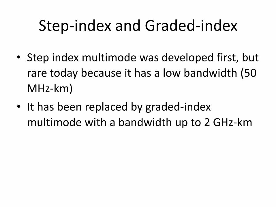
Step-index and Graded-index
• Step index multimode was developed first, but
rare today because it has a low bandwidth (50
MHz-km)
• It has been replaced by graded-index
multimode with a bandwidth up to 2 GHz-km

Mathematical approach

Modal Theory of Step Index fiber
• General expression of EM-wave in the circular fiber can be written as:
• Each of the characteristic solutions is
called mth mode of the optical fiber.
• It is often sufficient to give the E-field of the mode.
m
ztj
mm
m
mm
m
ztj
mm
m
mm
m
m
erVAtzrHAtzrH
erUAtzrEAtzrE
)ω(
)ω(
),(),,,(),,,(
),(),,,(),,,(
),,,( & ),,,( tzrHtzrE mm
1,2,3...m ),()ω(
ztj
mmerU

• The modal field distribution, , and the mode
propagation constant, are obtained from solving the
Maxwell’s equations subject to the boundary conditions given
by the cross sectional dimensions and the dielectric constants
of the fiber.
• Most important characteristics of the EM transmission along the fiber are
determined by the mode propagation constant, , which depends on
the mode & in general varies with frequency or wavelength. This quantity
is always between the plane propagation constant (wave number) of the
core & the cladding media .
),( rUm
m
)ω(m
knkn m 12 )ω(

• At each frequency or wavelength, there exists only a finite number of
guided or propagating modes that can carry light energy over a long
distance along the fiber. Each of these modes can propagate in the fiber
only if the frequency is above the cut-off frequency, , (or the source
wavelength is smaller than the cut-off wavelength) obtained from cut-off
condition that is:
• To minimize the signal distortion, the fiber is often operated in a single
mode regime. In this regime only the lowest order mode (fundamental
mode) can propagate in the fiber and all higher order modes are under cut-
off condition (non-propagating).
• Multi-mode fibers are also extensively used for many applications. In
these fibers many modes carry the optical signal collectively &
simultaneously.
cω
kncm 2)ω(

Fundamental Mode Field Distribution
Optical Fiber communications, 3rd ed.,G.Keiser,McGrawHill, 2000
Polarizations of fundamental modeMode field diameter

Mode designation in circular cylindrical
waveguide (Optical Fiber)
:modesEH Hybrid
:modesHE Hybrid
:modesTM
:modes TE
lm
lm
lm
lm The electric field vector lies in transverse plane.
The magnetic field vector lies in transverse plane.
TE component is larger than TM component.
TM component is larger than TE component.
l= # of variation cycles or zeros in direction.
m= # of variation cycles or zeros in r direction.
x
y
r
z
Linearly Polarized (LP) modes in weakly-guided fibers ( )121 nn
)HETMTE(LP),HE(LP 000110 mmmmmm
Fundamental Mode: )HE(LP 1101

Two degenerate fundamental modes in
Fibers (Horizontal & Vertical Modes)11HE
Optical Fiber communications, 3rd ed.,G.Keiser,McGrawHill, 2000

Mode propagation constant as a function of
frequency
• Mode propagation constant, , is the most important transmission
characteristic of an optical fiber, because the field distribution can be easily
written in the form of eq. [2-27].
• In order to find a mode propagation constant and cut-off frequencies of
various modes of the optical fiber, first we have to calculate the
normalized frequency, V, defined by:
ω)(lm
NA22 2
2
2
1
ann
aV [2-30]
a: radius of the core, is the optical free space wavelength,
are the refractive indices of the core & cladding.
21 & nn

V-Number and Fiber Modes
ligthofwavelength
coreofradiusa
NAaV
:
:
/2
2.405

Cut-off Wavelength
Definition: the wavelength below which multiple modes of light can be propagated along a particular fiber, i.e., >=c, single mode, <c, multi-mode
NAa
c 405.2
2

Single mode Operation
• The cut-off wavelength or frequency for each mode is obtained from:
• Single mode operation is possible (Single mode fiber) when:
2
)ω( 2c22
c
nnkn
c
clm
405.2V
fiber optical along faithfully propagatecan HEOnly 11

Birefringence in single-mode fibers
• Because of asymmetries the refractive indices for the two degenerate modes
(vertical & horizontal polarizations) are different. This difference is referred to as
birefringence, :fB
xyf nnB

Fiber Beat Length
• In general, a linearly polarized mode is a combination of both of the
degenerate modes. As the modal wave travels along the fiber, the difference
in the refractive indices would change the phase difference between these
two components & thereby the state of the polarization of the mode.
However after certain length referred to as fiber beat length, the modal
wave will produce its original state of polarization. This length is simply
given by:
fkBL
2B

Multi-Mode Operation
• Total number of modes, M, supported by a multi-mode fiber is
approximately (When V is large) given by:
• Power distribution in the core & the cladding: Another quantity of
interest is the ratio of the mode power in the cladding, to the total
optical power in the fiber, P, which at the wavelengths (or frequencies) far
from the cut-off is given by:
2
2VM
cladP
MP
Pclad
3
4

Sources and Wavelengths
• Multimode fiber is used with
– LED sources at wavelengths of 850 and 1300 nm
for slower local area networks
– Lasers at 850 and 1310 nm for networks running
at gigabits per second or more

Sources and Wavelengths
• Singlemode fiber is used with
– Laser sources at 1300 and 1550 nm
– Bandwidth is extremely high, around 100 THz-km

Fiber Optic Specifications
• Attenuation– Loss of signal, measured in dB
• Dispersion– Blurring of a signal, affects bandwidth
• Bandwidth– The number of bits per second that can be sent
through a data link
• Numerical Aperture– Measures the largest angle of light that can be
accepted into the core


Measuring Bandwidth
• The bandwidth-distance product in units of
MHz×km shows how fast data can be sent
through a cable
• A common multimode fiber with bandwidth-
distance product of 500 MHz×km could carry
– A 500 MHz signal for 1 km, or
– A 1000 MHz signal for 0.5 km• From Wikipedia

Popular Fiber Types
• At first there were only
two common types of fiber
– 62.5 micron multimode, intended for LEDs and 100
Mbps networks
• There is a large installed base of 62.5 micron fiber
– 8 micron single-mode for long distances or high
bandwidths, requiring laser sources
• Corning’s SMF-28 fiber is the largest base of installed
fiber in the world.

Gigabit Ethernet
• 62.5 micron multimode fiber did not have
enough bandwidth for Gigabit Ethernet (1000
Mbps)
• LEDs cannot be used as sources for Gigabit
Ethernet – they are too slow
• So Gigabit Ethernet used a new, inexpensive
source:
– Vertical Cavity Surface Emitting Laser (VCSEL)

Other types of optical fibers

Birefringent Fiber (Bow-Tie)
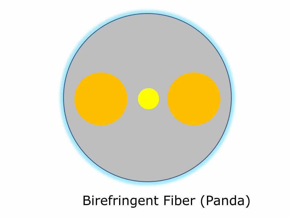
Birefringent Fiber (Panda)

2 symmetry axes (birefringence axes)
Only one polarization mode is excited
Linear polarization propagates unchanged
0°

2 symmetry axes (birefringence axes)
45°Two polarization modes are excited
Linear polarization is changing periodically

The Beat Lengththe length corresponding to full evolution of state of polarization

Masuring the Beat Length
P /2 A
detector
Micrometric
manipulator
Laser
diode
Δl
l
objective
45°

Results
0
0,2
0,4
0,6
0,8
1
1,2
0 100 200 300 400 500 600 700
me
Sig
nal [a
.u]

46
• Frequently there is the need to temporarily or permanently joint two pieces of fiber. To achieve this, many different types and styles of mechanical assemblies have been designed.
• Many types of connectors were designed based on cost and performance as the key objectives.
• Merits of each connector are in the ability to hold the close tolerances necessary for good connection and in the repeatability of multiple connections.
Connectors & Splices

Fiber-Optic Connectors• Coupling the fiber to sources and
detectors creates losses as well, especially when it involves mismatches in numerical aperture or in the size of optical fibers
• Good connections are more critical with single-mode fiber, due to its smaller diameter and numerical aperture
• A splice is a permanent connection and a connector is removable

• FC and SC connectors are the most common in domestic market, ST connectors are mostly used in telephony applications and E-2000 is popular overseas.
Common Connector Types

49
• The differences in connectors types are mainly in the mechanical assembly that holds the ferrule in position against another, identical ferrule.
• The FC, SC and ST are all examples of physically contacting (PC) connectors. Physically contacted is where the fiber ends are mated in physical contact with each other.
Physical Contact Connectors

50
• Physical Contact connectors are polished with a convex shape that is meant to slightly deform when two connectors are brought together.
Physical Contact Connectors
PC Connectors Prior to Mating
PC Connectors After Mating

51
• Ultra Polished connectors (UPC) have a flat end surface where both the ceramic and fiber are polished to the same plain.
• The UPC connector provides very low insertion losses, however, whatever light is reflected will propagate back toward the source.
• UPC connectors are typically used near receivers, since and back reflections will be attenuated as they propagate back through the fiber.
UPC Ferrule Configuration

52
• Angled Polished connectors (APC) are polished with an 8 end surface angle.
• The APC has slightly higher insertion losses than the UPC style, however the angled end directs back reflections into the cladding.
• APC connectors are typically used near sources (i.e. transmitters or EDFAs) where back reflections will quickly reduce system performance.
APC Ferrule Configuration

53
• Angular misalignment caused by mating an APC connector to a UPC connector is extremely common and will cause approximately 3-5 dB of attenuation.
Common Connector Faults
NA1
NA2
Lateral Offset
End Separation
Numerical Aperture Mismatch
Angular Misalignment
Angular Misalignment
Core Diameter Mismatch

54
Fusion splices are created by heating both fiber ends with a high current electric arc and then bringing them into contact with one another.
Fusion splices are permanent and have extremely low loss
Splice loss is typically 0.02db
Fusion Splice equipment is expensive and can be difficult to use in the field
Fusion Splices
Strength Member
Fiber ends are melted (fused) together
Heat Shrink

55
Fiber ends are butted together and mechanically locked into place in a funneled capillary.
Inside the tube is a small amount of Index Matching Gel that reduces the amount of reflection at the fiber ends interface.
Mechanical Splices can be permanent or reusable, but splice loss is typically 0.1db to 0.2db and degrades with each use.
Splice tubes are less than $10.00
Mechanical Splices
Index Matching Gel
Capillary Tube

Optical Couplers and Switches
• As with coaxial cable and microwave waveguides, it is possible to build power splitters and directional couplers for fiber-optic systems
• It is more complex and expensive to do this with fiber than with copper wire
• Optical couplers are categorized as either star couples with multiple inputs and outputs or as tees, which have one input and two outputs

Coupler Construction
• Optical couplers can be made in many different ways:
– A number of fibers can be fused together to make a transmissive coupler
– A reflective coupler allows a signal entering on any fiber to exit on all other fibers, so the coupler is bidirectional

Optical Switches and Relays• Occasionally, it is necessary to switch
optical signals from one fiber to another• The simplest type of optical switch
moves fibers so that an input fiber can be positioned next to the appropriate output fiber
• Another approach is direct the incoming light into a prism, which reflects it into the outgoing fiber. By moving the prism, the light can be switched between different output fibers
• Lenses are necessary with this approach to avoid excessive loss of light

Don’t Mix Fiber Types
• You can’t mix singlemode and multimode fiber
– you lose 20 dB at the junction (99% of the
light!)
• Mixing 50 micron and 62.5 micron multimode
is not as bad, but you lose 3 dB (half the
power) which is usually unacceptable

Fiber Manufacture

Three Methods
• Modified Chemical Vapor Deposition (MCVD)
• Outside Vapor Deposition (OVD)
• Vapor Axial Deposition (VAD)

Modified Chemical Vapor Deposition
(MCVD)
• A hollow, rotating glass tube is
heated with a torch
• Chemicals inside the tube
precipitate to form soot
• Rod is collapsed to crate a
preform
• Preform is stretched in a
drawing tower to form a single
fiber up to 10 km long

Outside Vapor Deposition (OVD)
• A mandrel is coated with a porous preform in a furnace
• Then the mandrel is removed and the preform is collapsed in a process called sintering– Image from csrg.ch.pw.edu.pl

Vapor Axial Deposition (VAD)
• Preform is fabricated continuously
• When the preform is long enough, it goes directly to the drawing tower– Image from csrg.ch.pw.edu.pl

Drawing
• The fiber is drawn from the preform and then coated with a protective coating

Index of Refraction
• When light enters a dense medium like glass or water, it slows down
• The index of refraction (n) is the ratio of the speed of light in vacuum to the speed of light in the medium
• Water has n = 1.3
– Light takes 30% longer to travel through it
• Fiber optic glass has n = 1.5
– Light takes 50% longer to travel through it

Fiber Applications
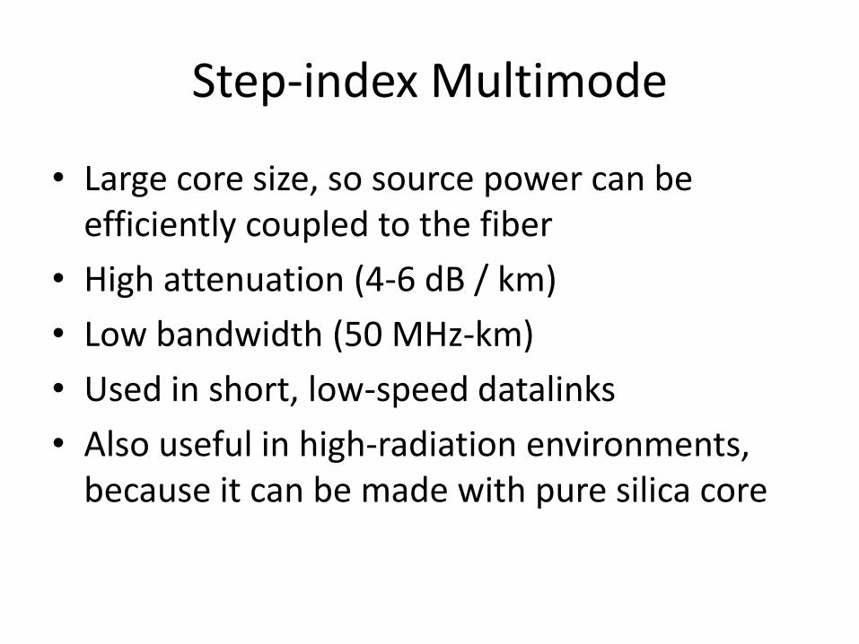
Step-index Multimode
• Large core size, so source power can be efficiently coupled to the fiber
• High attenuation (4-6 dB / km)
• Low bandwidth (50 MHz-km)
• Used in short, low-speed datalinks
• Also useful in high-radiation environments, because it can be made with pure silica core

Graded-index Multimode
• Useful for “premises networks” like LANs, security systems, etc.
• 62.5/125 micron has been most widely used
– Works well with LEDs, but cannot be used for Gigabit Ethernet
• 50/125 micron fiber and VSELS are used for faster networks

Three Types of Dispersion
• Dispersion is the spreading out of a light pulse as it travels through the fiber
• Three types:
– Modal Dispersion
– Chromatic Dispersion
– Polarization Mode Dispersion (PMD)

Modal Dispersion
• Modal Dispersion
– Spreading of a pulse because different modes (paths) through the fiber take different times
– Only happens in multimode fiber
– Reduced, but not eliminated, with graded-index fiber

Chromatic Dispersion
• Different wavelengths travel at different speeds through the fiber
• This spreads a pulse in an effect named chromatic dispersion
• Chromatic dispersion occurs in both singlemode and multimode fiber– Larger effect with LEDs than with lasers
– A far smaller effect than modal dispersion
Polarization Mode Dispersion
• Light with different polarization can travel at different speeds, if the fiber is not perfectly symmetric at the atomic level
• This could come from imperfect circular geometry or stress on the cable, and there is no easy way to correct it
• It can affect both singlemode and multimode fiber.

Modal Distribution
• In graded-index fiber, the off-axis modes go a longer distance than the axial mode, but they travel faster, compensating for dispersion
– But because the off-axis modes travel further, they suffer more attenuation
Equilibrium Modal Distribution
• A long fiber that has lost the high-order modes is said to have an equilibrium modal distribution
• For testing fibers, devices can be used to condition the modal distribution so measurements will be accurate

Optical Line Amplification
1 2 3 4 5 6 7 8 16
...
Attenuated Channels
1 2 3 4 5 6 7 8 16
...
Amplified Channels
All Wavelengths Amplified with One Amplifier

EDFA Operation
(980 and 1480 nm)
pump signal input
1550 nmbandsignalinput
Erbium Doped Fiber
amplified
spontaneous
emissions
amplified
spontaneous
emissions
pump signal output
(980 and 1480 nm)
1550 nmbandsignaloutput
-80
-70
-60
-50
-40
-30
-20
1500 1520 1540 1560 1580 1600
wavelength
dB
m
Spectrum of a typical EDFA

78
EDFA Operation
4I15/2
4I13/2
4I11/2
4I9/2
4F9/2
1480nm
1536nm
980nm
800nm
650nm
• Pump lasers (typically 980nm and 1480nm) are used to excite the Erbium
doped fiber to a higher energy state.
• Pump lasers (typically 980nm and 1480nm) are used to excite the Erbium
doped fiber to a higher energy state.
• The Erbium fiber resides in the 4I-13/2 state until triggered by a passing
1550nm photon, at which time a duplicate photon is released.

79
OpticalInput
OpticalOutput
Er+3
OPTICAL AMPLIFIER CONTROLLER
PUMPLASER
PUMPLASER
PD PDT
Isolator IsolatorWDM(1550/980) WDM
EDFA
• Erbium Doped Fiber Amplifiers (EDFAs) are the amplification device most
commonly used in fiber systems.

Decibel Units

Optical Loss in dB (decibels)
• If the data link is perfect, and loses no power
– The loss is 0 dB
• If the data link loses 50% of the power
– The loss is 3 dB, or a change of – 3 dB
• If the data link loses 90% of the power
– The loss is 10 dB, or a change of – 10 dB
• If the data link loses 99% of the power
– The loss is 20 dB, or a change of – 20 dB
dB = 10 log (Power Out / Power In)
Data LinkPower In Power Out

Absolute Power in dBm
• The power of a light is measured in milliwatts
• For convenience, we use the dBm units, where
-20 dBm = 0.01 milliwatt
-10 dBm = 0.1 milliwatt
0 dBm = 1 milliwatt
10 dBm = 10 milliwatts
20 dBm = 100 milliwatts

• 2-D photonic crystal with defect near the core region along the fiber
axis
• Structure made of one type of glass with the matrix of periodically
placed micro-chanels forming a photonic crystal structure.
birefringent Hollow-core nonlinear isotropic
Photonic Crystal Fibers