the oxygen refuse converter - a system for producing fuel gas, oil
TRANSCRIPT

The Oxygen Refuse Converter - A System for Producing Fuel Gas, Oil, Molten Metal
and Slag .from Refuse J. E. ANDERSON
Union Carbide Corporation
Tarrytown, N.Y.
INTRODUCTION
Several years ago, an investigation was undertaken to apply the extensive background in the use of oxygen for high temperature and metallurgical processes to the problem of solid waste disposal. The ultimate goal of this investigation was to come forth with a process which would be a significant advance both in reducing substantially the pollution associated with prior methods of solid waste disposal and in utilizing the refuse realistically as a source of raw material. This investigation has culminated in the development of the PUROX* System [1).
The heart of the system is the oxygen converter which is a shaft furnace for converting the refuse into fuel gas and a stream of molten metal and glass. A schematic diagram of the furnace is pictured in Fig. 1. Solids descend the furnace starting as refuse feed at the top and ending as molten residue flowing out the bottom. Gases rise countercurrent to the descending solids with oxygen being fed in at the bottom and fuel gas exiting at the top. The shaft furnace can be divided into three zones: a combustion and melting zone at the bottom, a pyrolysis zone in the middle, and a drying zone at the top. Oxygen entering the combustion and melting zone reacts with the descending char to form predominantly carbon monoxide. The heat of combustion is sufficient to maintain a temperature of about 3000°F at the bottom of the furnace and to melt the inorganic portion of the residue forming a molten metal phase and a molten slag phase. The hot
'UNION CARBIDE TRADEMARK
combustion gases rise in the furnace into the pyrolysis zone. In this zone the organic portion of the refuse (mostly cellulose from paper products) is heated by the hot combustion products causing thermal breakdown into gas (mainly CO, CO2, H2 , CH4 and H20), soluble organic compounds, oil and char. The char descends into the combustion and melting zone to act as fuel. The gas and oil pass up to the drying zone where the remaining sensible heat is utilized to dry the incoming refuse. The gas leaves the furnace at a temperature usually ranging from 170 to 200°F. It has a heating value on a dry basis of about 300 BTU/CF. The overall operation is very efficient thermally.
The oxygen converter is unique in that is combines the advantages of i) high temperature incineration to con
. vert the inorganic residue to molten metal and glass and ii) pyrolysis to produce oil and fuel gas.
An important feature of the process is that the off gas can be cleaned immediately upon leaving the shaft furnace. By cleaning the gas at this point, rather than burning it to completion as commonly practiced in most other disposal systems, advnatage is taken of the low gas volume. Because of the low gas volume, less than one
337
tenth that from a conventional incinerator, the size of the gas cleaning equipment is correspondingly reduced. In addition, the amount of pollutants present in the gas after cleaning is reduced by an order of magnitude compared to conventional incineration for each ton of refuse consumed. The product gas after cleaning is a useful fuel gas essentially free of fly ash and low in sulfur. The gas can be used as a fuel by utilities, industry, etc. without the corrosion and erosion problems normally associated with heat recovery systems using municipal refuse as a fuel.

FUEL GAS OUT
REFUSE ,.---- FEED IN
_....L... ___ -1-_"
I-DRYING
ZONE
t----------(
OXYGEN ----' IN
�PYROLYSIS
ZONE
'" ....
COMBUSTION & MELTING
ZONE
MOLTEN METAL AN D G LASS OUT
FIG. 1 SCHEMATIC DIAGRAM OF SHAFT FURNACE
A 5 ton/day pilot unit was constructed to prove out the process and to determine the necessary design information for construction of a full scale plant. The results of this investigation, are summarized in this paper.
REFUSE:..-, FEED
OFF GAS FUEL GAS
OIL
DESCRIPTION OF THE PILOT UNIT
A block diagram of the overall pilot unit is shown in Fig. 2. Refuse and oxygen were fed into the shaft furnace at the top and bottom, respectively. At the bottom of the furnace a stream of molten metal and glass was continuously tapped and quenched with water in the slag collector to form a granulated residue. At the top of the furnace; the off gas containing the fuel gas, water vapor, oil mist and a small amount of fly ash flowed directly into an electrostatic precipitator. The oil mist and fly ash were separated from the gas in the precipitator. The oil was either removed from the system for analyses and combustion tests or it was recirculated to the bottom of the furnace where it was thermally cracked and gasified. The off gas leaving the precipitator entered a condenser to remove most of the water vapor. Since the pilot unit was not equipped to use the fuel gas, the gas leaving the condenser was flared to the atmosphere.
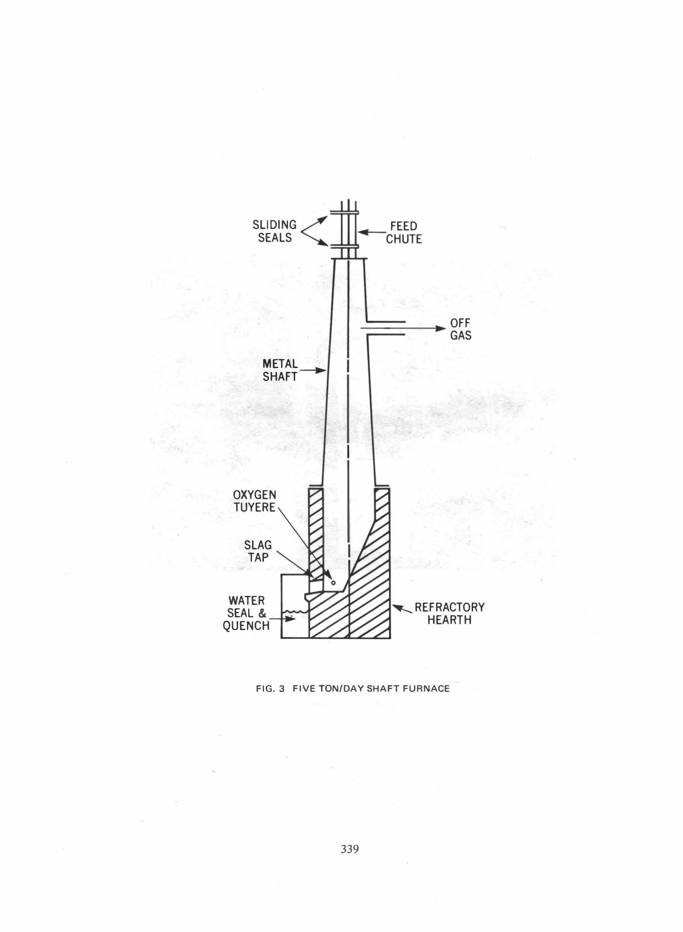
The main emphasis in the experimental program was placed on the development and optimization of the shaft furnace. A drawing is shown in Fig. 3. The bottom section of the furnace constituted a refractory hearth. The hearth was tapered and was sealed on the outside with aluminum plates. Water trickled down the length of the aluminum plates on all four sides keeping the outer surface of the hearth cool. Oxygen was fed through two tuyeres near the bottom of the furnace. There was a single tap for both the molten metal and slag. The molten residue stream flowed into the slag collector where it was quenched in water. The granulated product of metal and glass was manually removed intermittently through a water seal.
SHAFT FURNACE
WATER VAPOR ELECTROSTATIC OFF '--
---... PRECIPITATOR GAS
OXYGEN MOLTON METAL & GLASS
WATER SLAG QUENCH II COLLECTOR
GRANULATED METAL & GLASS
OIL
FLARE
CLEAN CONDENSER FUEL
GAS
WASTE WATER
FIG.2 BLOCK DIAGRAM OF PILOT UNIT
338
•
SLIDING SEALS
METAL ----l ... SHAFT
OXYGEN TUYERE
SLAG TAP
WATER SEAL &_
QUENCH
I
FEED �CHUTE
_ OFF GAS
•
� REFRACTORY HEARTH
FIG. 3 FIVE TON/DAY SHAFT FURNACE
339

FIG.4 PILOT UNIT IN OPERATION
340

The upper protion of the furnace was a tapered metal shaft. The metal shell had no cooling other than the natural convection to the atmosphere. The off gas left the furnace through a duct located below the top of the shaft. Refuse was fed through a chute with two sliding seals to prevent the off gas from escaping during loading.
In Fig. 4 the overall plant is pictured while in operation.
FURNACE OPERATION
The furnace was run at several different operating conditions for extended periods of time (several days). The operating procedures during a test were simple. The oxygen was set at.a predetermined flow rate and was maintained constant. The refuse was fed into the top of the furnace manually using the bed height as an indicator. When the bed height dropped to 3-4 feet, refuse was loaded to bring the height up to about 6-7 feet. There was some bridging of the refuse but it broke up of its own accord without problems. The tapping of the molten metal and glass was continuous requiring no manual action to keep the slag tap open and maintain flow of the molten stream. The oils and waste water were also withdrawn continuously. The flare for the exit fuel gas burned clearly and steadily. The only labor essential for running the pilot plant was that required for loading the refuse into the top of the furnace and for removing the quenched residue from the slag collector. Most of the activity around the unit was associated with the measurements that would be typical of any experimental facility. These activities included recording the gas and water flow rates; checking the temperature readout from probes throughout the system; weighing the refuse input and the metal, slag, water, and oil output; taking samples of gas, water and oil for analyses.
Due to size limitations in the pilot unit, tests could not be made with "as received" real refuse. Experiments were run with both simulated refuse (containing wood, paper, metal, glass, water, and plastic) as well as real refuse reduced in size to permit feeding into the furnace. In a full scale furnace, shredding would not be required.
The rate at which refuse was consumed was constant for any given oxygen flow rate. As noted in the previous paragraph, the refuse was loaded intermittently keeping the bed height between 3 and 7 feet. Each load was weighed and the time recorded when it was fed into the _
furnace. The amount of refuse consumed during a seven hour period at a constant oxygen flow rate is plotted in Fig. 5. As indicated by the straight line drawn thro.ugh the points, the refuse consumption rate was remarkably constant. This was typical of all tests made on the furnace.
341
w en ;:) "-
w a:: en CD ...J
1600r-----------------------------�
1400 f-
1200
1000
800
600
400f-
200 t--
9 10 11 12 AM TIME (HRS)
1 2 PM
3
FIG.5 REFUSE LOADING AT A CONSTANT OXYGEN FLOW RATE
Although there were momentary variations in the combustion and pyrolysis reactions, the time average rates for these reactions were apparently very consistent in consuming the refuse. Rather than depend upon a statistical analysis of fluctuating data, accurate experimental results were obtained for a range of operating conditions such as varying oxygen flow rate and refuse composition.
It is of interest to note how insensitive the furnace operation was to bed height provided a minimum level of 3 feet was maintained. Essentially all of the combustion, pyrolysis and drying occurred in the first three feet of bed height. The temperature at the three foot level was typically about 250°F. This left little sensible heat in the rising gases even for drying. The concentration of pyrolysis and drying steps at the bottom of the furance can be attributed in large part to the high heat transfer rate from the rising combustion products (released by char-oxygen reaction) to the descending refuse. This is characteristic of oxygen-fuel flames which have heat transfer rates an order of magnitude higher than that of comparable air-fuel flames. These results are consistent with the observation that the refuse consumption rate was very constant for extended periods even though the bed height varied between 3 and 7 feet. The insensitivity of the process to refuse bed height simplified the refuse loading, allowing wide variations in the loading procedure. The concentration of the high temperature zone to the bottom few feet of the

furnace also minimized the high temperature corrosion problems.
Oxygen plays an important role in maintaining a high temperature level in the hearth .. At the hearth, the atmosphere is generally reducing as a result of the abundance of fuel, in the form of char, that continually descends into the hearth. On the one hand, the reducing atmosphere is desi,rable since it prevents the oxidation of steel, a potential by-product. On the other hand, however, the heat of combustion is much lower at reducing conditions which would make it difficult to maintain a high hearth temperature. This is illustrated in the following table for the oxidation of char.
Conditions
Reducing
Oxidizing
Reactions
C+Y,O,�CO
C+O,�CO,
Heat of Combustion
BTU/lb carbon BTU/lb oxygen
3,950 14,090
2,960
5,280
The problem of available energy to maintain temperature is not severe when oxygen is' used instead of air as the oxidant. Since there is no nitrogen dilution when using oxygen, the flame temperature is greatly enhanced. For reducing conditions in the hearth, the combustion energy available above 3000°F and the heat transfer rate at 3000°F is two and four times respectively greater using oxygen rather than air even when the air is preheated to 2000°F. Translated into practical terms, this means that the use of oxygen insures reliable operation preventing the solidification of the melt in the hearth for the full range of municipal compositions encountered.
The wear of the hearth is a significant problem in any slagging operation. This can be solved in part by the proper choice of refractories. However, refractories alone cannot solve the problem. In the pilot unit, the hearth was contained in a water-cooled metal shell. This limited the erosion that occurred at the slag line within the hearth where the wear is high. A point was reached where the cooling rate was sufficient to freeze the inner wall of the hearth forming a protective skull composed of molten slag that has solidified. The slag adheres to the surface of the refractory and limits further wear of the refractory.
OXYGEN CONSUMPTION
The oxygen consumption, dermed herein as the tons of oxygen required per ton of refuse consumed, is a significant variable in evaluating the process. A paper study on oxygen furnaces reported in the literature (2) indicated that the oxygen consumption would be high - 0.3 to 0.4 ton oxygen/ton refuse. Such high oxygen consumption is
undesirable because of the cost of pro�ucing the oxygen, the extra heat load on the system and decrease in the heating value of the product gas. One of the most important conclusions that was reached early in this investigation was that the oxygen consumption for a properly designed furnace should be low - about 0.18 to 0.20 ton oxygen/ ton refuse. This conclusion has been confirmed in tests with the pilot plant and in computer studies simulating the operation of shaft furnace.
A simplified line of reasoning is set forth here to elucidate the factors determining oxygen consumption. Oxygen enters the bottom of the furnace and reacts with the descending char in the hearth to release energy of combustion. This energy is required within the shaft furnace to account for the following operations that consume energy:
1) Melting of the inorganic residue (metal, glass and ash). 2) Pyrolysis of the organic portion of the refuse. 3) Vaporization of the moisture in the refuse. 4) Heat loss from the furnace.
The oxygen consumption is determined by the combustion energy it supplies to fulftll the requirements above. As a rough rule of thumb, the energy requirement for the first three operations (melting the residue, pyrolysis of the organic portion and vaporization of the moisture) are about the same on a unit weight basis. That is, the energy requirement of the oxygen converter for processing refuse with an increased amount of glass or moisture, for example, should be about the same per ton of refuse on an "as received" basis. Since the oxygen consumption is directly proportional to the energy requirement, the oxygen consumption should be about the same for these changes in refuse composition. This has been borne out in tests on the pilot unit. This conclusion should hold true for a modestly wide range of refuse compositions. However, very large changes in refuse composition could affect the oxygen consumption.
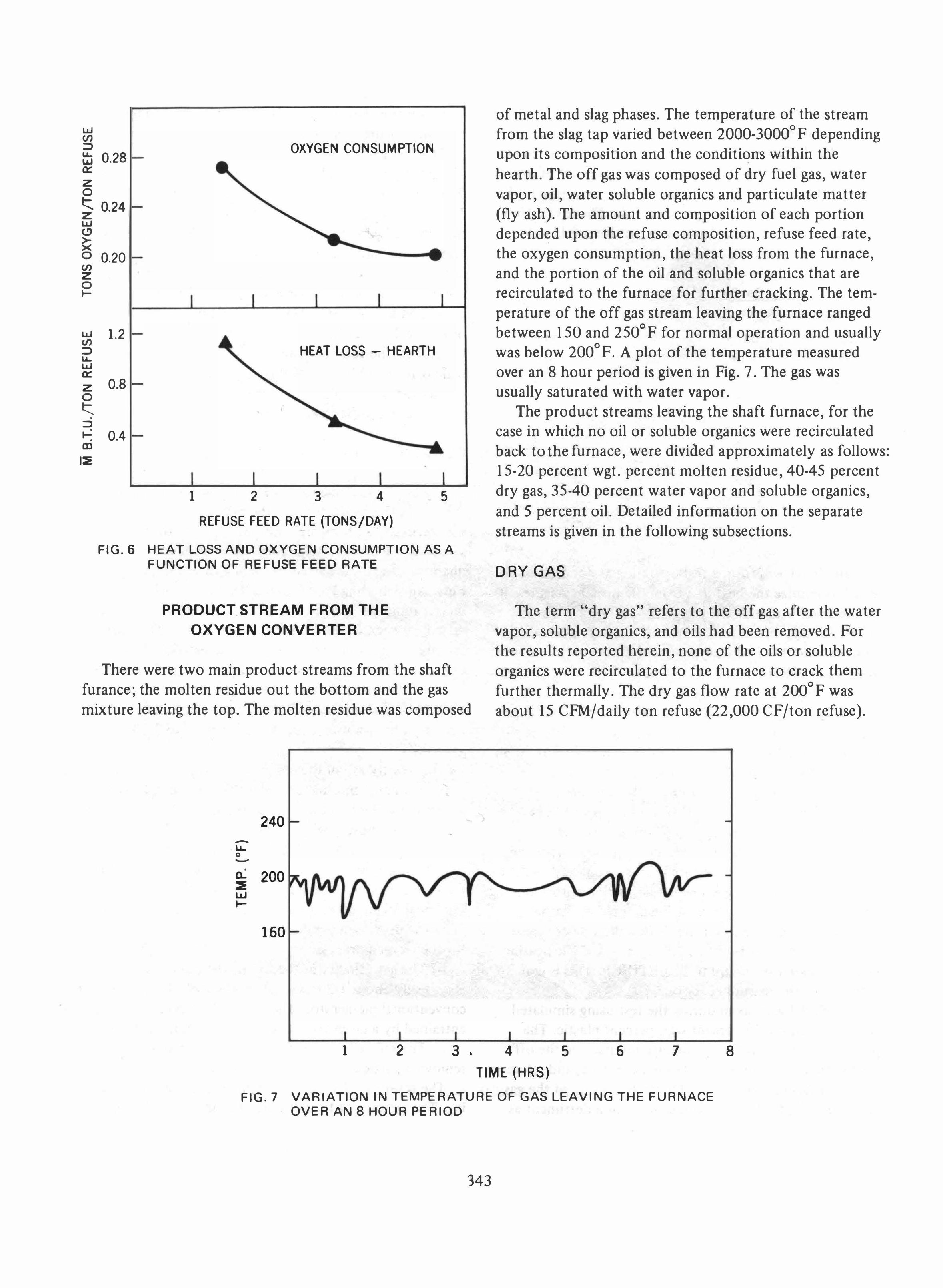
The biggest single factor that can change the oxygen consumption is the heat loss from the furnace. The greater the heat loss from the furnace, the greater the oxygen consumption. This is illustrated in Fig. 6 in which the oxygen consumption and heat loss from the furnace are plotted as a function of the refuse feed rate. The refuse feed rate was varied for these tests by increasing the oxygen flow rate to the tuyeres. As the refuse feed rate increased from 1.5 to 4.9 tons/day, the oxygen consumption decreased from 0.27 to 0.20 tons oxygen/ton refuse and the measured heat loss from the furnace decreased - -from 1.1 M BTU /ton refuse to 0.3 M BTU/ton refuse. These results are in qualitative agreement with the theoretical reasoning.
342
UJ (/) ::> t::i 0.28 0::: z o t:::. 0.24 z UJ <.? � o 0.20 (/) z o t-
UJ (/) 1.2 ::> ..... UJ 0::: z 0.8 0 t:::. • ::> •
0.4 t-• CD
I::E
OXYGEN CONSUMPTION
HEAT LOSS - HEARTH
1 2 3 4 5
REFUSE FEED RATE (TONS/DAY)
of metal and slag phases. The temperature of the stream from the slag tap varied between 2000-3000op depending upon its composition and the conditions within the hearth. The off gas was composed of dry fuel gas, water vapor, oil, water soluble organics and particulate matter (fly ash). The amount and composition of each portion depended upon the refuse composition, refuse feed rate, the oxygen consumption, the heat loss from the furnace, and the portion of the oil and soluble organics that are recirculated to the furnace for further cracking. The temperature of the off gas stream leaving the furnace ranged between 150 and 2500p for normal operation and usually was below 200op. A plot of the temperature measured over an 8 hour period is given in Pig. 7. The gas was usually saturated with water vapor.
The product streams leaving the shaft furnace, for the case in which no oil or soluble organics were recirculated back to the furnace, were divided approximately as follows: 15-20 percent wgt. percent molten residue, 40-45 percent dry gas, 35-40 percent water vapor and soluble organics, and 5 percent oil. Detailed information on the separate streams is given in the following subsections.
FIG.6 HEAT LOSS AND OXYGEN CONSUMPTION AS A FUNCTION OF REFUSE FEED RATE
DRY GAS
PRODUCT STREAM FROM THE
OXYGEN CONVERTER
There were two main product streams from the shaft furance; the molten residue out the bottom and the gas mixture leaving the top. The molten residue was composed
The term "dry gas" refers to the off gas after the water vapor, soluble organics, and oils had been removed. Por the results reported herein, none of the oils or soluble organics were recirculated to the furnace to crack them further thermally. The dry gas flow rate at 2000p was about 15 CPM/daily ton refuse (22,000 CP/ton refuse).
240 -..... 0 �
• Q... 200 :::E UJ to-
160
1 2 3. 4 5
TIME (HRS)
6 7
FIG.7 VARIATION IN TEMPERATURE OF GAS LEAVING THE FURNACE OVER AN 8 HOUR PERIOD
343
8
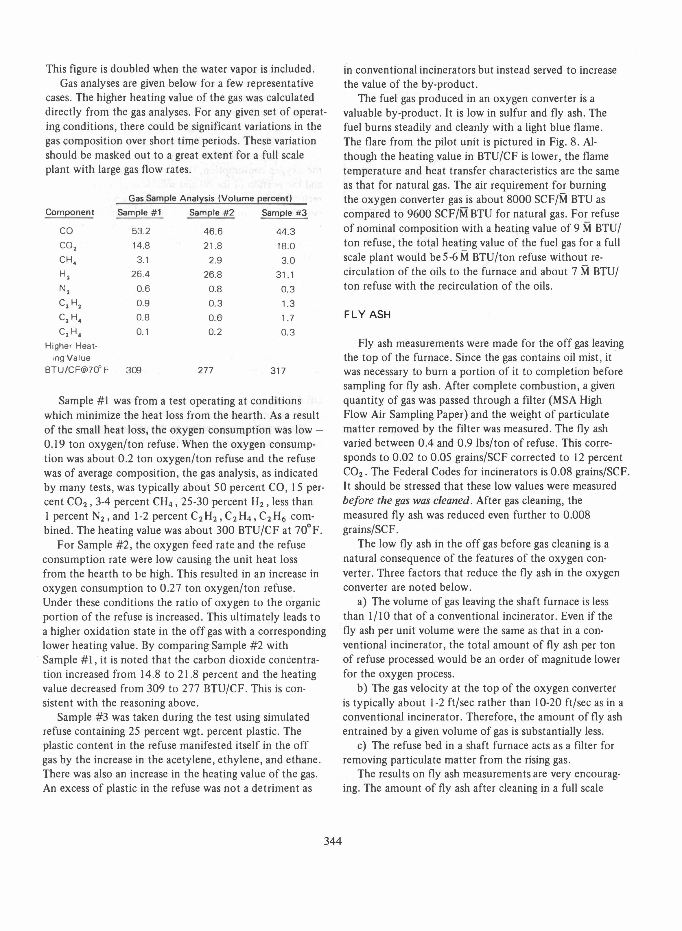
This figure is doubled when the water vapor is included. Gas analyses are given below for a few representative
cases. The higher heating value of the gas was calculated directly from the gas analyses. For any given set of operating conditions, there could be significant variations in the gas composition over short time periods. These variation should be masked out to a great extent for a full scale plant with large gas flow rates.
Gas .Sample Analysis (Volume percent)
Component Sample #1 Sample #2 Sample #3
CO 53.2 46.6 44.3 CO2 14.8 21.8 18.0 CH. 3.1 2.9 3.0 H2 26.4 26.8 31.1
N2 0.6 0.8 0.3 C2 H2 0.9 0.3 1.3 C2 H. 0.8 0.6 1.7 C2H. 0.1 0.2 0.3
Higher Heat-ing Value
BTU/CF@70°F 309 277 317
Sample #1 was from a test operating at conditions which minimize the heat loss from the hearth. As a result of the small heat loss, the oxygen consumption was low -
0.19 ton oxygen/ton refuse. When the oxygen consumption was about 0.2 ton oxygen/ton refuse and the refuse was of average composition, the gas analysis, as indicated by many tests, was typically about 50 percent CO, 15 percent CO2, 3-4 percent CH4, 25-30 percent H2 , less than 1 percent N2 , and 1-2 percent C2 H2, C2 H4, C2 H6 combined. The heating value was about 300 BTU/CF at 70°F.
For Sample #2, the oxygen feed rate and the refuse consumption rate were low causing the unit heat loss from the hearth to be high. This resulted in an increase in oxygen consumption to 0.27 ton oxygen/ton refuse. Under these conditions the ratio of oxygen to the organic portion of the refuse is increased. This ultimately leads to a higher oxidation state in the off gas with a corresponding lower heating value. By comparing-Sample #2 with
. Sample #1, it is noted that the carbon dioxide concentration increased from 14.8 to 21.8 percent and the heating value decreased from 309 to 277 BTU/CF. This is consistent with the reasoning above.
Sample #3 was taken during the test using simulated refuse containing 25 percent wgt. percent plastic. The plastic content in the refuse manifested itself in the off gas by the increase in the acetylene, ethylene, and ethane. There was also an increase in the heating value of the gas. An excess of plastic in the refuse was not a detriment as
344
in conventional incinerators but instead served to increase the value of the by-product.
The fuel gas produced in an oxygen converter is a valuable by-product. It is low in sulfur and fly ash. The fuel burns steadily and cleanly with a light blue flame. Th� flare from the pilot unit is pictured in Fig. 8. Although the heating value in BTU/CF is lower, the flame temperature and heat transfer characteristics are the same as that for natural gas. The air requirement for burning the oxygen converter gas is about 8000 SCF/M BTU as -compared to 9600 SCF /M BTU for natural gas. For refuse of nominal composition with a heating value of 9 M BTU/ ton refuse, the total heating value of the fuel gas for a full -scale plant would be 5 -6 M BTU/ton refuse without re-circulation of the oils to the furnace and about 7 M BTU/ ton refuse with the recirculation of the oils.
FLY ASH
Fly ash measurements were made for the off gas leaving the top of the furnace. Since the gas contains oil mist, it was necessary to burn a portion of it to completion before sampling for fly ash. After complete combustion, a given quantity of gas was passed through a fIlter (MSA High Flow Air Sampling Paper) and the weight of particulate matter removed by the fIlter was measured. The fly ash varied between 0.4 and 0.9 lbs/ton of refuse. This corresponds to 0.02 to 0.05 grains/SCF corrected to 12 percent CO2, The Federal Codes for incinerators is 0.08 grains/SCF. It should be stressed that these low values were measured before the gas was cleaned. After gas cleaning, the measured fly ash was reduced even further to 0.008 grains/SCF.
The low fly ash in the off gas before gas cleaning is a natural consequence of the features of the oxygen converter. Three factors that reduce the fly ash in the oxygen converter are noted below.
a) The volume of gas leaving the shaft furnace is less than 1/10 that of a conventional incinerator. Even if the fly ash per unit volume were the same as that in a conventional incinerator, the total amount of fly ash per ton of refuse processed would be an order of magnitude lower for the oxygen process.
b) The gas velocity at the top of the oxygen converter is typically about 1-2 ft/sec rather than 10-20 ft/sec as in a conventional incinerator. Therefore, the amount of fly ash entrained by a given volume of gas is substantially less.
c) The refuse bed in a shaft furnace acts as a fIlter for removing particulate matter from the rising gas.
The results on fly ash measurements are very encouraging. The amount of fly ash after cleaning in a full scale

FIG. 8 FLARE OF PRODUCT GAS
345

plant should be an order of magnitude lower than the Federal Code.
WATER
The water content in the off gas was high for all tests made on the pilot unit. The amount varied depending upon the refuse composition, especially the moisture content. Typically the water vapor was equal in volume to the dry gas volume in the off gas. The source of water was due in large part to the high percentage of moisture in municipal refuse. There is also an appreciable amount of water given off by the pyrolysis of cellulose (paper, wood and vegetable products) making up the bulk of the organic portion of the refuse. The volume of water removed by the condenser was typically about 80-100 gall ton refuse.
OILS
The oil as obtained from the pilot unit was thick and viscous at room temperature with a specific gravity of about 1.1. Essentially all of its components boiled about 200°F. The ultimate analysis indicated a hydrogen to carbon ratio of less than one. The heating value was about 14,000 BTU/lb oil- essentially the same as pure carbon. Lower heating values were measured but this was accounted for by the entrained water. When the oil was heated to 160-200°F, it poured easily. At this temperature range the oil was easily pumped to a burner and through a nozzle.
The handling of the oil should be straightforward in a full scale plant. The oil will be removed from the off gas stream using an electrostatic precipitator with a minimum entrainment of water. The end use of the oil is optional.
, It could be pumped back to the furnace and cracked to form fuel gas.
,
SLAG AND METAL
The molten slag and metal flowed out of a single tap at the bottom of the hearth. The tapping was continuous with the stream being composed of molten slag most of the time. The molten metal tended to build up under the slag. Every once in awhile there will be a sudden surge of molten metal pouring out the tap. If desired, a second tap could be used for metal to keep it separate from the slag. In Fig. 9 a picture of the slag and metal after quenching is shown.
346
•
•
• •
FIG.9 GRANULATED GLASS & METAL AFTER QUENCHING
Analyses were made of the slag. For tests using refuse from New York tity, a breakdown of the major slag components is as follows:
FeO 8.3 wgt. percent
Fe2O, 1.4 MnO 0.6
Si02 53.0
CaO 11.5
AI2O, 7.7 Ti02 0.1
REFERENCES
[l] J. E. Anderson, U.S. Patent 3,729,298, April 24, 1973.
[2] R. E. Zinn, C. R. LaMantia, and W. R. Niessen, "Total
Incineration", Proceedings of National Incinerator Conference, ASME, Cincinnati, Ohio 1970, pp. 116-127.