the performance pipe engineering manual
TRANSCRIPT
7/23/2019 The Performance Pipe Engineering Manual
http://slidepdf.com/reader/full/the-performance-pipe-engineering-manual 1/208
CPChem
a dia dia dia dia division of vision of vision of vision of vision of CheCheCheCheChevr vr vr vr vr on Phillips Chemical Companon Phillips Chemical Companon Phillips Chemical Companon Phillips Chemical Companon Phillips Chemical Company LPy LPy LPy LPy LP
PERFORMANCE PIPEPERFORMANCE PIPEPERFORMANCE PIPEPERFORMANCE PIPEPERFORMANCE PIPE
TM
©2002 Performance PipeTM
The Performance PipeTM
Engineering Manual
Book 1: Engineering Properties
All rights reserved. This publicaiton is fully protected by copyright and nothing that appears in it may
be reprinted, copied, or otherwise reproduced by any means including electronic media, either wholly
or in part, without the express written permission of Performance PipeTM a division of Chevron Phillips
Chemical Company LP.
NOTICE -- This Manual is intended to be used as a guide to support the designer of polyethylene
piping systems. It is not intended to be used as installation instructions, and should not be substi-
tuted in place of the advice of a professional design engineer. There may be a more current version
of this manual. Contact Performance PipeTM for more informantion.
PLEXCO, PLEXVUE, and YELLOWSTRIPE are registered trademarks of Chevron Phillips
Chemical Company LP in the United States of America; BLUESTRIPE, CP CHEM, DRISCOPLEX,
GREENSTRIPE, PERFORMANCE PIPE, PLEXCO BLUESTRIPE, PLEXSHIELD, PLEXSTRIPE,
PURPLESTRIPE, REDSTRIPE, and SPIROLITE are trademarks of Chevron Phillips Chemical
Company LP in the United States of America.
Return to TOC

7/23/2019 The Performance Pipe Engineering Manual
http://slidepdf.com/reader/full/the-performance-pipe-engineering-manual 2/208
Book 1: Chapter 1: About Performance Pipe page 1 ©2002 Chevron Phillips Chemical Company LP1/21/2002 Supercedes all previous issues
1. About PERFORMANCE PIPE
Performance Pipe1 is the successor to Plexco2 and Driscopipe3. On July 1, 2000, ChevronChemical Company and Phillips Chemical Company joined to form Chevron Phillips ChemicalCompany LP. Performance Pipe, a division of Chevron Phillips Chemical Company LP,succeeds Plexco and Driscopipe as North America’s largest producer of polyethylene pipingproducts for industrial, municipal and utility applications.
Performance Pipe tenders more than forty years of polyethylene piping experience, twelvemanufacturing facilities certified to ISO 9001 in nine states, and two manufacturing facilities inMexico.
Performance Pipe manufactures 1/2" through 54" outside diameter controlled polyethylene pipeand tubing, DRISCOPLEX™ 2000 SPIROLITE™ 18" through 120" inside diameter controlledpolyethylene profile-wall pipe, and molded fittings, fabricated fittings, manholes, tanks, andfabricated structures for domestic and international markets.
The unmatched quality and performance of DRISCOPLEX™ polyethylene piping products isenhanced and strengthened with over four decades of quality polyolefin plastic resin productionfrom Chevron Phillips Chemical Company.
The Polyethylene Pipe Advantage
Performance Pipe polyethylene piping products have unique features that are ideal for manyvaried applications. DRISCOPLEX™ polyethylene pipes have excellent abrasion resistance,superb impact resistance, and extraordinary toughness. The smooth, non-wetting bore offerslow resistance to the flow of water, wastewater, and water borne slurries. DRISCOPLEX™polyethylene pipes are resistant to a broad range of corrosive chemicals, they do not support
biological growth, and they resist the adherence of scale and deposits.
Performance Pipe polyethylene piping products are cost-effective solutions for a broad range of piping applications in gas, water, utility, municipal, industrial, marine, mining, and agriculturalapplications; in installations that are above ground, on the surface, buried, sliplined, trenchless,floating, and submerged. Fluids transported include water, wastewater, slurries, compressedgasses, odorous and corrosive gasses, chemicals, and hazardous wastes.
1 Throughout this manual, “Performance Pipe” refers to Performance Pipe, a division of Chevron Phillips ChemicalCompany LP. “Performance Pipe” followed by a product description (e.g. Performance Pipe polyethylene pipe)denotes products manufactured by Performance Pipe, and when followed by a product description, Performance Pipeis a trademark of Chevron Phillips Chemical Company LP. DRISCOPLEX™ is a trade name of Chevron PhillipsChemical Company LP. SPIROLITE™ is a registered trademark (registration pending) of Chevron Phillips ChemicalCompany LP.
2Plexco was formerly a Division of Chevron Chemical Company.
3Driscopipe was formerly a Division of Phillips Petroleum Company.
Return to TOC
7/23/2019 The Performance Pipe Engineering Manual
http://slidepdf.com/reader/full/the-performance-pipe-engineering-manual 3/208
Book 1: Chapter 1: About Performance Pipe page 2 ©2002 Chevron Phillips Chemical Company LP1/21/2002 Supercedes all previous issues
Some of the features of DRISCOPLEX™ polyethylene piping products include:
Identification Stripes and Colors
Handling
Flexibility and Toughness
Pressure Rating
Service Temperatures
Non-Contaminating
Outstanding Chemical Resistance
Sealed, Leak-Tight Heat Fusion Joints
Excellent Hydraulics
Surge and Liquid Velocity
Abrasion Resistance
Thermal Expansion
Lower Life Cycle Costs
Identification Stripes and Colors
Color-coding has become the preferred way to identify differences among piping services, sizingsystems, and to differentiate multiple DR’s (pressure ratings) on the jobsite. For identificationthat is as permanent as the pipe, many DRISCOPLEX™ products have color stripes extrudedinto the pipe surface. Solid color pipes or a color shell extruded on the outside or inside of thepipe are also available.
Colors to identify applications:
Yellow for natural gas
Blue for potable water
Red for underground fire main
Green for wastewater
Purple for treated effluent
Other stripe colors — white, orange, gray — to meet application requirements
Color stripe patterns to identify sizing systems: IPS (iron pipe) sized pipe — four color stripes equally spaced around the pipe
DIPS (ductile iron) sized pipe — three pairs of color stripes equally spaced around the pipe
Color stripes to identify DR:
Single-striped pipe provides an easy, obvious, quick means to identify the pipe DR (dimensionratio) on a multiple DR project. Each permanent, co-extruded color designates a different DR —
Return to TOC

7/23/2019 The Performance Pipe Engineering Manual
http://slidepdf.com/reader/full/the-performance-pipe-engineering-manual 4/208
Book 1: Chapter 1: About Performance Pipe page 3 ©2002 Chevron Phillips Chemical Company LP1/21/2002 Supercedes all previous issues
which determines pressure rating. Single-striped DRISCOPLEX™ pipe for mining, industrial andmunicipal applications makes installation and inspection more cost effective, and helps ensurethat pipes with the correct pressure rating are installed in their proper location.
Color White Red Yellow Gray Orange Blue Purple Green Pink Brown
DR 7.3 9 11 13.5 15.5 17 21 26 32.5 41
Solid Colors
Solid color pipe, duct and conduit are available. DRISCOPLEX™ 6500 PE 2406 mediumdensity gas pipe is used world wide for gas distribution. DRISCOPLEX™ 4600 andDRISCOPLEX™ 4700 solid gray pipe facilitates video inspection in sewer applications. Redand black electrical conduit, and orange, black, gray, blue and white communications duct areavailable for single or parallel coil installation.
Handling
Made from materials much, much lighter than ductile iron and reinforced concrete, tough,lightweight DRISCOPLEX™ polyethylene pipes do not require the heavy handling and layingequipment commonly required for ductile iron and concrete pipe. Rather than handling short,heavy pipe sections, longer lengths of comparably sized polyethylene pipes typically weigh lessthan a fifth as much. Some smaller sizes can even be carried by hand.
Flexibility and Toughness
Polyethylene pipe is flexible, allowing it to follow rolling terrain contours and reducing the needfor fittings.
Caution — Protect polyethylene piping against excessive bending and shear loads where pipes
emerge from structures such as walls or casings; and at rigid connections such as flanges and mechanical joints.
Protect small pipes at connections to plastic or metal tapping tees or service or branch outlets(protective sleeves should be used).
Protect connections to much larger pipes, tanks, manholes, etc.
During installation, protect fabricated PE fittings against bending.
At a minimum, areas that are subject to bending or shear loads must be carefully installed and properly supported to minimize undue loads that could result in premature failure.
DRISCOPLEX™ polyethylene pipes retain working flexibility even in harsh climates and under adverse conditions. Water within the pipe may freeze solid without damage to the pipe;however, ice blockages must be thawed before pumping is resumed. Unstable soils andseasonal freeze/thaw conditions have little effect on this flexible, elastic piping system.
Polyethylene pipe is becoming the material of choice for directional drilling. It’s flexibility andtoughness facilitate installation and reduces costs.
Return to TOC
7/23/2019 The Performance Pipe Engineering Manual
http://slidepdf.com/reader/full/the-performance-pipe-engineering-manual 5/208
Book 1: Chapter 1: About Performance Pipe page 4 ©2002 Chevron Phillips Chemical Company LP1/21/2002 Supercedes all previous issues
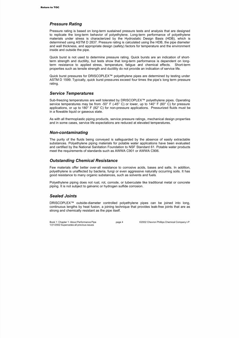
Pressure Rating
Pressure rating is based on long-term sustained pressure tests and analysis that are designedto replicate the long-term behavior of polyethylene. Long-term performance of polyethylenematerials under stress is characterized by the Hydrostatic Design Basis (HDB), which isdetermined using ASTM D 2837. Pressure rating is calculated using the HDB, the pipe diameter
and wall thickness, and appropriate design (safety) factors for temperature and the environmentinside and outside the pipe.
Quick burst is not used to determine pressure rating. Quick bursts are an indication of short-term strength and ductility, but tests show that long-term performance is dependent on long-term resistance to applied stress, temperature, fatigue and chemical effects. Short-termproperties such as tensile strength and ductility do not provide an indication of service life.
Quick burst pressures for DRISCOPLEX™ polyethylene pipes are determined by testing under ASTM D 1599. Typically, quick burst pressures exceed four times the pipe’s long term pressurerating.
Service Temperatures
Sub-freezing temperatures are well tolerated by DRISCOPLEX™ polyethylene pipes. Operatingservice temperatures may be from -50° F (-45° C) or lower, up to 140° F (60° C) for pressureapplications, or up to 180° F (82° C) for non-pressure applications. Pressurized fluids must bein a flowable liquid or gaseous state.
As with all thermoplastic piping products, service pressure ratings, mechanical design propertiesand in some cases, service life expectations are reduced at elevated temperatures.
Non-contaminating
The purity of the fluids being conveyed is safeguarded by the absence of easily extractablesubstances. Polyethylene piping materials for potable water applications have been evaluatedand certified by the National Sanitation Foundation to NSF Standard 61. Potable water productsmeet the requirements of standards such as AWWA C901 or AWWA C906.
Outstanding Chemical Resistance
Few materials offer better over-all resistance to corrosive acids, bases and salts. In addition,polyethylene is unaffected by bacteria, fungi or even aggressive naturally occurring soils. It hasgood resistance to many organic substances, such as solvents and fuels.
Polyethylene piping does not rust, rot, corrode, or tuberculate like traditional metal or concretepiping. It is not subject to galvanic or hydrogen sulfide corrosion.
Sealed Joints
DRISCOPLEX™ outside-diameter controlled polyethylene pipes can be joined into long,continuous lengths by heat fusion, a joining technique that provides leak-free joints that are asstrong and chemically resistant as the pipe itself.
Return to TOC
7/23/2019 The Performance Pipe Engineering Manual
http://slidepdf.com/reader/full/the-performance-pipe-engineering-manual 6/208
Book 1: Chapter 1: About Performance Pipe page 5 ©2002 Chevron Phillips Chemical Company LP1/21/2002 Supercedes all previous issues
Inside-diameter controlled DRISCOPLEX™ 2000 SPIROLITE™ pipes are joined using push-ontype, gasketed-spigot-and-bell joints. The DRISCOPLEX™ 2000 SPIROLITE™ joint meets or exceeds ASTM D 3212 deflected joint leak tightness requirements.
Excellent Hydraulics
Polyethylene pipe behaves as an “ideally smooth conduit,” offering extremely low resistance tothe flow of fluids. Superior chemical resistance and a non-wetting (wax-like) surface combine tovirtually eliminate scaling and pitting, and to preserve excellent hydraulic characteristicsthroughout the pipe’s service life.
Surge and Liquid Velocity
Unlike traditional piping which may require a working pressure reduction to cope with surgeevents, DRISCOPLEX™ polyethylene pipe is resilient, and can withstand surge-inducedpressures that exceed the pipe’s pressure rating (pressure class). When joined using properlymade butt fusion joints, fully restrained mechanical connections, and flanged connections, the
allowable water hammer surge pressure may be up to 50% above the pipe pressure rating(pressure class) when surges are frequent, or up to 100% above the pipe pressure rating(pressure class) when surges are infrequent. Surge pressure allowance may be restricted whenthere are many fittings, and where other appurtenances such as valves or hydrants limit surgepressures. Because polyethylene is resilient and has a lower elastic modulus, surge pressuresin polyethylene pipe are 80% lower than in ductile iron, and 50% less than in PVC.
Acceptable fluid flow velocity is dependent on the application and on system design. For example, pressure water system flow velocities as high as 14 fps may be acceptable whereuncontrolled surge is infrequent, and where surge pressures are controlled, velocities higher than 20 fps may be acceptable.
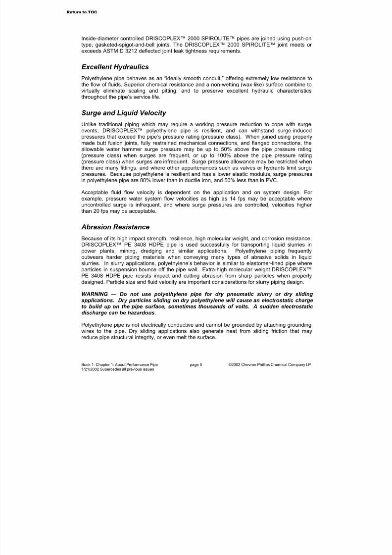
Abrasion Resistance
Because of its high impact strength, resilience, high molecular weight, and corrosion resistance,DRISCOPLEX™ PE 3408 HDPE pipe is used successfully for transporting liquid slurries inpower plants, mining, dredging and similar applications. Polyethylene piping frequentlyoutwears harder piping materials when conveying many types of abrasive solids in liquidslurries. In slurry applications, polyethylene’s behavior is similar to elastomer-lined pipe whereparticles in suspension bounce off the pipe wall. Extra-high molecular weight DRISCOPLEX™PE 3408 HDPE pipe resists impact and cutting abrasion from sharp particles when properlydesigned. Particle size and fluid velocity are important considerations for slurry piping design.
WARNING — Do not use polyethylene pipe for dry pneumatic slurry or dry sliding
applications. Dry particles sliding on dry polyethylene will cause an electrostatic chargeto build up on the pipe surface, sometimes thousands of volts. A sudden electrostatic discharge can be hazardous.
Polyethylene pipe is not electrically conductive and cannot be grounded by attaching groundingwires to the pipe. Dry sliding applications also generate heat from sliding friction that mayreduce pipe structural integrity, or even melt the surface.
Return to TOC
7/23/2019 The Performance Pipe Engineering Manual
http://slidepdf.com/reader/full/the-performance-pipe-engineering-manual 7/208
Book 1: Chapter 1: About Performance Pipe page 6 ©2002 Chevron Phillips Chemical Company LP1/21/2002 Supercedes all previous issues
Thermal Expansion
Non-buried pipelines, such as surface or suspended pipelines, or pipelines within above gradecasings, will expand or contract in diameter and length with changing temperature. Anapproximate length change allowance is “one – ten – one-hundred”, that is about 1" for a 10° Ftemperature change for each 100’ of pipe.
System designs should accommodate thermal length change effects when they apply. Thermalexpansion and contraction length change can be much greater compared to non-PE pipingsystems, but loads on anchors and supports are usually much lower. Hanging the pipe fromsupports that allow lateral movement, expansion loops, snaking the pipe in the right-of-way, andvarious anchoring techniques may be employed. Expansion joints should not be considered unless they are designed specifically for PE pipe.
Additional Information
For additional information on use, design and installation considerations, see the PerformancePipe Engineering Manual Book 2: System Design and the Performance Pipe Engineering Manual Book 3: System Installation.
Go to Chapter 2
Return to TOC
7/23/2019 The Performance Pipe Engineering Manual
http://slidepdf.com/reader/full/the-performance-pipe-engineering-manual 8/208
Book 1: Chapter 2: Performance Pipe Products page 7 ©2002 Chevron Phillips Chemical Company LP1/12/2002 Supercedes all previous issues
2. Performance Pipe ProductsPerformance Pipe polyethylene pipe, fittings, and fabrications are manufactured usingstate-of-the-art pipe extrusion, injection molding, and fabrication processes.DRISCOPLEX™ 2000 SPIROLITE™ pipe, fittings and fabrications are manufactured
using proprietary technology for large, inside diameter controlled polyethylene piping,and state-of-the-art fabrication processes. Performance Pipe products aremanufactured to meet or exceed industry standards for polyethylene piping.
Piping Constructions
Conventionally extruded DRISCOPLEX™ polyethylene pipe in 3" and larger sizes areproduced in standard 40’ or 50’ straight lengths. Longer lengths are available, but arelimited by commercial carrier trailer lengths. Longer lengths reduce the number of joints,and speed installation.
Polyethylene pipe in 6” and smaller sizes is available in coils. Coil dimensions and pipe
length are dependent on diameter and DR (dimension ratio). For 2" and smaller sizes,coils are standard.
Special handling and laying equipment may be required for coiled pipe. Duringinstallation, 4" through 6" coiled pipe may require field processing through re-roundingand straightening equipment.
DRISCOPLEX™ 2000 SPIROLITE™ pipe is inside diameter controlled, and producedin 20’ standard laying lengths. Thirteen-foot lengths are available upon request. Push-on type, gasketed-spigot-and-bell joints are standard.
For information about Performance Pipe polyethylene pipe products, striping, colors,and for custom products such as special outside diameters, extra heavy or extra thinwalls, special wall profiles, and custom fabrications, contact your Performance PipeDistributor or Performance Pipe Territory Manager.
Sizing Systems
Performance Pipe manufactures polyethylene pipe and fittings to meet or exceedapplicable industry standards. Several sizing systems are used:
CTS: Copper Tube Size — same OD as inch-sized copper tubing
IPS: Iron Pipe Size — same OD as inch-sized iron and steel pipe
DIPS: Ductile Iron Pipe Size — same OD as inch-sized ductile iron pipe
Custom OD Sizes — Inch or metric OD sizes per customer specification
ID Controlled — DRISCOPLEX™ 2000 SPIROLITE™ ID Sizes per ASTM F 894;Conventionally extruded ID-controlled Sizes per ASTM D 2239 and AWWA C901
Third Party Certification and Listing
Some DRISCOPLEX™ products are third party certified or listed:
Return to TOC
7/23/2019 The Performance Pipe Engineering Manual
http://slidepdf.com/reader/full/the-performance-pipe-engineering-manual 9/208
Book 1: Chapter 2: Performance Pipe Products page 8 ©2001 Chevron Phillips Chemical Company LP4/11/2002 Supercedes all previous issues
CSA — Canadian Standards Association
FMR — Factory Mutual Research
NSF — National Sanitation Foundation
IAPMO — International Association of Plumbing and Mechanical Officials (marked
with Unified Plumbing Code (UPC) Shield)
RUS — Rural Utility Service listed
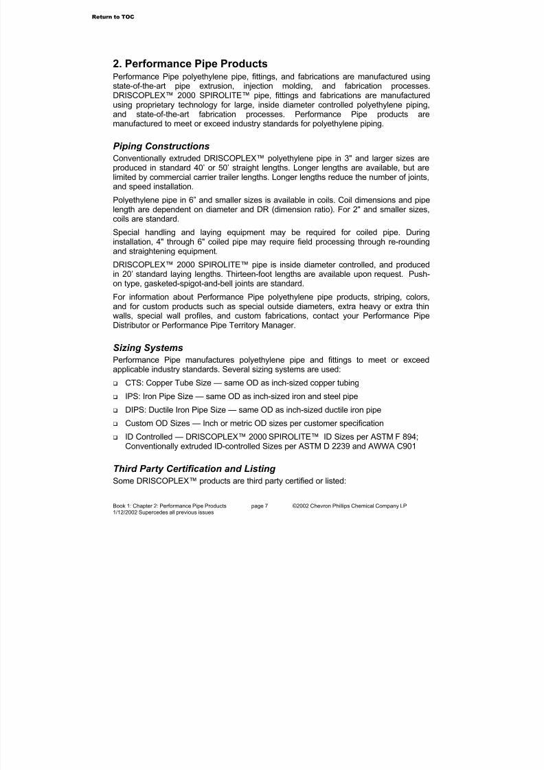
Table 2-1 Performance Pipe DRISCOPLEX™ Products
Previous DesignationsTypical Markets for Pipe and Fittings
Performance PipeDRISCOPLEX™
Series
TypicalFeatures Former Plexco Product
Former DriscopipeProduct
DRISCOPLEX 1000 1, 22 EHMW 1000Municipal, Industrial
DRISCOPLEX 8700 1, 19 EHMW 8700
1, 2, 8, 12 REDSTRIPE™ FM 1000 FM
DRISCOPLEX 1500 1, 2, 8, 23 BLUESTRIPE™-FM –
5, 6, 12, 32 – –
FMR Approved Underground Fire
MainDRISCOPLEX 1600
5, 6, 23, 32 – –
Mining DRISCOPLEX 1700 1, 3 PLEXSTRIPE™ 1000 SP
Perforated Pipe DRISCOPLEX 1900 1, 4 EHMW Perforated Pipe –
Water Distribution DRISCOPLEX 4000 5, 6, 7 BLUESTRIPE™ (DIPS) 4000 BLUESHELL (DIPS)
Industrial, Water Distribution, Process
DRISCOPLEX 4100 1, 8, 33, 34 BLUESTRIPE™ (IPS) 4100 BLUESHELL (IPS)
Water Service Pipe& Tubing
DRISCOPLEX 5100 9, 19 BLUESTRIPE™ 5100 ULTRA-LINE®
DRISCOPLEX 4200 8, 10 GREENSTRIPE™ (IPS) 4200 GREENSHELL (IPS)
DRISCOPLEX 4300 5, 6, 10GREENSTRIPE™
(DIPS)4300 GREENSHELL
(DIPS)Sanitary Sewer
DRISCOPLEX 2000SPIROLITE™
11 SPIROLITE™ –
DRISCOPLEX 4400 8, 13 PURPLESTRIPE™ (IPS)4400 LAVENDERSHELL
(IPS)Treated/Reclaimed Water
DRISCOPLEX 4500 5, 6, 13PURPLESTRIPE™
(DIPS)4500 LAVENDERSHELL
(DIPS)
DRISCOPLEX 4600 1, 14 PLEXVUE® (IPS) –
DRISCOPLEX 4700 5, 6, 14, 20 PLEXVUE® (DIPS) –
DRISCOPLEX 1200 1, 15 – 1200 OPTICORE (IPS)Sliplining
DRISCOPLEX 1400 5, 15 – 1400 OPTICORE (DIPS)
Irrigation DRISCOPLEX 4800 16 MDPE –
Dual Containment DRISCOPLEX 2400 1, 17 DCS –
Liner Pipe DRISCOPLEX 9200 18 EHMW 9200
Return to TOC

7/23/2019 The Performance Pipe Engineering Manual
http://slidepdf.com/reader/full/the-performance-pipe-engineering-manual 10/208
Book 1: Chapter 2: Performance Pipe Products page 9 ©2001 Chevron Phillips Chemical Company LP4/11/2002 Supercedes all previous issues
Previous DesignationsTypical Markets for Pipe and Fittings
Performance PipeDRISCOPLEX™
Series
TypicalFeatures Former Plexco Product
Former DriscopipeProduct
Manholes,Structures, Tanks
DRISCOPLEX 2000 21Manholes, Structures,
Tanks –
DRISCOPLEX 6500 1, 24 Yellowpipe® 6500
DRISCOPLEX 6800 1, 25 Plexstripe II 6800
DRISCOPLEX 8100 1, 26 – 8100
DRISCOPLEX 8300 1, 27 Yellowstripe® –
Gas Distribution
DRISCOPLEX 6600 31 Plexshield™ –
Oil Patch-GasGathering
DRISCOPLEX 6400 1, 28 Oil & Gas Pipe 6400
Geothermal DRISCOPLEX 5300 1 Plexco EHMW 5300
DRISCOPLEX 3100 1, 29 Redstripe™ & Redpipe 3100Duct/Conduit
DRISCOPLEX 3200 1, 30 Plexstripe 3200
NOTICE. Capabilities vary from manufacturing plant to manufacturing plant. Contact Performance Pipe todetermine the availability of specific products and the availability of particular stripe or shell colors, striping patterns,and IPS or DIPS sizing.
Legend for Typical Features:
1. IPS sizing system.
2. FMR Approved Class 150 or Class200 in 2” – 24” IPS pipe sizes.
3. A single longitudinal color stripe isextruded into the pipe OD to identifyDR.
4. Various perforation patterns are
available.
5. DIPS sizing system.
6. The DIPS longitudinal color stripepattern is three equally spaced pairsof color stripes extruded into thepipe OD.
7. Blue color stripes are standard. Ablue color shell is available onspecial order.
8. The IPS longitudinal color stripepattern is four equally spaced singlecolor stripes extruded into the pipeOD.
9. NSF Approved. CTS, IPS, andSIDR in 1/2” – 2” sizes.
10. Green color stripes are standard. Agreen color shell is available onspecial order.
11. RSC 40-160 in 18” – 120” ID sizes inopen or closed profile.
12. Red color stripes are standard.
13. Purple color stripes are standard. Alavender color shell is available onspecial order.
14. Solid light gray color.
15. Light gray color lining extruded intopipe ID.
16. Black PE 2406 material.
17. Factory assembled casing andcarrier.
18. Custom wall thickness anddiameters available on special order.
19. PE 3408/PE100 material.
20. Green color stripes are standard.
21. Manholes, tanks and specialstructures made from DRISCOPLEX2000 SPIROLITE™ ® andDRISCOPLEX™ PE 3408 piping
products.
22. 1-1/2” IPS and smaller sizes only.
23. Dual certified FMR & NSF. Bluecolor stripes standard.
24. Yellow PE 2406. IAPMO (UPC)certification for yard gas available.
25. Black PE 3408 with three equallyspaced pairs of longitudinal yellowstripes extruded into the pipe OD.
26. Premium PE 3408/PE 100 HDPE.Yellow color shell.
27. Premium PE 3408/PE 100 HDPE.Four equally spaced longitudinalyellow stripes extruded into the pipe
OD.
28. Made per API 15LE. Not for gasdistribution.
29. Electric duct-conduit. Three equallyspaced, longitudinal red stripesextruded into the pipe OD.
30. Communications duct-conduit.Single longitudinal color stripeavailable.
31. Gas distribution service tubing withina rodent resistant corrugated tube.
32. FMR Approved Class 150 or Class200 in 4” – 24” DIPS pipe sizes.
33. Blue color stripes or blue color shellavailable on special order.
34. 2” IPS and 3” IPS made to ASTM D3035, AWWA C901 and NSF 61. 4”IPS and larger made to ASTM F714, AWWA C906 and NSF 61.
Return to TOC

7/23/2019 The Performance Pipe Engineering Manual
http://slidepdf.com/reader/full/the-performance-pipe-engineering-manual 11/208
Book 1: Chapter 2: Performance Pipe Products page 10 ©2001 Chevron Phillips Chemical Company LP4/11/2002 Supercedes all previous issues
Table 2-2 Markets and Typical Applications and Uses for Performance Pipe M & I Piping Products
Market Typical Applications and Uses
Industrial and Municipal
Industrial Process Piping – Dredging, Slurry and Flyash Lines – Road Drainage andCulverts – Temporary Bypass Pumping – River, Lake and Reservoir Crossings –Force Mains – Odor Control – Sludge Lines – Outfalls and Diffusers – Chemical
Mineral Extraction – Chemical and Corrosive Wastes – Leachate Control Systems –Fabricated Fittings and Custom Fabrications – Manholes, Tanks, Structures, CatchBasins – Impoundment Piping – Pipeline Rehabilitation – Chemical and ZebraMussel Treatment Systems – Snow Making Systems – Subsurface Snow MeltingSystems
FMR Approved Underground Fire Main
Underground Municipal and Industrial Fire Water Systems
Mining Acid Mine Drainage – Chemical Mineral Extraction – Process Pipe and Fittings –Decant Systems – Slurry and Tailings Lines – Dewatering – Impoundment Piping
Perforated Pipe Aeration Systems – Landfill Gas Collection – Leachate Collection – Drainage andWaste Disposal Absorption Fields – Odor Control
Water DistributionUnderground Potable Water Distribution Mains – River, Lake and Reservoir
Crossings – Intake Piping – Directional Drilling – Potable Water Fire MainWater Service Tubing Small Diameter Underground Potable Water Distribution Service Lines
Sanitary Sewer Gravity Sanitary Sewer Mains – Sanitary Sewer Forced Mains – Odor Control –Temporary Bypass Pumping – Dewatering – Storm Drains – Directional Drilling –Chipper Systems
Treated/Reclaimed Water Raw Water Systems – Outfalls and Diffusers
Sliplining Pipeline Rehabilitation – Pipe Bursting – Sliplining
IrrigationHard-Hose Reel Irrigation – Drag-Line Irrigation – Underground Irrigation Water Supply Mains
Dual Containment Chemicals and Corrosive Wastes – Pressure and Gravity Flow Chemical ProcessPiping – Fuel Piping – Purity Assurance (Contamination Prevention) Piping Systems
Liner Pipe Pipeline Rehabilitation – Tight-Fitting Liners – Casing for Insulated Pipe
Manholes, Tanks, StructuresMunicipal Sanitary Sewers – Industrial Sewers – Landfill Leachate Control Systems
– Chemicals and Corrosive Wastes – Storm Drain Systems – Odor Control
Gas DistributionUnderground Utility Gas Distribution – Yard Gas – Insertion Renewal – UndergroundPropane & LPG Distribution
Oilfield & Gas Gathering Brine – CO2 – SO4 – Crude Oil – Wet Gas – Condensate Return Lines
Geothermal Ground Source Heat Pumps – Downhole Geothermal Loop Systems – HorizontalClosed Loop Systems – Subsurface Snow Melting Systems
Conduit-Duct Electric Duct & Casing – Communications Duct & Casing – Directional Drilling
Go to Chapter 3
Return to TOC

7/23/2019 The Performance Pipe Engineering Manual
http://slidepdf.com/reader/full/the-performance-pipe-engineering-manual 12/208
Book 1: Chapter 3: Polyethylene Material Fundamentals page 11 ©2002 Chevron Phillips Chemical Company LP1/12/2002 Supercedes all previous issues
3. Polyethylene Material FundamentalsFrom the 1941 discovery of low-density polyethylene, through the first production in 1957 of high-density polyethylene using a low-pressure process, polyethylene has developed into adiverse family of materials for packaging, wire and cable jacketing, piping and other
applications. Each use demands dedicated polymer engineering to obtain the balance of properties necessary for the application.
Polyethylene materials are engineered for the requirements of the application. Packagingmaterials are engineered for easy processing, but not for long-term stress. Wire and cablematerials are engineered for high electrical and thermal properties. Piping materials mustwithstand decades of stress and strain from internal pressure, earthloads, and other adverseenvironmental conditions.
Both short term and long term physical property tests are used to characterize how an“engineered-for-application” polyethylene material may be expected to perform in use. For temporary-use applications like packaging, short-term tests are usually sufficient, but for demanding, long-term applications such as pipe, tests that accurately evaluate long-term
property characteristics are essential.
PolymerizationTo a large degree, the molecular structure of polyethylene determines its suitability as a pipingmaterial. Polyethylene is made by the polymerization of the ethylene monomer, generally withthe addition of another alpha-olefin co-monomer such as propylene, butene, hexene, etc. For piping applications, thousands of monomeric units are combined to form polyethylene.
If the ethylene monomer were used exclusively, you would “grow” a very linear polyethylenehomopolymer. However, as higher alpha-olefin co-monomers are introduced, the monomer chain lengthens by their inclusion, and short chain or side chain branching occurs. Overallhowever, co-polymer polyethylene is still considered a linear polymer. See Figure 3-1.
Co-polymer polyethylene materials used for piping are prepared by the polymerization of no lessthan 85% ethylene, and no less than 95% of total olefins (up to 10% higher alpha-olefin co-monomers) with additional compoundingingredients.
The polymerization reaction process utilizeshighly sophisticated catalyst systems that initiatepolymerization and propagate the reaction. Resinmanufacturers utilize proprietary catalysttechnology and specialized reaction processes tocontrol polymer processing. Polymers areengineered for various end uses with catalysts,
and combinations of monomer and co-monomer units. Key control indicators for the polymerizationprocess are density, and melt flow rates atseveral conditions.
Fundamental CharacteristicsIn the broadest sense, polyethylene resinproperties are determined largely by three
Figure 3-1 Branched Polyethylene
Molecule
Return to TOC
7/23/2019 The Performance Pipe Engineering Manual
http://slidepdf.com/reader/full/the-performance-pipe-engineering-manual 13/208
Book 1: Chapter 3: Polyethylene Material Fundamentals page 12 ©2002 Chevron Phillips Chemical Company LP1/12/2002 Supercedes all previous issues
fundamental characteristics: crystallinity (density), molecular weight, and molecular weightdistribution.
Crystallinity (Density)
In the solid phase, polyethylene is characterized as a semi-crystalline polymer, that is, it has
both crystalline and amorphous regions. Crystalline regions are dense, ordered regions wherethe molecules are in a regular, ordered structure. Amorphous regions are less dense areas of irregular, random molecular entanglement.
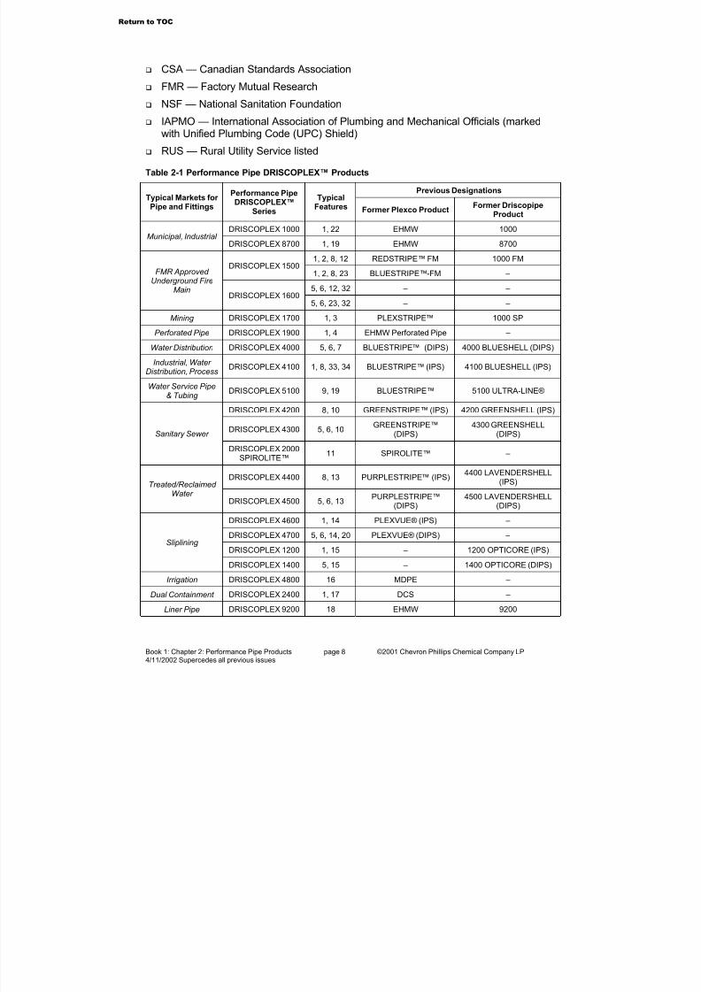
As molten polyethylene cools, nuclei form,and spherulitic crystals of folded moleculechains begin to grow. When a side chainbranch is reached, the branch may beaccommodated within the fold, or it maydisrupt crystal formation and end up in theamorphous region surrounding the crystal,or it may cross over into another crystalline structure. See Figure 3-2.
The density of solid polyethylene resin isdependent upon the rate of cooling fromthe molten state. Quickly quenchedmaterials have lower density becausecrystalline structure has had less time toform and grow. Slow cooling from the meltphase allows more time for crystallization,so density is higher. Heavily branchedmaterials have lower density becausebranching disrupts the crystallization process. Standardized tests that use a specified coolingprocedure are used to determine resin density. When polyethylene is re-melted then re-
solidified, the density of the re-solidified material may vary from the original resin density if thecooling rate is different.
Medium density polyethylene pipe resins typically have average base (unpigmented) resindensities from 0.937 gm/cm3 to 0.940 gm/cm3. High-density pipe resins have densities of 0.941gm/cm3 and above.
Pigmentation Effects on Density
Pigments and other additives are compounded into polyethylene pipe resins for variousreasons; however, these ingredients are a very small percentage of the overall pipe compound.When pigments are compounded into the base resin, the overall density may increase slightly.However, the physical properties of the pigmented compound are set predominantly by the
physical properties of the base resin.
Pigmentation may be a color, or inert ingredients such as titanium dioxide or carbon black. Inthe case of carbon black, density is increased by 0.0044 gm/cm3 per percent carbon. For example, a 0.945 gm/cm3 high-density base resin that is compounded with 2.5% carbon blackwill have a pigmented density of 0.956 gm/cm3. Although the carbon black has increased theoverall density of the compound, the physical properties are still those of the 0.945 gm/cm3 baseresin. ASTM D 1505 is a standard for resin density measurement.
Figure 3-2 Crystalline and Amorphous
Structure
Return to TOC
7/23/2019 The Performance Pipe Engineering Manual
http://slidepdf.com/reader/full/the-performance-pipe-engineering-manual 14/208
Book 1: Chapter 3: Polyethylene Material Fundamentals page 13 ©2002 Chevron Phillips Chemical Company LP1/12/2002 Supercedes all previous issues
Molecular Weight
When polymerized, the polyethylene molecule is a linear chain of carbon-carbon single bonds,flanked by hydrogen. See Figure 3-1. The numbers of monomer and comonomer units joinedtogether determine molecular weight in the polyethylene molecule. The molecular weight of each “mer” unit, C2H2, is 26, so a polyethylene molecule with an average molecular weight of
260,000 has 10,000 mer units in the molecule chain. Analytical methods that directly determine molecular weight include solution viscosity, sizeexclusion chromatography (SEC), and gel permeation chromatography (GPC). Thesesophisticated procedures usually involve running a molten resin solution through a series of columns to determine molecular weight.
In the melt state, higher molecular weight materials usually flow less readily than lower molecular weight materials; thus, melt flow rate may provide an indirect reference — not a direct measure — of molecular weight. Melt flow rate is significantly affected by the polymerizationprocess, by catalyst technology, by side chain branching, by co-polymer material, and bymolecular weight distribution. Among different polyethylenes, it is incorrect to infer performancerelationships on the basis of melt flow rate.
Melt flow rate is used to compare a sample of a material against specifications for that samematerial. Melt flow rate is determined using ASTM D 1238. Under set temperature and loadconditions, the mass of material extruded through a calibrated orifice in a set time is the meltflow rate of the material.
Per ASTM D 1238, polyethylene melt flow rate is usually tested at 190° C, and under loads of 2.16 kg (melt index, MI), and 21.6 kg (high load melt index, HLMI). Loads of 5 kg, 10 kg, and 15kg are also used.
Many properties improve with increasing molecular weight; however the processability of themelted material decreases with increasing molecular weight. Melt processing is important for polyethylene piping materials in extrusion and molding, and in heat fusion joining. Successfulmedium density and high-density polyethylene piping materials generally have MI’s in the range
of 0.04 to 0.20 gm/10 min.
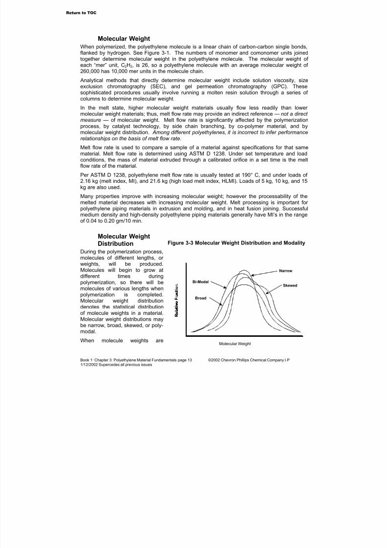
Molecular WeightDistribution
During the polymerization process,molecules of different lengths, or weights, will be produced.Molecules will begin to grow atdifferent times duringpolymerization, so there will bemolecules of various lengths when
polymerization is completed.Molecular weight distributiondenotes the statistical distributionof molecule weights in a material.Molecular weight distributions maybe narrow, broad, skewed, or poly-modal.
When molecule weights are
Figure 3-3 Molecular Weight Distribution and Modality
Molecular Weight
Broad
Bi-ModalSkewed
Narrow
Return to TOC
7/23/2019 The Performance Pipe Engineering Manual
http://slidepdf.com/reader/full/the-performance-pipe-engineering-manual 15/208
Book 1: Chapter 3: Polyethylene Material Fundamentals page 14 ©2002 Chevron Phillips Chemical Company LP1/12/2002 Supercedes all previous issues
closely grouped around a common (average) molecule weight, the distribution is termed narrow. A greater dispersion of weights around the average is indicates a broader distribution. Askewed distribution is an unequal distribution of heavier or lighter molecules to either side of theaverage. See Figure 3-3.
Modality is an indication that there is more than one concentration of molecular weights in the
distribution. Materials with two concentrations are bi-modal, and those with multipleconcentrations are multi-modal or poly-modal.
The polymerization process and the catalysts used determine molecular weight distribution.Different polymerization processes and catalysts will produce materials with different melt flowrates, different distributions, and different physical property values. Different materials may havethe same average molecular weights, but very different molecular weight distributions.
Between polyethylene materials of like molecular weight, the broad molecular weight distributionmaterial will have a higher melt flow rate compared to the same material with narrow molecular weight distribution.
Understanding Property-Characteristic InterrelationshipsPolyethylene piping is specially engineered for piping applications. Reviewing how changes incrystallinity, molecular weight, and molecular weight distribution affect material physicalproperties can provide a general understanding of how polyethylene piping materials areengineered to provide the necessary balance of strength, toughness, and long-termperformance.
A Discussion of Table 3-1
Table 3-1 illustrates show some general interrelationships among the fundamentalcharacteristics of polyethylene and the typical effect on physical properties when a fundamentalcharacteristic is changed. Table 3-1 assumes a single, basic polyethylene material having agiven crystallinity, molecular weight, and molecular weight distribution. The columns below the
fundamental property indicate the relative effect (increase, decrease, or no change) on thephysical property when the fundamental property is changed as indicated.
The effects of change are indicated across the rows from left to right, that is, take the basematerial, and increase its density; take the increased density material and increase its molecular weight; and then take that same material and broaden its molecular weight distribution.
Table 3-1 illustrates that when density is increased, stiffness, hardness, tensile strength andchemical resistance all increase. Increases in these properties are usually considered beneficialfor pipe, but increasing density also has a downside. By increasing density, the materialbecomes less ductile, more sensitive to impact, and more sensitive to cracking under long termstress — generally things that are not so good for pipe.
In the next column, the molecular weight of the higher density material is increased. This offsetssome of the negatives that came along with increased density. Impact strength, low temperaturetoughness, and resistance to cracking from long term stress are all improved by increasingmolecular weight. The downside of increased molecular weight is reduced melt processability(melt flow rate), which is important in product manufacture and in heat fusion joining.
Melt processability is improved by broadening the molecular weight distribution. Resistance toslow crack growth — that is, long-term performance — is also improved.
Table 3-1 generally illustrates that successful polyethylene piping materials are the result of an
Return to TOC
7/23/2019 The Performance Pipe Engineering Manual
http://slidepdf.com/reader/full/the-performance-pipe-engineering-manual 16/208
Book 1: Chapter 3: Polyethylene Material Fundamentals page 15 ©2002 Chevron Phillips Chemical Company LP1/12/2002 Supercedes all previous issues
engineered balance of density, molecular weight, and molecular weight distribution so thatstrength, toughness, long-term performance, and the ability to manufacture, join, and install areoptimized.
Table 3-1 is intended only as a general illustration of influences and interrelationships. Somepolyethylene materials may have interactions among properties and characteristics that may
deviate significantly from the Table 3-1 illustration.In particular, different polymerization reaction processes, catalysts, and co-monomers willproduce different polymers. Polyethylene made using one polymerization process, or set of catalysts, or co-monomer should not be directly compared to materials made using differentprocesses, catalysts, or co-monomers. Polymerization processes and catalyst technologies canimpart distinctive characteristics to the material that may enhance or diminish a property or characteristic, and how it interacts with another. Table 3-1 does not address the possible effectsof different polymerization processes, catalyst technologies, or co-monomers on materials.
Table 3-1 Physical Property Changes due to Fundamental Characteristic Changes
Fundamental Characteristic (change)
Material Property Crystallinity (increase)
Molecular Weight
(increase)
Molecular Weight
Distribution (broaden)
Stiffness Increases – –
Tensile Strength at Yield Increases – –
Tensile Strength at Break Increases Increases, then levels off –
Tensile Elongation at Break (Ductility)
Decreases – –
Softening Temperature Increases Increases Increases
Impact Strength Decreases Increases, then levels off –
Low TemperatureToughness
Decreases Increases Increases
Permeation Resistance Increases – –
Chemical Resistance Increases – –
Resistance to Slow Crack Growth
Decreases Increases Increases
Weatherability – Increases –
Melt Flow RateProcessability
– Decreases Increases
Hardness Increases – –
Interrelationships among characteristics and properties may alter these effects. See the text discussions.
Graphical Illustrations of InterrelationshipsThe following figures further illustrate some interrelationships among various physical propertiesand fundamental characteristics. For all of the figures, the relationships are for polyethylenebase resin (unpigmented) as typically used in compound formulations for piping applications.
Return to TOC
7/23/2019 The Performance Pipe Engineering Manual
http://slidepdf.com/reader/full/the-performance-pipe-engineering-manual 17/208
Book 1: Chapter 3: Polyethylene Material Fundamentals page 16 ©2002 Chevron Phillips Chemical Company LP1/12/2002 Supercedes all previous issues
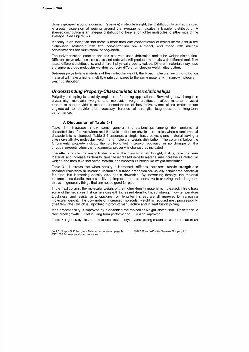
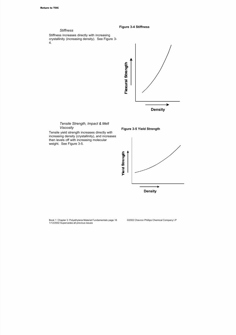
Stiffness
Stiffness increases directly with increasingcrystallinity (increasing density). See Figure 3-4.
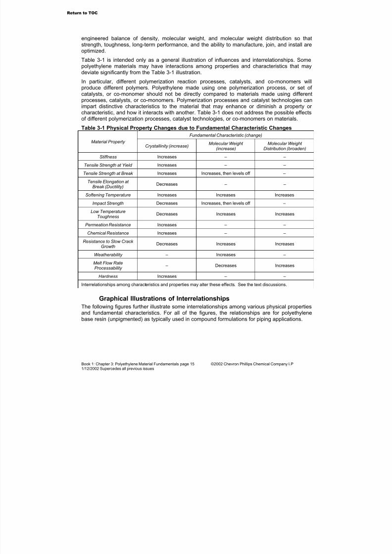
Tensile Strength, Impact & Melt Viscosity
Tensile yield strength increases directly with
increasing density (crystallinity), and increasesthen levels off with increasing molecular weight. See Figure 3-5.
Figure 3-4 Stiffness
Density
Density
Figure 3-5 Yield Strength
Return to TOC

7/23/2019 The Performance Pipe Engineering Manual
http://slidepdf.com/reader/full/the-performance-pipe-engineering-manual 18/208
Book 1: Chapter 3: Polyethylene Material Fundamentals page 17 ©2002 Chevron Phillips Chemical Company LP1/12/2002 Supercedes all previous issues
Tensile yield, break, and elongation areaffected by specimen preparation andmolecular orientation. Slow cooling maximizesdensity and yield strength, and minimizeselongation at break. Break strength is typicallyhigher than yield strength when molecules are
aligned with the strain (tensile pull) direction;break is lower than yield when alignment isacross the strain direction. When there is littleor no molecular orientation, break and yieldstrengths are about the same. See Figure 3-6.
Impact resistance decreases with increasingdensity, increases then levels off withincreasing molecular weight, and increaseswith broadening molecular weight, but to alesser extent.
Melt viscosity is the inverse of melt flow rate;that is, higher viscosity results in a lower meltflow rate. Melt viscosity increases (melt flowrate decreases) with increasing molecular
weight. Melt viscosity decreases (melt flow rateincreases) with broadening molecular weightdistribution. See Figure 3-7.
Figure 3-6 Tensile Strength vs. Molecular Orientation
Figure 3-7 Property Change vs. Molecular Weight
Strain (elongation)
1 2 3
1 - Aligned across pull
2 - Random alignment
3 - Aligned with pull
Increasing Molecular Weight
Pipe Polymer Range
Melt Viscosity
Impact
Tensile Strength
Return to TOC
7/23/2019 The Performance Pipe Engineering Manual
http://slidepdf.com/reader/full/the-performance-pipe-engineering-manual 19/208
Book 1: Chapter 3: Polyethylene Material Fundamentals page 18 ©2002 Chevron Phillips Chemical Company LP1/12/2002 Supercedes all previous issues
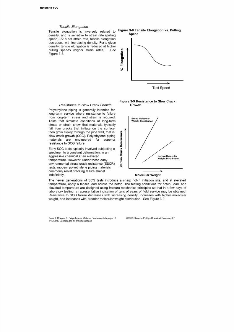
Tensile Elongation
Tensile elongation is inversely related todensity, and is sensitive to strain rate (pullingspeed). At a set strain rate, tensile elongationdecreases with increasing density. For a givendensity, tensile elongation is reduced at higher pulling speeds (higher strain rates). SeeFigure 3-8.
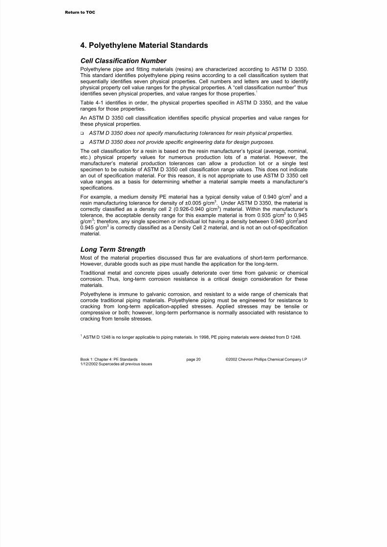
Resistance to Slow Crack Growth
Polyethylene piping is generally intended for long-term service where resistance to failurefrom long-term stress and strain is required.Tests that simulate conditions of long-termstress or strain show that materials typicallyfail from cracks that initiate on the surface,then grow slowly through the pipe wall, that is,
slow crack growth (SCG). Polyethylene pipingmaterials are engineered for superior resistance to SCG failure. Early SCG tests typically involved subjecting aspecimen to a constant deformation, in anaggressive chemical at an elevatedtemperature. However, under these earlyenvironmental stress crack resistance (ESCR)tests, modern polyethylene piping materialscommonly resist cracking failure almostindefinitely.
The newer generations of SCG tests introduce a sharp notch initiation site, and at elevatedtemperature, apply a tensile load across the notch. The testing conditions for notch, load, andelevated temperature are designed using fracture mechanics principles so that in a few days of laboratory testing, a representative indication of tens of years of field service may be obtained.Resistance to SCG failure decreases with increasing density, increases with higher molecular weight, and increases with broader molecular weight distribution. See Figure 3-9.
Figure 3-8 Tensile Elongation vs. PullingSpeed
Test Speed
Molecular Weight
Narrow Molecular Weight Distribution
Broad Molecular Weight Distribution
Figure 3-9 Resistance to Slow Crack
Growth
Return to TOC

7/23/2019 The Performance Pipe Engineering Manual
http://slidepdf.com/reader/full/the-performance-pipe-engineering-manual 20/208
Book 1: Chapter 3: Polyethylene Material Fundamentals page 19 ©2002 Chevron Phillips Chemical Company LP1/12/2002 Supercedes all previous issues
Permeation
The rate of permeation or activated diffusion of gasses is dependent upon polyethylenedensity (crystallinity) and the molecular weightof the permeating gas. Permeation bysolvating chemicals (such as liquidhydrocarbons) is generally greater at elevatedtemperatures, and when chemicalconcentrations are higher. In most circumstances, permeating (solvating)chemicals do not physically injure thepolyethylene material. Gasses diffuse veryslowly through the pipe wall, resulting in aslight loss of gas from within the pipe. Thevolume of gas that may permeate throughpolyethylene pipe is low. For example,methane permeation through a mile of DR 11 pipe at 60 psi is as low as 0.27 ft3 per day.
Caution — Solvating liquids will permeate the pipe wall, which may reduce long-termstrength, and may preclude the use of heat fusion joining.
Hardness
Hardness is tested against the Shore D scaleusing a spring-loaded penetrometer. Theprocedure is similar to hardness testing of metals, although plastics are generally much
softer than metals.
Density
Figure 3-10 Resistance to Permeation
Density
Figure 3-11 Hardness
Go to Chapter 4
Return to TOC
7/23/2019 The Performance Pipe Engineering Manual
http://slidepdf.com/reader/full/the-performance-pipe-engineering-manual 21/208
Book 1: Chapter 4: PE Standards page 20 ©2002 Chevron Phillips Chemical Company LP1/12/2002 Supercedes all previous issues
4. Polyethylene Material Standards
Cell Classification Number Polyethylene pipe and fitting materials (resins) are characterized according to ASTM D 3350.
This standard identifies polyethylene piping resins according to a cell classification system thatsequentially identifies seven physical properties. Cell numbers and letters are used to identifyphysical property cell value ranges for the physical properties. A “cell classification number” thusidentifies seven physical properties, and value ranges for those properties.1
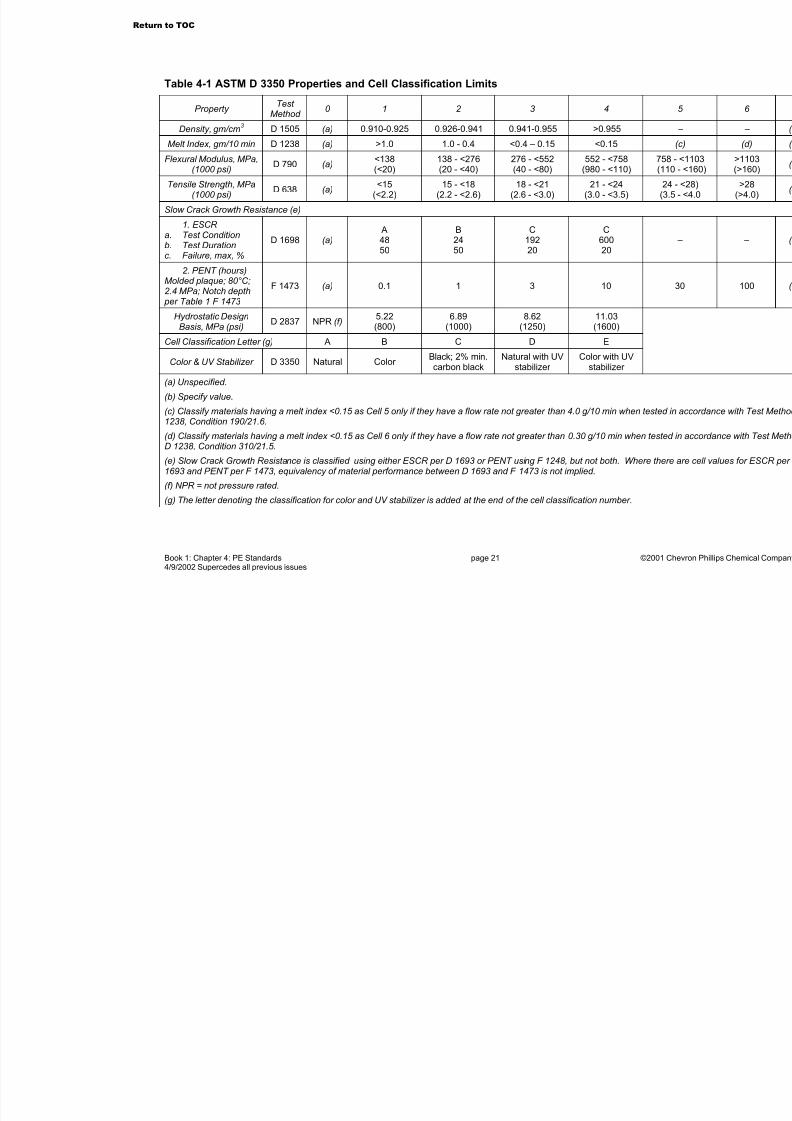
Table 4-1 identifies in order, the physical properties specified in ASTM D 3350, and the valueranges for those properties.
An ASTM D 3350 cell classification identifies specific physical properties and value ranges for these physical properties.
ASTM D 3350 does not specify manufacturing tolerances for resin physical properties.
ASTM D 3350 does not provide specific engineering data for design purposes.
The cell classification for a resin is based on the resin manufacturer’s typical (average, nominal,etc.) physical property values for numerous production lots of a material. However, themanufacturer’s material production tolerances can allow a production lot or a single testspecimen to be outside of ASTM D 3350 cell classification range values. This does not indicatean out of specification material. For this reason, it is not appropriate to use ASTM D 3350 cellvalue ranges as a basis for determining whether a material sample meets a manufacturer’sspecifications.
For example, a medium density PE material has a typical density value of 0.940 g/cm3 and aresin manufacturing tolerance for density of ±0.005 g/cm3. Under ASTM D 3350, the material iscorrectly classified as a density cell 2 (0.926-0.940 g/cm3) material. Within the manufacturer’stolerance, the acceptable density range for this example material is from 0.935 g/cm3 to 0.945
g/cm3
; therefore, any single specimen or individual lot having a density between 0.940 g/cm3
and0.945 g/cm3 is correctly classified as a Density Cell 2 material, and is not an out-of-specificationmaterial.
Long Term StrengthMost of the material properties discussed thus far are evaluations of short-term performance.However, durable goods such as pipe must handle the application for the long-term.
Traditional metal and concrete pipes usually deteriorate over time from galvanic or chemicalcorrosion. Thus, long-term corrosion resistance is a critical design consideration for thesematerials.
Polyethylene is immune to galvanic corrosion, and resistant to a wide range of chemicals thatcorrode traditional piping materials. Polyethylene piping must be engineered for resistance tocracking from long-term application-applied stresses. Applied stresses may be tensile or compressive or both; however, long-term performance is normally associated with resistance tocracking from tensile stresses.
1ASTM D 1248 is no longer applicable to piping materials. In 1998, PE piping materials were deleted from D 1248.
Return to TOC
7/23/2019 The Performance Pipe Engineering Manual
http://slidepdf.com/reader/full/the-performance-pipe-engineering-manual 22/208
Book 1: Chapter 4: PE Standards page 21 ©20014/9/2002 Supercedes all previous issues
Table 4-1 ASTM D 3350 Properties and Cell Classification Limits
Property Test
Method 0 1 2 3 4
Density, gm/cm3
D 1505 (a) 0.910-0.925 0.926-0.941 0.941-0.955 >0.955
Melt Index, gm/10 min D 1238 (a) >1.0 1.0 - 0.4 <0.4 – 0.15 <0.15
Flexural Modulus, MPa,(1000 psi)
D 790 (a)<138(<20)
138 - <276(20 - <40)
276 - <552(40 - <80)
552 - <758(980 - <110)
7(1
Tensile Strength, MPa(1000 psi)
D 638 (a)<15
(<2.2)15 - <18
(2.2 - <2.6)18 - <21
(2.6 - <3.0)21 - <24
(3.0 - <3.5) (
Slow Crack Growth Resistance (e)
1. ESCR a. Test Conditionb. Test Durationc. Failure, max, %
D 1698 (a) A4850
B2450
C19220
C60020
2. PENT (hours)Molded plaque; 80°C;2.4 MPa; Notch depth
per Table 1 F 1473
F 1473 (a) 0.1 1 3 10
Hydrostatic DesignBasis, MPa (psi)
D 2837 NPR (f) 5.22(800)
6.89(1000)
8.62(1250)
11.03(1600)
Cell Classification Letter (g) A B C D E
Color & UV Stabilizer D 3350 Natural Color Black; 2% min.carbon black
Natural with UVstabilizer
Color with UVstabilizer
(a) Unspecified.
(b) Specify value.
(c) Classify materials having a melt index <0.15 as Cell 5 only if they have a flow rate not greater than 4.0 g/10 min when teste1238, Condition 190/21.6.
(d) Classify materials having a melt index <0.15 as Cell 6 only if they have a flow rate not greater than 0.30 g/10 min when testD 1238, Condition 310/21.5.
(e) Slow Crack Growth Resistance is classified using either ESCR per D 1693 or PENT using F 1248, but not both. Where the1693 and PENT per F 1473, equivalency of material performance between D 1693 and F 1473 is not implied.
(f) NPR = not pressure rated.
(g) The letter denoting the classification for color and UV stabilizer is added at the end of the cell classification number.
Return to TOC

7/23/2019 The Performance Pipe Engineering Manual
http://slidepdf.com/reader/full/the-performance-pipe-engineering-manual 23/208
Book 1: Chapter 4: PE Standards page 22 ©2001 Chevron Phillips Chemical Company LP1/12/2002 Supercedes all previous issues
Externally applied tensile and compressive stresses may result from earthloads, or thermalexpansion or contraction. Internal (hoop) tensile stresses are applied when there is pressureinside the pipe. In general, higher stress, higher temperature, higher concentrations of aggressive chemicals, and cyclically applied stresses act to reduce lifetime.
Polyethylene pipe materials are evaluated for long-term stress by conducting long-term
sustained pressure tests per ASTM D 1598. Data from these tests are evaluated in accordancewith ASTM D 2837.
Based on the data, the temperature and the media inside the pipe, a long-term hydrostaticstress (LTHS) is determined. The LTHS is compared to hydrostatic design basis (HDB)categories to determine the HDB - the material’s long-term tensile stress rating at a temperatureand for a given fluid media. The HDB is used for pressure rating, and in engineering calculationsthat involve long-term tensile strength. Pressure rated polyethylene materials must also undergotesting and analysis to validate that a ductile to brittle transition will not occur during theprojected service period.
Lastly, the long-term performance of polyethylene piping in an application is highly dependentupon installation. When the piping and the installation are properly designed for the applicationand the pipe is properly installed in accordance with the installation design, application andinstallation related stresses are minimized, and long-term performance is maximized.
Application, design, and installation information is available in the Performance PipeEngineering Manual, Books 1, 2, and 3, information and standards from AGA, ASTM, AWWA,PPI, and others, and regulatory and codifying agencies.
Material Designation CodePolyethylene materials for pressure piping are commonly identified by an ASTM MaterialDesignation Code (PE 2406 or PE 3408). ASTM defines the Code as the letter abbreviation for the thermoplastic (PE for polyethylene), followed by two numbers that identify ASTM D 3350 cellvalues for density and slow crack growth resistance, followed by two numbers that identify the
material’s Hydrostatic Design Stress, HDS2
, in hundreds of psi with any tens and units dropped. ASTM Material Designation Codes for Performance Pipe pressure piping materials are:
Medium density - PE 2406
PE = polyethylene
2 = density cell 2
4 = SCG cell 4 or higher 3
06 = 630 psi HDS4
High density - PE 3408
PE = polyethylene
3 = density cell 3
4 = SCG cell 4 or higher 3
08 = 800 psi HDS
2The Hydrostatic Design Stress, HDS = HDB X f E , an environmental design factor.
3PE 2406 and PE 3408 materials used for ASTM D 2513 for gas distribution applications must have a SCG cell 6.
4Unless otherwise specified, the HDS is for water at 73°F (23°C), that is, HDS = HDB x 0.50.
Return to TOC
7/23/2019 The Performance Pipe Engineering Manual
http://slidepdf.com/reader/full/the-performance-pipe-engineering-manual 24/208
Book 1: Chapter 4: PE Standards page 23 ©2001 Chevron Phillips Chemical Company LP1/12/2002 Supercedes all previous issues
Performance Pipe MaterialsPerformance Pipe pressure-piping products are manufactured from either medium density or high-density polyethylene materials that have been engineered to provide the balance of properties required for the intended application. Medium density is usually produced in a yellowcolor, and used in gas distribution service. High-density materials are provided in black and
various colors. Different pigments are used for co-extruded striped or color shell pipe; however,the base resin is the same for pipe, shell and stripe.
Performance Pipe medium density polyethylene materials are listed by the Plastics PipeInstitute in PPI TR-4 with minimum standard grade hydrostatic design basis ratings of 1250psi (8.62 MPa) at 73° F (23° C) and 1000 psi (6.89 MPa) at 140° F (60° C) and meeting or exceeding an ASTM D 3350 cell classification of 234363E.
Performance Pipe high density polyethylene materials are listed by the Plastics PipeInstitute in PPI TR-4 with minimum standard grade hydrostatic design basis ratings of 1600psi (11.03 MPa) at 73° F (23° C) and 800 psi (5.52 MPa) at 140° F (60° C) and meeting or exceeding an ASTM D 3350 cell classification of 345464C for black.
DRISCOPLEX™ 2000 SPIROLITE high density polyethylene material meets or exceeds
ASTM D 3350 type and grade specification PE33, with a minimum ASTM D 3350 cellclassification of 335444C
Performance Pipe HDPE conduit is manufactured from utility-grade HDPE material that isengineered for the requirements of conduit applications including pull strength, stiffness,ESCR, density, melt index, chemical resistance and toughness.
Go to Chapter 5
Return to TOC
7/23/2019 The Performance Pipe Engineering Manual
http://slidepdf.com/reader/full/the-performance-pipe-engineering-manual 25/208
Book 1: Chapter 5: Environmental Effects page 24 ©2002 Chevron Phillips Chemical Company LP1/12/2002 Supercedes all previous issues
5. Environmental Effects
Resistance to Corrosion
Polyethylene is non-conductive and immune to galvanic and electrochemical effects. Thuspolyethylene will not corrode in the manner of metal and concrete piping. Both inside and out,Performance Pipe polyethylene pipe does not rust, rot, corrode or tuberculate.
Resistance to Stress Cracking Some polyethylene materials may fail from environmental stress cracking that results from thecombined actions of stress and the environment. Stress cracking is the slow growth andpropagation of cracks through the material by the action of sensitizing agents on minute surfaceflaws in stressed or strained materials.
Polymer structure, molecular weight, and molecular weight distribution will affect the stress
crack resistance of polyethylene. Performance Pipe polyethylenes show excellent resistance toenvironmental stress cracking. Please see the discussion below on “Resistance to Slow Crack Growth.”
Biological EffectsPerformance Pipe polyethylene pipe will not degrade due to biological effects. Polyethylenepiping materials are not digestible and do not contain ingredients that would attract burrowinginsects, animals, or worms. The exceptionally smooth surface of polyethylene pipe is notconducive to the growth of algae or other marine life on the pipe walls, especially under moderate and higher flow conditions.
Sunlight (Ultraviolet) EffectsWithout chemical or physical protection, polyethylene is degraded by ultraviolet (UV) light.Because ultraviolet light is present in sunlight, protective chemical systems are compoundedinto polyethylene pipe to prevent or delay the onset of UV degradation and allow use or storagein direct sunlight. UV protection systems are either blocking systems that are used in blackproducts, or sacrificial absorber systems that are used for color products.
Long term UV protection is provided by compounding 2% to 3% carbon black in the material.Very fine carbon black particles prevent UV degradation by blocking UV energy penetration.Black products are suitable for applications where there is long-term, direct exposure toultraviolet light. This includes all surface, suspended, and above grade applications.
Sacrificial UV absorbers temporarily protect colored products by absorbing UV energy, but are
used up in the process. Sacrificial absorber systems provide protection for uncovered outdoor storage of several months to several years depending upon protection level and exposure level.If left exposed, material degradation will eventually occur as the absorbers in the pipe are usedand the protection level drops. Covering the pipe will stop any further UV degradation effects,but will not reverse any prior exposure effects.
Return to TOC

7/23/2019 The Performance Pipe Engineering Manual
http://slidepdf.com/reader/full/the-performance-pipe-engineering-manual 26/208
Book 1: Chapter 5: Environmental Effects page 25 ©2002 Chevron Phillips Chemical Company LP1/12/2002 Supercedes all previous issues
The sacrificial UV absorber systems in colored products are designed only to allow areasonable period of unprotected outdoor storage prior to installation. Color products areintended for underground service — not for surface or above grade service where there will belong-term exposure to UV light in sunlight.
Recommendations for unprotected outdoor storage of colored products vary by product. Consult
your Performance Pipe Distributor, Performance Pipe Sales Representative, or PerformancePipe for information.
Thermal EffectsDRISCOPLEX™ PE 2406 and PE 3408 polyethylene pipe can be applied over a widetemperature range. These materials perform well from –50° F (-45° C) and below, to 140° F (60°C) for pressure service, or to up to 180° F (82° C) for gravity flow (non-pressure) service.Pressurized fluids must be in a flowable liquid or gaseous state.
Gravity flow service above 180° F (82° C) is not recommended. Pressure service above 140° F(60° C) is not recommended. For higher temperature applications, pressure ratings are lower.
Black polyethylene pipe that is on the surface or above grade is usually subject to sunlightheating that will raise the pipe service temperature. Temperature rise and fall will cause pipelength changes as it expands and contracts. See the Performance Pipe Engineering Manual Book 2: System Design for additional information.
Temperatures near or below freezing will affect polyethylene pipe by increasing stiffness andvulnerability to damage from suddenly applied stress or impact. Significant impact or shock loads against a polyethylene pipe that is at freezing or lower temperatures can fracture the pipe. Polyethylene pipe will be more difficult to uncoil or field bend in cold weather.
Chemical EffectsPerformance Pipe polyethylene pipes have outstanding resistance to a wide range of chemicals
and environmental conditions, making them ideal candidates for use with corrosive fluids andchemicals, and under harsh environmental conditions. If a chemical has an effect onpolyethylene, the effect may or may not be detrimental depending upon application or servicerequirements.
In some cases, a chemical may have little or no detrimental effect on polyethylene’s long termor mechanical properties, but its presence may affect a piping application.
For example, a surfactant may have little if any chemical effect, but it may coat the pipe bore,and change the pipe’s resistance to flow. Where water would normally bead up on the surfaceand flow with little resistance, it may “stick” to the surfactant, resulting in higher flow resistancein the pipe.
Some chemicals may affect polyethylene pipe joining. See “Solvents and Surface Cleaning” and
“Chemical Solvation (Permeation)”, below.
Resistance to Chemical Attack Where there is chemical effect or attack on polyethylene, environmental conditions andcombinations of conditions such as higher temperature, higher chemical concentration, higher applied stress, fatigue or combinations of chemicals may accelerate the effect. Chemicals thataffect the physical properties or long term performance of polyethylene typically act on the
Return to TOC

7/23/2019 The Performance Pipe Engineering Manual
http://slidepdf.com/reader/full/the-performance-pipe-engineering-manual 27/208
Book 1: Chapter 5: Environmental Effects page 26 ©2002 Chevron Phillips Chemical Company LP1/12/2002 Supercedes all previous issues
material by either chemical solvation, which causes the plastic to weaken, soften, or swell or bydirect chemical attack, which breaks down or alters the molecular structure. Chemical solvationeffects may be reversible, but direct chemical attack is usually is not.
Solvents and Surface Cleaning
There are no commercially available solvents that will dissolve solid polyethylene.
Polyethylene cannot be solvent cemented.
When joining polyethylene pipe, pipe surfaces must be clean and dry. Wiping with a clean drycloth is usually sufficient. Cleaning with a mild soap and water solution followed by a rinse withclean water is also acceptable. Chemical cleaning solvents are usually not required.
Cleaning solvents may have a chemical effect on the pipe, may leave a residue on the pipesurface, or may be chemically hazardous substances that require personal protective equipmentand special handling. The Material Safety Data Sheet (MSDS) for the chemical solvent shouldbe consulted for safety information.
Caution — Before using chemical solvents, the potential risks and hazards should be known,
and appropriate safety precautions taken.
Chemical Solvation (Permeation)Chemicals that solvate polyethylene typically do so by diffusing (permeating) into the material.Permeation does not usually degrade or dissolve the material, but it may weaken the material,cause swelling, or have other effects on the piping or the application. Higher temperaturesusually increase permeation effects. In some circumstances such as where a liquefiedhydrocarbon gas (liquid condensate) has permeated the material, removing the solvatingchemicals may allow the polyethylene to dry out and revert back to its original state.
Continuous exposure to some common chemicals and solvents such as liquid hydrocarbons(crude and fuel oils, gasoline, diesel fuel, kerosene, etc.) can allow these chemicals to diffuse or
permeate into the piping. Permeation can cause swelling, especially at elevated temperatures.
Permeation reduces strength — long-term pressure service ratings are significantly reduced.
Permeating chemicals such as liquid hydrocarbons typically cause little if any injury to thematerial; however hydrocarbons can contaminate and weaken heat fusion or electrofusion joints. When the pipe surface is melted, liquid hydrocarbons in the pipe will bubble out of thesurface causing porosity and contamination.
Caution — Where hydrocarbon contamination is indicated, heat fusion and electrofusion joining are not reliable. Use mechanical joining methods such as compression couplings with internal stiffeners, mechanical saddle fittings, etc., to join hydrocarbon permeated piping.
When the heating iron is removed from the pipe surface during heat fusion, contamination from
liquid hydrocarbon permeation is indicated by a rough, or sandpaper-like, or bubbly, or pock-marked surface appearance.
At low temperatures and higher pressures in fuel gas applications, heavier hydrocarbon gassessuch as propane or butane may condense and liquefy in the pipe. Such liquefied fuel gassesare known to permeate polyethylene pipe, and result in unreliable heat fusion or electrofusion joints.
In potable water applications, permeating chemicals could affect the pipe or water in the pipe. ANSI/AWWA standards provide the following guidance for potable water applications:
Return to TOC
7/23/2019 The Performance Pipe Engineering Manual
http://slidepdf.com/reader/full/the-performance-pipe-engineering-manual 28/208
Book 1: Chapter 5: Environmental Effects page 27 ©2002 Chevron Phillips Chemical Company LP1/12/2002 Supercedes all previous issues
“The selection of materials is critical for water service and distribution piping where there is likelihood the pipe will be exposed to significant concentrations of pollutants comprised of low molecular weight petroleum products or organic solvents or their vapors. Research has documented that pipe materials such as polyethylene, polybutylene, polyvinyl chloride, and asbestos cement, and elastomers, such as used in jointing gaskets and packing glands, may be subject
to permeation by lower molecular weight organic solvents or petroleum products.If water pipe must pass through such a contaminated area or an area subject tocontamination, consult with the manufacturer regarding permeation of pipe walls, jointing materials, and so forth, before selecting materials for use in that area.” 1
Chemical Attack A direct chemical attack on the polymer will result in permanent, irreversible polymer damage or chemical change by chain scission, cross-linking, oxidation, or substitution reactions. Removingthe chemical cannot reverse direct chemical attack damage or change.
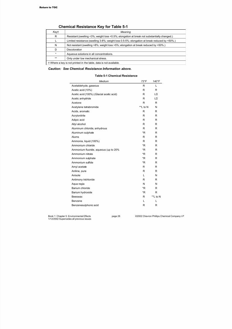
Chemical Resistance InformationThe data in Table 5-1 is representative of short-term chemical immersion tests of unstressedspecimens. Typical chemical immersion testing involves submerging a material test specimenin the chemical for several days; then testing some physical properties of the specimen after removal. Unless stated otherwise, tests were conducted in the relatively pure or concentratedchemical.
DISCLAIMER
Because the particular conditions of an application may vary, Table 5-1 informationshould be used only as a preliminary guide for Performance Pipe polyethylene pipematerials. This information is offered in good faith, and is believed to be accurate at thetime of publication, but it is offered without any warranty, express or implied, and
specifically excluding implied warranties of merchantability and fitness for a particular purpose. Additional information may be required, particularly with regard to unusual or special applications. Determinations of suitability for use in particular chemical or environmental conditions may require specialized laboratory testing.
In general, dilute chemical solutions, lower temperatures, and the absence of stress reduce thepotential to affect the material. Higher concentrations, higher temperature, applied stress andcombinations of chemicals may reduce resistance or may affect the material where more benignconditions may not. The apparent absence of effect in a short-term immersion test doesnot imply that there will be no effect where there is long-term exposure or applied stressor combinations chemicals or elevated temperature either individually or in any combination.
Where information about the suitability of polyethylene piping for use with chemicals or chemicalcombinations for a particular application or environment is not available, tests should beconducted to determine suitability. Performance Pipe cannot provide chemical testing services.
Additional information on chemical compatibility may be found in PPI TR-19, Thermoplastic Piping for the Transport of Chemicals.
1Quoted text from ANSI/AWWA C901 and ANSI/AWWA C906.
Return to TOC
7/23/2019 The Performance Pipe Engineering Manual
http://slidepdf.com/reader/full/the-performance-pipe-engineering-manual 29/208
Book 1: Chapter 5: Environmental Effects page 28 ©2002 Chevron Phillips Chemical Company LP1/12/2002 Supercedes all previous issues
Chemical Resistance Key for Table 5-1
Key † Meaning
R Resistant (swelling <3%; weight loss <0.5%; elongation at break not substantially changed.)
L Limited resistance (swelling 3-8%; weight loss 0.5-5%; elongation at break reduced by <50%.)
N Not resistant (swelling >8%; weight loss >5%; elongation at break reduced by >50%.)
D Discoloration
* Aqueous solutions in all concentrations.
** Only under low mechanical stress.
† Where a key is not printed in the table, data is not available.
Caution: See Chemical Resistance Information above.
Table 5-1 Chemical Resistance
Medium 73°F 140°F
Acetaldehyde, gaseous R L
Acetic acid (10%) R R
Acetic acid (100%) (Glacial acetic acid) R LD
Acetic anhydride R LD
Acetone R R
Acetylene tetrabromide **L to N N
Acids, aromatic R R
Acrylonitrile R R
Adipic acid R R
Allyl alcohol R R
Aluminum chloride, anhydrous R R
Aluminum sulphate *R R Alums R R
Ammonia, liquid (100%) R R
Ammonium chloride *R R
Ammonium fluoride, aqueous (up to 20% *R R
Ammonium nitrate *R R
Ammonium sulphate *R R
Ammonium sulfide *R R
Amyl acetate R R
Aniline, pure R R
Anisole L N
Antimony trichloride R R
Aqua regia N N
Barium chloride *R R
Barium hydroxide *R R
Beeswax R **L to N
Benzene L L
Benzenesulphonic acid R R
Return to TOC
7/23/2019 The Performance Pipe Engineering Manual
http://slidepdf.com/reader/full/the-performance-pipe-engineering-manual 30/208
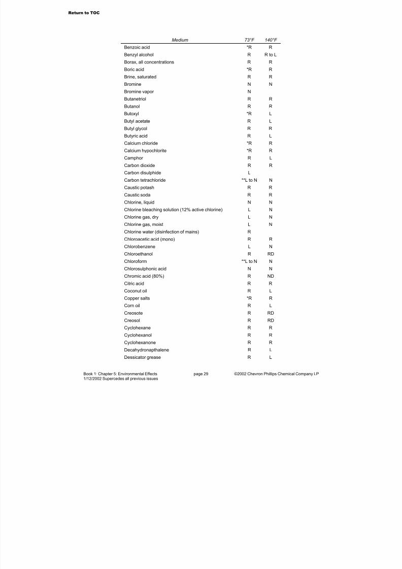
Book 1: Chapter 5: Environmental Effects page 29 ©2002 Chevron Phillips Chemical Company LP1/12/2002 Supercedes all previous issues
Medium 73°F 140°F
Benzoic acid *R R
Benzyl alcohol R R to L
Borax, all concentrations R R
Boric acid *R R
Brine, saturated R R
Bromine N N
Bromine vapor N
Butanetriol R R
Butanol R R
Butoxyl *R L
Butyl acetate R L
Butyl glycol R R
Butyric acid R L
Calcium chloride *R R
Calcium hypochlorite *R R
Camphor R L
Carbon dioxide R R
Carbon disulphide L
Carbon tetrachloride **L to N N
Caustic potash R R
Caustic soda R R
Chlorine, liquid N N
Chlorine bleaching solution (12% active chlorine) L N
Chlorine gas, dry L N
Chlorine gas, moist L N
Chlorine water (disinfection of mains) R
Chloroacetic acid (mono) R R
Chlorobenzene L N
Chloroethanol R RD
Chloroform **L to N N
Chlorosulphonic acid N N
Chromic acid (80%) R ND
Citric acid R R
Coconut oil R L
Copper salts *R R
Corn oil R LCreosote R RD
Creosol R RD
Cyclohexane R R
Cyclohexanol R R
Cyclohexanone R R
Decahydronapthalene R L
Dessicator grease R L
Return to TOC
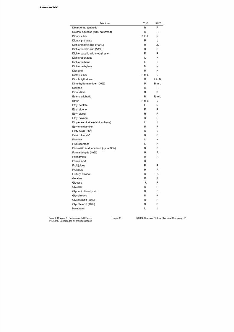
7/23/2019 The Performance Pipe Engineering Manual
http://slidepdf.com/reader/full/the-performance-pipe-engineering-manual 31/208
Book 1: Chapter 5: Environmental Effects page 30 ©2002 Chevron Phillips Chemical Company LP1/12/2002 Supercedes all previous issues
Medium 73°F 140°F
Detergents, synthetic R R
Dextrin, aqueous (18% saturated) R R
Dibutyl ether R to L N
Dibutyl phthalate R L
Dichloroacetic acid (100%) R LD
Dichloroacetic acid (50%) R R
Dichloroacetic acid methyl ester R R
Dichlorobenzene L N
Dichloroethane L L
Dichloroethylene N N
Diesel oil R N
Diethyl ether R to L L
Diisobutyl ketone R L to N
Dimethyl formamide (100%) R R to L
Dioxane R R
Emulsifiers R R
Esters, aliphatic R R to L
Ether R to L L
Ethyl acetate L N
Ethyl alcohol R R
Ethyl glycol R R
Ethyl hexanol R R
Ethylene chloride (dichlorothene) L L
Ethylene diamine R R
Fatty acids (>C6) R L
Ferric chloride* R R
Fluorine N N
Fluorocarbons L N
Fluorosilic acid, aqueous (up to 32%) R R
Formaldehyde (40%) R R
Formamide R R
Formic acid R
Fruit juices R R
Fruit pulp R R
Furfuryl alcohol R RD
Gelatine R RGlucose *R R
Glycerol R R
Glycerol chlorohydrin R R
Glycol (conc.) R R
Glycolic acid (50%) R R
Glycolic acid (70%) R R
Halothane L L
Return to TOC

7/23/2019 The Performance Pipe Engineering Manual
http://slidepdf.com/reader/full/the-performance-pipe-engineering-manual 32/208
Book 1: Chapter 5: Environmental Effects page 31 ©2002 Chevron Phillips Chemical Company LP1/12/2002 Supercedes all previous issues
Medium 73°F 140°F
Hydrazine hydrate R R
Hydrobromic acid R R
Hydrochloric acid (all concentrations) R R
Hydrocyanic acid R R
Hydrofluoric acid (40%) R L
Hydrofluoric acid (70%) R L
Hydrogen R R
Hydrogen chloride gas, moist and dry R R
Hydrogen peroxide (30%) R R
Hydrogen peroxide (100%) R
Hydrogen sulfide R R
Iodine, tincture of, DAB 7 (German Pharmacopeia) R LD
Isooctane R L
Isopropanol R R
Isopropyl ether R to L N
Jam R R
Ketones R R to L
Lactic acid R R
Lead acetate *R R
Linseed oil R R
Magnesium chloride *R R
Magnesium sulphate *R R
Maleic acid R R
Malic acid R R
Menthol R L
Mercuric chloride (sublimate) R R
Mercury R R
Methanol R R
Methyl butanol R R
Methyl ethyl ketone R L to N
Methyl glycol R R
Methylene chloride L L
Mineral oils R R to L
Molasses R R
Monochloroacetic acid R R
Monochloroacetic ethyl ester R RMonochloroacetic methyl ester R R
Morpholine R R
Naptha R L
Napthalene R L
Nickel salts *R R
Nitric acid (25%) R R
Nitric acid (50%) L N
Return to TOC

7/23/2019 The Performance Pipe Engineering Manual
http://slidepdf.com/reader/full/the-performance-pipe-engineering-manual 33/208
Book 1: Chapter 5: Environmental Effects page 32 ©2002 Chevron Phillips Chemical Company LP1/12/2002 Supercedes all previous issues
Medium 73°F 140°F
Nitrobenzene R L
o-Nitrotolulene R L
Octyl creosol L N
Oils, ethereal L L
Oils, vegetable and animal R R to L
Oleic acid (conc.) R L
Oxalic acid (50%) R R
Ozone L N
Ozone, aqueous solution (Drinking water purification) R
Paraffin oil R R
Perchloric acid (20%) R R
Perchloric acid (50%) R L
Perchloric acid (70%) R ND
Petrol R R to L
Petroleum R L
Petroleum ether R L
Petroleum jelly **R to L L
Phenol R RD
Phosphates *R R
Phosphoric acid (25%) R R
Phosphoric acid (50%) R R
Phosphoric acid (95%) R LD
Phosphorus oxychloride R LD
Phosphorus pentoxide R R
Phosphorus trichloride R L
Photographic developers, commercial R R
Phthalic acid (50%) R R
Polyglycols R R
Potassium bichromate (40%) R R
Potassium borate, aqueous (1%) R R
Potassium bromate, aqueous (up to 10%) R R
Potassium bromide *R R
Potassium chloride *R R
Potassium chromate, aqueous (40%) R
Potassium cyanide *R R
Potassium hydroxide (30% solution) R RPotassium nitrate *R R
Potassium permanganate R RD
Propanol R R
Propionic acid (50%) R R
Propionic acid (100%) R L
Propylene glycol R R
Pseudocumene L L
Return to TOC
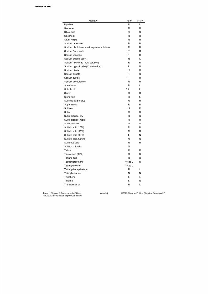
7/23/2019 The Performance Pipe Engineering Manual
http://slidepdf.com/reader/full/the-performance-pipe-engineering-manual 34/208
Book 1: Chapter 5: Environmental Effects page 33 ©2002 Chevron Phillips Chemical Company LP1/12/2002 Supercedes all previous issues
Medium 73°F 140°F
Pyridine R L
Seawater R R
Silicic acid R R
Silicone oil R R
Silver nitrate R R
Sodium benzoate R R
Sodium bisulphate, weak aqueous solutions R R
Sodium Carbonate *R R
Sodium Chloride *R R
Sodium chlorite (50%) R L
Sodium hydroxide (30% solution) R R
Sodium hypochlorite (12% solution) L N
Sodium nitrate *R R
Sodium silicate *R R
Sodium sulfide *R R
Sodium thiosulphate R R
Spermaceti R L
Spindle oil R to L L
Starch R R
Steric acid R L
Succinic acid (50%) R R
Sugar syrup R R
Sulfates *R R
Sulfur R R
Sulfur dioxide, dry R R
Sulfur dioxide, moist R R
Sulfur trioxide N N
Sulfuric acid (10%) R R
Sulfuric acid (50%) R R
Sulfuric acid (98%) L N
Sulfuric acid, fuming N N
Sulfurous acid R R
Sulfuryl chloride N
Tallow R R
Tannic acid (10%) R R
Tartaric acid R RTetrachloroethane **R to L N
Tetrahydrofuran **R to L
Tetrahydronapthalene R L
Thionyl chloride N N
Thiophene L L
Toluene L N
Transformer oil R L
Return to TOC
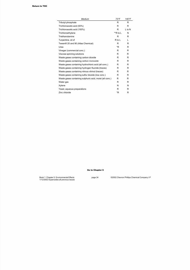
7/23/2019 The Performance Pipe Engineering Manual
http://slidepdf.com/reader/full/the-performance-pipe-engineering-manual 35/208
Book 1: Chapter 5: Environmental Effects page 34 ©2002 Chevron Phillips Chemical Company LP1/12/2002 Supercedes all previous issues
Medium 73°F 140°F
Tributyl phosphate R R
Trichloroacetic acid (50%) R R
Trichloroacetic acid (100%) R L to N
Trichloroethylene **R to L N
Triethanolamine R R
Turpentine, oil of R to L L
Tween® 20 and 90 (Atlas Chemical) R R
Urea *R R
Vinegar (commercial conc.) R R
Viscose spinning solutions R R
Waste gases containing carbon dioxide R R
Waste gases containing carbon monoxide R R
Waste gases containing hydrochloric acid (all conc.) R R
Waste gases containing hydrogen fluoride (traces) R R
Waste gases containing nitrous vitrinol (traces) R R
Waste gases containing sulfur dioxide (low conc.) R R
Waste gases containing sulphuric acid, moist (all conc.) R R
Water gas R R
Xylene N N
Yeast, aqueous preparations R R
Zinc chloride *R R
Go to Chapter 6
Return to TOC

7/23/2019 The Performance Pipe Engineering Manual
http://slidepdf.com/reader/full/the-performance-pipe-engineering-manual 36/208
Book 1: Chapter 6: Organizations, Standards &Publications page 35 ©2002 Chevron Phillips Chemical Company LP1/12/2002 Supercedes all previous issues
6. Organizations, Standards & Publications
Organizations AASHTO – American Association of State Highway & Transportation Officials, 444 North Capitol
Street N.W., Suite 249, Washington, DC 20001; www.aashto.org.
AGA - American Gas Association, 1515 Wilson Boulevard, Arlington, VA 22209; www.AGA.org.
ANSI - American National Standards Institute, 11 West 42nd Street, New York, NY 10036;www.ANSI.org.
ASCE – American Society of Civil Engineers, 1801 Alexander Bell Drive, Reston, Virginia20191-4400; www.asce.org.
ASME – American Society of Mechanical Engineers International, 22 Law Drive, Fairfield, NJ07007-2900; www.asme.org
ASQC - American Society for Quality Control, 611 East Wisconsin Avenue, Milwaukee, WI53202
ASTM - American Society for Testing and Materials, 100 Barr Harbor Drive, WestConshohocken, PA 19428-2959; www.ASTM.org
AWWA - American Water Works Association, 666 West Quincy Avenue, Denver, CO 80235;www.AWWA.org.
IAPMO – International Association of Plumbing and Mechanical Officials, 20001 East WalnutDrive South, Walnut, CA 91789-2825; www.iapmo.com
ISO - International Organization for Standardization, Geneva, Switzerland; http://www.iso.ch/
NSF – NSF International, 789 Dixboro Road, P.O. Box 130140, Ann Arbor, MI 48113-0140;www.nsf.org.
PPI - Plastics Pipe Institute, 1801 K Street NW, Suite 600K, Washington, DC 2006-1301;www.plasticpipe.org
Standards AASHTO Standard Wheel Loadings For Standard H And HS Trucks - Standard SpecificationsFor Highway Bridges
AASHTO T-99 (ASTM D 698) - Test Method for Laboratory Compaction Characteristics of Soil Using Standard Effort
ANSI/ASQC Q9002 Quality Systems—Model for Quality Assurance in Production, Installationand Servicing
ANSI/AWWA C651 Disinfecting Water Mains
ANSI/AWWA C901 Polyethylene (PE) Pressure Pipe and Tubing, 1/2 in. (13 mm) through 3 in.(76 mm) for Water Service
ANSI/AWWA C906 Polyethylene (PE) Pressure Pipe and Fittings, 4 in., through 63 in., for Water Distribution
ASCE Manuals And Reports On Engineering Practice - No. 60 Gravity Sanitary Sewer Designand Construction
Return to TOC
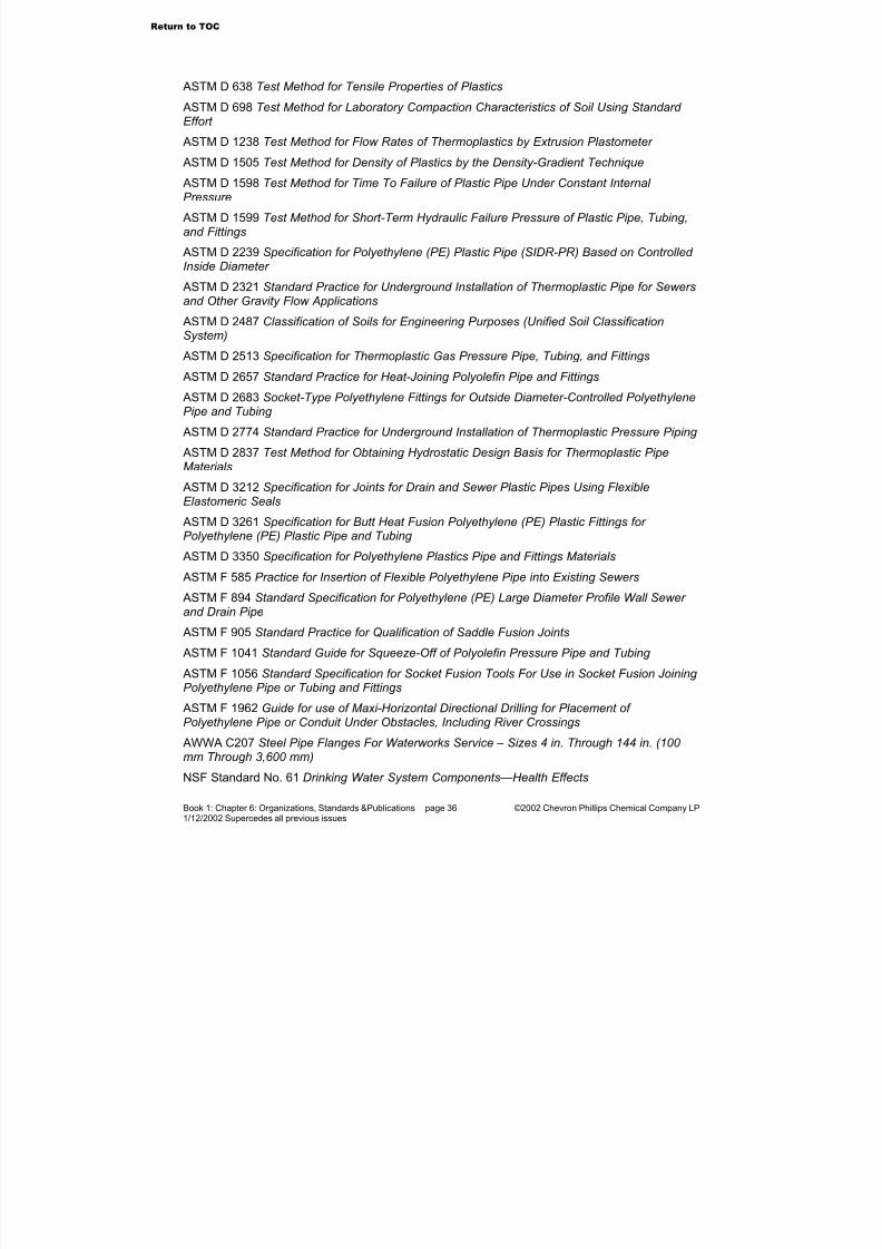
7/23/2019 The Performance Pipe Engineering Manual
http://slidepdf.com/reader/full/the-performance-pipe-engineering-manual 37/208
Book 1: Chapter 6: Organizations, Standards &Publications page 36 ©2002 Chevron Phillips Chemical Company LP1/12/2002 Supercedes all previous issues
ASTM D 638 Test Method for Tensile Properties of Plastics
ASTM D 698 Test Method for Laboratory Compaction Characteristics of Soil Using Standard Effort
ASTM D 1238 Test Method for Flow Rates of Thermoplastics by Extrusion Plastometer
ASTM D 1505 Test Method for Density of Plastics by the Density-Gradient Technique ASTM D 1598 Test Method for Time To Failure of Plastic Pipe Under Constant Internal Pressure
ASTM D 1599 Test Method for Short-Term Hydraulic Failure Pressure of Plastic Pipe, Tubing,and Fittings
ASTM D 2239 Specification for Polyethylene (PE) Plastic Pipe (SIDR-PR) Based on Controlled Inside Diameter
ASTM D 2321 Standard Practice for Underground Installation of Thermoplastic Pipe for Sewersand Other Gravity Flow Applications
ASTM D 2487 Classification of Soils for Engineering Purposes (Unified Soil Classification
System) ASTM D 2513 Specification for Thermoplastic Gas Pressure Pipe, Tubing, and Fittings
ASTM D 2657 Standard Practice for Heat-Joining Polyolefin Pipe and Fittings
ASTM D 2683 Socket-Type Polyethylene Fittings for Outside Diameter-Controlled PolyethylenePipe and Tubing
ASTM D 2774 Standard Practice for Underground Installation of Thermoplastic Pressure Piping
ASTM D 2837 Test Method for Obtaining Hydrostatic Design Basis for Thermoplastic PipeMaterials
ASTM D 3212 Specification for Joints for Drain and Sewer Plastic Pipes Using Flexible
Elastomeric Seals ASTM D 3261 Specification for Butt Heat Fusion Polyethylene (PE) Plastic Fittings for Polyethylene (PE) Plastic Pipe and Tubing
ASTM D 3350 Specification for Polyethylene Plastics Pipe and Fittings Materials
ASTM F 585 Practice for Insertion of Flexible Polyethylene Pipe into Existing Sewers
ASTM F 894 Standard Specification for Polyethylene (PE) Large Diameter Profile Wall Sewer and Drain Pipe
ASTM F 905 Standard Practice for Qualification of Saddle Fusion Joints
ASTM F 1041 Standard Guide for Squeeze-Off of Polyolefin Pressure Pipe and Tubing
ASTM F 1056 Standard Specification for Socket Fusion Tools For Use in Socket Fusion Joining Polyethylene Pipe or Tubing and Fittings
ASTM F 1962 Guide for use of Maxi-Horizontal Directional Drilling for Placement of Polyethylene Pipe or Conduit Under Obstacles, Including River Crossings
AWWA C207 Steel Pipe Flanges For Waterworks Service – Sizes 4 in. Through 144 in. (100 mm Through 3,600 mm)
NSF Standard No. 61 Drinking Water System Components—Health Effects
Return to TOC
7/23/2019 The Performance Pipe Engineering Manual
http://slidepdf.com/reader/full/the-performance-pipe-engineering-manual 38/208
Book 1: Chapter 6: Organizations, Standards &Publications page 37 ©2002 Chevron Phillips Chemical Company LP1/12/2002 Supercedes all previous issues
USBR (United States Bureau of Reclamation) Designation E-3 (ASTM D 2487) Classification of Soils for Engineering Purposes (Unified Soil Classification System)
USBR (United States Bureau of Reclamation) Designation E-11 (ASTM D 698) Test Method for Laboratory Compaction Characteristics of Soil Using Standard Effort
Other PublicationsPPI TR-4 Recommended Hydrostatic Strengths and Design Stresses for Thermoplastic Pipeand Fittings Compounds
PPI TR-19 Thermoplastics Piping for the Transport of Chemicals
Go to Book 2: Chapter 1
Return to TOC

7/23/2019 The Performance Pipe Engineering Manual
http://slidepdf.com/reader/full/the-performance-pipe-engineering-manual 39/208
CPChem
a dia dia dia dia division of vision of vision of vision of vision of CheCheCheCheChevr vr vr vr vr on Phillips Chemical Companon Phillips Chemical Companon Phillips Chemical Companon Phillips Chemical Companon Phillips Chemical Company LPy LPy LPy LPy LP
PERFORMANCE PIPEPERFORMANCE PIPEPERFORMANCE PIPEPERFORMANCE PIPEPERFORMANCE PIPE
TM
©2002 Performance PipeTM
The Performance PipeTM
Engineering Manual
Book 2: System Design
All rights reserved. This publicaiton is fully protected by copyright and nothing that appears in it may
be reprinted, copied, or otherwise reproduced by any means including electronic media, either wholly
or in part, without the express written permission of Performance PipeTM a division of Chevron Phillips
Chemical Company LP.
NOTICE -- This Manual is intended to be used as a guide to support the designer of polyethylene
piping systems. It is not intended to be used as installation instructions, and should not be substi-
tuted in place of the advice of a professional design engineer. There may be a more current version
of this manual. Contact Performance PipeTM for more informantion.
PLEXCO, PLEXVUE, and YELLOWSTRIPE are registered trademarks of Chevron Phillips
Chemical Company LP in the United States of America; BLUESTRIPE, CP CHEM, DRISCOPLEX,
GREENSTRIPE, PERFORMANCE PIPE, PLEXCO BLUESTRIPE, PLEXSHIELD, PLEXSTRIPE,
PURPLESTRIPE, REDSTRIPE, and SPIROLITE are trademarks of Chevron Phillips Chemical
Company LP in the United States of America.
Return to TOC

7/23/2019 The Performance Pipe Engineering Manual
http://slidepdf.com/reader/full/the-performance-pipe-engineering-manual 40/208
Book 2: Chapter 1: Introduction page 38 ©2002 Chevron Phillips Chemical Company LP1/12/2002 Supercedes all previous issues
1. Introduction
Performance Pipe DRISCOPLEX™ polyethylene piping systems are used to transport gasses,liquids and slurries. These systems may operate under internal or external pressure, or both,and may be designed for buried, surface, above grade, underwater, or floating applications.
Each system requires attention to the piping design characteristics of materials and products inaccordance with application and installation requirements.
There are many different piping, materials available to the piping system designer - wood,concrete, steel, ductile iron, polyethylene, fiberglass, etc. Each material has its own advantagesand disadvantages when considered for a particular application or installation.
Piping systems are best designed when the appropriate material and product characteristics areaccommodated. Applying design methods for other piping materials to polyethylene pipingsystems may lead to unsatisfactory system performance. Polyethylene will behave just likepolyethylene – not like steel, not like concrete, not like other commercial piping materials.
A piping system is an assembly of piping components - pipe, fittings, valves, pumps, and other appurtenances – all joined together to perform a particular function. So, component joining
methods are crucial to the performance of the system as a whole.
• DRISCOPLEX™ polyethylene pipes are produced under two distinctly differentmanufacturing processes. These processes define the product and the applicable joiningmethods.
• DRISCOPLEX™ polyethylene piping products are designed for high performance, and easy,efficient joining both to themselves and to other piping system components.
• DRISCOPLEX™ polyethylene piping products have many characteristics that are commonto polyethylene, and in some cases, specific to Performance Pipe products.
The second book of the Performance Pipe Engineering Manual, System Design, is intended asa guide for the piping system designer in the application of Performance Pipe DRISCOPLEX™
polyethylene piping products.
Performance Pipe Distributors, Sales, Customer Service and Technical personnel are availablefor guidance with specific design concerns.
DRISCOPLEX™ Outside Diameter (OD) Controlled Polyethylene PipeDRISCOPLEX™ OD Controlled polyethylene pipe is extruded using a process andspecifications that control the pipe outside diameter and wall thickness.
The controlled outside diameter manufacturing process lends itself well to joining by heat fusion,which melts the joining surfaces and joins them, then cools them under pressure. Whenproperly made, heat fusion joints are as strong and permanent as the pipe.
DRISCOPLEX™ polyethylene pipe and fittings for OD controlled PE pipe are primarily designedfor internal pressure service, but provide excellent performance in non-pressure applications aswell. Pipe joints for pressure service are fully restrained, so the system retains polyethylene'soutstanding elasticity, ductility, and flexibility. When joined, systems can withstand unstablesoils, frost heave, tidal flows and wave action, pressure surges, and wide temperature swings.
DRISCOPLEX™ OD Controlled PE pipe is available in standard CTS tubing outside diametersfrom 1/2 in. through 2 in.; standard IPS outside diameters from 1/2 in. through 54 in.; standardDuctile Iron Pipe Sizes (DIPS) from 3 in. through 48 in., and standard metric sizes from 16 mm
Return to TOC
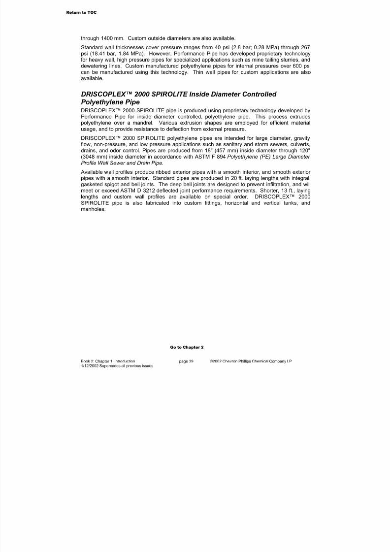
7/23/2019 The Performance Pipe Engineering Manual
http://slidepdf.com/reader/full/the-performance-pipe-engineering-manual 41/208
Book 2: Chapter 1: Introduction page 39 ©2002 Chevron Phillips Chemical Company LP1/12/2002 Supercedes all previous issues
through 1400 mm. Custom outside diameters are also available.
Standard wall thicknesses cover pressure ranges from 40 psi (2.8 bar; 0.28 MPa) through 267psi (18.41 bar, 1.84 MPa). However, Performance Pipe has developed proprietary technologyfor heavy wall, high pressure pipes for specialized applications such as mine tailing slurries, anddewatering lines. Custom manufactured polyethylene pipes for internal pressures over 600 psi
can be manufactured using this technology. Thin wall pipes for custom applications are alsoavailable.
DRISCOPLEX™ 2000 SPIROLITE Inside Diameter Controlled Polyethylene PipeDRISCOPLEX™ 2000 SPIROLITE pipe is produced using proprietary technology developed byPerformance Pipe for inside diameter controlled, polyethylene pipe. This process extrudespolyethylene over a mandrel. Various extrusion shapes are employed for efficient materialusage, and to provide resistance to deflection from external pressure.
DRISCOPLEX™ 2000 SPIROLITE polyethylene pipes are intended for large diameter, gravityflow, non-pressure, and low pressure applications such as sanitary and storm sewers, culverts,
drains, and odor control. Pipes are produced from 18" (457 mm) inside diameter through 120"(3048 mm) inside diameter in accordance with ASTM F 894 Polyethylene (PE) Large Diameter Profile Wall Sewer and Drain Pipe.
Available wall profiles produce ribbed exterior pipes with a smooth interior, and smooth exterior pipes with a smooth interior. Standard pipes are produced in 20 ft. laying lengths with integral,gasketed spigot and bell joints. The deep bell joints are designed to prevent infiltration, and willmeet or exceed ASTM D 3212 deflected joint performance requirements. Shorter, 13 ft., layinglengths and custom wall profiles are available on special order. DRISCOPLEX™ 2000SPIROLITE pipe is also fabricated into custom fittings, horizontal and vertical tanks, andmanholes.
Go to Chapter 2
Return to TOC
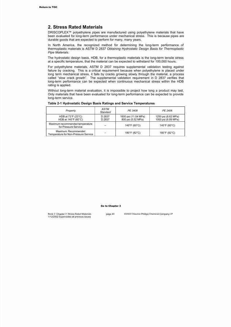
7/23/2019 The Performance Pipe Engineering Manual
http://slidepdf.com/reader/full/the-performance-pipe-engineering-manual 42/208
Book 2: Chapter 2: Stress Rated Materials page 40 ©2002 Chevron Phillips Chemical Company LP1/12/2002 Supercedes all previous issues
2. Stress Rated MaterialsDRISCOPLEX™ polyethylene pipes are manufactured using polyethylene materials that havebeen evaluated for long-term performance under mechanical stress. This is because pipes aredurable goods that are expected to perform for many, many years.
In North America, the recognized method for determining the long-term performance of thermoplastic materials is ASTM D 2837 Obtaining Hydrostatic Design Basis for Thermoplastic Pipe Materials.
The hydrostatic design basis, HDB, for a thermoplastic materials is the long-term tensile stressat a specific temperature, that the material can be expected to withstand for 100,000 hours.
For polyethylene materials, ASTM D 2837 requires supplemental validation testing againstfailure by cracking. This is a critical requirement because when polyethylene is placed under long term mechanical stress, it fails by cracks growing slowly through the material, a processcalled “slow crack growth”. The supplemental validation requirement in D 2837 verifies thatlong-term performance can be expected when continuous mechanical stress within the HDBrating is applied.
Without long-term material evaluation, it is impossible to project how long a product may last.Only materials that have been evaluated for long-term performance can be expected to providelong-term service.
Table 2-1 Hydrostatic Design Basis Ratings and Service Temperatures
Property ASTM
Standard PE 3408 PE 2406
HDB at 73°F (23°C)HDB at 140°F (60°C)
D 2837D 2837
1600 psi (11.04 MPa)800 psi (5.52 MPa)
1250 psi (8.62 MPa)1000 psi (6.89 MPa)
Maximum recommended temperaturefor Pressure Service
– 140°F (60°C) 140°F (60°C)
Maximum RecommendedTemperature for Non-Pressure Service – 180°F (82°C) 180°F (82°C)
Go to Chapter 3
Return to TOC
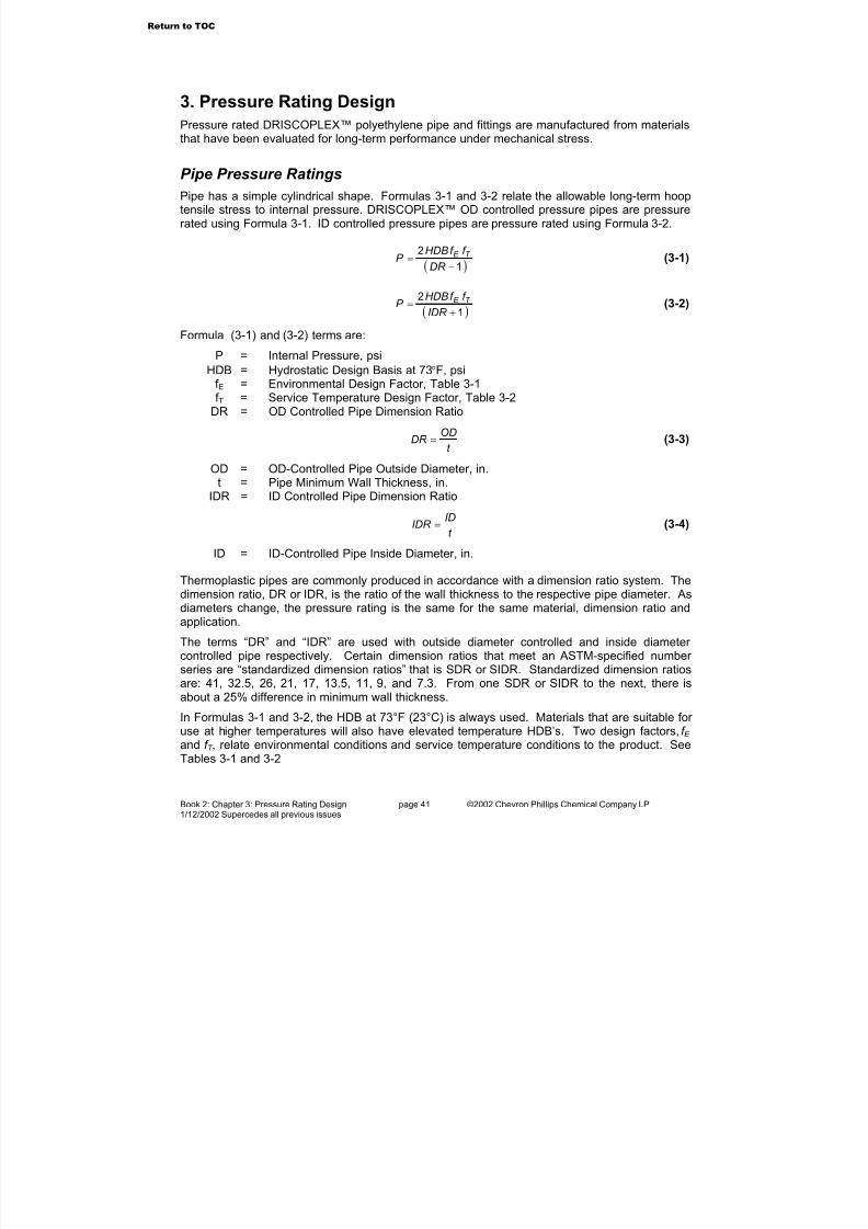
7/23/2019 The Performance Pipe Engineering Manual
http://slidepdf.com/reader/full/the-performance-pipe-engineering-manual 43/208
Book 2: Chapter 3: Pressure Rating Design page 41 ©2002 Chevron Phillips Chemical Company LP1/12/2002 Supercedes all previous issues
3. Pressure Rating Design
Pressure rated DRISCOPLEX™ polyethylene pipe and fittings are manufactured from materialsthat have been evaluated for long-term performance under mechanical stress.
Pipe Pressure Ratings
Pipe has a simple cylindrical shape. Formulas 3-1 and 3-2 relate the allowable long-term hooptensile stress to internal pressure. DRISCOPLEX™ OD controlled pressure pipes are pressurerated using Formula 3-1. ID controlled pressure pipes are pressure rated using Formula 3-2.
( )1
2
−=
DR
f f HDBP T E (3-1)
( )1
2
+=
IDR
f f HDBP T E (3-2)
Formula (3-1) and (3-2) terms are:
P = Internal Pressure, psi
HDB = Hydrostatic Design Basis at 73°F, psif E = Environmental Design Factor, Table 3-1f T = Service Temperature Design Factor, Table 3-2
DR = OD Controlled Pipe Dimension Ratio
t
ODDR = (3-3)
OD = OD-Controlled Pipe Outside Diameter, in.t = Pipe Minimum Wall Thickness, in.
IDR = ID Controlled Pipe Dimension Ratio
t
IDIDR = (3-4)
ID = ID-Controlled Pipe Inside Diameter, in.
Thermoplastic pipes are commonly produced in accordance with a dimension ratio system. Thedimension ratio, DR or IDR, is the ratio of the wall thickness to the respective pipe diameter. Asdiameters change, the pressure rating is the same for the same material, dimension ratio andapplication.
The terms “DR” and “IDR” are used with outside diameter controlled and inside diameter controlled pipe respectively. Certain dimension ratios that meet an ASTM-specified number series are “standardized dimension ratios” that is SDR or SIDR. Standardized dimension ratiosare: 41, 32.5, 26, 21, 17, 13.5, 11, 9, and 7.3. From one SDR or SIDR to the next, there isabout a 25% difference in minimum wall thickness.
In Formulas 3-1 and 3-2, the HDB at 73°F (23°C) is always used. Materials that are suitable for use at higher temperatures will also have elevated temperature HDB’s. Two design factors, f E and f T , relate environmental conditions and service temperature conditions to the product. SeeTables 3-1 and 3-2
Return to TOC
7/23/2019 The Performance Pipe Engineering Manual
http://slidepdf.com/reader/full/the-performance-pipe-engineering-manual 44/208
Book 2: Chapter 3: Pressure Rating Design page 42 ©2002 Chevron Phillips Chemical Company LP1/12/2002 Supercedes all previous issues
Occasionally, the HDS, the Hydrostatic Design Stress, may be used. The HDS is application-specific. It is the HDB times the appropriate environmental design factor (Formula 3-5).
E f HDBHDS ×= (3-4)
The ASTM Standard Thermoplastic Material Designation Code uses the HDS for water service
as part of the code. See “Material Designation Code” in Book 1, Chapter 4.
Table 3-1 Environmental Design Factors, f E
Application f E
Fluids such as potable and process water, benign chemicals, dry natural gas (non-federallyregulated), brine, CO2, H2S, wastewater, sewage, glycol/anti-freeze solutions
0.50
Dry natural gas (Federally regulated under CFR Title 49, Part 192), 0.32
Fluids such as solvating/permeating chemicals in pipe or soil (typically hydrocarbons) in 2%or greater concentrations, natural or other fuel-gas liquid condensates, crude oil, fuel oil,gasoline, diesel, kerosene, hydrocarbon fuels
0.25
Table 3-2 Service Temperature Design Factors, f T
Service Temperature f T for PE 3408 f T for PE 2406
40°F (4°C) 1.20 1.10
60°F (16°C) 1.08 1.04
73°F (23°C) 1.00 1.00
100°F (38°C) 0.78 0.92
120°F (49°C) 0.63 0.86
140°F (60°C) 0.50 0.80
Table 3-1 and 3-2 design factors are applicable to Performance Pipe polyethylene materials.They may not be applicable to materials from other manufacturers.
Fitting Pressure RatingsLike pipe, fittings for pressure service are pressure-rated using long-term internal pressuretests. Fittings however, have complicated geometries and are subject to additional stresses andstress concentrations due to their shape and rigidity. The usual practice in fitting pressure ratingis to rate fittings as equivalent to system pipe of a particular DR.
Pressure-rated fittings must have added wall thickness where stresses are concentrated, andaround holes for directional outlets. Thus the fitting body wall must be thicker than the outletwall where it joins to system pipe. Saddle fittings have collars around the base to compensatefor the material that is removed by cutting the saddle outlet hole through the main pipe wall.
Molded fittings usually have an enlarged body that provides the necessary wall thickness. Butin fabricated fittings, heavier wall pipe sections must be used. This places the additionalmaterial thickness inside the fitting. Fabricated fittings made from pipe segments that are thesame DR as the system pipe must be pressure-rated at least one SDR higher than system pipeof the same DR. For example, a fabricated tee or elbow made from segments of DR 11 pipe ispressure rated the same as DR 13.5 system pipe.
Go to Chapter 4
Return to TOC
7/23/2019 The Performance Pipe Engineering Manual
http://slidepdf.com/reader/full/the-performance-pipe-engineering-manual 45/208
Book 2: Chapter 4: Fluid Flow page 43 ©2002 Chevron Phillips Chemical Company LP1/12/2002 Supercedes all previous issues
4. Fluid FlowPiping systems are specifically designed to transport a fluid from one location to another. Fluidsmay be gaseous or liquid, or may be a slurry of solid particles in a liquid.
Application LimitationsPolyethylene pipes are suitable for many applications, but there are a few applications wherepolyethylene should not be considered or may be applicable only with appropriate precautions.
Steam service is not recommended for obvious service temperature reasons.
Dry pneumatic transport of combustible materials such as coal or food grains is notrecommended, and can be extremely dangerous. Polyethylene is non-conductive. Dry, slidingfriction will cause a static electric charge to build on the pipe surface. Static electric dischargecan ignite combustible dust and cause an explosion, property damage, or possible personal injury.
Pneumatic transport of non-combustible solids is not recommended. Particles sliding on the
surface will heat and may melt the surface, and will cause static electric charges to build. Static electric discharge can be dangerous to property or persons.
Above grade compressed gas lines are a possible safety concern. When installed on or abovegrade, polyethylene may be subject to external mechanical damage. Severe damage couldcause rupture and possible uncontrolled whipping. If used for compressed gas service,polyethylene pipe should be completely restrained by burial, encased in shatter-resistantmaterials, or otherwise protected against external mechanical damage.
Frozen Pipes
Water can be frozen solid in polyethylene pipe without damaging the pipe, but an ice plug in thepipe will stop flow. Do not apply pressure to a frozen line that has an ice plug because it
can move the plug down the line at significant velocity. If the plug stops suddenly at anobstruction, water hammer will result, which can burst or shatter the line.
Severe water hammer (such as from an ice plug stopping suddenly at an obstruction) ina frozen, surface or above grade pipeline can shatter the pipeline and flying fragmentscan cause death, injury or property damage. Allow an ice plug to thaw before applying pressure to the line.
Pipe Internal Diameter When a fluid is transported inside a pipe, the pipe’s inside diameter determines the flow rate.DRISCOPLEX 2000 SPIROLITE pipes are sized by the inside diameter, so the nominaldiameter is the diameter used for flow calculations.
DRISCOPLEX™ OD-controlled pipe is nominally sized by the outside diameter. Several sizingsystems are used including IPS, which is the same as IPS steel pipe, DIPS, which is the sameas ductile iron pipe, CTS, which is the same as copper tubing, and international metric sizes.Pipe wall thickness determines the inside diameter. For OD-controlled pipe, the wall thicknessis increased as applied stress (internal pressure or external load) requirements increase, thusthe inside diameter of the pipe is reduced.
Return to TOC
7/23/2019 The Performance Pipe Engineering Manual
http://slidepdf.com/reader/full/the-performance-pipe-engineering-manual 46/208
Book 2: Chapter 4: Fluid Flow page 44 ©2002 Chevron Phillips Chemical Company LP1/12/2002 Supercedes all previous issues
For the purposes of fluid flow design1, Formula 4-1 provides an approximate inside diameter for DRISCOPLEX™ OD-controlled polyethylene pipe.
−=
DR
ODODd 12.2 (4-1)
where:
d = pipe inside diameter for flow design, inOD = pipe outside diameter, inDR = OD controlled pipe dimension ratio (Formula 3-3)
Consult Performance Pipe product literature, and specifications published by ASTM, AWWA, API, etc., for polyethylene pipe dimensions and tolerances.
Pressure Flow of Liquids
Darcy-Weisbach/Colebrook/Moody
Liquids in a pipe resist flowing due to viscous shear stresses within the liquid, and friction alongthe pipe walls. Flow resistance in a pipe results in a pressure drop, or loss of head in the pipingsystem.
The Darcy-Weisbach or Fanning formula, Formula 4-2, and the Colebrook formula, Formula 4-5,are generally accepted methods for calculating friction losses due to liquids flowing in full pipes.These formulas recognize dependence on pipe bore and pipe surface characteristics, liquidviscosity and flow velocity.
The Darcy-Weisbach formula is:
g D
V Lf hf
2
2
= (4-2)
where:
hf = friction (head) loss, ft. of liquidL = pipe length, ft.D = pipe bore, ft.V = flow velocity, ft./sec.
2
4085.0
d
QV = (4-3)
g = gravitational constant (32.174 ft./sec2)Q = flow, gal/min
d = pipe bore, inf = friction factor (dimensionless, but dependent upon pipe surface roughness and
Reynolds number
Liquid flow in pipes may be laminar or turbulent, or may be in transition between laminar andturbulent. For laminar flow (Reynolds number, R, below 2000), the pipe’s surface roughness has
1Formula 4-1 provides an approximate inside diameter for flow calculations. It should not be used to determine
diameters for devices that are to be fitted in the pipe bore. Consult Performance Pipe product literature andapplicable ASTM, AWWA, API, etc., pipe standards for information about actual pipe inside diameter.
Return to TOC

7/23/2019 The Performance Pipe Engineering Manual
http://slidepdf.com/reader/full/the-performance-pipe-engineering-manual 47/208
Book 2: Chapter 4: Fluid Flow page 45 ©2002 Chevron Phillips Chemical Company LP1/12/2002 Supercedes all previous issues
no effect, and the friction factor, f, is calculated using Formula 4-4.
R f
64= (4-4)
For turbulent flow (Reynolds number, R, above 4000), the friction factor, f, is dependent on both
the Reynolds number and the pipe’s surface roughness. The friction factor may be determinedfrom Figure 4-1, the Moody Diagram, which can be used for various pipe materials and sizes. Inthe Moody Diagram, relative roughness, ε/D, is used. The friction factor may also be determinedfrom the Colebrook formula.
The Colebrook formula is:
+−=f R Df
51.2
7.3log2
110
ε (4-5)
For Formulas 4-4 and 4-5, terms are as previously defined, and:
ε = absolute roughness, ft.
R = Reynolds number, dimensionless
g
VDVDR
µ
ρ
υ == (4-6)
k d
QR
3126= (4-7)
ν = kinematic viscosity, ft2/sec
ρ
µ ν
g = (4-8)
ρ = fluid density, lb/ft2
µ = dynamic viscosity, lb-sec/ft2 k = kinematic viscosity, centistokes
s
z k = (4-9)
z = dynamic viscosity, centipoisess = liquid density, gm/cm3
When the friction loss through one size pipe is known, the friction loss through another pipe of different diameter may be found by:
5
2
121
=
D
Dhh f f (4-10)
Both pipes must have the same surface roughness, and the fluid must be the same viscosityand flowing at the same rate. Subscripts 1 and 2 refer to the known and unknown pipes.
Return to TOC
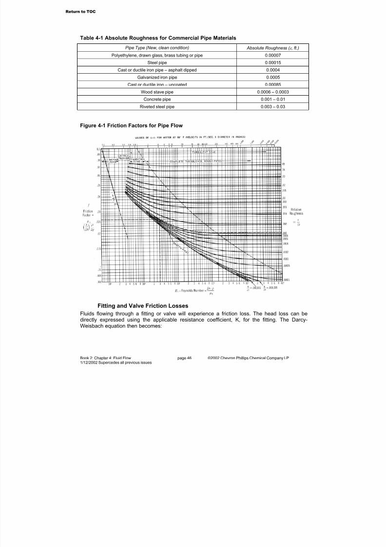
7/23/2019 The Performance Pipe Engineering Manual
http://slidepdf.com/reader/full/the-performance-pipe-engineering-manual 48/208
Book 2: Chapter 4: Fluid Flow page 46 ©2002 Chevron Phillips Chemical Company LP1/12/2002 Supercedes all previous issues
Table 4-1 Absolute Roughness for Commercial Pipe Materials
Pipe Type (New, clean condition) Absolute Roughness ( ε , ft.)
Polyethylene, drawn glass, brass tubing or pipe 0.00007
Steel pipe 0.00015
Cast or ductile iron pipe – asphalt dipped 0.0004
Galvanized iron pipe 0.0005
Cast or ductile iron – uncoated 0.00085
Wood stave pipe 0.0006 – 0.0003
Concrete pipe 0.001 – 0.01
Riveted steel pipe 0.003 – 0.03
Figure 4-1 Friction Factors for Pipe Flow
Fitting and Valve Friction Losses
Fluids flowing through a fitting or valve will experience a friction loss. The head loss can bedirectly expressed using the applicable resistance coefficient, K, for the fitting. The Darcy-Weisbach equation then becomes:
Return to TOC

7/23/2019 The Performance Pipe Engineering Manual
http://slidepdf.com/reader/full/the-performance-pipe-engineering-manual 49/208
Book 2: Chapter 4: Fluid Flow page 47 ©2002 Chevron Phillips Chemical Company LP1/12/2002 Supercedes all previous issues
=
g
V K hf
2
2
(4-11)
where
D
L
f K = (4-12)
Rearranging Formula 4-12 allows the fitting head loss to be expressed as feet of straight pipehaving the same head loss as the fitting.
f
KDL =
where
T f K K '=
so,
f
Df K L T '=
with fully turbulent flow,
f f T ≈
yielding,
DK L '= (4-13)
Table 4-2 presents K´ factors for various fittings.
Table 4-2 Fitting Coefficient K'
Fitting K’ Fitting K’
90° molded elbow 30 60° fabricated elbow 16
45° molded elbow 16 67.5° fabricated elbow 18
15° fabricated elbow 4 75° fabricated elbow 20
22.5° fabricated elbow 6 90° fabricated elbow 24
30° fabricated elbow 8 Equal outlet tee, run/branch 60
45° fabricated elbow 12 Equal outlet tee, run/run 20
Hazen-Williams
The Darcy-Weisbach/Colebrook/Moody method applies to non-plastic liquids, but it is complex.For some applications, empirical formulas are available, and when used within their limitations,reliable results can be obtained with greater convenience. Hazen and Williams developed anempirical formula for water.
The Hazen-Williams formula for water at 60° F can be applied to liquids having the same
kinematic viscosity of 1.130 centistokes (0.00001211 ft2/sec), or 31.5 SSU. Water’s viscosity
Return to TOC
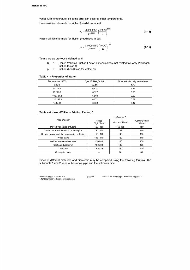
7/23/2019 The Performance Pipe Engineering Manual
http://slidepdf.com/reader/full/the-performance-pipe-engineering-manual 50/208
Book 2: Chapter 4: Fluid Flow page 48 ©2002 Chevron Phillips Chemical Company LP1/12/2002 Supercedes all previous issues
varies with temperature, so some error can occur at other temperatures.
Hazen-Williams formula for friction (head) loss in feet:
85.1
8655.4
100002083.0
=
C
Q
d
Lhf (4-14)
Hazen-Williams formula for friction (head) loss in psi:
85.1
8655.4
1000009015.0
=
C
Q
d
L pf (4-15)
Terms are as previously defined, and:
C = Hazen-Williams Friction Factor, dimensionless (not related to Darcy-Weisbachfriction factor, f)
pf = friction (head) loss for water, psi
Table 4-3 Properties of Water
Temperature, °F/°C Specific Weight, lb/ft 3
Kinematic Viscosity, centistokes
32 / 0 62.414 1.79
60 / 15.6 62.37 1.13
75 / 23.9 62.27 0.90
100 / 37.8 62.00 0.69
120 / 48.9 61.71 0.57
140 / 60 61.38 0.47
Table 4-4 Hazen-Williams Friction Factor, C
Values for C
Pipe Material RangeHigh / Low
Average ValueTypical Design
Value
Polyethylene pipe or tubing 160 / 150 150-155 150
Cement or mastic lined iron or steel pipe 160 / 130 148 140
Copper, brass, lead, tin or glass pipe or tubing 150 / 120 140 130
Wood stave 145 / 110 120 110
Welded and seamless steel 150 / 80 130 100
Cast and ductile iron 150 / 80 130 100Concrete 152 / 85 120 100
Corrugated steel – 60 60
Pipes of different materials and diameters may be compared using the following formula. Thesubscripts 1 and 2 refer to the known pipe and the unknown pipe.
Return to TOC
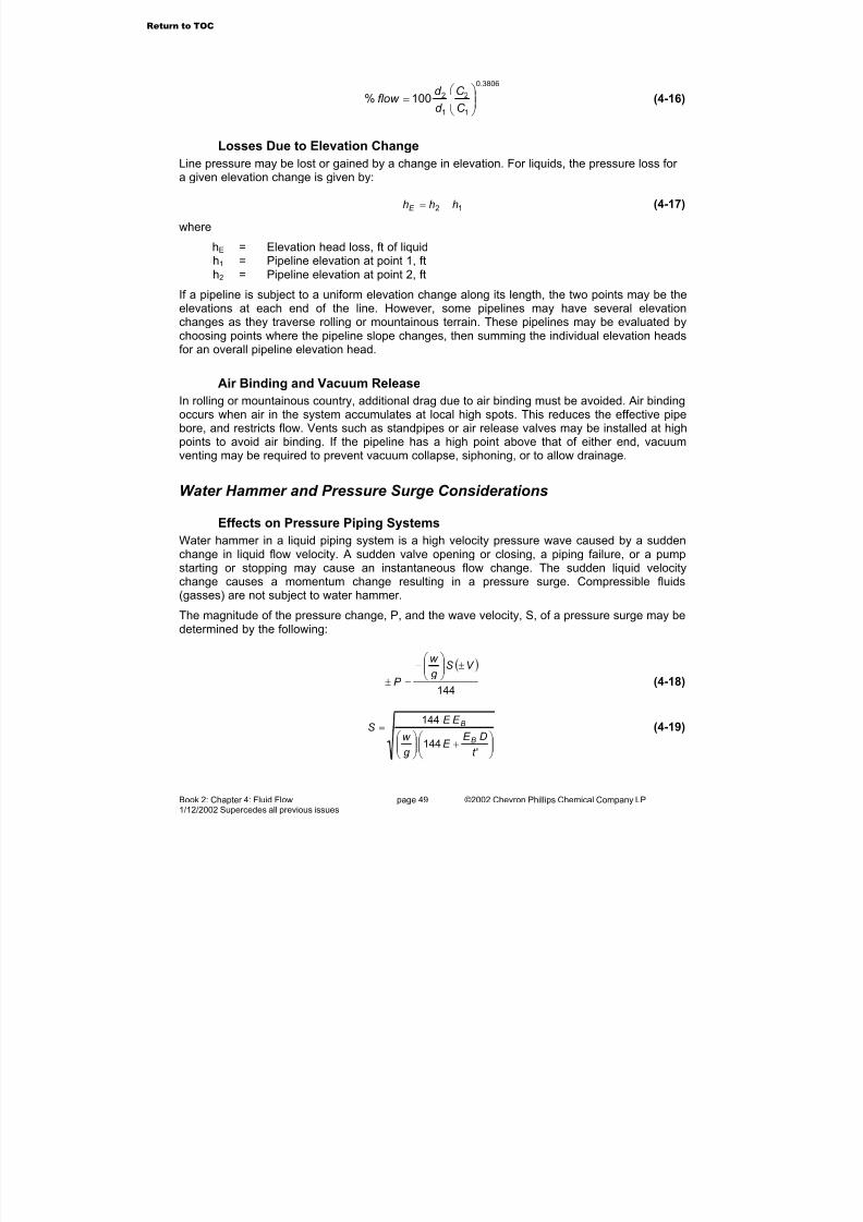
7/23/2019 The Performance Pipe Engineering Manual
http://slidepdf.com/reader/full/the-performance-pipe-engineering-manual 51/208
Book 2: Chapter 4: Fluid Flow page 49 ©2002 Chevron Phillips Chemical Company LP1/12/2002 Supercedes all previous issues
3806.0
1
2
1
2100%
=
C
C
d
d flow (4-16)
Losses Due to Elevation Change
Line pressure may be lost or gained by a change in elevation. For liquids, the pressure loss for a given elevation change is given by:
12 hhhE −= (4-17)
where
hE = Elevation head loss, ft of liquidh1 = Pipeline elevation at point 1, fth2 = Pipeline elevation at point 2, ft
If a pipeline is subject to a uniform elevation change along its length, the two points may be theelevations at each end of the line. However, some pipelines may have several elevationchanges as they traverse rolling or mountainous terrain. These pipelines may be evaluated bychoosing points where the pipeline slope changes, then summing the individual elevation headsfor an overall pipeline elevation head.
Air Binding and Vacuum Release
In rolling or mountainous country, additional drag due to air binding must be avoided. Air bindingoccurs when air in the system accumulates at local high spots. This reduces the effective pipebore, and restricts flow. Vents such as standpipes or air release valves may be installed at highpoints to avoid air binding. If the pipeline has a high point above that of either end, vacuumventing may be required to prevent vacuum collapse, siphoning, or to allow drainage.
Water Hammer and Pressure Surge Considerations
Effects on Pressure Piping Systems
Water hammer in a liquid piping system is a high velocity pressure wave caused by a suddenchange in liquid flow velocity. A sudden valve opening or closing, a piping failure, or a pumpstarting or stopping may cause an instantaneous flow change. The sudden liquid velocitychange causes a momentum change resulting in a pressure surge. Compressible fluids(gasses) are not subject to water hammer.
The magnitude of the pressure change, P, and the wave velocity, S, of a pressure surge may bedetermined by the following:
( )
144
V Sg w
P
±
−
=± (4-18)
+
=
'144
144
t
DE E
g
w
E E S
B
B (4-19)
Return to TOC

7/23/2019 The Performance Pipe Engineering Manual
http://slidepdf.com/reader/full/the-performance-pipe-engineering-manual 52/208
Book 2: Chapter 4: Fluid Flow page 50 ©2002 Chevron Phillips Chemical Company LP1/12/2002 Supercedes all previous issues
where
±P = pressure change, psiw = liquid weight, lb/ft3 g = acceleration of gravity, ft/sec2 S = wave velocity, ft/sec
±V = liquid velocity change, ft/secE = short-term pipe elastic modulus, psiEB = liquid bulk modulus, lb/ft2 D = pipe inside diameter, ftt’ = pipe wall thickness, ft
The pressure wave is superimposed on the system, and may be negative or positive. Water hammer analysis of piping systems is complex and depends on pumping characteristics,elevation changes, valve actuation, system geometry, dissolved gasses, and other factors. For a detailed analysis of hydraulic surge in piping systems, a professional design engineer or consultant who is experienced with hydraulic surge in piping systems should be consulted.
Equation 4-18 gives the maximum surge pressure for a given velocity change. Typically for a
rapid valve closure the velocity change equals the flow velocity in the line. However, eventssuch as cavitation or water column separation can occur during which the water velocity canexceed the average flow velocity.
Surge Allowance
Flexibility and short-term mechanical strength in DRISCOPLEX™ polyethylene pressure pipeprovide exceptional surge tolerance. The low elastic modulus provides a quick dampeningmechanism for shock loads. These properties result in lower surge pressures compared to morerigid systems such as steel, ductile iron, or PVC. For the same liquid and velocity change, surgepressures in polyethylene pipe are about 86% less than in steel pipe, about 80% less than inductile iron pipe, and about 50% less than in PVC pipe.
Surges affect systems differently depending upon the system design, surge pressure magnitudeand surge frequency. Allowable surge pressures may be limited by the pressure ratings of pumps, valves, fittings, partially restrained or non-restrained connections, or other appurtenances.
Water systems may be subject to surge pressures when there is a sudden increase or decreasein flow velocity. Recurrent pressure surges, P RS, are repetitive surge events that occur frequently such as during pump start-stop operation. Occasional pressure surges, P OS, areirregularly occurring surges such as a sudden flow change due to firefighting or check valveoperation. Surge pressure corresponds directly to velocity change, that is, greater velocitychange produces greater surge pressure.
With its unique ductile elastic properties and superb fatigue resistance, DRISCOPLEX™
polyethylene pipe is especially tolerant of pressure surges. Unlike other plastic and metal pipes,the allowance for pressure surge is applied above the pressure rating of the pipe. In Table 4-5,pressure rating, P, is determined using Formula 3-1.
Table 4-5 Pressure Surge Allowance
Type of Pressure Surge Allowance for Surge
Recurrent Surge, P RS P RS = 0.5 (P)
Occasional Surge, P OS P OS = 1.0 (P)
Return to TOC
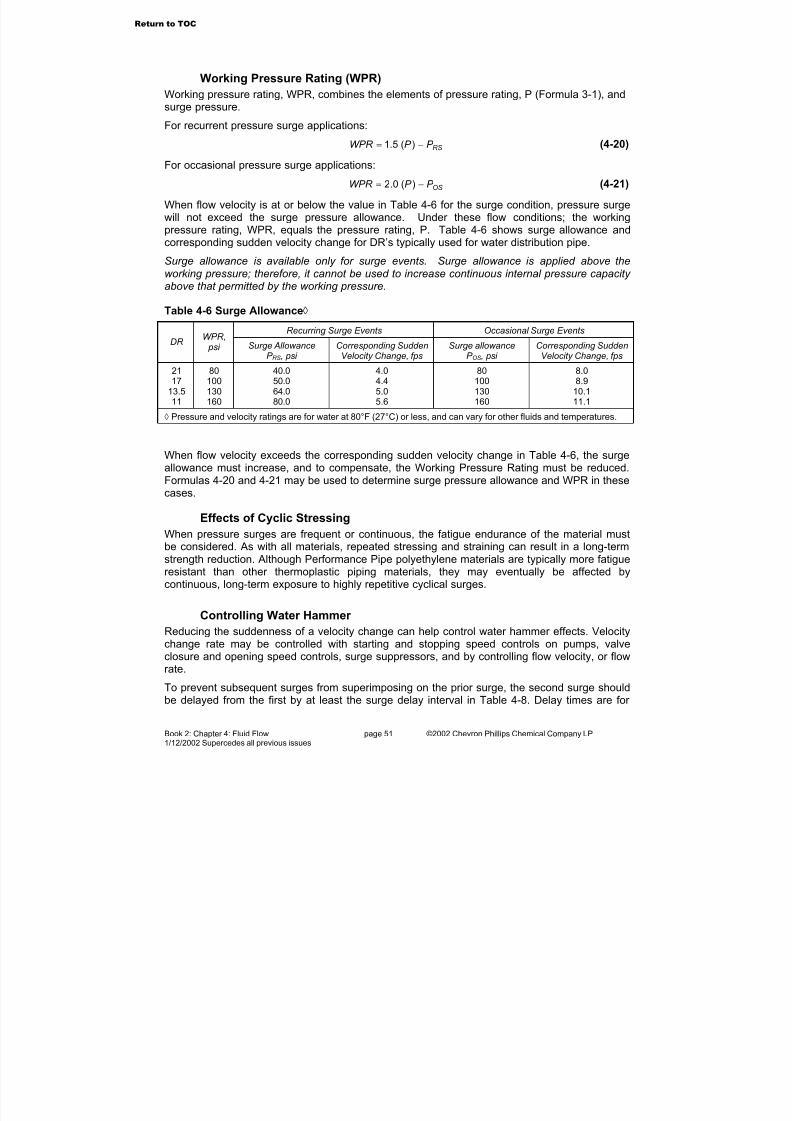
7/23/2019 The Performance Pipe Engineering Manual
http://slidepdf.com/reader/full/the-performance-pipe-engineering-manual 53/208
Book 2: Chapter 4: Fluid Flow page 51 ©2002 Chevron Phillips Chemical Company LP1/12/2002 Supercedes all previous issues
Working Pressure Rating (WPR)
Working pressure rating, WPR, combines the elements of pressure rating, P (Formula 3-1), andsurge pressure.
For recurrent pressure surge applications:
RS
P P WPR −= )(5.1 (4-20)
For occasional pressure surge applications:
OSP P WPR −= )(0.2 (4-21)
When flow velocity is at or below the value in Table 4-6 for the surge condition, pressure surgewill not exceed the surge pressure allowance. Under these flow conditions; the workingpressure rating, WPR, equals the pressure rating, P. Table 4-6 shows surge allowance andcorresponding sudden velocity change for DR’s typically used for water distribution pipe.
Surge allowance is available only for surge events. Surge allowance is applied above theworking pressure; therefore, it cannot be used to increase continuous internal pressure capacity above that permitted by the working pressure.
Table 4-6 Surge Allowance◊
Recurring Surge Events Occasional Surge Events
DR WPR, psi Surge Allowance
P RS, psi Corresponding SuddenVelocity Change, fps
Surge allowanceP OS, psi
Corresponding SuddenVelocity Change, fps
2117
13.511
80100130160
40.050.064.080.0
4.04.45.05.6
80100130160
8.08.9
10.111.1
◊ Pressure and velocity ratings are for water at 80°F (27°C) or less, and can vary for other fluids and temperatures.
When flow velocity exceeds the corresponding sudden velocity change in Table 4-6, the surgeallowance must increase, and to compensate, the Working Pressure Rating must be reduced.Formulas 4-20 and 4-21 may be used to determine surge pressure allowance and WPR in thesecases.
Effects of Cyclic Stressing
When pressure surges are frequent or continuous, the fatigue endurance of the material mustbe considered. As with all materials, repeated stressing and straining can result in a long-termstrength reduction. Although Performance Pipe polyethylene materials are typically more fatigueresistant than other thermoplastic piping materials, they may eventually be affected bycontinuous, long-term exposure to highly repetitive cyclical surges.
Controlling Water Hammer
Reducing the suddenness of a velocity change can help control water hammer effects. Velocitychange rate may be controlled with starting and stopping speed controls on pumps, valveclosure and opening speed controls, surge suppressors, and by controlling flow velocity, or flowrate.
To prevent subsequent surges from superimposing on the prior surge, the second surge shouldbe delayed from the first by at least the surge delay interval in Table 4-8. Delay times are for
Return to TOC
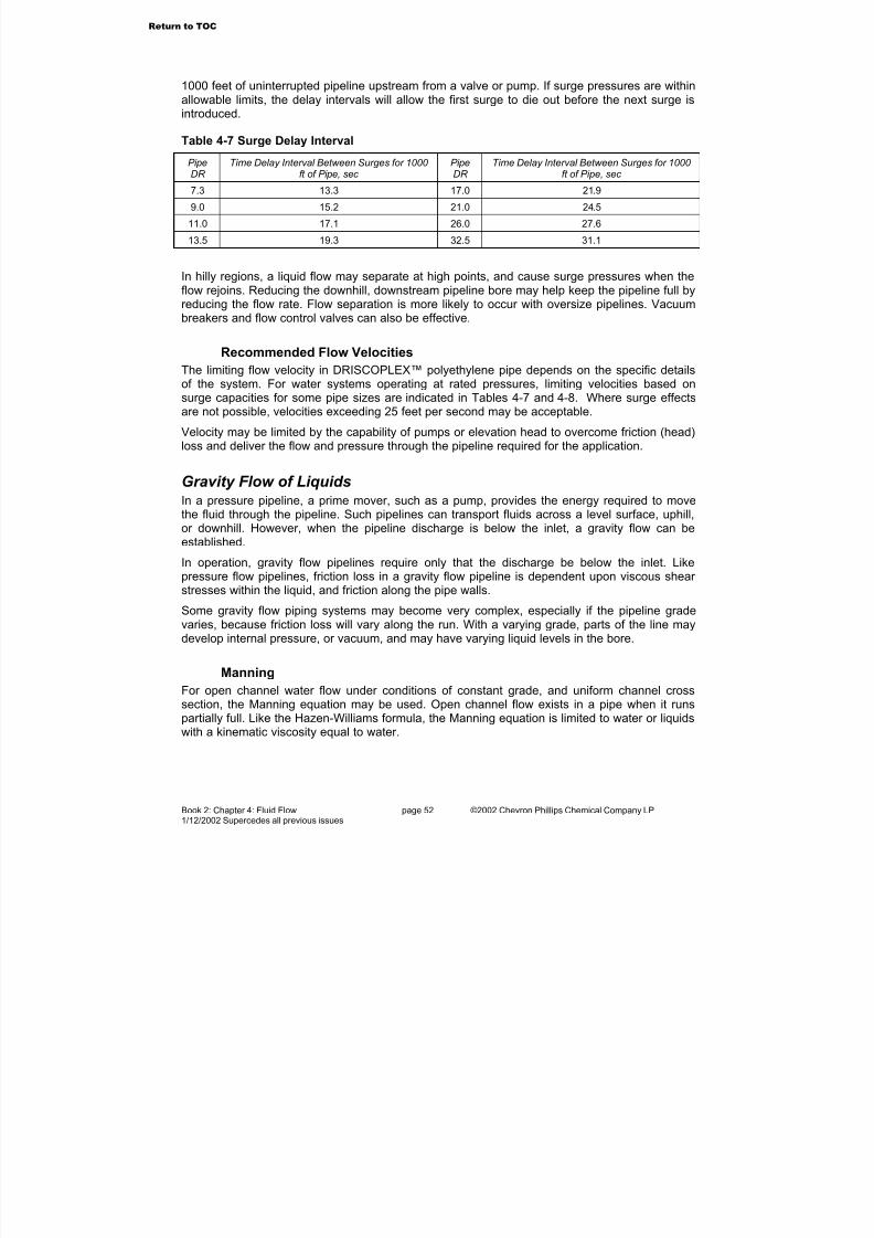
7/23/2019 The Performance Pipe Engineering Manual
http://slidepdf.com/reader/full/the-performance-pipe-engineering-manual 54/208
Book 2: Chapter 4: Fluid Flow page 52 ©2002 Chevron Phillips Chemical Company LP1/12/2002 Supercedes all previous issues
1000 feet of uninterrupted pipeline upstream from a valve or pump. If surge pressures are withinallowable limits, the delay intervals will allow the first surge to die out before the next surge isintroduced.
Table 4-7 Surge Delay Interval
PipeDR Time Delay Interval Between Surges for 1000 ft of Pipe, sec PipeDR Time Delay Interval Between Surges for 1000 ft of Pipe, sec
7.3 13.3 17.0 21.9
9.0 15.2 21.0 24.5
11.0 17.1 26.0 27.6
13.5 19.3 32.5 31.1
In hilly regions, a liquid flow may separate at high points, and cause surge pressures when theflow rejoins. Reducing the downhill, downstream pipeline bore may help keep the pipeline full byreducing the flow rate. Flow separation is more likely to occur with oversize pipelines. Vacuumbreakers and flow control valves can also be effective.
Recommended Flow Velocities
The limiting flow velocity in DRISCOPLEX™ polyethylene pipe depends on the specific detailsof the system. For water systems operating at rated pressures, limiting velocities based onsurge capacities for some pipe sizes are indicated in Tables 4-7 and 4-8. Where surge effectsare not possible, velocities exceeding 25 feet per second may be acceptable.
Velocity may be limited by the capability of pumps or elevation head to overcome friction (head)loss and deliver the flow and pressure through the pipeline required for the application.
Gravity Flow of Liquids
In a pressure pipeline, a prime mover, such as a pump, provides the energy required to movethe fluid through the pipeline. Such pipelines can transport fluids across a level surface, uphill,or downhill. However, when the pipeline discharge is below the inlet, a gravity flow can beestablished.
In operation, gravity flow pipelines require only that the discharge be below the inlet. Likepressure flow pipelines, friction loss in a gravity flow pipeline is dependent upon viscous shear stresses within the liquid, and friction along the pipe walls.
Some gravity flow piping systems may become very complex, especially if the pipeline gradevaries, because friction loss will vary along the run. With a varying grade, parts of the line maydevelop internal pressure, or vacuum, and may have varying liquid levels in the bore.
ManningFor open channel water flow under conditions of constant grade, and uniform channel crosssection, the Manning equation may be used. Open channel flow exists in a pipe when it runspartially full. Like the Hazen-Williams formula, the Manning equation is limited to water or liquidswith a kinematic viscosity equal to water.
Return to TOC

7/23/2019 The Performance Pipe Engineering Manual
http://slidepdf.com/reader/full/the-performance-pipe-engineering-manual 55/208
Book 2: Chapter 4: Fluid Flow page 53 ©2002 Chevron Phillips Chemical Company LP1/12/2002 Supercedes all previous issues
Manning Equation
2/13/2486.1Sr
nV = (4-22)
where
V = flow velocity, ft/secn = roughness coefficient, dimensionlessr = hydraulic radius, ft
P
Ar = (4-23)
A = channel cross section area, ft2 P = perimeter wetted by flow, ftS = hydraulic slope, ft/ft
L
h
L
hhS f =
−= 21 (4-24)
h1 = upstream pipe elevation, fth2 = downstream pipe elevation, fthf = friction (head) loss, ft of liquid
It is convenient to combine the Manning equation with
AV Q = (4-25)
to obtain
2/13/2486.1 Sr n
AQ = (4-26)
where terms are as defined above, and
Q = flow, ft3/sec
When a circular pipe is running full or half-full,
484
d Dr == (4-27)
where
D = pipe bore, ftd = pipe bore, in
Full pipe flow in ft3 per second may be estimated using:
( )n
Sd Q
2/13/8410136.6 −×= (4-28)
Return to TOC
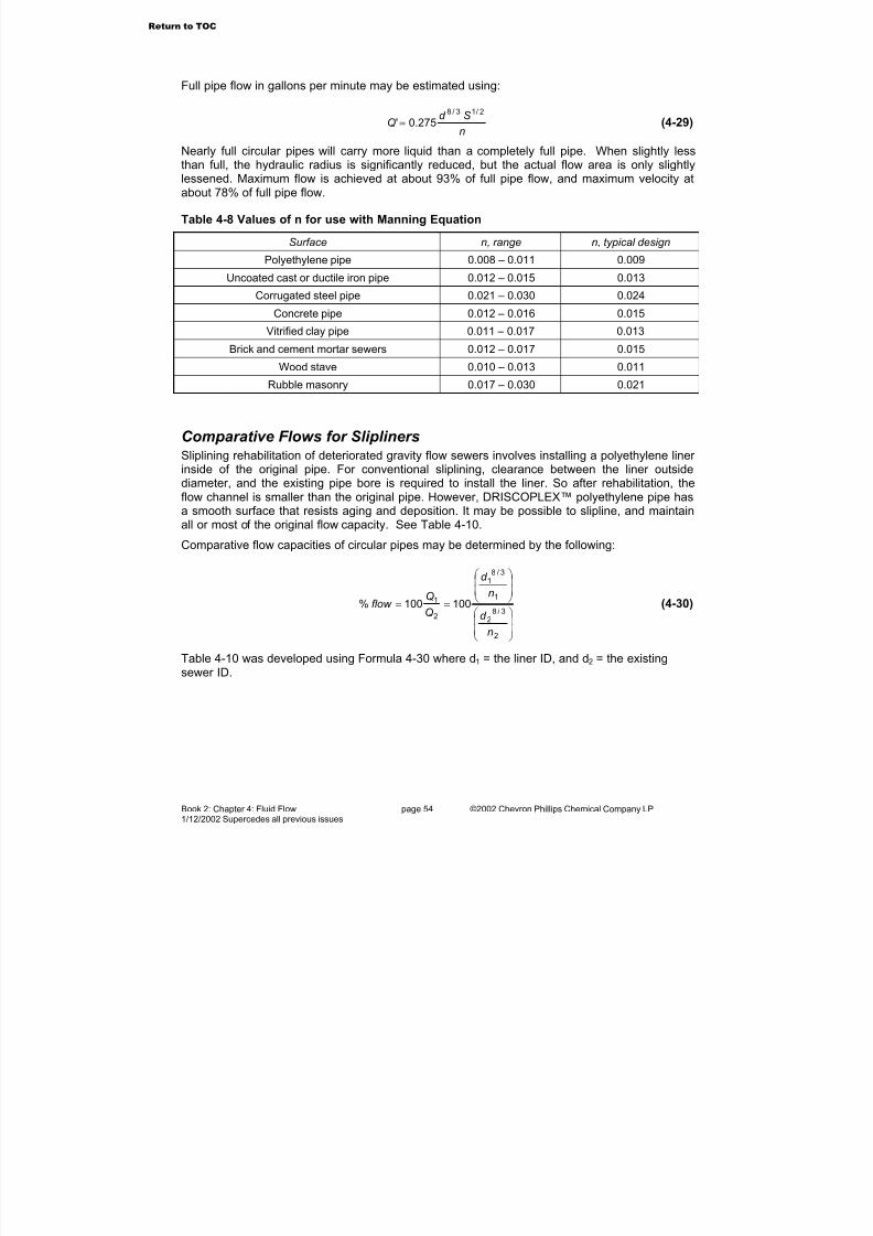
7/23/2019 The Performance Pipe Engineering Manual
http://slidepdf.com/reader/full/the-performance-pipe-engineering-manual 56/208
Book 2: Chapter 4: Fluid Flow page 54 ©2002 Chevron Phillips Chemical Company LP1/12/2002 Supercedes all previous issues
Full pipe flow in gallons per minute may be estimated using:
n
Sd Q
2/13/8
275.0'= (4-29)
Nearly full circular pipes will carry more liquid than a completely full pipe. When slightly less
than full, the hydraulic radius is significantly reduced, but the actual flow area is only slightlylessened. Maximum flow is achieved at about 93% of full pipe flow, and maximum velocity atabout 78% of full pipe flow.
Table 4-8 Values of n for use with Manning Equation
Surface n, range n, typical design
Polyethylene pipe 0.008 – 0.011 0.009
Uncoated cast or ductile iron pipe 0.012 – 0.015 0.013
Corrugated steel pipe 0.021 – 0.030 0.024
Concrete pipe 0.012 – 0.016 0.015
Vitrified clay pipe 0.011 – 0.017 0.013Brick and cement mortar sewers 0.012 – 0.017 0.015
Wood stave 0.010 – 0.013 0.011
Rubble masonry 0.017 – 0.030 0.021
Comparative Flows for SliplinersSliplining rehabilitation of deteriorated gravity flow sewers involves installing a polyethylene liner inside of the original pipe. For conventional sliplining, clearance between the liner outsidediameter, and the existing pipe bore is required to install the liner. So after rehabilitation, the
flow channel is smaller than the original pipe. However, DRISCOPLEX™ polyethylene pipe hasa smooth surface that resists aging and deposition. It may be possible to slipline, and maintainall or most of the original flow capacity. See Table 4-10.
Comparative flow capacities of circular pipes may be determined by the following:
==
2
3/82
1
3/81
2
1 100100%
n
d
n
d
Q
Qflow (4-30)
Table 4-10 was developed using Formula 4-30 where d1 = the liner ID, and d2 = the existing
sewer ID.
Return to TOC
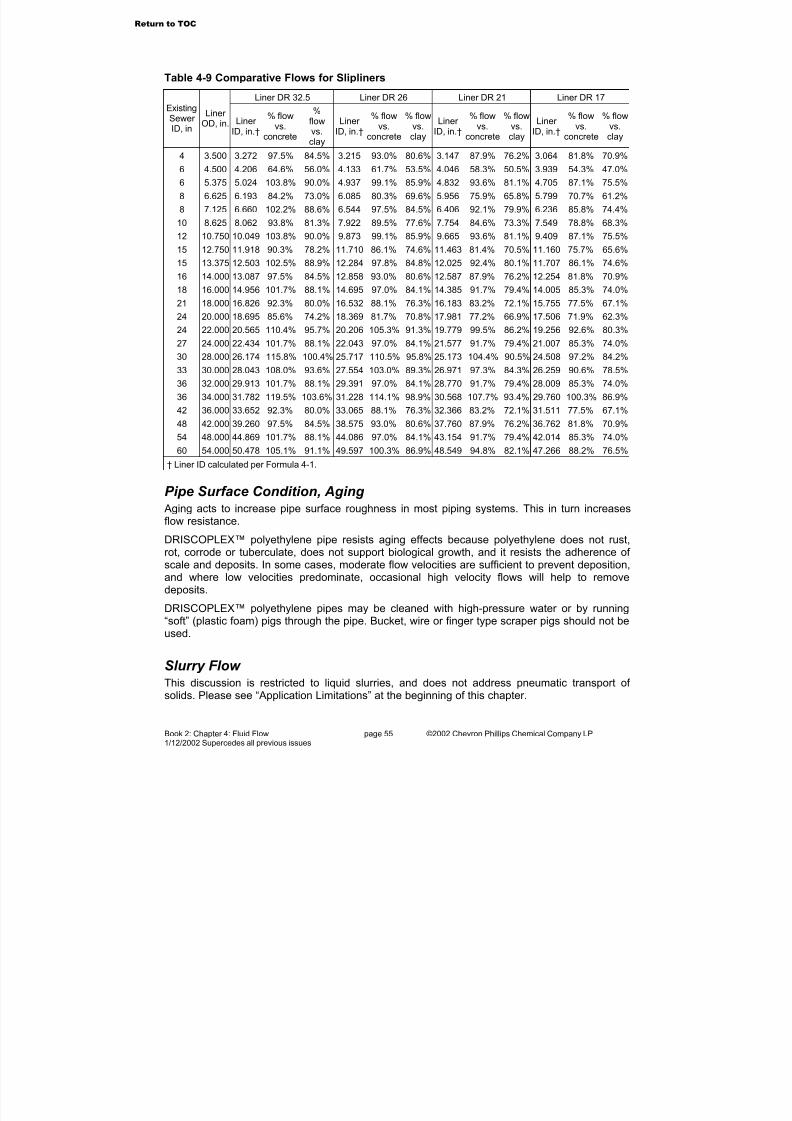
7/23/2019 The Performance Pipe Engineering Manual
http://slidepdf.com/reader/full/the-performance-pipe-engineering-manual 57/208
Book 2: Chapter 4: Fluid Flow page 55 ©2002 Chevron Phillips Chemical Company LP1/12/2002 Supercedes all previous issues
Table 4-9 Comparative Flows for Slipliners
Liner DR 32.5 Liner DR 26 Liner DR 21 Liner DR 17
ExistingSewer ID, in
Liner OD, in. Liner
ID, in.†
% flowvs.
concrete
%flowvs.clay
Liner ID, in.†
% flowvs.
concrete
% flowvs.clay
Liner ID, in.†
% flowvs.
concrete
% flowvs.clay
Liner ID, in.†
% flowvs.
concrete
% flowvs.clay
4 3.500 3.272 97.5% 84.5% 3.215 93.0% 80.6% 3.147 87.9% 76.2% 3.064 81.8% 70.9%
6 4.500 4.206 64.6% 56.0% 4.133 61.7% 53.5% 4.046 58.3% 50.5% 3.939 54.3% 47.0%
6 5.375 5.024 103.8% 90.0% 4.937 99.1% 85.9% 4.832 93.6% 81.1% 4.705 87.1% 75.5%
8 6.625 6.193 84.2% 73.0% 6.085 80.3% 69.6% 5.956 75.9% 65.8% 5.799 70.7% 61.2%
8 7.125 6.660 102.2% 88.6% 6.544 97.5% 84.5% 6.406 92.1% 79.9% 6.236 85.8% 74.4%
10 8.625 8.062 93.8% 81.3% 7.922 89.5% 77.6% 7.754 84.6% 73.3% 7.549 78.8% 68.3%
12 10.750 10.049 103.8% 90.0% 9.873 99.1% 85.9% 9.665 93.6% 81.1% 9.409 87.1% 75.5%
15 12.750 11.918 90.3% 78.2% 11.710 86.1% 74.6% 11.463 81.4% 70.5% 11.160 75.7% 65.6%
15 13.375 12.503 102.5% 88.9% 12.284 97.8% 84.8% 12.025 92.4% 80.1% 11.707 86.1% 74.6%
16 14.000 13.087 97.5% 84.5% 12.858 93.0% 80.6% 12.587 87.9% 76.2% 12.254 81.8% 70.9%
18 16.000 14.956 101.7% 88.1% 14.695 97.0% 84.1% 14.385 91.7% 79.4% 14.005 85.3% 74.0%
21 18.000 16.826 92.3% 80.0% 16.532 88.1% 76.3% 16.183 83.2% 72.1% 15.755 77.5% 67.1%24 20.000 18.695 85.6% 74.2% 18.369 81.7% 70.8% 17.981 77.2% 66.9% 17.506 71.9% 62.3%
24 22.000 20.565 110.4% 95.7% 20.206 105.3% 91.3% 19.779 99.5% 86.2% 19.256 92.6% 80.3%
27 24.000 22.434 101.7% 88.1% 22.043 97.0% 84.1% 21.577 91.7% 79.4% 21.007 85.3% 74.0%
30 28.000 26.174 115.8% 100.4% 25.717 110.5% 95.8% 25.173 104.4% 90.5% 24.508 97.2% 84.2%
33 30.000 28.043 108.0% 93.6% 27.554 103.0% 89.3% 26.971 97.3% 84.3% 26.259 90.6% 78.5%
36 32.000 29.913 101.7% 88.1% 29.391 97.0% 84.1% 28.770 91.7% 79.4% 28.009 85.3% 74.0%
36 34.000 31.782 119.5% 103.6% 31.228 114.1% 98.9% 30.568 107.7% 93.4% 29.760 100.3% 86.9%
42 36.000 33.652 92.3% 80.0% 33.065 88.1% 76.3% 32.366 83.2% 72.1% 31.511 77.5% 67.1%
48 42.000 39.260 97.5% 84.5% 38.575 93.0% 80.6% 37.760 87.9% 76.2% 36.762 81.8% 70.9%
54 48.000 44.869 101.7% 88.1% 44.086 97.0% 84.1% 43.154 91.7% 79.4% 42.014 85.3% 74.0%
60 54.000 50.478 105.1% 91.1% 49.597 100.3% 86.9% 48.549 94.8% 82.1% 47.266 88.2% 76.5%† Liner ID calculated per Formula 4-1.
Pipe Surface Condition, Aging Aging acts to increase pipe surface roughness in most piping systems. This in turn increasesflow resistance.
DRISCOPLEX™ polyethylene pipe resists aging effects because polyethylene does not rust,rot, corrode or tuberculate, does not support biological growth, and it resists the adherence of scale and deposits. In some cases, moderate flow velocities are sufficient to prevent deposition,and where low velocities predominate, occasional high velocity flows will help to removedeposits.
DRISCOPLEX™ polyethylene pipes may be cleaned with high-pressure water or by running“soft” (plastic foam) pigs through the pipe. Bucket, wire or finger type scraper pigs should not beused.
Slurry Flow This discussion is restricted to liquid slurries, and does not address pneumatic transport of solids. Please see “Application Limitations” at the beginning of this chapter.
Return to TOC
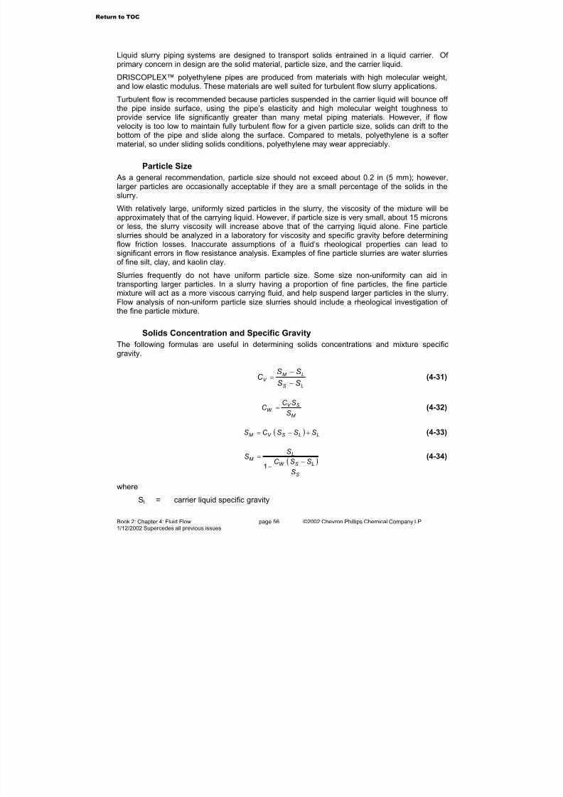
7/23/2019 The Performance Pipe Engineering Manual
http://slidepdf.com/reader/full/the-performance-pipe-engineering-manual 58/208
Book 2: Chapter 4: Fluid Flow page 56 ©2002 Chevron Phillips Chemical Company LP1/12/2002 Supercedes all previous issues
Liquid slurry piping systems are designed to transport solids entrained in a liquid carrier. Of primary concern in design are the solid material, particle size, and the carrier liquid.
DRISCOPLEX™ polyethylene pipes are produced from materials with high molecular weight,and low elastic modulus. These materials are well suited for turbulent flow slurry applications.
Turbulent flow is recommended because particles suspended in the carrier liquid will bounce off
the pipe inside surface, using the pipe’s elasticity and high molecular weight toughness toprovide service life significantly greater than many metal piping materials. However, if flowvelocity is too low to maintain fully turbulent flow for a given particle size, solids can drift to thebottom of the pipe and slide along the surface. Compared to metals, polyethylene is a softer material, so under sliding solids conditions, polyethylene may wear appreciably.
Particle Size
As a general recommendation, particle size should not exceed about 0.2 in (5 mm); however,larger particles are occasionally acceptable if they are a small percentage of the solids in theslurry.
With relatively large, uniformly sized particles in the slurry, the viscosity of the mixture will be
approximately that of the carrying liquid. However, if particle size is very small, about 15 micronsor less, the slurry viscosity will increase above that of the carrying liquid alone. Fine particleslurries should be analyzed in a laboratory for viscosity and specific gravity before determiningflow friction losses. Inaccurate assumptions of a fluid’s rheological properties can lead tosignificant errors in flow resistance analysis. Examples of fine particle slurries are water slurriesof fine silt, clay, and kaolin clay.
Slurries frequently do not have uniform particle size. Some size non-uniformity can aid intransporting larger particles. In a slurry having a proportion of fine particles, the fine particlemixture will act as a more viscous carrying fluid, and help suspend larger particles in the slurry.Flow analysis of non-uniform particle size slurries should include a rheological investigation of the fine particle mixture.
Solids Concentration and Specific Gravity
The following formulas are useful in determining solids concentrations and mixture specificgravity.
LS
LM V
SS
SSC
−
−= (4-31)
M
SV W
S
SC C = (4-32)
( ) LLSV M SSSC S +−= (4-33)
( )
S
LSW
LM
S
SSC
SS
−−
=1
(4-34)
where
SL = carrier liquid specific gravity
Return to TOC

7/23/2019 The Performance Pipe Engineering Manual
http://slidepdf.com/reader/full/the-performance-pipe-engineering-manual 59/208
Book 2: Chapter 4: Fluid Flow page 57 ©2002 Chevron Phillips Chemical Company LP1/12/2002 Supercedes all previous issues
SS = solids specific gravitySM = slurry mixture specific gravityCV = percent solids concentration by volumeCW = percent solids concentration by weight
Critical Velocity As presented above, turbulent flow is recommended to keep particles in suspension. Turbulentflow avoids the formation of a sliding bed of solids, excessive pipeline wear, and possibleclogging. Generally, Reynolds numbers above 4000 will insure turbulent flow. See “PressureFlow of Liquids” at the beginning of this chapter.
A general recommendation is to maintain flow velocity at about 30% above the criticalsettlement velocity. A study performed by Durand on sand-water slurries provides the followingformula for determining critical velocity:
( )12 −= SLC Sgd F V (4-35)
where terms are as previously defined and
VC = critical carrying velocity, ft/secFL = coefficient dependent upon grain size and concentration. (Table 4-13 and
Table 4-14.)
A guideline minimum velocity recommendation for fine particle slurries (below 50 microns, 0.05mm) is 4 to 7 ft/sec, so long as turbulent flow is maintained. A guideline minimum velocity for larger particle slurries (over 150 microns, 0.15 mm) is
DV M 14= (4-36)
where
VM = approximate minimum velocity, ft/sec
Another useful relationship is that critical velocity changes with the pipe bore, that is, for thesame carrying liquid, particle size and solids concentration, critical velocity increases withincreasing pipe bore. Analysis of Formula 4-2, the Darcy-Weisbach formula shows the followingrelationship:
1
1
22 V
D
DV = (4-37)
where the subscripts 1 and 2 are for the two pipe diameters.
Return to TOC

7/23/2019 The Performance Pipe Engineering Manual
http://slidepdf.com/reader/full/the-performance-pipe-engineering-manual 60/208
Book 2: Chapter 4: Fluid Flow page 58 ©2002 Chevron Phillips Chemical Company LP1/12/2002 Supercedes all previous issues
Table 4-10 Scale of Particle Sizes
Tyler Screen Mesh U.S. Standard Mesh Inches Microns Class
1.3 – 2.5 33,000 – 63,500 Very coarse gravel
0.6 – 1.3 15,200 – 32,000 Coarse gravel
2.5 0.321 8,000 Medium gravel
5 5 0.157 4,000 Fine gravel
9 10 0.079 2,000 Very fine gravel
16 18 0.039 1,000 Very coarse sand
32 35 0.0197 500 Coarse sand
60 60 0.0098 250 Medium sand
115 120 0.0049 125 Fine sand
250 230 0.0024 62 Very fine sand
400 0.0015 37 Coarse silt
0.0006 – 0.0012 16 – 31 Medium silt
8 – 13 Fine silt
4 – 8 Very fine silt
2 – 4 Coarse clay
1 – 2 Medium clay
0.5 - 1 Fine clay
Table 4-11 Specific Gravity and Slurry Solids Concentration
Typical Solids ConcentrationMaterial Specific Gravity
% by Weight % by Volume
Gilsonite 1.05 40 – 45 39 – 44
Coal 1.40 45 – 55 37 – 47
Sand 2.65 43 – 43 23 – 30
Limestone 2.70 60 – 65 36 – 41
Copper Concentrate 4.30 60 – 65 26 – 30
Iron Ore 4.90
Iron Sands 1.90
Magnetite 4.90 60 - 65 23 - 27
Return to TOC

7/23/2019 The Performance Pipe Engineering Manual
http://slidepdf.com/reader/full/the-performance-pipe-engineering-manual 61/208
Book 2: Chapter 4: Fluid Flow page 59 ©2002 Chevron Phillips Chemical Company LP1/12/2002 Supercedes all previous issues
Table 4-12 Water-Base Slurry Specific Gravities
Solid Specific Gravity, SSC W
1.4 1.8 2.2 2.6 3.0 3.4 3.8 4.2 4.6 5.0
5 1.01 1.02 1.03 1.03 1.03 1.04 1.04 1.04 1.04 1.04
10 1.03 1.05 1.06 1.07 1.07 1.08 1.08 1.08 1.08 1.09
15 1.04 1.07 1.09 1.10 1.11 1.12 1.12 1.13 1.13 1.14
20 1.05 1.10 1.12 1.14 1.15 1.16 1.17 1.18 1.19 1.19
25 1.08 1.13 1.16 1.18 1.20 1.21 1.23 1.24 1.24 1.25
30 1.09 1.15 1.20 1.23 1.25 1.27 1.28 1.30 1.31 1.32
35 1.11 1.18 1.24 1.27 1.30 1.33 1.35 1.36 1.38 1.39
40 1.13 1.22 1.28 1.33 1.36 1.39 1.42 1.44 1.46 1.47
45 1.15 1.25 1.33 1.38 1.43 1.47 1.50 1.52 1.54 1.56
50 1.17 1.29 1.38 1.44 1.50 1.55 1.58 1.62 1.64 1.67
55 1.19 1.32 1.43 1.51 1.58 1.63 1.69 1.72 1.76 1.79
60 1.21 1.36 1.49 1.59 1.67 1.73 1.79 1.84 1.89 1.92
65 1.23 1.41 1.55 1.67 1.76 1.85 1.92 1.98 2.04 2.08
70 1.25 1.45 1.62 1.76 1.88 1.98 2.07 2.14 2.21 2.27
Table 4-13 Velocity Coefficient, FL (Uniform Particle Size)
Velocity Coefficient, F LParticle Size, mm
C V = 2% C V = 5% C V = 10% C V = 15%
.1 .76 0.92 0.94 0.96
.2 0.94 1.08 1.20 1.28
.4 1.08 1.26 1.41 1.46
.6 1.15 1.35 1.46 1.50
.8 1.21 1.39 1.45 1.48
1.0 1.24 1.04 1.42 1.44
1.2 1.27 1.38 1.40 1.40
1.4 1.29 1.36 1.67 1.37
1.6 1.30 1.35 1.35 1.35
1.8 1.32 1.34 1.34 1.34
2.0 1.33 1.34 1.34 1.34
2.2 1.34 1.34 1.34 1.34
2.4 1.34 1.34 1.34 1.34
2.6 1.35 1.35 1.35 1.35
2.8 1.36 1.36 1.36 1.36
≥ 3.0 1.36 1.36 1.36 1.36
Return to TOC
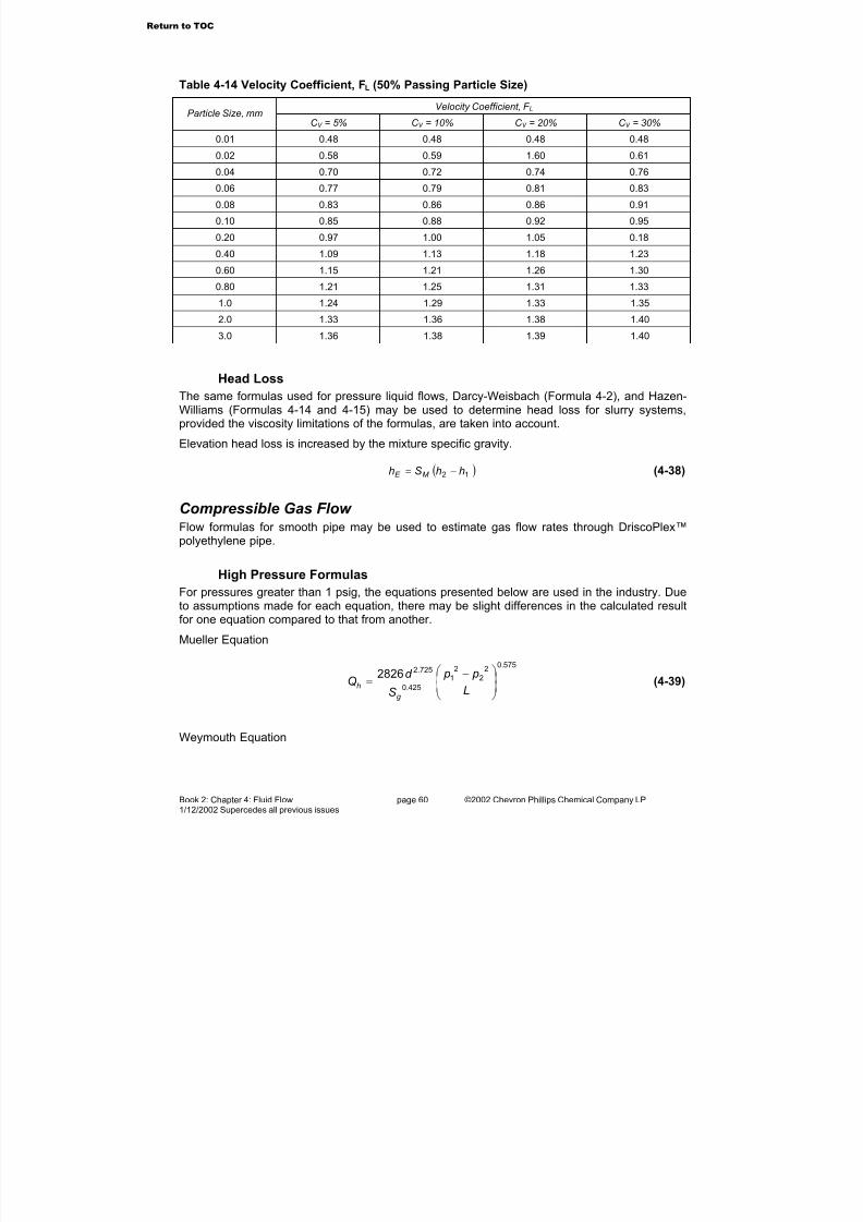
7/23/2019 The Performance Pipe Engineering Manual
http://slidepdf.com/reader/full/the-performance-pipe-engineering-manual 62/208
Book 2: Chapter 4: Fluid Flow page 60 ©2002 Chevron Phillips Chemical Company LP1/12/2002 Supercedes all previous issues
Table 4-14 Velocity Coefficient, FL (50% Passing Particle Size)
Velocity Coefficient, F L Particle Size, mm
C V = 5% C V = 10% C V = 20% C V = 30%
0.01 0.48 0.48 0.48 0.48
0.02 0.58 0.59 1.60 0.61
0.04 0.70 0.72 0.74 0.76
0.06 0.77 0.79 0.81 0.83
0.08 0.83 0.86 0.86 0.91
0.10 0.85 0.88 0.92 0.95
0.20 0.97 1.00 1.05 0.18
0.40 1.09 1.13 1.18 1.23
0.60 1.15 1.21 1.26 1.30
0.80 1.21 1.25 1.31 1.33
1.0 1.24 1.29 1.33 1.35
2.0 1.33 1.36 1.38 1.40
3.0 1.36 1.38 1.39 1.40
Head Loss
The same formulas used for pressure liquid flows, Darcy-Weisbach (Formula 4-2), and Hazen-Williams (Formulas 4-14 and 4-15) may be used to determine head loss for slurry systems,provided the viscosity limitations of the formulas, are taken into account.
Elevation head loss is increased by the mixture specific gravity.
( )12 hhSh M E −= (4-38)
Compressible Gas Flow Flow formulas for smooth pipe may be used to estimate gas flow rates through DriscoPlex™polyethylene pipe.
High Pressure Formulas
For pressures greater than 1 psig, the equations presented below are used in the industry. Dueto assumptions made for each equation, there may be slight differences in the calculated resultfor one equation compared to that from another.
Mueller Equation
575.02
2
2
1
425.0
725.22826
−=
L
p p
S
d Q
g
h (4-39)
Weymouth Equation
Return to TOC
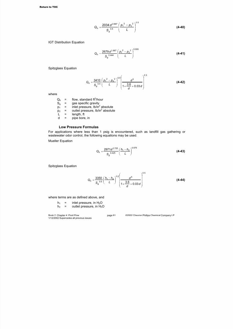
7/23/2019 The Performance Pipe Engineering Manual
http://slidepdf.com/reader/full/the-performance-pipe-engineering-manual 63/208
Book 2: Chapter 4: Fluid Flow page 61 ©2002 Chevron Phillips Chemical Company LP1/12/2002 Supercedes all previous issues
5.02
2
2
1
5.0
667.22034
−=
L
p p
S
d Q
g
h (4-40)
IGT Distribution Equation
555.02
22
1
444.0
667.22679
−=
L
p p
S
d Q
g
h (4-41)
Spitzglass Equation
5.0
55.0
22
21
5.0
03.06.3
1
3410
++
−=
d
d
d
L
p p
SQ
g
h (4-42)
where
Qh = flow, standard ft3/hour Sg = gas specific gravityp1 = inlet pressure, lb/in2 absolutep2 = outlet pressure, lb/in2 absoluteL = length, ftd = pipe bore, in
Low Pressure Formulas
For applications where less than 1 psig is encountered, such as landfill gas gathering or wastewater odor control, the following equations may be used.
Mueller Equation
575.0
21
425.0
725.22971
−=
L
hh
S
d Q
g
h (4-43)
Spitzglass Equation
5.0
55.0
21
5.0
03.06.3
1
3350
++
−=
d d
d L
hh
SQ
g
h (4-44)
where terms are as defined above, and
h1 = inlet pressure, in H2Oh2 = outlet pressure, in H2O
Return to TOC
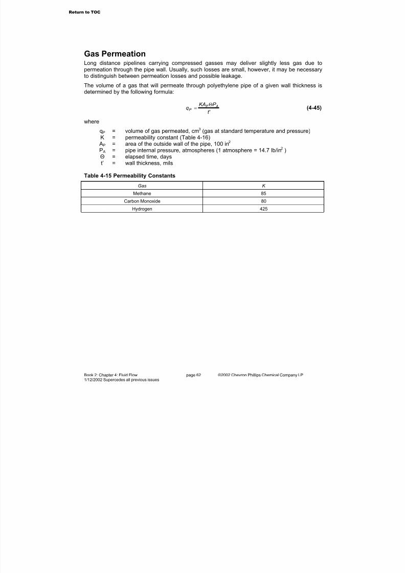
7/23/2019 The Performance Pipe Engineering Manual
http://slidepdf.com/reader/full/the-performance-pipe-engineering-manual 64/208
Book 2: Chapter 4: Fluid Flow page 62 ©2002 Chevron Phillips Chemical Company LP1/12/2002 Supercedes all previous issues
Gas PermeationLong distance pipelines carrying compressed gasses may deliver slightly less gas due topermeation through the pipe wall. Usually, such losses are small, however, it may be necessary
to distinguish between permeation losses and possible leakage.The volume of a gas that will permeate through polyethylene pipe of a given wall thickness isdetermined by the following formula:
't
P KAq AP
P
Θ= (4-45)
where
qP = volume of gas permeated, cm3 (gas at standard temperature and pressure)K = permeability constant (Table 4-16)
AP = area of the outside wall of the pipe, 100 in2 P A = pipe internal pressure, atmospheres (1 atmosphere = 14.7 lb/in2 )
Θ = elapsed time, dayst’ = wall thickness, mils
Table 4-15 Permeability Constants
Gas K
Methane 85
Carbon Monoxide 80
Hydrogen 425
Return to TOC

7/23/2019 The Performance Pipe Engineering Manual
http://slidepdf.com/reader/full/the-performance-pipe-engineering-manual 65/208
Book 2: Chapter 4: Fluid Flow page 63 ©2002 Chevron Phillips Chemical Company LP1/12/2002 Supercedes all previous issues
Table 4-16 Physical Properties of Gases (Approximate Values at 14.7 psi and 68°F)
GasChemical Formula
Molecular Weight
Weight Density, lb/ft 3,
σ Specific Gravity,
Sg
Acetylene (ethylene) C2H2 26.0 0.0682 0.907
Air – 29.0 0.0752 1.000
Ammonia NH3 17.0 0.0448 0.596
Argon A 39.9 0.1037 1.379
Butane C4H10 58.1 0.1554 2.067
Carbon Dioxide CO2 44.0 0.1150 1.529
Carbon Monoxide CO 28.0 0.0727 0.967
Ethane C2H6 30.0 0.0789 1.049
Ethylene C2H4 28.0 0.0733 0.975
Helium He 4.0 0.0104 0.138
Hydrogen Chloride HCl 36.5 0.0954 1.286
Hydrogen H 2.0 0.0052 0.070
Hydrogen Sulphide H2S 34.1 0.0895 1.190
Methane CH4 16.0 0.0417 0.554
Methyl Chloride CH3Cl 50.5 0.1342 1.785
Natural Gas – 19.5 0.0502 0.667
Nitric Oxide NO 30.0 0.0708 1.037
Nitrogen N2 28.0 0.0727 0.967
Nitrous Oxide N2O 44.0 0.1151 1.530
Oxygen O2 32.0 0.0831 1.105
Propane C3H8 44.1 0.1175 1.562
Propene (Propylene) C3H6 42.1 0.1091 1.451
Sulfur Dioxide SO2 64.1 0.1703 2.264
Landfill Gas (approx. value) – – – 1.00
Carbureted Water Gas – – – 0.63
Coal Gas – – – 0.42
Coke-Oven Gas – – – 0.44
Refinery Oil Gas – – – 0.99
Oil Gas (Pacific Coast) – – – 0.47
“Wet” Gas (approximatevalue)
– – – 0.75
Go to Chapter 5
Return to TOC
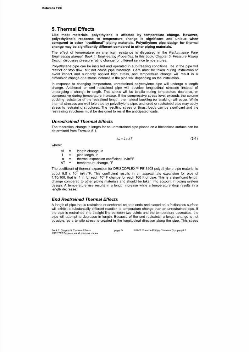
7/23/2019 The Performance Pipe Engineering Manual
http://slidepdf.com/reader/full/the-performance-pipe-engineering-manual 66/208
Book 2: Chapter 5: Thermal Effects page 64 ©2002 Chevron Phillips Chemical Company LP1/12/2002 Supercedes all previous issues
5. Thermal EffectsLike most materials, polyethylene is affected by temperature change. However,polyethylene’s response to temperature change is significant and unique whencompared to other “traditional” piping materials. Polyethylene pipe design for thermal
change may be significantly different compared to other piping materials.The effect of temperature on chemical resistance is discussed in the Performance PipeEngineering Manual, Book 1: Engineering Properties. In this book, Chapter 3, Pressure Rating Design discusses pressure rating change for different service temperatures.
Polyethylene pipe can be installed and operated in sub-freezing conditions. Ice in the pipe willrestrict or stop flow, but not cause pipe breakage. Care must be taken during installation toavoid impact and suddenly applied high stress, and temperature change will result in adimension change or a stress increase in the pipe wall depending on the installation.
In response to changing temperature, unrestrained polyethylene pipe will undergo a lengthchange. Anchored or end restrained pipe will develop longitudinal stresses instead of undergoing a change in length. This stress will be tensile during temperature decrease, or
compressive during temperature increase. If the compressive stress level exceeds the columnbuckling resistance of the restrained length, then lateral buckling (or snaking) will occur. Whilethermal stresses are well tolerated by polyethylene pipe, anchored or restrained pipe may applystress to restraining structures. The resulting stress or thrust loads can be significant and therestraining structures must be designed to resist the anticipated loads.
Unrestrained Thermal EffectsThe theoretical change in length for an unrestrained pipe placed on a frictionless surface can bedetermined from Formula 5-1.
T LL ∆=∆ α (5-1)
where:
∆L = length change, inL = pipe length, inα = thermal expansion coefficient, in/in/°F ∆T = temperature change, °F
The coefficient of thermal expansion for DRISCOPLEX™ PE 3408 polyethylene pipe material is
about 9.0 x 10⁻⁵
in/in/°F. This coefficient results in an approximate expansion for pipe of 1/10/100, that is, 1 in for each 10° F change for each 100 ft of pipe. This is a significant lengthchange compared to other piping materials and should be taken into account in piping systemdesign. A temperature rise results in a length increase while a temperature drop results in a
length decrease.
End Restrained Thermal Effects A length of pipe that is restrained or anchored on both ends and placed on a frictionless surfacewill exhibit a substantially different reaction to temperature change than an unrestrained pipe. If the pipe is restrained in a straight line between two points and the temperature decreases, thepipe will attempt to decrease in length. Because of the end restraints, a length change is notpossible, so a tensile stress is created in the longitudinal direction along the pipe. This stress
Return to TOC
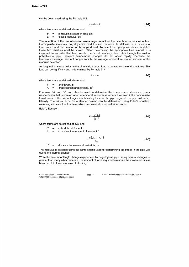
7/23/2019 The Performance Pipe Engineering Manual
http://slidepdf.com/reader/full/the-performance-pipe-engineering-manual 67/208
Book 2: Chapter 5: Thermal Effects page 65 ©2002 Chevron Phillips Chemical Company LP1/12/2002 Supercedes all previous issues
can be determined using the Formula 5-2.
T E ∆= ασ (5-2)
where terms are as defined above, and
σ = longitudinal stress in pipe, psi
E = elastic modulus, psi
The selection of the modulus can have a large impact on the calculated stress . As with allthermoplastic materials, polyethylene’s modulus and therefore its stiffness, is a function of temperature and the duration of the applied load. To select the appropriate elastic modulus,these two variables must be known. When determining the appropriate time interval, it isimportant to consider that heat transfer occurs at relatively slow rates through the wall of polyethylene pipe, therefore temperature changes do not occur rapidly. Because thetemperature change does not happen rapidly, the average temperature is often chosen for themodulus selection.
As longitudinal stress builds in the pipe wall, a thrust load is created on the end structures. Thisload can be significant and is determined by Formula 5-3.
AF σ= (5-3)
where terms are as defined above, and
F = end thrust, lb A = cross section area of pipe, in2
Formulas 5-2 and 5-3 can also be used to determine the compressive stress and thrust(respectively) that is created when a temperature increase occurs. However, if the compressivethrust exceeds the critical longitudinal buckling force for the pipe segment, the pipe will deflectlaterally. The critical force for a slender column can be determined using Euler’s equation,assuming ends are free to rotate (which is conservative for restrained ends).
Euler’s Equation
( )2
2
''
L
I E F
π= (5-4)
where terms are as defined above, and
F’ = critical thrust force, lbI = cross section moment of inertia, in4
( )64
44 IDODI
−=
π (5-5)
L’ = distance between end restraints, in
The modulus is selected using the same criteria used for determining the stress in the pipe walldue to the thermal change.
While the amount of length change experienced by polyethylene pipe during thermal changes isgreater than many other materials, the amount of force required to restrain the movement is lessbecause of its lower modulus of elasticity.
Return to TOC

7/23/2019 The Performance Pipe Engineering Manual
http://slidepdf.com/reader/full/the-performance-pipe-engineering-manual 68/208
Book 2: Chapter 5: Thermal Effects page 66 ©2002 Chevron Phillips Chemical Company LP1/12/2002 Supercedes all previous issues
Table 5-1 Typical Elastic Modulus for DRISCOPLEX™ PE 3408
Elastic Modulus†, 1000 psi (MPa), at Temperature, °F (°C) Load Duration
-20 (-29) 0 (-18) 40 (4) 60 (16) 73 (23) 100 (38) 120 (49) 140 (60)
Short-Term300.0(2069)
260.0(1793)
170.0(1172)
130.0(896)
110.0(758)
100.0(690)
65.0(448)
50.0(345)
10 h140.8(971)
122.0(841)
79.8(550)
61.0(421)
57.5(396)
46.9(323)
30.5(210)
23.5(162)
100 h125.4
(865)
108.7
(749)
71.0
(490)
54.3
(374)
51.2
(353)
41.8
(288)
27.2
(188)
20.9
(144)
1000 h107.0(738)
92.8(640)
60.7(419)
46.4(320)
43.7(301)
35.7(246)
23.2(160)
17.8(123)
1 y93.0(641)
80.6(556)
52.7(363)
40.3(278)
38.0(262)
31.0(214)
20.2(139)
15.5(107)
10 y77.4(534)
67.1(463)
43.9(303)
33.5(231)
31.6(218)
25.8(178)
16.8(116)
12.9(89)
50 y69.1(476)
59.9(413)
39.1(270)
29.9(206)
28.2(194)
23.0(159)
15.0(103)
11.5(79)
† Typical values based on ASTM D 638 testing of molded plaque material specimens.
Controlling Expansion and ContractionBlack polyethylene pipe on the surface or above grade and exposed to the sun can absorb solar energy. The resulting pipe temperatures can be greater than the air temperature. To helpreduce temperature changes resulting solar heating of a piping system, the pipe may be shadedor placed in a location that receives less direct sunlight.
The effects of thermal expansion and contraction on a piping system can be controlled inseveral ways, including
Lateral deflection expansion loops (snaking the pipe)
Anchor and guide the pipe
Conventional Expansion loops
Expansion joints (non-pressures systems only)
Burying pipes
Lateral Deflection ExpansionLoops
The simplest installation involves stringing pipe
between end point anchor structures. If the pipeis simply laid in a straight line between the endanchors the pipeline anchoring structures mustbe capable of handling potentially high thermalcontraction thrust loads during temperaturedecrease, and during temperature increase, themaximum compressive thrust is the forcerequired to cause lateral deflection at which timethe compressive stress and end thrust will then
Figure 5-1 Lateral Deflection
Return to TOC

7/23/2019 The Performance Pipe Engineering Manual
http://slidepdf.com/reader/full/the-performance-pipe-engineering-manual 69/208
Book 2: Chapter 5: Thermal Effects page 67 ©2002 Chevron Phillips Chemical Company LP1/12/2002 Supercedes all previous issues
decrease. To minimize these loads, pipe may be pre-snaked during installation.
Snaked piping installations are also referred to as lateral deflection expansion loops. Theseloops can be used for DRISCOPLEX™ piping systems that are laid on the surface, supported or suspended above grade on hangers or in racks, or installed underwater.
An effective flexible pipe expansion loop system employs the pipe’s natural tendency to deflect
laterally, and its high strain tolerance. Lateral deflection expansion loops are recurrent “S-curves” (snaking) along the piping runs that provide an initial lateral deflection, and allow pipetemperature changes to result in greater or lesser lateral deflection.
Surface and rack supported pipe systems designed with lateral deflection expansion loops mustprovide sufficient width allowance for lateral pipe deflection. The amount of lateral deflection isrelated to the anchors or guides spacing.
An end restrained pipe that experiences a temperature rise will deflect laterally if the thrust forceexceeds the force given in Formula 5-4.
Lateral deflection may be approximated by
2
T Ly
∆=
α (5-6)
where
y = lateral deflection, inL = distance between endpoints, inα = thermal expansion coefficient, in/in/°F ∆T = temperature change, °F
A long, semi-restrained pipe run can snake to either side of the run centerline. Total deflection is
( ) Dy Y T +∆= 2 (5-7)
where terms are as defined above andYT = total deflection, inD = pipe diameter, in
To minimize thrust loads on restraints or to control which side of the centerline the pipe snakes,an initial deflection can be provided so the pipe does not contract to a straight line at minimumexpected temperature. Likewise, during thermal expansion, pipe that is pre-snaked requires lessforce than predicted using Formula 5-4 to continue snaking. At the time of installation, theanticipated temperature change from installation temperature to minimum temperature shouldbe determined. Using this temperature change and the distance between points, determinelateral deflection, and install the pipe with this lateral deflection plus the minimum lateraldeflection specified by the designer.
The minimum allowable distance between restraining points is dependent upon pipe lateraldeflection or bending strain and may be determined from
( )
allow
T DL
ε
α ∆=
96 (5-8)
where terms are as defined above and
εallow = allowable bending strain, in/in
Return to TOC

7/23/2019 The Performance Pipe Engineering Manual
http://slidepdf.com/reader/full/the-performance-pipe-engineering-manual 70/208
Book 2: Chapter 5: Thermal Effects page 68 ©2002 Chevron Phillips Chemical Company LP1/12/2002 Supercedes all previous issues
Published values for allowable field cold bend radii of pressure pipe can be used to determinethe allowable bending strain.
Table 5-2 Allowable Bending Strain
Pipe Dimension Ratio, DR Allowable Bending strain, ε allow , in/in
≤13.5 0.025
>13.5 – 21 0.020
>21 0.017
Pipe with Fittings 0.005
Where pipe is connected to rigid devices,fabricated directional fittings or where flanges or other rigid connections are employed, the pipe
must be protected from shear, flexing and bending.Flanges laid on the surface can become anchoredin the soil, and should be supported on sleepers.Figure 5-2 illustrates a method for protectingconnections to directional fittings and flangedconnections to other appurtenances. Wrapelastomer or rubber sheet material around the pipeunder the clamps.
End points and mid points of pipe run lengths willrequire anchoring or guiding. Endpoint anchorsmust transfer loads and deflections to the pipe,away from rigid joints, or fittings. Midpoint anchorsor guides must remain in location, but allow the pipeto move or pivot with the lateral deflection of the
expansion loop. Figure 5-3 shows possibleanchoring methods. Wrap elastomer or rubber
Figure 5-2 Anchoring FlangeConnections
Figure 5-3 Midpoint and End Anchoring
Return to TOC

7/23/2019 The Performance Pipe Engineering Manual
http://slidepdf.com/reader/full/the-performance-pipe-engineering-manual 71/208
Book 2: Chapter 5: Thermal Effects page 69 ©2002 Chevron Phillips Chemical Company LP1/12/2002 Supercedes all previous issues
sheeting around the pipe under clamps to protect the pipe from chafing.
Above grade piping may also be hung from support rods. Hangers must allow for lateraldeflection with sufficient support rod length, and with a clevis or ball type joint at the suspensionpoint. See Chapter 6 for additional information on above grade piping.
Example 5-124” SDR 11 pipe is conveying a liquid and lying on the ground with an installation temperatureof 60° F and operating conditions between 20° F and 120° F. The line is to be installed in astraight line between guides. Installing a line straight between guides results in maximum endthrust loads (tension and compression) on the anchors. Pre-snaking the line will reduce theanchor thrust loads. (a) What is the minimum distance between guides? (b) How much lateraldeflection occurs? (c) How much thrust load is generated at the end structures/anchors?
Solution: (a) During thermal expansion, the minimum distance between guides can bedetermined using Formula 5-8.
( )( )
025.0
601099624 5−×
=L
inL 2.691=
(b) The resultant lateral deflection between points is found using Formula 5-6.
( )( )2
601092.691
5−×=y
iny 9.35=
The total deflection can now be determined using Formula 5-7.
( ) ( )249.352 +=T Y
inY T 8.95=
Formula 5-8 provides the minimum distance between guides based on the strain from lateraldeflection. Using the Formula 5-6 minimum distance (spacing) between pipeline guide pointsprovides the smallest theoretical lateral deflection. Increasing the spacing will increase thelateral deflection (offset) and require a wider pipeline right-of-way, but will decrease thecompressive thrust load on end or guide points from thermal expansion.
(c) An estimate of the maximum longitudinal compressive thrust force based on the minimum
guide spacing of 691.2 inches, can be determined from Formula 5-4.
( ) ( )( )
( )2
2
2.619
93695080014.3=F
lbF 9833=
Thermal contraction of the pipe results in a tensile stress in the pipe wall that can be determined
Return to TOC

7/23/2019 The Performance Pipe Engineering Manual
http://slidepdf.com/reader/full/the-performance-pipe-engineering-manual 72/208
Book 2: Chapter 5: Thermal Effects page 70 ©2002 Chevron Phillips Chemical Company LP1/12/2002 Supercedes all previous issues
from Formula 5-2, and then compared to the allowable tensile stress determined from Formula5-9.
( ) ( )4010979800 5−×=σ
psi 287=σ
( )( )( )2.150.01600=allow σ
psi allow 960=σ
The tensile load on the end anchors can be determined from Formula 5-3.
( )( )57.157287=F
lbF 4527=
This example assumes a straight installation. If the line is pre-snaked, additional right-of-way
may be required, however the loads on the end anchors would be decreased because of thepre-snaked condition.
Anchored and Guided Pipe
If the space required for lateral deflection expansion loops is not available, the pipe may beanchored at the end points and guided frequently enough so that snaking (column buckling)does not occur. This method results in longitudinal thrust and may require significant endanchoring structures.
For this discussion, anchoring restrains the pipe
such that movement is not allowed in anydirection, that is, longitudinal, lateral or vertical.Guides between the end anchors should allow thepipe to slide freely through the guide. Fabricatedfittings and rigid connections such as flanges andtransition fittings must be protected from bending,therefore if anchors are used to protect a fittingfrom bending stresses, all of the fitting outlets mustbe anchored.
Anchored and guided piping systems requireanalysis of both the temperature increase anddecrease.
As pipeline temperature decreases from weather or processing conditions, tensile stressdevelops along the length of the pipe. The stress can be calculated using Formula 5-2, andshould not exceed the allowable tensile stress determined from Formula 5-9.
t eallow f f HDB=σ (5-9)
Figure 5-4 Typical Guides
Return to TOC

7/23/2019 The Performance Pipe Engineering Manual
http://slidepdf.com/reader/full/the-performance-pipe-engineering-manual 73/208
Book 2: Chapter 5: Thermal Effects page 71 ©2002 Chevron Phillips Chemical Company LP1/12/2002 Supercedes all previous issues
where
σallow = allowable tensile stress, lb/in2 HDB = Hydrostatic Design Basis, lb/in2 (Table 2-1)
f e = environmental design factor (Table 3-1)f t = service temperature design factor (Table 3-2
Tensile stress causes an end thrust at the anchors that can be calculated using Formula 5-3. Anchors or end structures should be designed to withstand this thrust without allowingmovement of the pipe in any direction.
During temperature increase, the pipeline attempts to increase its length. The anchors preventlength increase, creating longitudinal compressive stress in the pipe and a thrust load againstthe anchors. Compressive stress can be determined using Formula 5-2 and should not exceedthe allowable stress per Formula 5-9. (For polyethylene materials, long-term tensile andcompressive strengths are about the same. For convenience, the HDB value is used as aconservative value for allowable long-term compressive strength.) Guides must be placed atintervals not exceeding the column buckling length of the pipe per Formula 5-4. CombiningFormulas 5-3 and 5-4 yields Formula 5-10 for guide spacing.
AT N
I Lguide
∆=
α
π 2
(5-10)
where terms are as previously defined and
Lguide = distance between guides, inI = cross section moment of inertia, in4 (Formula 5-5)N = safety factor A = pipe cross section area, in2
( )22
4d OD A −=
π (5-11)
where
OD = pipe outside diameter, ind = pipe inside diameter, in (Formula 4-1)
Combining Formula 5-11 with Formula 3-3 yields:
−=
2
2 11
DR DR OD A π (5-12)
An appropriate safety factor should be used when determining guide spacing. While the guidesallow for longitudinal movement of the pipe, they must resist lateral and vertical movement. Thefollowing rule of thumb for steel columns may be considered. When designing steel columns, areaction load of 10% of the force that induces a longitudinal buckle of the column is used toresist lateral movement of the column and therefore resist buckling.
Example 5-2
Determine the guide spacing and anchor loads for 8” SDR 11 installed at 70° F with a maximumoperating temperature of 130° F and a minimum operating temperature of 10° F. The minimumtime for a processing condition temperature is 10 hours.
Return to TOC

7/23/2019 The Performance Pipe Engineering Manual
http://slidepdf.com/reader/full/the-performance-pipe-engineering-manual 74/208
Book 2: Chapter 5: Thermal Effects page 72 ©2002 Chevron Phillips Chemical Company LP1/12/2002 Supercedes all previous issues
Solution: For thermal expansion, use Formula 5-2 to determine the longitudinal compressivestress developed using a 10-hour modulus at 100° F (Table 5-1).
( ) ( )6010946900 5−×=σ
psi 253=σ
( )( )( )63.050.01600=allow σ
psi allow 504=σ
The force generated on the end structures can be determined using Formula 5-3.
( )( )35.20253=F
lbF 5149=
Use Formula 5-10 to determine spacing between guides.
( ) ( )
( )( )( )( )35.20601092
28.1563145
2
−×=guideL
inLguide 7.83=
For thermal contraction, use Formula 5-2 to determine the longitudinal tensile stress using a 10-hour modulus at 40° F.
( )( )( )6010979800 5−×=α
psi 431=α
( )( )( )2.150.01600=allow σ
psi allow 960=σ
The force generated on the end structures can be determined using Formula 5-3.
( )( )35.20431=F
lbF 8771=
Return to TOC

7/23/2019 The Performance Pipe Engineering Manual
http://slidepdf.com/reader/full/the-performance-pipe-engineering-manual 75/208
Book 2: Chapter 5: Thermal Effects page 73 ©2002 Chevron Phillips Chemical Company LP1/12/2002 Supercedes all previous issues
Conventional Expansion Loops
Conventional expansion loops reduce end pointanchor structural requirements, but may requiremore space. Typical expansion loop designs usefittings to create an offset and return to the originalpiping run. However, long runs of flexiblepolyethylene pipe would rather deflect laterallythan push, so expansion loop designs shouldutilize guides that permit longitudinal slippage, butnot lateral deflection to direct length change to theexpansion loop. Conventional fitting-styleexpansion loops are generally limited to pipingsystems where molded fittings are available. Large diameter fabricated fittings must be protected against bending and flexure stresseswith cross bracing or other suitable means. (See Book 3, Figure 3-16.)
The following protocol is for suspended expansion loops only. When designingconventional expansion loops, first determine the maximum length change from temperaturechange for the pipe run. The maximum run length change run may occur during expansion or contraction and can be determined using Formula 5-1.
Next, determine the required leg length “A” for the loop. The “A-leg” length is determined fromFormula 5-13 for a cantilever beam with a concentrated load.
allow A
LD
Lε
∆= 2
3
(5-13)
where
L A = expansion loop leg “A” length, inOD = pipe outside diameter, in ∆L = length change in pipe run, inεallow = allowable bending strain for pipe with fittings, in/in (Table 5-2)
The length of the “B-leg” is typically one half the “A-leg” length.
2
AB
LL = (5-14)
Once the dimensions of the loop have been determined, the next step is to determine the
frequency at which the runs must be guided so that the activation force required for the loop isnot greater than the column buckling resistance strength of the run. Combining Euler’s equation(Formula 5-4) with Formula 5-13 yields
( )L
LL A
guide∆
=3
32π (5-15)
where
Figure 5-5 Conventional ExpansionLoo
Return to TOC

7/23/2019 The Performance Pipe Engineering Manual
http://slidepdf.com/reader/full/the-performance-pipe-engineering-manual 76/208
Book 2: Chapter 5: Thermal Effects page 74 ©2002 Chevron Phillips Chemical Company LP1/12/2002 Supercedes all previous issues
Lguide = pipe run guide spacing, inOD = pipe outside diameter, in ∆L = length change in pipe run, inεallow = allowable bending strain for pipe with fittings, in/in (Table 5-2)
Guides should allow for longitudinal pipe slippage. For above grade piping, the guide spacing is
the smaller of the result from Formula 5-14 or from Formula 6-1. Where the pipe is to beanchored or terminated, the end or anchor structure must be designed to withstand the forcenecessary to activate the expansion loop. This force can be theoretically determined by fromFormula 5-16.
3
3
A
LL
I E LF
∆= (5-16)
where
FL = force required to active expansion loop, lb
Two guides may be required on each side of the expansion loop to restrict bending of thepipeline run. The guide closest to the loop should be placed far enough back from the 90° elbowso that the fitting does not contact the guide. The second guide should be placed about ten (10)pipe diameters back from the first guide.
Expansion loops that are on the surface must take the frictional resistance between the pipeand surface into account in determining guide spacing. See Chapter 6, Above GradeSupporting, for more information.
Example 5-3
Determine the A and B leg lengths, and the activation force for a suspended 4” SDR 17 pipelineinstalled with conventional expansion loops every 200 feet (2400 in). The minimum operatingtemperature is 40° F with an installation temperature of 80° F and a maximum temperature of
100° F.Solution: First determine the maximum length change, using Formula 5-1. In this case, themaximum length change results from the greater temperature difference during contraction(80°F - 40°F = 40°F) rather than during expansion (100°F – 80°F = 20°F).
( ) )( )601092400 5−×=∆ L
inL 96.12=∆
Next, determine leg length “A” of the expansion loop using equation (5-13).
( )( )005.0
96.125.42
3
= AL
inL A 3.132=
From Formula 5-14, leg length “B” is half of length “A”.
Return to TOC

7/23/2019 The Performance Pipe Engineering Manual
http://slidepdf.com/reader/full/the-performance-pipe-engineering-manual 77/208
Book 2: Chapter 5: Thermal Effects page 75 ©2002 Chevron Phillips Chemical Company LP1/12/2002 Supercedes all previous issues
inLB 2.662
3.132==
Now determine the guide spacing from Formula 5-15.
( ) ( )( )( )96.1233.13214.3
32
=guideL
inLguide 766=
While the guides allow for longitudinal movement, end structures/anchors are designed towithstand the activation force determined from Formula 5-16. A short-term modulus providesconservative results.
( )( )( )( )
( )33.132
31.8110000396.12=LF
lbF L 3.15=
Expansion Joints
If used, expansion joints must be specifically intended for use with HDPE pipe. These jointsactivate at very low longitudinal forces and permit large movements. Expansion joints intendedfor use with other piping materials are not recommended for several reasons. (1) Expansionallowance is frequently insufficient for polyethylene. (2) The force required to activate the jointmay exceed the column buckling strength or tensile strength of the polyethylene pipe. (3)Expansion joints for pressure service may include internal components that when exposed to
internal pressure, result in a longitudinal thrust which may exceed the column bucklingresistance of polyethylene pipe. Contact the expansion joint manufacturer prior to use.
Buried Piping Systems
A buried pipe is generally well restrainedby soil friction along its length, and withmoderate or low temperature change, soilfriction alone is usually sufficient toprevent dimensional change andexpansion movement. Therefore, a buriedpolyethylene pipe will usually experiencea change in internal stress rather thandimensional change and movement. Avery significant temperature decreasemay exceed soil friction restraint, andapply contraction thrust loads to pipelineappurtenances. Thrust blocks for underground pipelines are usually notrequired unless great temperature changeis anticipated.
Figure 5-6 Longitudinal Force Thrust Block
Return to TOC
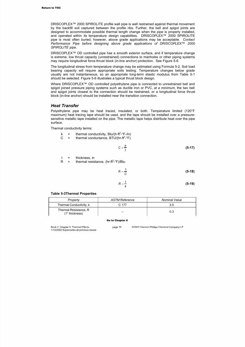
7/23/2019 The Performance Pipe Engineering Manual
http://slidepdf.com/reader/full/the-performance-pipe-engineering-manual 78/208
Book 2: Chapter 5: Thermal Effects page 76 ©2002 Chevron Phillips Chemical Company LP1/12/2002 Supercedes all previous issues
DRISCOPLEX™ 2000 SPIROLITE profile wall pipe is well restrained against thermal movementby the backfill soil captured between the profile ribs. Further, the bell and spigot joints aredesigned to accommodate possible thermal length change when the pipe is properly installed,and operated within its temperature design capabilities. DRISCOPLEX™ 2000 SPIROLITEpipe is most often buried, however, above grade applications may be acceptable. Contact Performance Pipe before designing above grade applications of DRISCOPLEX™ 2000
SPIROLITE pipe.
DRISCOPLEX™ OD controlled pipe has a smooth exterior surface, and if temperature changeis extreme, low thrust capacity (unrestrained) connections to manholes or other piping systemsmay require longitudinal force thrust block (in-line anchor) protection. See Figure 5-6.
The longitudinal stress from temperature change may be estimated using Formula 5-2. Soil loadbearing capacity will require appropriate soils testing. Temperature changes below gradeusually are not instantaneous, so an appropriate long-term elastic modulus from Table 5-1should be selected. Figure 5-6 illustrates a typical thrust block design.
Where DRISCOPLEX™ OD controlled polyethylene pipe is connected to unrestrained bell andspigot joined pressure piping systems such as ductile iron or PVC, at a minimum, the two belland spigot joints closest to the connection should be restrained, or a longitudinal force thrustblock (in-line anchor) should be installed near the transition connection.
Heat Transfer Polyethylene pipe may be heat traced, insulated, or both. Temperature limited (120°Fmaximum) heat tracing tape should be used, and the tape should be installed over a pressure-sensitive metallic tape installed on the pipe. The metallic tape helps distribute heat over the pipesurface.
Thermal conductivity terms:
k = thermal conductivity, Btu/(h-ft2-°F-/in)C = thermal conductance, BTU/(hr-ft2-°F)
t
k C = (5-17)
t = thickness, inR = thermal resistance, (hr-ft2-°F)/Btu
C R
1= (5-18)
k
t R = (5-19)
Table 5-3Thermal Properties
Property ASTM Reference Nominal Value
Thermal Conductivity, k C 177 3.5
Thermal Resistance, R(1” thickness)
– 0.3
Go to Chapter 6
Return to TOC

7/23/2019 The Performance Pipe Engineering Manual
http://slidepdf.com/reader/full/the-performance-pipe-engineering-manual 79/208
Book 2: Chapter 6: Above Grade Supporting page 77 ©2002 Chevron Phillips Chemical Company LP1/12/02002 Supercedes all previous issues
6. Above Grade Supporting Above grade applications frequently require non-continuous support for DRISCOPLEX™ ODcontrolled polyethylene pipe. Such applications usually involve piping in a rack or trestle, onsleepers, or suspended from an overhead structure. In such cases, structures must provide
proper pipeline support, accommodate thermal expansion and contraction movement, andprovide support spacing that limits vertical deflection between supports.
Supports for DRISCOPLEX™ OD controlled pipe must cradle at least the bottom 120° of the
pipe, and be at least 1/2 pipe diameter wide. Edges should be rounded or rolled to preventcutting into the pipe. Commercial pipe supports such as u-bolts, narrow strap-type hangers, androller type supports are unsuitable unless modified for width and cradling. The weight of the pipeand its contents must be distributed over a broad surface. Narrow support surfaces can produce
Figure 6-2 Pipeline Hanger
Figure 6-1 Pipeline Supports
Return to TOC

7/23/2019 The Performance Pipe Engineering Manual
http://slidepdf.com/reader/full/the-performance-pipe-engineering-manual 80/208
Book 2: Chapter 6: Above Grade Supporting page 78 ©2002 Chevron Phillips Chemical Company LP1/12/02002 Supercedes all previous issues
high concentrated stress, and possibly lead to pipeline failure.
Support Spacing
Support spacing depends upon the allowable deflection between supports, which in turndepends upon the pipeline, the fluid within it, and the service temperature. Performance Piperecommends that the allowable long-term deflection between supports should not exceed 1".Recommended support spacing may be determined from Formula 6-1.
( )4
5
384
F P
SS
W W
y I E L
+
= (6-1)
where:
LS = distance between supports, inE = long-term modulus for the service temperature, lb/in2 (Table 5-1)I = moment of inertia, in4 (Formula 5-5)
yS = deflection between supports, inWP = weight of pipe, lb/inWF = weight of fluid in pipe, lb/in
Each support along a piping run is loaded from both sides. When run supports are equallyspaced, the load on supports along the run is:
( )F P RUN W W LW += (6-2)
where:
WRUN = load on supports along the run, lb
The supports at the beginning and the end of the run are loaded from only one side, thus the
load on end supports is:
( )2
F P END
W W LW
+
= (6-3)
where:
WEND = load on end supports, lb
Figure 6-3 Deflection BetweenSu orts
Return to TOC

7/23/2019 The Performance Pipe Engineering Manual
http://slidepdf.com/reader/full/the-performance-pipe-engineering-manual 81/208
Book 2: Chapter 6: Above Grade Supporting page 79 ©2002 Chevron Phillips Chemical Company LP1/12/02002 Supercedes all previous issues
Pipe Rack Support Pipes supported in an overhead rack require design consideration for both support spacing andthermal length change. Support beams are spaced according to vertical deflection limits, andthe rack width accommodates the total thermal expansion offset plus the diameter of the pipe.Pipe supports should be allowed to move along support beams, or otherwise accommodatehorizontal movement as the pipe deflects laterally with changing temperature. See Chapter 5,“Thermal Effects,” for more information.
Center anchored pipes must be allowed to pivot at the anchor point. Side anchored pipes maybe rigidly fixed to the side of the rack.
Several parallel DRISCOPLEX™ OD controlled pipes may be accommodated in racks byspacing supports as required for the smallest diameter pipe, and providing a rack wide enoughfor all of the pipes. Thermal length change is independent of the pipe diameter, so for the sametemperature variation, length change and lateral deflection will be the same for DRISCOPLEX™OD controlled pipes regardless of pipe diameter.
DRISCOPLEX™ OD controlled pipes may be placed in racks parallel to pipes such as steel or fiberglass by using the side anchoring approach. The rack should be widened to accommodatetotal horizontal deflection, and additional support beams added as required. Non-polyethylenepipes should be located on the anchored side to allow the DRISCOPLEX™ OD controlled pipeto deflect horizontally to the opposite side of the rack.
Consult Performance Pipe for all above grade applications for DRISCOPLEX™ 2000SPIROLITE pipe.
Figure 6-5 Pipe Rack - Center Anchored Figure 6-4 Pipe Rack - Side Anchored
Return to TOC
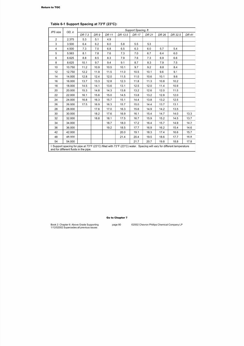
7/23/2019 The Performance Pipe Engineering Manual
http://slidepdf.com/reader/full/the-performance-pipe-engineering-manual 82/208
Book 2: Chapter 6: Above Grade Supporting page 80 ©2002 Chevron Phillips Chemical Company LP1/12/02002 Supercedes all previous issues
Table 6-1 Support Spacing at 73°F (23°C)◊
Support Spacing, ft IPS size OD, in
DR 7.3 DR 9 DR 11 DR 13.5 DR 17 DR 21 DR 26 DR 32.5 DR 41
2 2.375 5.3 5.1 4.9
3 3.500 6.4 6.2 6.0 5.8 5.5 5.3
4 4.500 7.3 7.0 6.8 6.5 6.3 6.0 5.7 5.4
5 5.563 8.1 7.8 7.6 7.3 7.0 6.7 6.4 6.0
6 6.625 8.8 8.5 8.3 7.9 7.6 7.3 6.9 6.6
8 8.625 10.1 9.7 9.4 9.1 8.7 8.3 7.9 7.5
10 10.750 11.2 10.9 10.5 10.1 9.7 9.2 8.8 8.4
12 12.750 12.2 11.9 11.5 11.0 10.5 10.1 9.6 9.1
14 14.000 12.8 12.4 12.0 11.5 11.0 10.6 10.1 9.6
16 16.000 13.7 13.3 12.8 12.3 11.8 11.3 10.8 10.2
18 18.000 14.5 14.1 13.6 13.1 12.5 12.0 11.4 10.9
20 20.000 15.3 14.8 14.3 13.8 13.2 12.6 12.0 11.5
22 22.000 16.1 15.6 15.0 14.5 13.8 13.2 12.8 12.0
24 24.000 16.8 16.3 15.7 15.1 14.4 13.8 13.2 12.5
26 26.000 17.5 16.9 16.3 15.7 15.0 14.4 13.7 13.1
28 28.000 17.6 17.0 16.3 15.6 14.9 14.2 13.5
30 30.000 18.2 17.6 16.9 16.1 15.4 14.7 14.0 13.3
32 32.000 18.8 18.1 17.5 16.7 15.9 15.2 14.5 13.7
34 34.000 18.7 18.0 17.2 16.4 15.7 14.9 14.2
36 36.000 19.2 18.5 17.7 16.9 16.2 15.4 14.6
42 42.000 20.0 19.1 18.3 17.4 16.6 15.7
48 48.000 21.4 20.4 19.5 18.6 17.7 16.8
54 54.000 21.7 20.7 19.8 18.8 17.8
◊ Support spacing for pipe at 73°F (23°C) filled with 73°F (23°C) water. Spacing will vary for different temperatureand for different fluids in the pipe.
Go to Chapter 7
Return to TOC
7/23/2019 The Performance Pipe Engineering Manual
http://slidepdf.com/reader/full/the-performance-pipe-engineering-manual 83/208
Book 2: Chapter 7: Buried Pipe Design page 81 ©2002 Chevron Phillips Chemical Company LP1/12/2002 Supercedes all previous issues
7. Buried Pipe DesignThe design of a subsurface pipe installation is based on principles of soil-structure interaction,that is, the pipe and the surrounding soil act together to control pipe performance. The role eachplays in controlling performance depends on their stiffness relative to each other.
Pipes that are stiffer than the surrounding soil are typically called rigid. With rigid pipes, soil andsurcharge loads are transmitted around the pipe ring from crown (top) to invert (bottom) byvirtue of the pipe’s internal bending and compressive strength. Rigid pipes undergo littledeflection. In some circumstances, polyethylene pipes may behave as a rigid pipe, such as theinstallation of low DR pipe in marsh soils. Here the pipe has greater stiffness than thesurrounding soil, so pipe properties become the major determinant of burial strength.
Pipes that are less stiff than the surrounding soil are called flexible. With weak soil support;relatively small earth loads may cause flexible pipe deflection. However, when properly buried,the surrounding soil greatly increases pipe load-carrying capability as well as reducing earthloads that reach the pipe.
Earth load and surcharge pressures applied to the soil backfill cause vertical and horizontal pipe
deflection. Horizontal deflection, usually extension, results in the pipe wall pushing out into theembedment soil. This action mobilizes passive resistance forces, which in turn limits horizontaldeflection and balances the vertical load. Greater passive resistance is mobilized with stiffer surrounding soil, so less deflection occurs. Most polyethylene pipe should be considered flexiblebecause the pipe’s contribution to resisting deflection is usually less than that of the surroundingsoil.
Therefore, with polyethylene pipe it is important to check each application to ensure theadequacy of the installed design, including both pipe and embedment soils. The designprocedures in this section may be applied to both rigid and flexible pipes.
General Design ProcedureOnce pipe diameter is determined, a pipe is selected by its wall construction. Lower DRDRISCOPLEX™ OD controlled pipe, and higher RSC DRISCOPLEX™ 2000 SPIROLITE pipehave greater external load capacity. However, greater load capacity is also more costly, so theoptimum design is the balance of pipe strength and embedment quality that is capable of handling the imposed loads. The completed buried pipe design should specify the pipe size (ODor ID), wall construction (DR or RSC Class), required embedment materials, and placement(installation) requirements for that embedment.
The initial design step is to determine dead loads and surcharge loads. Following this, the pipeselection is checked for its ability to carry the imposed loads relative to the quality of theembedment that surrounds the pipe.
Usually, this is an iterative process. Several pipe selections may need to be tried before settling
on the optimum design. The pipe selection may need to be changed if loads or embedment arechanged, or where an initially selected pipe is insufficient or excessive for the anticipated loads.
Typically, only the loads around the pipe ring (circumferential direction) are checked. Thedesigner usually assumes that there are no significant loads acting in the longitudinal (axial)direction along the pipe. This assumption is reasonable for buried pipe that is supporteduniformly along its length.
Return to TOC

7/23/2019 The Performance Pipe Engineering Manual
http://slidepdf.com/reader/full/the-performance-pipe-engineering-manual 84/208
Book 2: Chapter 7: Buried Pipe Design page 82 ©2002 Chevron Phillips Chemical Company LP1/12/2002 Supercedes all previous issues
In this chapter, the methods for calculating loads and the pipe’s response are based onanalytical and empirical equations that are appropriate for polyethylene pipe. Generally, theseequations are sufficient for most designs, but they are not exact due to the non-homogeneousnature of soil, the difficulty in characterizing soil as an engineering material, the complexity of soil-pipe interaction, and the variability of construction. Other satisfactory methods for designmay be available.
The design guidelines in this manual are contingent upon the pipe being installed according torecognized principles and standards for flexible pipe installation such as ASTM D-2321Standard Practice for underground Installation of Thermoplastic Pipe for Sewers and Other Gravity-Flow applications, ASTM D-2774 Standard Practice for Underground Installation of Thermoplastic Pressure Pipe, Performance Pipe Bulletin PP 517 SPIROLITE™ InstallationGuide, and PPI Handbook of Polyethylene Pipe Underground Installation of PolyethylenePiping . Because of complexities in soil-pipe interaction, this chapter should not be substitutedfor the judgment of a professional engineer for achieving specific project requirements. Somecases may require more exact solutions than can be obtained from the equations and methodsin this chapter.
Loads on Buried PipeThe load applied to a buried pipe consists of dead load and surcharge load. The dead load isthe permanent load from the weight of soil and pavement above the pipe. Surcharge loads areloads applied at the surface and may or may not be permanent. Surcharge loads include theloads from vehicles and structures. Vehicular loads are called live loads.
Dead Loads
In designing polyethylene pipes, it is commonplace toassume that the overburden load applied to the pipecrown is equal to the weight of the soil column (or prismatic element) projecting above the pipe. Often, this
is referred to as the prism load. See Figure 7-1.
The prism load is a handy convention for calculating theearth pressure on the pipe when estimating verticaldeflection, but the actual load transmitted to a pipe fromthe soil mass depends on the relative soil stiffness andpipe stiffness. The dead load applied to a flexible plasticpipe may be considerably less than the prism loadbecause soil shear resistance transfers part of the soilload that is directly above the pipe into trench sidewallsand embedment. This transfer is called arching. Toaccount for arching, pipe designers often calculate loads
using the Marston method.Design methods for both prism and arching loads follow. The designer may use both methodsfor a buried pipe design.
Prism Load
The simplest case for determining the vertical earth load on a horizontal surface in a mass of soil occurs when the soil has uniform stiffness and weight throughout, with no large voids or
Figure 7-1 Soil Prism
Return to TOC

7/23/2019 The Performance Pipe Engineering Manual
http://slidepdf.com/reader/full/the-performance-pipe-engineering-manual 85/208
Book 2: Chapter 7: Buried Pipe Design page 83 ©2002 Chevron Phillips Chemical Company LP1/12/2002 Supercedes all previous issues
buried structures present. Under these conditions, the vertical earth pressure acting on ahorizontal surface at a depth is equal to the prism load per unit area.
H w P E = (7-1)
Where:
PE = vertical soil pressure, lb/ft2 w = unit weight of soil, lb/ft3 H = soil height above pipe crown, ft
Soil Arching
Theoretically, the prism load occurs on a buried pipe only when the pipe has stiffness equivalentto that of the surrounding soil. More commonly, the pipe and soil are not the same stiffness, sothe pipe either sees more or less than the prism load, depending on the relative pipe stiffnessand soil stiffness.
When the pipe is less stiff than the soil, as is the case with most flexible pipe, the soil above thepipe distributes load away from the pipe and into the soil beside the pipe.
Arching may be defined as the difference between the applied load and the prism load. Theterm arching is usually taken to imply a reduction in vertical load. When the pipe takes on morevertical load than the prism load, reverse arching is said to occur.
Downward backfill movement mobilizes arching inthe backfill above a buried pipe. This may beinitiated by pipe deflection, compression of thedeeper layers of the backfill, or settlement beneaththe pipe.
For a flexible pipe, arching is usually initiated byvertical deflection of the pipe crown. The soil tries
to follow the pipe downward, but soil movement isrestrained by shear resistance (frictional forces andcohesion) along shear planes in the backfill. Thisaction causes part of the weight of the backfill soilto be transferred into the adjacent soil. Therefore,the amount of force exerted on the pipe by thebackfill is less than the weight of the backfill soilmass, that is, less than the prism load.
In most cases, arching is permanent and it occurs in most stable applications. However, archingis maintained by soil shear stresses and may not occur when pipe is located beneath largevibrating machines, in shallow cover locations subjected to vehicular traffic, or in soft, unstablesoil backfills.
Marston Load
When calculating the earth load on a flexible pipe, the Marston load generally gives a morerealistic value than the prism load. Based on experiments and field measurements, Marstonpublished a buried pipe design method in 1930 that accounts for arching. His method is widelyaccepted and can be found in ASCE Manual No. 60.
Figure 7-2 Soil Arching Development
Return to TOC

7/23/2019 The Performance Pipe Engineering Manual
http://slidepdf.com/reader/full/the-performance-pipe-engineering-manual 86/208
Book 2: Chapter 7: Buried Pipe Design page 84 ©2002 Chevron Phillips Chemical Company LP1/12/2002 Supercedes all previous issues
Marston considered pipe buried in a trench and pipe buried in an embankment to be differentcases. The backfill soil in a trench is considered to be supported through shear stresses by theundisturbed trench wall soil. This is the most common case for polyethylene pipe arching.Marston’s formula gives the equation for finding the loads on a flexible pipe buried in a trench.This equation can be modified to obtain the vertical soil pressure applied to a pipe installed in atrench as given in Formula 7-2.
DDM Bw C P = (7-2)
Where terms are previously defined1 and:
PM = vertical soil pressure, lb/ft2 BD = trench width at pipe crown, ftCD = load coefficient
'2
1'2
Ku
eC
DB
H Ku
D
−
−= (7-3)
e = natural log base number, 2.71828K = Rankine earth pressure coefficient
Φ−=
245tan2K (7-4)
Φ = internal soil friction angle, degu’ = friction coefficient between backfill and trench sides
Ku´ values may be characterized as follows:
Table 7-1 Typical Values for Ku'
Soil Typical Value for Ku’
Saturated clay 0.110
Ordinary clay 0.130
Saturated top soil 0.150
Sand and gravel 0.165
Clean granular soil 0.192
The load applied to a pipe in an embankment is typically higher than that for a pipe in a trench.The actual load depends on the relative stiffness between the embankment soil and the pipe.For an embankment condition, the prism load is typically used for calculating vertical pressureon flexible pipe.
Soil Creep
When analytical methods are not available for precise calculations, pipe designers frequentlyignore soil creep, especially when the backfill is cohesionless. This is a conservative design
1All terms for Chapter 7 formulas are defined in Chapter 7. Where previously defined terms are referenced, it refers
to previously defined terms in Chapter 7. Terms from other chapters in the Manual do not apply.
Return to TOC
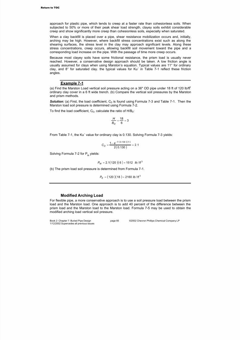
7/23/2019 The Performance Pipe Engineering Manual
http://slidepdf.com/reader/full/the-performance-pipe-engineering-manual 87/208
Book 2: Chapter 7: Buried Pipe Design page 85 ©2002 Chevron Phillips Chemical Company LP1/12/2002 Supercedes all previous issues
approach for plastic pipe, which tends to creep at a faster rate than cohesionless soils. Whensubjected to 50% or more of their peak shear load strength, clayey soils exhibit considerablecreep and show significantly more creep than cohesionless soils, especially when saturated.
When a clay backfill is placed over a pipe, shear resistance mobilization occurs and, initially,arching may be high. However, where backfill stress concentrations exist such as along the
shearing surfaces, the stress level in the clay may approach significant levels. Along thesestress concentrations, creep occurs, allowing backfill soil movement toward the pipe and acorresponding load increase on the pipe. With the passage of time more creep occurs.
Because most clayey soils have some frictional resistance, the prism load is usually never reached. However, a conservative design approach should be taken. A low friction angle isusually assumed for clays when using Marston’s equation. Typical values are 11° for ordinaryclay, and 8° for saturated clay. the typical values for Ku´ in Table 7-1 reflect these frictionangles.
Example 7-1
(a) Find the Marston Load vertical soil pressure acting on a 36" OD pipe under 18 ft of 120 lb/ft3
ordinary clay cover in a 6 ft wide trench. (b) Compare the vertical soil pressures by the Marstonand prism methods.
Solution: (a) First, the load coefficient, CD is found using Formula 7-3 and Table 7-1. Then theMarston load soil pressure is determined using Formula 7-2.
To find the load coefficient, CD, calculate the ratio of H/BD:
36
18==
DB
H
From Table 7-1, the Ku´ value for ordinary clay is 0.130. Solving Formula 7-3 yields:
( )( )
( )1.2
130.02
1 3130.02
=−
=−e
C D
Solving Formula 7-2 for PM
yields:
( )( ) 3/151261201.2 ft lbP M ==
(b) The prism load soil pressure is determined from Formula 7-1.
( )( ) 3/216018120 ft lbP E ==
Modified Arching Load
For flexible pipe, a more conservative approach is to use a soil pressure load between the prismload and the Marston load. One approach is to add 40 percent of the difference between theprism load and the Marston load to the Marston load. Formula 7-5 may be used to obtain themodified arching load vertical soil pressure.
Return to TOC

7/23/2019 The Performance Pipe Engineering Manual
http://slidepdf.com/reader/full/the-performance-pipe-engineering-manual 88/208

7/23/2019 The Performance Pipe Engineering Manual
http://slidepdf.com/reader/full/the-performance-pipe-engineering-manual 89/208
Book 2: Chapter 7: Buried Pipe Design page 87 ©2002 Chevron Phillips Chemical Company LP1/12/2002 Supercedes all previous issues
Surcharge Load The design methods that follow may be used to determine vertical pressures on the pipe fromsurface loads. The formulas are accurate only to the extent that they are appropriate for a givenapplication. Therefore, it is recommended that a professional engineer review the final design.
Surcharge loads may be distributed loads, such as a footing, a foundation or an ash pile, or may
be point loads, such as vehicle wheels. The load is distributed through the soil such that there isa reduction in pressure with increasing depth or horizontal distance from the surcharge loadarea. The pressure at a point beneath the surcharge load depends on the magnitude of the loadand on the surface area over which the surcharge is applied. Usual design practice is to equatethe surcharge load on a buried pipe with downward pressure acting on a plane at the pipecrown. Once the surcharge load is determined, the total load acting on the pipe is the sum of theearth load and the surcharge load.
Distributed Load Over Pipe
This design method may be used to find a rectangular area, distributed surcharge load on aburied pipe beneath structures such as footings, floors or other stationary loads such as coal or
ash piles.The method assumes the Boussinesq equation for pressure, and finds the soil pressure actingat a point below the surcharge, and located at the same depth as the crown of the pipe. Thispressure is considered to be equal to the vertical pressure acting on the pipe.
Figure 7-4 Distributed Surcharge Load Over Pipe
In Figure 7-4A, the point pressure is found by dividing the rectangular surcharge area (ABCD)into four sub-area rectangles (a, b, c, and d), which have a common corner, E, in the surchargearea, and over the pipe. The surcharge load is the sum of the four sub-area loads at thesubsurface point. Each sub-area load, is calculated by multiplying the surcharge pressure by aninfluence coefficient, IC, from Table 7-2.
d c baL P P P P P +++= (7-8)
Where
Return to TOC
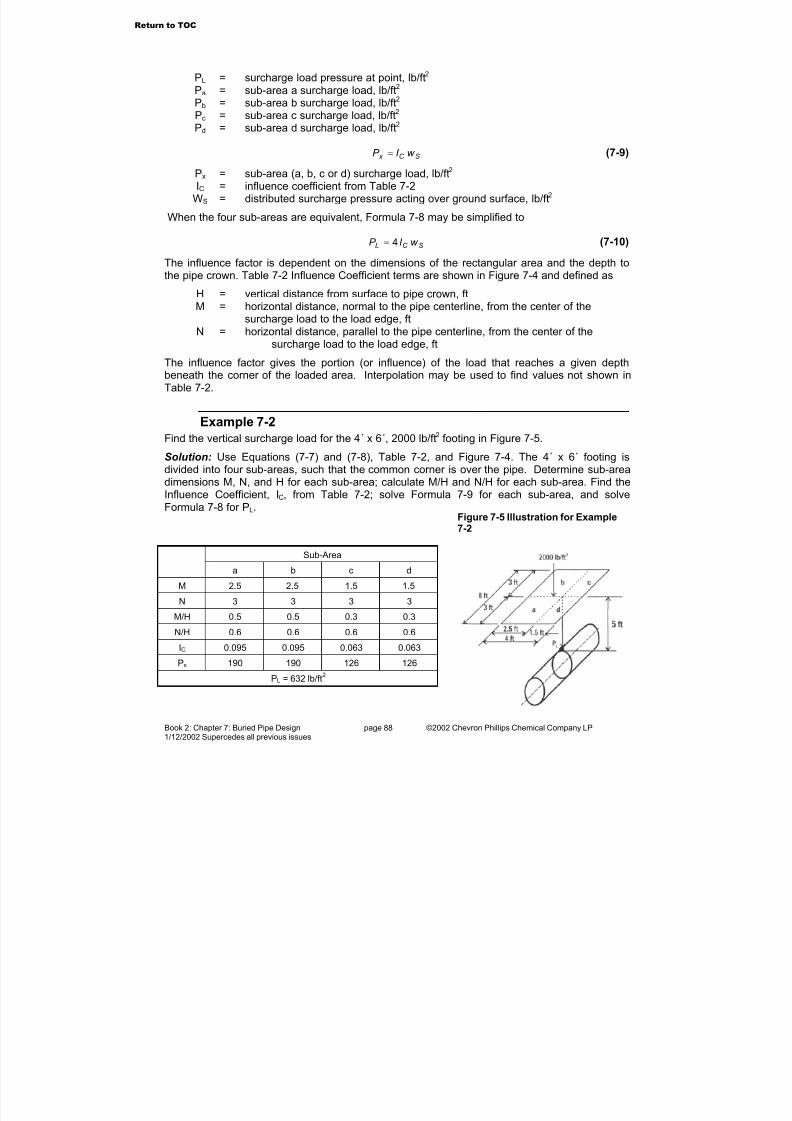
7/23/2019 The Performance Pipe Engineering Manual
http://slidepdf.com/reader/full/the-performance-pipe-engineering-manual 90/208
Book 2: Chapter 7: Buried Pipe Design page 88 ©2002 Chevron Phillips Chemical Company LP1/12/2002 Supercedes all previous issues
PL = surcharge load pressure at point, lb/ft2 Pa = sub-area a surcharge load, lb/ft2 Pb = sub-area b surcharge load, lb/ft2 Pc = sub-area c surcharge load, lb/ft2 Pd = sub-area d surcharge load, lb/ft2
SC x w I P = (7-9)
Px = sub-area (a, b, c or d) surcharge load, lb/ft2 IC = influence coefficient from Table 7-2
WS = distributed surcharge pressure acting over ground surface, lb/ft2
When the four sub-areas are equivalent, Formula 7-8 may be simplified to
SC L w I P 4= (7-10)
The influence factor is dependent on the dimensions of the rectangular area and the depth tothe pipe crown. Table 7-2 Influence Coefficient terms are shown in Figure 7-4 and defined as
H = vertical distance from surface to pipe crown, ft
M = horizontal distance, normal to the pipe centerline, from the center of thesurcharge load to the load edge, ft
N = horizontal distance, parallel to the pipe centerline, from the center of thesurcharge load to the load edge, ft
The influence factor gives the portion (or influence) of the load that reaches a given depthbeneath the corner of the loaded area. Interpolation may be used to find values not shown inTable 7-2.
Example 7-2
Find the vertical surcharge load for the 4´ x 6´, 2000 lb/ft2 footing in Figure 7-5.
Solution: Use Equations (7-7) and (7-8), Table 7-2, and Figure 7-4. The 4´ x 6´ footing isdivided into four sub-areas, such that the common corner is over the pipe. Determine sub-areadimensions M, N, and H for each sub-area; calculate M/H and N/H for each sub-area. Find theInfluence Coefficient, IC, from Table 7-2; solve Formula 7-9 for each sub-area, and solveFormula 7-8 for PL.
Figure 7-5 Illustration for Example7-2
Sub-Area
a b c d
M 2.5 2.5 1.5 1.5
N 3 3 3 3
M/H 0.5 0.5 0.3 0.3
N/H 0.6 0.6 0.6 0.6
IC 0.095 0.095 0.063 0.063
Px 190 190 126 126
PL = 632 lb/ft2
Return to TOC
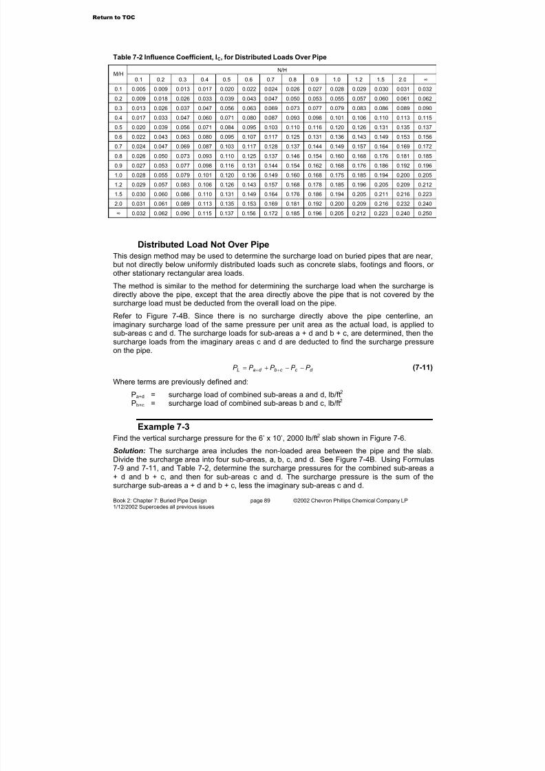
7/23/2019 The Performance Pipe Engineering Manual
http://slidepdf.com/reader/full/the-performance-pipe-engineering-manual 91/208
Book 2: Chapter 7: Buried Pipe Design page 89 ©2002 Chevron Phillips Chemical Company LP1/12/2002 Supercedes all previous issues
Table 7-2 Influence Coefficient, IC, for Distributed Loads Over Pipe
N/HM/H
0.1 0.2 0.3 0.4 0.5 0.6 0.7 0.8 0.9 1.0 1.2 1.5 2.0 ∞
0.1 0.005 0.009 0.013 0.017 0.020 0.022 0.024 0.026 0.027 0.028 0.029 0.030 0.031 0.032
0.2 0.009 0.018 0.026 0.033 0.039 0.043 0.047 0.050 0.053 0.055 0.057 0.060 0.061 0.062
0.3 0.013 0.026 0.037 0.047 0.056 0.063 0.069 0.073 0.077 0.079 0.083 0.086 0.089 0.090
0.4 0.017 0.033 0.047 0.060 0.071 0.080 0.087 0.093 0.098 0.101 0.106 0.110 0.113 0.115
0.5 0.020 0.039 0.056 0.071 0.084 0.095 0.103 0.110 0.116 0.120 0.126 0.131 0.135 0.137
0.6 0.022 0.043 0.063 0.080 0.095 0.107 0.117 0.125 0.131 0.136 0.143 0.149 0.153 0.156
0.7 0.024 0.047 0.069 0.087 0.103 0.117 0.128 0.137 0.144 0.149 0.157 0.164 0.169 0.172
0.8 0.026 0.050 0.073 0.093 0.110 0.125 0.137 0.146 0.154 0.160 0.168 0.176 0.181 0.185
0.9 0.027 0.053 0.077 0.098 0.116 0.131 0.144 0.154 0.162 0.168 0.176 0.186 0.192 0.196
1.0 0.028 0.055 0.079 0.101 0.120 0.136 0.149 0.160 0.168 0.175 0.185 0.194 0.200 0.205
1.2 0.029 0.057 0.083 0.106 0.126 0.143 0.157 0.168 0.178 0.185 0.196 0.205 0.209 0.212
1.5 0.030 0.060 0.086 0.110 0.131 0.149 0.164 0.176 0.186 0.194 0.205 0.211 0.216 0.223
2.0 0.031 0.061 0.089 0.113 0.135 0.153 0.169 0.181 0.192 0.200 0.209 0.216 0.232 0.240
∞ 0.032 0.062 0.090 0.115 0.137 0.156 0.172 0.185 0.196 0.205 0.212 0.223 0.240 0.250
Distributed Load Not Over Pipe
This design method may be used to determine the surcharge load on buried pipes that are near,but not directly below uniformly distributed loads such as concrete slabs, footings and floors, or other stationary rectangular area loads.
The method is similar to the method for determining the surcharge load when the surcharge isdirectly above the pipe, except that the area directly above the pipe that is not covered by thesurcharge load must be deducted from the overall load on the pipe.
Refer to Figure 7-4B. Since there is no surcharge directly above the pipe centerline, animaginary surcharge load of the same pressure per unit area as the actual load, is applied tosub-areas c and d. The surcharge loads for sub-areas a + d and b + c, are determined, then thesurcharge loads from the imaginary areas c and d are deducted to find the surcharge pressureon the pipe.
d c c bd aL P P P P P −−+= ++ (7-11)
Where terms are previously defined and:
Pa+d = surcharge load of combined sub-areas a and d, lb/ft2 Pb+c = surcharge load of combined sub-areas b and c, lb/ft2
Example 7-3
Find the vertical surcharge pressure for the 6’ x 10’, 2000 lb/ft2 slab shown in Figure 7-6.
Solution: The surcharge area includes the non-loaded area between the pipe and the slab.Divide the surcharge area into four sub-areas, a, b, c, and d. See Figure 7-4B. Using Formulas7-9 and 7-11, and Table 7-2, determine the surcharge pressures for the combined sub-areas a+ d and b + c, and then for sub-areas c and d. The surcharge pressure is the sum of thesurcharge sub-areas a + d and b + c, less the imaginary sub-areas c and d.
Return to TOC
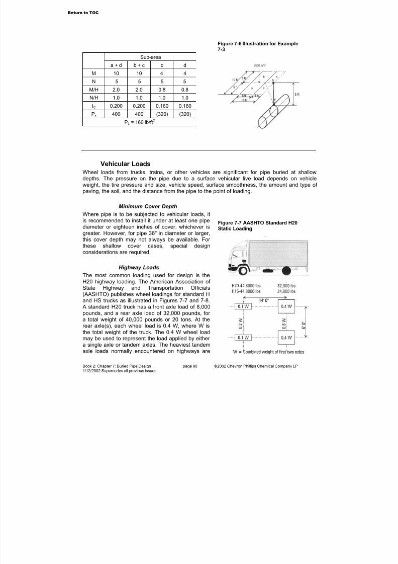
7/23/2019 The Performance Pipe Engineering Manual
http://slidepdf.com/reader/full/the-performance-pipe-engineering-manual 92/208
Book 2: Chapter 7: Buried Pipe Design page 90 ©2002 Chevron Phillips Chemical Company LP1/12/2002 Supercedes all previous issues
Sub-area
a + d b + c c d
M 10 10 4 4
N 5 5 5 5
M/H 2.0 2.0 0.8 0.8
N/H 1.0 1.0 1.0 1.0
IC 0.200 0.200 0.160 0.160
Px 400 400 (320) (320)
PL = 160 lb/ft2
Vehicular Loads
Wheel loads from trucks, trains, or other vehicles are significant for pipe buried at shallowdepths. The pressure on the pipe due to a surface vehicular live load depends on vehicleweight, the tire pressure and size, vehicle speed, surface smoothness, the amount and type of paving, the soil, and the distance from the pipe to the point of loading.
Minimum Cover Depth
Where pipe is to be subjected to vehicular loads, itis recommended to install it under at least one pipe
diameter or eighteen inches of cover, whichever isgreater. However, for pipe 36" in diameter or larger,this cover depth may not always be available. For these shallow cover cases, special designconsiderations are required.
Highway Loads
The most common loading used for design is theH20 highway loading. The American Association of State Highway and Transportation Officials(AASHTO) publishes wheel loadings for standard Hand HS trucks as illustrated in Figures 7-7 and 7-8.
A standard H20 truck has a front axle load of 8,000pounds, and a rear axle load of 32,000 pounds, for a total weight of 40,000 pounds or 20 tons. At therear axle(s), each wheel load is 0.4 W, where W isthe total weight of the truck. The 0.4 W wheel loadmay be used to represent the load applied by either a single axle or tandem axles. The heaviest tandemaxle loads normally encountered on highways are
Figure 7-7 AASHTO Standard H20
Static Loading
Figure 7-6 Illustration for Example7-3
Return to TOC
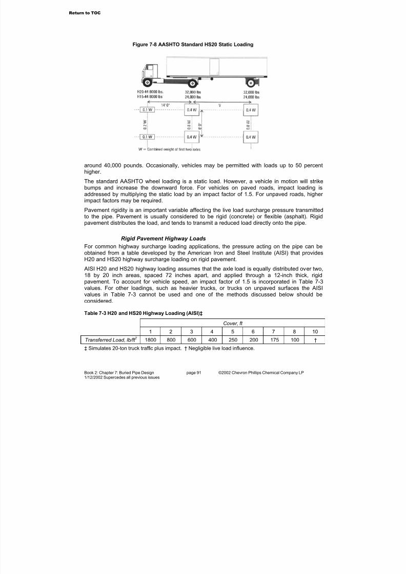
7/23/2019 The Performance Pipe Engineering Manual
http://slidepdf.com/reader/full/the-performance-pipe-engineering-manual 93/208
Book 2: Chapter 7: Buried Pipe Design page 91 ©2002 Chevron Phillips Chemical Company LP1/12/2002 Supercedes all previous issues
around 40,000 pounds. Occasionally, vehicles may be permitted with loads up to 50 percenthigher.
The standard AASHTO wheel loading is a static load. However, a vehicle in motion will strikebumps and increase the downward force. For vehicles on paved roads, impact loading isaddressed by multiplying the static load by an impact factor of 1.5. For unpaved roads, higher impact factors may be required.
Pavement rigidity is an important variable affecting the live load surcharge pressure transmittedto the pipe. Pavement is usually considered to be rigid (concrete) or flexible (asphalt). Rigidpavement distributes the load, and tends to transmit a reduced load directly onto the pipe.
Rigid Pavement Highway Loads
For common highway surcharge loading applications, the pressure acting on the pipe can beobtained from a table developed by the American Iron and Steel Institute (AISI) that providesH20 and HS20 highway surcharge loading on rigid pavement.
AISI H20 and HS20 highway loading assumes that the axle load is equally distributed over two,18 by 20 inch areas, spaced 72 inches apart, and applied through a 12-inch thick, rigidpavement. To account for vehicle speed, an impact factor of 1.5 is incorporated in Table 7-3values. For other loadings, such as heavier trucks, or trucks on unpaved surfaces the AISIvalues in Table 7-3 cannot be used and one of the methods discussed below should beconsidered.
Table 7-3 H20 and HS20 Highway Loading (AISI)‡
Cover, ft
1 2 3 4 5 6 7 8 10
Transferred Load, lb/ft 2 1800 800 600 400 250 200 175 100 †
‡ Simulates 20-ton truck traffic plus impact. † Negligible live load influence.
Figure 7-8 AASHTO Standard HS20 Static Loading
Return to TOC

7/23/2019 The Performance Pipe Engineering Manual
http://slidepdf.com/reader/full/the-performance-pipe-engineering-manual 94/208
Book 2: Chapter 7: Buried Pipe Design page 92 ©2002 Chevron Phillips Chemical Company LP1/12/2002 Supercedes all previous issues
Off-Highway and Unpaved Road Loads
Off-highway vehicles may be considerably heavier than H20 or HS20 trucks, and these vehiclesfrequently operate on unpaved roads that may have uneven surfaces. Thus impact factorshigher than 1.5 may be reached depending on the vehicle speed. Except for slow traffic, animpact factor of 2.0 to 3.0 should be considered.
During construction, both permanent and temporary underground pipelines may be subjected toheavy vehicle loading from construction equipment. A designated vehicle crossing with specialdesign measures such as temporary pavement or structural sheeting may be prudent, as wellas vehicle speed controls to limit impact loading.
Vehicular Loads As Point Loads
There are generally two approaches for calculating vehicle live load surcharge pressure. Themore conservative approach is to treat the wheel load as a concentrated (point) load. The other is to treat it as a distributed load spread over the contact area of the tire with the ground (imprintarea). The pressure due to a distributed load and the pressure due to a concentrated load beginto approach the same value at a depth of about twice the square root of the loaded area.
The distributed load method gives more realistic values where the depth equals less than twicethe square root of the loaded area, whereas for deeper depths concentrated loads are preferredbecause the calculations are simpler and typically more conservative.
The pressure distribution under a concentrated load varies with depth as illustrated in Figure 7-9. When the live load is calculated using the pointload methods in the following sections, aconservative approach is to assume that themaximum pressure at the pipe crown is distributedacross the entire pipe.
A key consideration in determining live load pressureon the pipe is the location of vehicle wheels relative
to the pipe. A higher pressure may occur below apoint between two vehicles passing in adjacent lanesthan directly under a single vehicle wheel. Thisdepends on the depth of cover.
When depths are greater than four or five feet, thecombined H20 load for two separate wheelsstraddling the pipe is greater than that for a singlewheel directly over the pipe. Deeper than five feet, H20 loads are not usually significantbecause the load is attenuated significantly compared loads under one or two feet of cover.However, greater live loads may produce design significant effects at depths greater than fivefeet. Therefore, the designer should check load conditions for a single wheel directly over thepipe, and for two wheels spaced six feet apart and centered over the pipe.
Single Wheel Load Centered On Pipe
To check a single wheel load centered directly over the pipe, a method based on Holl’sintegration of Boussinesq’s equation assumes that the wheel load is a concentrated (point) load.Holl’s integration finds the pressure at the depth of the pipe crown that is distributed over asurface three feet long and the width of the pipe outside diameter.
Figure 7-9 Concentrated Vehicular Load Pressure Distribution at Various
Return to TOC

7/23/2019 The Performance Pipe Engineering Manual
http://slidepdf.com/reader/full/the-performance-pipe-engineering-manual 95/208
Book 2: Chapter 7: Buried Pipe Design page 93 ©2002 Chevron Phillips Chemical Company LP1/12/2002 Supercedes all previous issues
Holl’s Integration
Holl’s equation for the average vertical pressure acting on a pipe due to a concentrated surfaceload is:
Holl’s Equation
DLW I C P LI
H L = (7-12)
Where terms are previously defined and:
II = impact factor CH = load coefficient, Table 7-4WL = wheel load, lbL = pipe length, ftD = pipe outside diameter, ft
If the pipe is longer than 3 ft, the usual practice is to assume a length of 3 ft. Values for CH arefound in Table 7-4 as a function of D/2H and L/2H where H is the depth of cover.
Example 7-4
Find the single H20 rear wheel live load surcharge pressure on a 30" OD pipe buried 4 feetdeep. Assume an impact factor of 1.5.
Solution: Use Formula 7-12, Table 7-4, and Figure 7-7. To solve Formula 7-12, the loadcoefficient, CH, from Table 7-4 is required. For 4 ft of cover, D/2H = 0.31, and L/2H = 0.38.Interpolating Table 7-4 for CH yields 0.189. From Figure 7-7, the H20 rear wheel live load is 0.4x 40,000 = 16,000 lb. Solving Formula 7-12 yields:
( )( )( )
=
12
30
3
000,165.1189.0LP
2/598 ft lbP L =
Multiple Wheel Loads Along Pipe Length
In many cases, the maximum load on the pipe occurs when a single (or dual) wheel is locateddirectly over the pipe. However, at some depths the combined load due to more than one wheelmay be larger than the single wheel load. This usually occurs at a location along the pipe that isnot directly beneath a wheel load. This point (Figure 7-10, Case I, Point 2) will usually be
centered between two wheel loads.
Point Load on Pipe Crown
The Boussinesq point load equation may be used to find the wheel load pressure on the pipe,neglecting any pavement effects. Pavement effects are covered later using a modified form of Boussinesq’s equation, Formula 7-13.
Return to TOC

7/23/2019 The Performance Pipe Engineering Manual
http://slidepdf.com/reader/full/the-performance-pipe-engineering-manual 96/208
Book 2: Chapter 7: Buried Pipe Design page 94 ©2002 Chevron Phillips Chemical Company LP1/12/2002 Supercedes all previous issues
Table 7-4 Load Coefficient, CH, for Holl's Integration of Boussinesq's Equation
L/2H D/2H
0.1 0.2 0.3 0.4 0.5 0.6 0.7 0.8 0.9 1.0 1.2 1.5 2.0 20.0
0.1 0.019 0.037 0.053 0.067 0.079 0.089 0.097 0.103 0.108 0.112 0.117 0.121 0.124 0.127
0.2 0.037 0.072 0.103 0.131 0.155 0.174 0.189 0.202 0.211 0.219 0.229 0.238 0.244 0.248
0.3 0.053 0.103 0.149 0.190 0.224 0.252 0.274 0.292 0.306 0.318 0.333 0.346 0.355 0.361
0.4 0.067 0.131 0.190 0.241 0.284 0.320 0.349 0.373 0.391 0.405 0.425 0.442 0.454 0.462
0.5 0.079 0.155 0.224 0.284 0.336 0.379 0.414 0.441 0.463 0.481 0.505 0.525 0.540 0.550
0.6 0.089 0.174 0.252 0.320 0.379 0.428 0.467 0.499 0.524 0.544 0.572 0.596 0.613 0.625
0.7 0.097 0.189 0.274 0.349 0.414 0.467 0.511 0.546 0.574 0.597 0.628 0.655 0.674 0.688
0.8 0.103 0.202 0.292 0.373 0.441 0.499 0.546 0.584 0.615 0.639 0.674 0.703 0.725 0.740
0.9 0.108 0.211 0.306 0.391 0.463 0.524 0.574 0.615 0.647 0.673 0.711 0.743 0.766 0.783
1.0 0.112 0.219 0.318 0.405 0.481 0.544 0.597 0.639 0.673 0.701 0.740 0.775 0.800 0.818
1.2 0.117 0.229 0.333 0.425 0.505 0.572 0.628 0.674 0.711 0.740 0.783 0.821 0.849 0.871
1.5 0.121 0.238 0.346 0.422 0.525 0.596 0.655 0.703 0.743 0.775 0.821 0.863 0.895 0.920
2.0 0.124 0.244 0.355 0.454 0.540 0.613 0.674 0.725 0.766 0.800 0.849 0.895 0.930 0.960
20.0 0.127 0.248 0.361 0.462 0.550 0.625 0.688 0.740 0.783 0.818 0.871 0.920 0.960 1.000
Boussinesq’s Equation
5
3
2
3
r
H W I P LI
Lπ
= (7-13)
Where terms are previously defined and:H = vertical depth to point on pipe crown, ftr = distance from the point of load application to the pipe crown, ft
22 H X r += (7-14)
Where:
X = horizontal distance from the point of load application to the pipe crown, ft
Return to TOC

7/23/2019 The Performance Pipe Engineering Manual
http://slidepdf.com/reader/full/the-performance-pipe-engineering-manual 97/208
Book 2: Chapter 7: Buried Pipe Design page 95 ©2002 Chevron Phillips Chemical Company LP1/12/2002 Supercedes all previous issues
Using the Boussinesq point load equation in this wayis conservative, as the pressure applied to the pointon the pipe crown is taken as the pressure appliedacross the pipes diameter.
Equation (7-12) applies only where the axle is
located directly over the pipe, and when seeking thepipe crown load at some point between the wheels.This is depicted in Figure 7-10, Case I.
Example 7-5
Determine the vertical soil pressure exerted on a 12"pipe buried 2 ft deep when two 16,000 lb wheel loadscross simultaneously over the pipe. Assume theloads are 6 feet apart. (Six feet is the typical wheelspacing on an axle, and the normal separation for wheel loads traveling in adjacent lanes.)
Solution: Use Formulas 7-13 and 7-14. Assumingthe vehicle is traveling, a 1.5 impact factor is applied.The maximum load will be at the center between thetwo wheels, thus X = 3 ft. Determine r from Formula7-14.
ft r 61.332 22 =+=
Then,
( )( )( )( )2
5
2
/5.14961.32
2000,165.13 ft lbP L ==π
This is the load from each wheel; however, the load on the pipe crown is from both wheels, thus
2/2992 ft lbP L =
Point Load Not On Pipe Crown
With some modification of equation terms, the pressure at a point other than at the pipe crownmay be determined. A pipe buried along a road shoulder is such an application. Pictorially, this
is Figure 7-10, Case II. For this application, H and r are determined using the following formulas:
+
= −
2'
tan 1
DH
X α (7-15)
Figure 7-10 Concentrated Point Load
Return to TOC

7/23/2019 The Performance Pipe Engineering Manual
http://slidepdf.com/reader/full/the-performance-pipe-engineering-manual 98/208
Book 2: Chapter 7: Buried Pipe Design page 96 ©2002 Chevron Phillips Chemical Company LP1/12/2002 Supercedes all previous issues
( )α cos12
' −+=D
H H (7-16)
22'
22 DD
H X r −
++= (7-17)
Where terms are previously defined and
H’ = depth of cover, ft
Multiple Wheel Loads on Rigid Pavement
The Portland Cement Association method may be used to find the load on a pipe from multiplewheel loads on rigid pavement. The solution accounts for pavement rigidity, and the stiffness of the pipe embedment soil. To determine the maximum load when two vehicles pass each other,two common cases are checked. The first calculates the load directly under a wheel, and theother calculates the combined load of two passing vehicles. Usually the later case gives thehighest load.
The pressure at a point beneath a single wheel is given by:
2S
LI H L
R
W I C P = (7-18)
Where terms are previously defined and
RS = radius of stiffness, ft
( )
12
'1124
2
3
E
hE
R Sν −
= (7-19)
Where
E = pavement modulus, lb/in2 (4,000,000 lb/in2 for concrete)h = pavement thickness, inν = Poisson’s ratio (0.15 for concrete)E’ = embedment soil modulus, lb/in2 (Table 7-7)
Example 7-6
Find the pressure at the crown of the pipe illustrated in Figure 7-11, using an impact factor of 1.5. Pavement is 12" thick and the pipe is 4 feet below the pavement surface. Assume E´ = 700
lb/in
2
.Solution: Using Formula 7-19, solve for RS; then determine CH from Table 7-5. Using Formula7-18, solve for each wheel load. The total pressure on the pipe is the sum of the four wheelloads.
ft R S 52.212
)700)(15.01(12
)12)(000,000,4(4
2
3
=−
=
Return to TOC
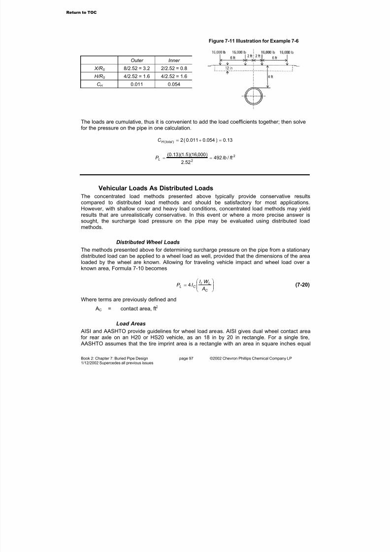
7/23/2019 The Performance Pipe Engineering Manual
http://slidepdf.com/reader/full/the-performance-pipe-engineering-manual 99/208
Book 2: Chapter 7: Buried Pipe Design page 97 ©2002 Chevron Phillips Chemical Company LP1/12/2002 Supercedes all previous issues
Outer Inner
X/R S 8/2.52 = 3.2 2/2.52 = 0.8
H/R S 4/2.52 = 1.6 4/2.52 = 1.6
C H 0.011 0.054
Figure 7-11 Illustration for Example 7-6
The loads are cumulative, thus it is convenient to add the load coefficients together; then solvefor the pressure on the pipe in one calculation.
13.0)054.0011.0(2)( =+=total H C
2
2/492
52.2
)000,16)(5.1)(13.0(ft lbP L ==
Vehicular Loads As Distributed Loads
The concentrated load methods presented above typically provide conservative resultscompared to distributed load methods and should be satisfactory for most applications.However, with shallow cover and heavy load conditions, concentrated load methods may yieldresults that are unrealistically conservative. In this event or where a more precise answer issought, the surcharge load pressure on the pipe may be evaluated using distributed loadmethods.
Distributed Wheel Loads
The methods presented above for determining surcharge pressure on the pipe from a stationarydistributed load can be applied to a wheel load as well, provided that the dimensions of the arealoaded by the wheel are known. Allowing for traveling vehicle impact and wheel load over aknown area, Formula 7-10 becomes
=
C
LI C L
A
W I I P 4 (7-20)
Where terms are previously defined and
AC = contact area, ft2
Load Areas
AISI and AASHTO provide guidelines for wheel load areas. AISI gives dual wheel contact areafor rear axle on an H20 or HS20 vehicle, as an 18 in by 20 in rectangle. For a single tire, AASHTO assumes that the tire imprint area is a rectangle with an area in square inches equal
Return to TOC

7/23/2019 The Performance Pipe Engineering Manual
http://slidepdf.com/reader/full/the-performance-pipe-engineering-manual 100/208
Book 2: Chapter 7: Buried Pipe Design page 98 ©2002 Chevron Phillips Chemical Company LP1/12/2002 Supercedes all previous issues
to 0.01WL where WL is the wheel load in lbs. The AASHTO area has a 1 to 2.5 ratio of direction-of-traffic length to tire width. The contact area may also be found by dividing the wheel load bythe tire pressure. For off road and heavy trucks, the tire contact area should be obtained fromthe vehicle manufacturer.
Example 7-7(a) Using the distributed load method, find the pressure at the crown of a 24" O.D. polyethylenepipe with 2 ft of cover under an HS20 vehicle with a 16,000 lb wheel load and an impact factor of 1.5. Assume the AISI contact area for a dual tire rear wheel.
(b) Compare this value with that obtained using the Boussinesq point load equation.
Figure 7-12 Illustration for Example 7-7
Solution: (a) The vertical pressure at the crown of the pipe may be found using Formula 7-20,and Table 7-2. The live load is divided into four equal areas, with the common corner centeredover the pipe as shown in Figure 7-12.
375.02
12/9==
H
M
420.02
12/10==
H
N
By interpolation of Table 7-2, the influence coefficient, IC, is 0.059, thus
2
/2265
12
20
12
18
)000,16)(5.1(
)059.0(4 ft lbP L =
=
(b) To determine the point load, Equations (7-12) and (7-13) apply. Since the load is directlyabove the pipe, r = H = 2 ft, and
2
5
3
/2865)2(2
)2)(000,16)(5.1(3ft lbP L ==
π
Return to TOC
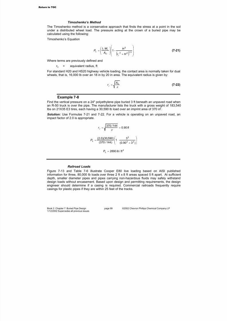
7/23/2019 The Performance Pipe Engineering Manual
http://slidepdf.com/reader/full/the-performance-pipe-engineering-manual 101/208
Book 2: Chapter 7: Buried Pipe Design page 99 ©2002 Chevron Phillips Chemical Company LP1/12/2002 Supercedes all previous issues
Timoshenko’s Method
The Timoshenko method is a conservative approach that finds the stress at a point in the soilunder a distributed wheel load. The pressure acting at the crown of a buried pipe may becalculated using the following:
Timoshenko’s Equation
( )
+
−
=
5.122
3
1
H r
H
A
W I P
C
LI L
γ
(7-21)
Where terms are previously defined and
r γ = equivalent radius, ft
For standard H20 and HS20 highway vehicle loading, the contact area is normally taken for dualwheels, that is, 16,000 lb over an 18 in by 20 in area. The equivalent radius is given by:
π γ
C Ar = (7-22)
Example 7-8
Find the vertical pressure on a 24" polyethylene pipe buried 3 ft beneath an unpaved road whenan R-50 truck is over the pipe. The manufacturer lists the truck with a gross weight of 183,540lbs on 21X35 E3 tires, each having a 30,590 lb load over an imprint area of 370 in2.
Solution: Use Formulas 7-21 and 7-22. For a vehicle is operating on an unpaved road, animpact factor of 2.0 is appropriate.
ft r 90.0144/370
==π
γ
+−=
)390.0(
31
)144/370(
)590,30)(0.2(22
2
LP
2/2890 ft lbP L =
Railroad Loads
Figure 7-13 and Table 7-6 illustrate Cooper E80 live loading based on AISI published
information for three, 80,000 lb loads over three 2 ft x 8 ft areas spaced 5 ft apart. At sufficientdepth, smaller diameter pipes and pipes carrying non-hazardous fluids may safely withstanddesign loads without encasement. Based upon design and permitting requirements, the designengineer should determine if a casing is required. Commercial railroads frequently requirecasings for plastic pipes if they are within 25 feet of the tracks.
Return to TOC
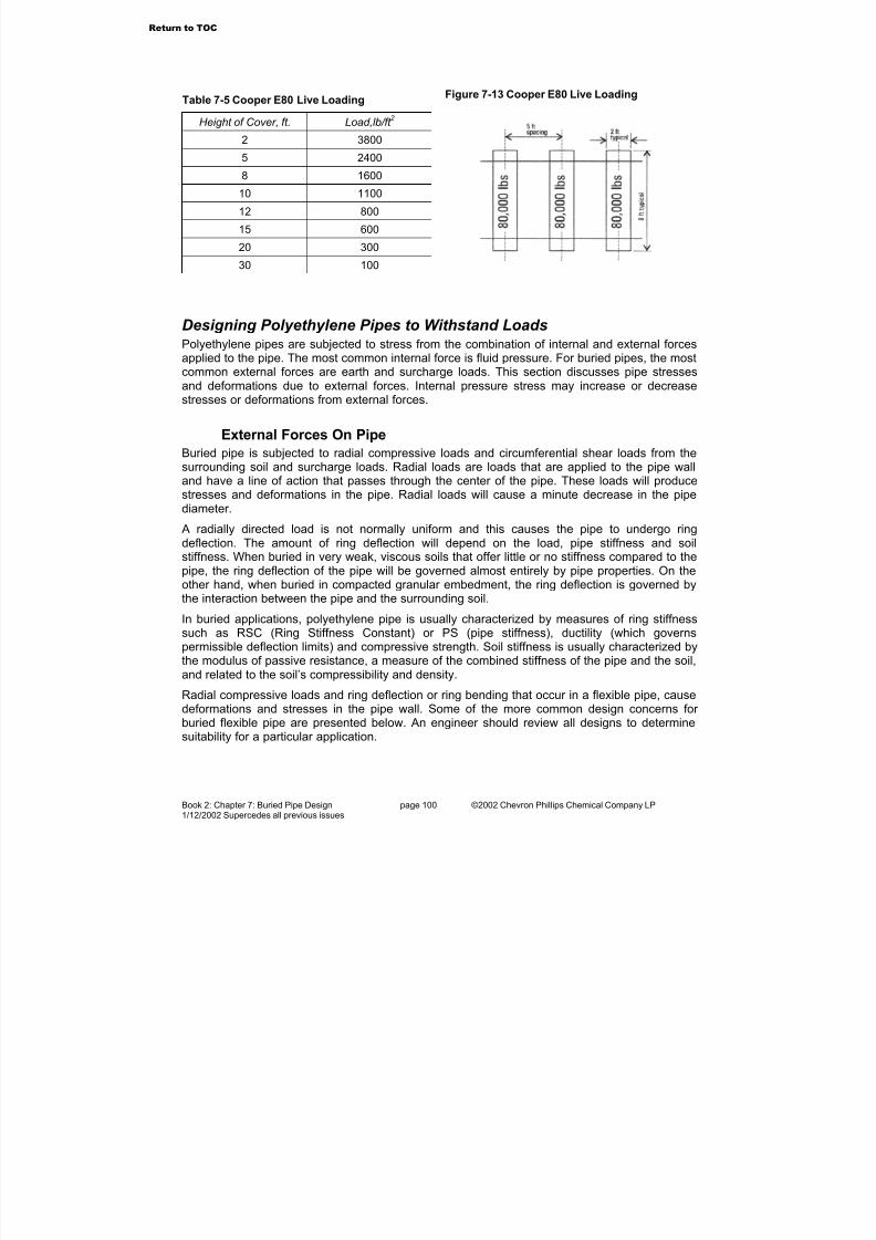
7/23/2019 The Performance Pipe Engineering Manual
http://slidepdf.com/reader/full/the-performance-pipe-engineering-manual 102/208
Book 2: Chapter 7: Buried Pipe Design page 100 ©2002 Chevron Phillips Chemical Company LP1/12/2002 Supercedes all previous issues
Table 7-5 Cooper E80 Live Loading
Height of Cover, ft. Load,lb/ft 2
2 3800
5 2400
8 1600
10 1100
12 800
15 600
20 300
30 100
Figure 7-13 Cooper E80 Live Loading
Designing Polyethylene Pipes to Withstand LoadsPolyethylene pipes are subjected to stress from the combination of internal and external forcesapplied to the pipe. The most common internal force is fluid pressure. For buried pipes, the mostcommon external forces are earth and surcharge loads. This section discusses pipe stressesand deformations due to external forces. Internal pressure stress may increase or decreasestresses or deformations from external forces.
External Forces On Pipe
Buried pipe is subjected to radial compressive loads and circumferential shear loads from thesurrounding soil and surcharge loads. Radial loads are loads that are applied to the pipe walland have a line of action that passes through the center of the pipe. These loads will producestresses and deformations in the pipe. Radial loads will cause a minute decrease in the pipediameter.
A radially directed load is not normally uniform and this causes the pipe to undergo ringdeflection. The amount of ring deflection will depend on the load, pipe stiffness and soilstiffness. When buried in very weak, viscous soils that offer little or no stiffness compared to thepipe, the ring deflection of the pipe will be governed almost entirely by pipe properties. On theother hand, when buried in compacted granular embedment, the ring deflection is governed bythe interaction between the pipe and the surrounding soil.
In buried applications, polyethylene pipe is usually characterized by measures of ring stiffnesssuch as RSC (Ring Stiffness Constant) or PS (pipe stiffness), ductility (which governspermissible deflection limits) and compressive strength. Soil stiffness is usually characterized bythe modulus of passive resistance, a measure of the combined stiffness of the pipe and the soil,
and related to the soil’s compressibility and density.
Radial compressive loads and ring deflection or ring bending that occur in a flexible pipe, causedeformations and stresses in the pipe wall. Some of the more common design concerns for buried flexible pipe are presented below. An engineer should review all designs to determinesuitability for a particular application.
Return to TOC

7/23/2019 The Performance Pipe Engineering Manual
http://slidepdf.com/reader/full/the-performance-pipe-engineering-manual 103/208
Book 2: Chapter 7: Buried Pipe Design page 101 ©2002 Chevron Phillips Chemical Company LP1/12/2002 Supercedes all previous issues
Constrained Pipe Wall Compressive Stress
When a non-pressurized pipe that is confined in a dense embedment is subjected to a radiallydirected soil pressure, a circumferential, compressive thrust occurs in its wall. This is similar tothe thrust force that occurs within the wall of a ring when it is squeezed. This thrust creates aring (or hoop) compressive stress within the pipe wall. This is similar to a hoop tensile stressfrom internal pressure, but compressive stress acts in the opposite direction.
As is often the case, the radial soil pressure that causes compressive stress is not uniform.However, for convenience in calculating wall compressive stress, radial soil pressure isassumed to be uniform and equal to the vertical soil pressure at the crown of the pipe.
With buried pressure pipe, internal pressure may be greater than the radial external pressureapplied by the soil. This results in a tensile stress rather than a compressive stress in the pipewall. Thus for pressure pipe, compressive wall stresses are normally not considered. This canbe verified by comparing internal pressure hoop stress to wall compressive stress.
When subjected to a uniform radial soil pressure, the compressive stress in the pipe wall is:
DRISCOPLEX™ OD controlled pipe:
t DP S OT
288= (7-23)
DRISCOPLEX™ 2000 SPIROLITE pipe:
A
DP S OT
288= (7-24)
Where
PT = vertical load applied to pipe, lb/ft2 S = pipe wall compressive stress, lb/in2 DO = pipe outside diameter, int = pipe wall thickness, in
A = pipe wall profile average cross-sectional area, in2/in
Because arching commonly occurs for entrenched pipe, the modified arching load rather thanthe prism load is used to determine the vertical soil pressure at the pipe crown.
The pipe wall compressive stress should be compared to an allowable material stress value thatshould be determined by testing. The recommended, long-term compressive strength designvalue for DRISCOPLEX™ polyethylene pipe is 800 lb/in2.
Example 7-9
Find the pipe wall compressive ring (or hoop) stress in a DRISCOPLEX™ 2000 SPIROLITE 36"Class 100 pipe buried under 18 ft of cover. The ground water level is at the surface, the
saturated weight of the insitu silty-clay soil is 120 lbs/ft3 and the trench width equals the pipediameter plus 3 ft.
Solution: Determine the modified arching load using Formula 7-5. The arching coefficient fromFormula 7-7 or from Figure 7-3 is
83.0=F
Return to TOC

7/23/2019 The Performance Pipe Engineering Manual
http://slidepdf.com/reader/full/the-performance-pipe-engineering-manual 104/208
Book 2: Chapter 7: Buried Pipe Design page 102 ©2002 Chevron Phillips Chemical Company LP1/12/2002 Supercedes all previous issues
Although net soil pressure is equal to the buoyant weight of the soil, ground water pressure isalso acting on the pipe. Therefore the total pressure (water and earth load) can be found usingthe saturated unit weight of the soil.
2/1793)18)(120)(83.0( inlbP C ==
Next, solve Formula 7-24 for the compressive stress. For DRISCOPLEX™ 2000 SPIROLITE36" Class 100 pipe, the wall cross-sectional area, A, and outside diameter, DO are found inDRISCOPLEX™ 2000 SPIROLITE product literature. A is 0.470 in2/in, and DO is 36 plus twicethe 2.02" wall height, or 40.04 in.
2/530)470.0)(288(
)04.40)(1793(inlbS ==
The application is within the 800 lb/in2 allowable stress guideline.
Unconstrained Pipe Wall Buckling
Flexible pipe may be viewed as having the cross section of a long, slender column rolled into acylinder. Compressive thrust, in combination with radially directed forces, may cause instabilityor buckling, that is, a large wrinkle or dimple in the pipe wall. This type of deflection can becompared to the Euler buckling of a column.
Unconstrained pipe wall buckling can be a consideration for low pressure and non-pressurepipes where the pipe is not externally supported by embedment, or when embedment provideslittle or no support. Compared to the capacity for tensile wall stress from internal pressure,unconstrained flexible pipe has less resistance to external, radially directed pressure. Someexamples of external pressures on unconstrained pipe include: external atmospheric pressurefrom vacuum within the pipe; external hydrostatic load such as groundwater above a slipliner, or water above partially full underwater pipeline; a column separation in a liquid flow in a downhillpipeline; siphoning or a reduced internal pressure where a flow liquid in a pipeline crests a rise;
and cavitation due to pump shut-off or start-up. If an unconstrained pipe will be subjected to anexternal pressure during service, the unconstrained buckling resistance should be checked.
For unconstrained pipe, the critical external pressure or negative pressure above which bucklingcan occur may be estimated by:
For DRISCOPLEX™ 2000 SPIROLITE pipe:
32 )1(
24
M
P CR
D
I E P
µ −= (7-25)
Where
PCR = vertical load applied to pipe, lb/ft2
E = elastic modulus, lb/in2 (Table 5-1)IP = profile wall moment of inertia, in4/inµ = Poisson’s ratio
DM = pipe mean diameter, in
Return to TOC

7/23/2019 The Performance Pipe Engineering Manual
http://slidepdf.com/reader/full/the-performance-pipe-engineering-manual 105/208
Book 2: Chapter 7: Buried Pipe Design page 103 ©2002 Chevron Phillips Chemical Company LP1/12/2002 Supercedes all previous issues
For DRISCOPLEX™ 2000 SPIROLITE pipe:
Z DD I M 2+= (7-26)
For DRISCOPLEX™ OD controlled pipe:
t DD OM 06.1−= (7-27)
Where
DI = pipe inside diameter, inZ = profile wall centroid, in
DO = pipe outside diameter t = pipe minimum wall thickness
Poisson’s ratio, µ, for polyethylene pipe is 0.45 for long-term loading and 0.35 for short-termloading. Expressing critical external buckling pressure in terms of DR for OD controlled pipe,Formula 7-25 becomes
2
2 1
1
)1(
2
−−=
DR
E P CR
µ
(7-28)
Where
DR = pipe dimension ratio
t
DDR O= (7-29)
Ovality Effects
Ovality or deflection of the pipe diameter reduces buckling resistance because the bendingmoment in the pipe wall increases.
CR O P f P = (7-30)
Where
P = buckling pressure, lb/in2 f O = ovality compensation factor, Figure 7-14
Initially deflected unconstrained pipe generally assumes an oval shape. The percent deflection(ovality) of pipe is determined by
−=
D
DDDeflection O100% (7-31)
Where
D = pipe average diameter, inDO = pipe minimum diameter, in
See Table 5-1 for elastic modulus values for determining critical buckling pressure in Formulas7-25 and 7-28. The modulus selected should account for the temperature of the pipe and theduration of the applied load. When unconstrained pipes are installed on or above the surface,sunlight heating can increase pipe temperature and reduce buckling resistance.
Return to TOC

7/23/2019 The Performance Pipe Engineering Manual
http://slidepdf.com/reader/full/the-performance-pipe-engineering-manual 106/208
Book 2: Chapter 7: Buried Pipe Design page 104 ©2002 Chevron Phillips Chemical Company LP1/12/2002 Supercedes all previous issues
The designer should compare the critical buckling pressure to the actual anticipated pressure,and apply a safety factor commensurate with his assessment of the application. Safety factorsin the range of 2 to 1 are common, but specific circumstances may warrant a higher or lower safety factor. An alternative to a direct safety factor may be to apply a long-term elastic modulusto a short-term stress event.
The resilience and toughness of DRISCOPLEX™ OD controlled and DRISCOPLEX™ 2000SPIROLITE pipe may allow the pipe to recover from a short-term or one-time buckling or flattening event. For example, a high DR, unconstrained OD controlled pipe may be pressed flatby a short duration vacuum inside the pipe, but relieving the vacuum can allow the pipe torecover most of its original round shape. When such events are rare or one-time, a loss of
serviceability or permanent damage is not anticipated. However, repetitive unconstrainedbuckling events can cause permanent damage. If temporary buckling events are possible withDRISCOPLEX™ 2000 SPIROLITE pipe, bell and spigot joints should be extrusion-welded toenhance joint sealing capability.
Example 7-10
Find the allowable ground water level above a 24" Class 160 DRISCOPLEX™ 2000 SPIROLITEpipe installed in a casing without grout in the annular space. Consider cases where the pipe isbelow the normal water table, and where the water table rises during a flood.
Solution: Use Formulas 7-26, 7-28 and 7-30; Bulletin PP-401 ASTM F 894 High Density Polyethylene Pipe Product Data; Figure 7-14 and Table 5-1 for elastic modulus values. Thecritical external collapse pressure depends upon the how long the water level is above the pipe.If the water level is constant, a long-term elastic modulus should be used, but if the water levelrises only occasionally, an elastic modulus for lesser duration may be applied.
Bulletin PP-401 supplies pipe dimensions and I values. For 24" Class 160 pipe, I is 0.124 in4/inand Z, the wall centroid, is 0.50 in. Solving Formula 7-26
inDM 0.25)50.0(224 =+=
Figure 7-14 Ovality CompensationFactor for Unconstrained Buckling
Return to TOC

7/23/2019 The Performance Pipe Engineering Manual
http://slidepdf.com/reader/full/the-performance-pipe-engineering-manual 107/208
Book 2: Chapter 7: Buried Pipe Design page 105 ©2002 Chevron Phillips Chemical Company LP1/12/2002 Supercedes all previous issues
For a constant water table above the pipe, Table 5-1 indicates a 50-year, 73° F modulus of 28,200 lb/in2, thus Formula 7-28 yields
2
32/79.6
)25)(45.01(
)124.0)(200,28)(24(inlbP CR =
−=
Assuming 5% ovality and a 2 to 1 safety factor, f O
from Figure 7-14 is 0.64. Formula 7-30 yields
OH ft inlbP 22 0.5/17.2
2
)79.6)(64.0(===
Flooding conditions are occasional happenings, usually lasting a few days to a week or so.From Table 5-1, 1000 hours (41.6 days) is about twice the expected flood duration, so a valueof 43,700 lb/in2 provides about a 2 to 1 safety margin. Solving as above,
2
32/44.10
)25)(45.01(
)124.0)(700,43)(24(inlbP CR =
−=
OH ft inlbP 22 4.15/68.6)44.10)(64.0( ===
Constrained Pipe Wall Buckling
Buckling resistance is increased when flexible pipe is embedded in soil. The soil and pipecouple together to resist buckling forces. A vertically applied thrust force causes the pipe towiden horizontally, but horizontal pipe deflection is restrained by the embedment soil, thus thepipes critical buckling pressure increases. A pipe/soil interaction occurs when the depth of cover is sufficient to mobilize soil support. A publication by the American Water Works Association, AWWA C-950, indicates that at least four feet of cover is needed to mobilize soil support.
AWWA C-950 provides a design equation for buckling of a buried plastic pipe. The followingconstrained pipe buckling equation is applicable to DRISCOPLEX™ OD controlled and
DRISCOPLEX™ 2000 SPIROLITE pipe.
For OD Controlled Pipe
3)1(12''
65.5
−=
DR
I E E BR
N P WC (7-32)
For DRISCOPLEX™ 2000 SPIROLITE Pipe
3''
65.5
M
WC D
I E E BR
N P = (7-33)
Where terms are previously defined and
PWC = allowable constrained buckling pressure, lb/in2 N = safety factor R = buoyancy reduction factor
H
H R
'33.01−= (7-34)
H’ = groundwater height above pipe, ftH = cover above pipe, ft
Return to TOC
7/23/2019 The Performance Pipe Engineering Manual
http://slidepdf.com/reader/full/the-performance-pipe-engineering-manual 108/208
Book 2: Chapter 7: Buried Pipe Design page 106 ©2002 Chevron Phillips Chemical Company LP1/12/2002 Supercedes all previous issues
B’ = elastic support factor
)065.0(41
1'
H eB
−+= (7-35)
E’ = soil reaction modulus, lb/in2 (Table 7-7)
The designer should apply a safety factor appropriate to the application. A safety factor of 2.0has been used for thermoplastic pipe.
The allowable constrained buckling pressure should be compared to the total vertical stressacting on the pipe crown from the combined load of soil and groundwater or floodwater. It isprudent to check buckling resistance against a groundwater level for a 100-year-flood. In thiscalculation the total vertical stress is typically taken as the prism load pressure for saturated soil,plus the fluid pressure of any floodwater above the ground surface.
Example 7-11
Find the allowable buckling pressure for a DRISCOPLEX™ 2000 SPIROLITE 36" Class 100 36"pipe, installed in compacted soil embedment having an E´ of 2000 lb/in2. Determine if Class 100pipe is sufficient for an applied load from 18 feet of cover and ground water to the surface.
Solution: Solve Formula 7-33 using Formulas 7-26, 7-35, 7-34 and Table 5-1. DRISCOPLEX™2000 SPIROLITE pipe dimensions and properties are published in Bulletin PP-401. For DRISCOPLEX™ 2000 SPIROLITE 36" Class 100 pipe, I is 0.171 in4/in, and Z is 0.58 in. Solvefor terms DM, B’, and R.
inDM 16.37)58.0(236 =+=
446.041
1'
))18(065.0(=
+=
−eB
67.018
1833.01 =−=R
Under a 100-year-flood condition, soil cover, H, and floodwater height, H´, are both 18 feet.
From Table 5-1, E is 28,200 lb/in2 for 50 years at 73° F. A common practice is a safety factor of 2. Solving Formula 7-32,
3)16.37(
)171.0)(800,28)(2000)(446.0)(67.0(
2
65.5=WC P
22 /3051/17.21 ft lbinlbP WC ==
The load applied to the pipe is found using the prism load, Formula 7-1.
(In this example, the specified soil reaction modulus, E´, is an empirical value that wasdeveloped using prism load rather than arching load methods. Therefore, the prism soil loadmust be used. If a soil reaction modulus value is developed using arching or modified archingmethods, then soil loads should be calculated using the appropriate method. See discussionson Soil Reaction Modulus and Vertical Soil Pressure.)
2/2160)18)(120( ft lbP E ==
Return to TOC

7/23/2019 The Performance Pipe Engineering Manual
http://slidepdf.com/reader/full/the-performance-pipe-engineering-manual 109/208
Book 2: Chapter 7: Buried Pipe Design page 107 ©2002 Chevron Phillips Chemical Company LP1/12/2002 Supercedes all previous issues
The allowable buckling stress, PWC, is greater than the applied load pressure, PE, therefore,Class 100 pipe is satisfactory for this installation.
Ring Deflection
Some vertical pipe deflection is desirable to promote arching and to mobilize the passive soilresistance forces that support the pipe. However, deflection may affect other pipe or systemperformance areas, such as pipe material long-term strain capability, pipeline hydraulic capacityand compatibility with cleaning equipment. In DRISCOPLEX™ 2000 SPIROLITE pipe, bell-and-spigot joint sealing capability may be affected by excessive deflection.
The two components of buried pipe deflection are construction deflection and service loaddeflection. Construction deflection occurs during shipping and handling and placing embedmentaround the pipe up to the pipe crown. Construction deflection incorporates all forces acting onthe pipe up to the point where backfill is placed above the pipe. Service load deflection occursfrom backfill placement above the pipe and from applied surcharge loads. The deflectionobserved in a buried pipe after the completing an installation is the sum of construction
deflection and service load deflection.
Several methods are available for determining flexible pipe deflection from earth loads andsurcharge loads. Historically, Spangler’s Modified Iowa formula has been used to find thedeflection of plastic pipes. Other methods include closed form solutions, and numerical methodssuch as finite element solutions. Alternatives to Spangler’s formula may give more accuratevalues, but they usually require more precise information on soil and pipe properties. Therefore,these methods are not as commonly used as Spangler’s Modified Iowa formula.
Spangler’s Modified Iowa Formula can be written for DRISCOPLEX™ 2000 SPIROLITE pipeas:
+=∆
'061.0)(24.1144
E D
RSC LK P
D X
I
T
I
(7-36)
And for DRISCOPLEX™ OD controlled pipe as:
+
−
=∆
'061.01
1
3
2144 3
E DR
E
LK P
D
X T
I
(7-37)
Where
∆X = horizontal deflection, inDI = inside diameter, inPT = pipe crown vertical pressure, lb/ft2 K = bedding factor, typically 0.1L = deflection lag factor E’ = soil reaction modulus, lb/in2 E = elastic modulus, lb/in2 (Table 5-1)
Return to TOC

7/23/2019 The Performance Pipe Engineering Manual
http://slidepdf.com/reader/full/the-performance-pipe-engineering-manual 110/208
Book 2: Chapter 7: Buried Pipe Design page 108 ©2002 Chevron Phillips Chemical Company LP1/12/2002 Supercedes all previous issues
)100()100(%M I D
X
D
X Deflection
∆=
∆= (7-38)
DM = mean diameter, in (Formula 7-26 or 7-27)
Soil Reaction Modulus, E´The soil reaction modulus, E’, is an interactive modulus representing the support or stiffness of the embedment soil in reaction to lateral pipe deflection under load. It is dependent on both soiland pipe properties, so there are no convenient laboratory tests to determine the soil reactionmodulus for a given soil.
For the most part the modulus must be determined empirically, that is, it must be found bymeasuring the deflection of a buried pipe, then substituting that value into Spangler’s formulaand back-calculating.
Table 7-7 presents soil reaction modulus values from an extensive field study for the Bureau of Reclamation performed by A. Howard. These values for soil reaction modulus are commonlyused in flexible pipe design.
Howard noted deflection variability along the length of a typical pipeline. To determine maximumdeflection, variability should be accommodated by reducing the Table 7-7 E´ value by 25%, or by adding the deflection percentage given in Table 7-7.
As cover depth increases, so does the earth pressure on the embedment material. Bothhorizontal and vertical pressures exist in a soil mass, but unlike water, these pressures are notnormally equal to each other. As the enveloping or confining pressure is increased on a granular material, soil grains are held together more tightly, and the entire system stiffens. J. Hartley andJ. Duncan published a study of soil reaction modulus variation with depth. Their recommendedsoil reaction modulus values are presented in Table 7-8, and should be considered when cover depth is less than 20 feet.
The vertical soil pressure exerted on a buried flexible pipe is typically equal to the Marston load.
However, Howard’s Bureau of Reclamation E´ values assumed that the pipe was subjected to aprism load, which means that soil arching is incorporated in Howard’s E´ values. When usingTable 7-7 or Table 7-8, the prism load should be used.
The soil reaction modulus represents the stiffness of the soil surrounding the pipe. In Tables 7-7and 7-8, E´ values are given for the embedment material. However, when the insitu trench soilis highly compressible (marsh clay, peat, saturated organic soils, etc.) compared to theembedment around the pipe, the embedment soil may not develop the E´ values presented inthe tables, resulting in pipe deflection greater than the design prediction. Increasing trenchwidth, thereby increasing the width of embedment soil around the pipe, can minimize the effectof highly plastic insitu trench soil.
Janson recommends the use of the short-term pipe elastic modulus value in Spangler’s
equation. The concept is that soil settlement around the buried pipe occurs in discrete events assoil grains shift or fracture. Once movement occurs, soil arching redistributes the load, and nofurther deflection occurs for that event. Since these load increments are felt like impulse loads,the pipe resists them with its short-term elastic modulus.
Return to TOC

7/23/2019 The Performance Pipe Engineering Manual
http://slidepdf.com/reader/full/the-performance-pipe-engineering-manual 111/208
Book 2: Chapter 7: Buried Pipe Design page 109 ©2002 Chevron Phillips Chemical Company LP1/12/2002 Supercedes all previous issues
Table 7-7 Bureau of Reclamation Average E’ Values for Iowa Formula (Initial Deflection)
E’ for Degree of Bedding Compaction, lb/in2
Soil type – pipe bedding material (Unified Classification)† Dumped
Slight (<85% Proctor <40% relative
density)
Moderate(48%-95%
Proctor 40%-70%
relativedensity)
High(>95% Proctor >70% relative
density)
Fine-grained soils (LL>50)‡ Soils with medium to high plasticity
CH, MH, CH-MH
No data available; consult a competent soils engineer; otherwise, useE’ = 0.
Fine-grained soils (LL<50)Soils with medium to no plasticity
CL, ML, CL-ML, with <25% coarse grained particles
50 200 400 1000
Fine-grained soils (LL<50)Soils with medium to no plasticity
CL, ML, CL-ML, with >25% coarse grained particles
Coarse-grained soils with fines
GM, GC, SM, SC ◊ contains >12% fines
100 400 1000 2000
Coarse-grained soils with little or no finesGW, GP, SW, SP ◊
contains <12% fines200 1000 2000 3000
Crushed rock 1000 3000 3000 3000
Accuracy in terms of percentagedeflection▼
±2% ±2% ±1% ±0.5%
† ASTM D 2487; USBR Designation E-3. ‡ LL = Liquid limit. ◊ Or any borderline soil beginning with one of these
symbols, i.e., GM-GC, GC-SC. ▼For ±1% accuracy and predicted deflection of 3%, actual deflection would bebetween 2% and 4%.
Note – Values applicable only for fills less than 50 ft (15 m). No safety factor included in table values. For use inpredicting initial deflections only; appropriate Deflection Lag Factor must be applied for long-term deflections. If
bedding falls on the borderline between two compaction categories, select the lower E’ value or average the twovalues. Percentage Proctor based on laboratory maximum dry density from test standards using 12,500 ft-lb/ft
3
(598,000 J/m2) (ASTM D 698, AASHTO T-99, USBR Designation E-11). 1 lb/in
2= 6.895 kPa.
Table 7-8 Duncan-Hartley Soil Reaction Modulus
E’ for Standard AASHTO Relative Compaction, lb.in2
Type of SoilDepth of Cover, ft 85% 90% 95% 100%
0-5 500 700 1000 1500
5-10 600 1000 1400 2000
10-15 700 1200 1600 2300
Fine-grained soilswith <25% sand
content(CL, ML, CL-ML)
15-20 800 1300 1800 2600
0-5 600 1000 1200 19005-10 900 1400 1800 2700
10-15 1000 1500 2100 3200
Coarse-grained soilswith fines(SM, SC)
15-20 1100 1600 1400 3700
0-5 700 1000 1600 2500
5-10 1000 1500 2200 3300
10-15 1050 1600 2400 3600
Coarse-grained soilswith little or no fines(SP, SW, GP, GW)
15-20 1100 1700 2500 3800
Return to TOC

7/23/2019 The Performance Pipe Engineering Manual
http://slidepdf.com/reader/full/the-performance-pipe-engineering-manual 112/208
Book 2: Chapter 7: Buried Pipe Design page 110 ©2002 Chevron Phillips Chemical Company LP1/12/2002 Supercedes all previous issues
Lag Factor and Long Term Deflection
Long-term buried pipe deflection is determined by both pipe and soil properties, because bothpipe and soil are subjected to visco-elastic deformations. For a properly installed pipe, soilproperties generally prevail.
Visco-elastic deformation can continue forever, but total deformation is typically small. For
example, most buildings settle after construction due to soil creep, but rarely does this causedistress. The same is true for most flexible pipe, whether plastic or metal. Visco-elasticdeformation typically accounts for only a small percentage of the total deflection of the pipe, anda large portion of this deflection normally occurs within a few weeks after installation.
Research conducted by R. Lytton at Texas A&M University, has shown that for properlyinstalled plastic pipe, long-term deflection is controlled principally by the embedment soil.
Spangler recommended addressing visco-elastic effects by using a deflection lag factor in theIowa Formula. Recommended values range from 1.0 to 1.5.
Lytton and Brown published time factors based on a visco-elastic solution for long-termdeflection of pipe installed in saturated clay. The ratio of the 50-year deflection to the 30-day (or short term) deflection gave a lag factor of 1.5. Field measurements of HDPE pipe haveconfirmed values in the same range.
Example 7-12
Estimate the vertical deflection of a DRISCOPLEX™ 2000 SPIROLITE 36" Class 100 installedunder 18 feet of cover. The embedment material is well-graded sandy gravel, compacted to atleast 90 percent of Standard Proctor density.
Solution: Use the prism load, Formula 7-1, Table 7-7 and Formulas 7-37 and 7-39. From Table7-7 the E´ value for compacted sandy gravel or GW-SW soil is 2000 lb/in2. For an estimate of maximum long-term deflection, the value is reduced by 25% to 1500 lb/in2. (The Duncan-Hartleyvalue in Table 7-8 for this material with 18 ft of cover is 1700 lb/in2.)
From Formula 7-1, the prism load on the pipe is:
2/2160)18)(120( ft lbP E ==
Solving Formulas 7-37 and 7-39 yields:
0237.0
)1500)(61.0()58.0(236
100)(24.1(
)5.1)(1.0(
144
2160=
++
=∆
I D
X
%37.2)100)(0237.0(% ==Deflection
Deflection Limits
Flexible pipe deflection is a natural, essential, response to soil loading. Deflection mobilizespassive resistance in the surrounding soil, and promotes arching. Small deflections aredesirable, but large deflections should be limited.
Return to TOC
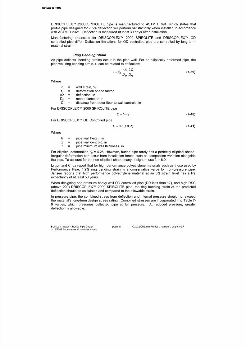
7/23/2019 The Performance Pipe Engineering Manual
http://slidepdf.com/reader/full/the-performance-pipe-engineering-manual 113/208
Book 2: Chapter 7: Buried Pipe Design page 111 ©2002 Chevron Phillips Chemical Company LP1/12/2002 Supercedes all previous issues
DRISCOPLEX™ 2000 SPIROLITE pipe is manufactured to ASTM F 894, which states thatprofile pipe designed for 7.5% deflection will perform satisfactorily when installed in accordancewith ASTM D 2321. Deflection is measured at least 30 days after installation.
Manufacturing processes for DRISCOPLEX™ 2000 SPIROLITE and DRISCOPLEX™ ODcontrolled pipe differ. Deflection limitations for OD controlled pipe are controlled by long-term
material strain.
Ring Bending Strain
As pipe deflects, bending strains occur in the pipe wall. For an elliptically deformed pipe, thepipe wall ring bending strain, ε, can be related to deflection:
M M
DD
C
D
X f
2∆=ε (7-39)
Where
ε = wall strain, %f D = deformation shape factor
∆X = deflection, inDM = mean diameter, inC = distance from outer fiber to wall centroid, in
For DRISCOPLEX™ 2000 SPIROLITE pipe
z hC −= (7-40)
For DRISCOPLEX™ OD Controlled pipe
)06.1(5.0 t C = (7-41)
Where
h = pipe wall height, in
z = pipe wall centroid, int = pipe minimum wall thickness, in
For elliptical deformation, f D = 4.28. However, buried pipe rarely has a perfectly elliptical shape.Irregular deformation can occur from installation forces such as compaction variation alongsidethe pipe. To account for the non-elliptical shape many designers use f D = 6.0.
Lytton and Chua report that for high performance polyethylene materials such as those used byPerformance Pipe, 4.2% ring bending strain is a conservative value for non-pressure pipe.Jansen reports that high performance polyethylene material at an 8% strain level has a lifeexpectancy of at least 50 years.
When designing non-pressure heavy wall OD controlled pipe (DR less than 17), and high RSC(above 200) DRISCOPLEX™ 2000 SPIROLITE pipe, the ring bending strain at the predicteddeflection should be calculated and compared to the allowable strain.
In pressure pipe, the combined stress from deflection and internal pressure should not exceedthe material’s long-term design stress rating. Combined stresses are incorporated into Table 7-9 values, which presumes deflected pipe at full pressure. At reduced pressure, greater deflection is allowable.
Return to TOC

7/23/2019 The Performance Pipe Engineering Manual
http://slidepdf.com/reader/full/the-performance-pipe-engineering-manual 114/208
Book 2: Chapter 7: Buried Pipe Design page 112 ©2002 Chevron Phillips Chemical Company LP1/12/2002 Supercedes all previous issues
Table 7-9 Safe Pressure Pipe Deflection
DR Safe Deflection as
% of Diameter
32.5 8.5
26 7.0
21 6.0
17 5.0
13.5 4.0
11 3.0
9 2.5
Example 7-13
Find the ring bending strain in the wall of the DRISCOPLEX™ 2000 SPIROLITE 36" Class 100
pipe in Example 7-12.Solution: Use Formula 7-40 and f D = 6.0. From Bulletin PP-401, h = 2.02 in., and z = 0.58 in.
%55.00055.0)58.0(236
58.002.2)0237.0(6 ==
+
−=ε
The strain is well below the permissible strain for ASTM F 894 profile pipe.
Design Considerations For Shallow Cover Pipe
Pipe installed under shallow cover does not completely develop a the interaction between pipe
and soil structure interaction; therefore, design methods must be modified. The designer shouldconsider the following three cases: (1) flotation due to insufficient soil cover, (2) ring bendingdue to live load, and (3) upward buckling due to flooding or high groundwater levels.
The exact depth of cover required to fully develop pipe-soil structure interaction depends on theparticular installation conditions.
Shallow Cover Surcharge Load
The preceding design methods assume that the pipe behaves primarily as a membranestructure, that is, the pipe is almost perfectly flexible with little ability to resist bending.
At depths of cover less than one pipe diameter, this membrane action may not develop fully,thus a surcharge load or live load places a bending load on the pipe crown. For this reason,flexible pipe manufacturers often recommend that pipe be buried at least one pipe diameter below a live load. If this cannot be accomplished, the designer should perform a special analysisto determine if the pipe has adequate beam bending strength.
R. Watkins in Minimum Soil Cover Required Over Buried Flexible Cylinders provides a designequation for determining the pipe cross section for shallow cover live load applications. Watkins’method presumes that a combination of pipe flexural strength and the ring resistance of the soilsurrounding the pipe resist the live load at shallow cover. The maximum bending stress
Return to TOC

7/23/2019 The Performance Pipe Engineering Manual
http://slidepdf.com/reader/full/the-performance-pipe-engineering-manual 115/208
Book 2: Chapter 7: Buried Pipe Design page 113 ©2002 Chevron Phillips Chemical Company LP1/12/2002 Supercedes all previous issues
occurring in the pipe wall can be found by considering the top half of the pipe as a pinned-endarch.
For polyethylene pipe, Watkins’ analysis should be used only where the minimum depth of cover is the greater of one-half of the pipe diameter or 18 inches. For lesser cover depths, areinforced concrete cap should be considered.
Based on Watkins’ analysis, the live load pressure on the pipe, PL, should not exceed theFormula 7-43 upper limit
−+≤
A
H Dw S
C DN
I
DN
H K w P O
OO
L288
)(2.7387)(122
2
(7-43)
Where
w = unit weight of soil, lb/ft2 K = passive earth pressure coefficient
Φ−
Φ+=
sin1
sin1K (7-44)
Φ = angle of internal soil friction, degH = cover height, ftN = safety factor DO = pipe outside diameter, inI = pipe wall moment of inertia, in4/inC = distance from outer fiber to wall centroid, inS = material yield strength, lb/in2 A = pipe wall area, in2/in
In developing Formula 7-43, Watkins applied a load to a part of the pipe crown. Therefore, anysurcharge load should be calculated a point load method, rather than a distributed load method.
A design safety factor of at least 2 should be applied.
In addition to the pipe bending check with Watkins’ formula, the designer should check pipe wallcompressive stress, and pipe wall buckling from live load stress. When a pipe is installed withshallow cover below an unpaved surface, rutting can occur, which will not only reduce cover depth, but also increase the impact factor. State highway authorities commonly set a minimumcover depth under below pavement. This cover depth varies by State, but is usually 2.5 to 5 ft.
Shallow Cover Buckling
The buckling resistance of a buried pipe increases with increasing cover depth because thesurrounding soil is stiffened by the increase in overburden pressure. However, a differentbuckling mechanism may occur when pipe is located near the surface.
Groundwater or flooding may apply an external pressure to the pipe that may result in upward
buckling, that is the sides of the pipe deflect inward (negative horizontal deflection) and thecrown deflects upward. This mechanism is possible when cover depth is insufficient to restrainupward crown movement and when the pipe is empty or partially full.
Shallow cover may not be sufficient for complete development of soil support. AWWA C-950suggests that a minimum cover of four feet is required, however, larger diameter pipe mayrequire as much as a diameter and a half to develop full support.
Return to TOC
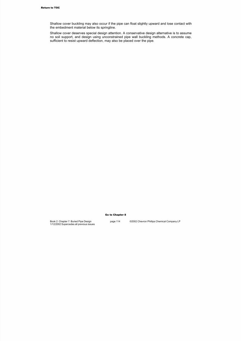
7/23/2019 The Performance Pipe Engineering Manual
http://slidepdf.com/reader/full/the-performance-pipe-engineering-manual 116/208
Book 2: Chapter 7: Buried Pipe Design page 114 ©2002 Chevron Phillips Chemical Company LP1/12/2002 Supercedes all previous issues
Shallow cover buckling may also occur if the pipe can float slightly upward and lose contact withthe embedment material below its springline.
Shallow cover deserves special design attention. A conservative design alternative is to assumeno soil support, and design using unconstrained pipe wall buckling methods. A concrete cap,sufficient to resist upward deflection, may also be placed over the pipe.
Go to Chapter 8
Return to TOC
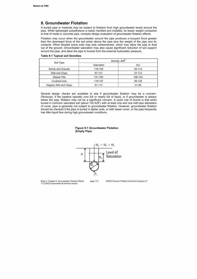
7/23/2019 The Performance Pipe Engineering Manual
http://slidepdf.com/reader/full/the-performance-pipe-engineering-manual 117/208
Book 2: Chapter 8: Groundwater Flotation Effects page 115 ©2002 Chevron Phillips Chemical Company LP1/12/2002 Supercedes all previous issues
8. Groundwater Flotation A buried pipe or manhole may be subject to flotation from high groundwater levels around thepipe. While lightweight polyethylene is easily handled and installed, its lesser weight comparedto that of metal or concrete pipe, compels design evaluation of groundwater flotation effects.
Flotation may occur when the groundwater around the pipe produces a buoyant force greater than the downward force of the soil prism above the pipe plus the weight of the pipe and itscontents. When flooded some soils may lose cohesiveness, which may allow the pipe to floatout of the ground. Groundwater saturation may also cause significant reduction of soil support
around the pipe, and allow the pipe to buckle from the external hydrostatic pressure .
Table 8-1 Typical soil Densities
Density, lb/ft 3
Soil TypeSaturated Dry
Sands and Gravels 118-150 93-114
Silts and Clays 87-131 37-112
Glacial Tills 131-150 106-144
Crushed rock 119-137 94-125
Organic Silts and Clays 81-112 31-94
Several design checks are available to see if groundwater flotation may be a concern.Obviously, if the pipeline typically runs full or nearly full of liquid, or if groundwater is alwaysbelow the pipe, flotation may not be a significant concern. A quick rule of thumb is that whenburied in common saturated soil (about 120 lb/ft3) with at least one and one half pipe diametersof cover, pipe is generally not subject to groundwater flotation. However, groundwater flotationshould be checked if the pipe is buried in lighter soils, or with lesser cover, or the pipe frequently
has little liquid flow during high groundwater conditions.
Figure 8-1 Groundwater Flotation
(Empty Pipe)
Return to TOC

7/23/2019 The Performance Pipe Engineering Manual
http://slidepdf.com/reader/full/the-performance-pipe-engineering-manual 118/208
Book 2: Chapter 8: Groundwater Flotation Effects page 116 ©2002 Chevron Phillips Chemical Company LP1/12/2002 Supercedes all previous issues
Groundwater Flotation of PipeFor 1 foot of an empty pipe, flotation will occur if
d f pb W W W F ++> (8-1)
Where
Fb = buoyant force, lb/ft
2
4OGb DF
π
ϖ = (8-2)
ωG = specific weight of groundwater, lb/ft3 (fresh water = 62.4 lb/ft3)(seawater = 64.0 lb/ft3)
DO = pipe outside diameter, ftWp = empty pipe weight, lb/ft
+
−−= sO
OGd f H D
DW
8
)4()(
2π
ω ω (8-3)
Wf = weight of flooded soil, lb/ftωd = specific weight of dry soil, lb/ft3 Hs = level of groundwater saturation above pipe, ftWd = weight of dry soil, lb/ft
Osd d DH H W )( −= ω (8-4)
H = height of cover above pipe, ftHs = level of groundwater saturation above pipe, ft
When an area is flooded, the soil particles are buoyed by their immersion in the liquid. Theeffective weight of flooded soil is the soil’s dry density less the density of the flooding liquid. For
example, a soil of 120 lb/ft3 dry density has an effective density of 57.6 lb/ft3 when completelyimmersed in fresh water (120 - 62.4 = 57.6 lb/ft3).
If the pipe contains a liquid, then the weight of the liquid will reduce the possibility of groundwater flotation. For 1 foot of pipe containing a liquid
Ld f pb W W W W F +++> (8-5)
Where
WL = weight of the liquid in the pipe, lb/ft
When a pipe is 100% full of liquid, the liquid weight is
4%100,I
LL
D
W
π
ω = (8-6)
And if 50% full, the liquid weight is
8%50,
I LL
DW
π
ω = (8-7)
Where
ωL = specific weight of the liquid in the pipe, lb/ft3
Return to TOC

7/23/2019 The Performance Pipe Engineering Manual
http://slidepdf.com/reader/full/the-performance-pipe-engineering-manual 119/208
Book 2: Chapter 8: Groundwater Flotation Effects page 117 ©2002 Chevron Phillips Chemical Company LP1/12/2002 Supercedes all previous issues
DI = pipe inside diameter, ft
For pipe liquid levels between empty and half-full (0% to 50%) or between half-full and full (50%to 100%) as illustrated in Figure 8-2, Formulas 8-8 and 8-9 provide an approximate liquid weightwith an accuracy of about ±10%.
For a liquid level between empty and half-full, the weight of the liquid in the pipe isapproximately
392.03
4 3
+−
=h
hDhW I
LL ω (8-8)
Where
h = liquid level in the pipe, ft
For a liquid level between half-full and full, the weight of the liquid in the pipe is approximately
−= e
I
LL h
D
W 573.14
2π
ω (8-9)
Where
he = height above liquid in pipe, ft
hDh I e −= (8-10)
Groundwater Flotation of ManholesCompared to pipe, manholes are less resistant to groundwater flotation because the manholeriser eliminates the soil prism load that exists above buried pipe. Under some groundwater conditions, the frictional resistance of the soil surrounding the manhole riser, and the soil prism
load over the manhole stub-outs may not be adequate to prevent flotation; so anti-flotationanchors may be required.
Anti-flotation anchors are reinforced concrete slabs that are placed above the manhole stub-outs. The anchors provide additional weight to counteract buoyant forces against the manholebase.
Anti-flotation anchors are installed beside the manhole shaft above the manhole stub-outs.
Figure 8-2 Pipe Liquid Level
Return to TOC
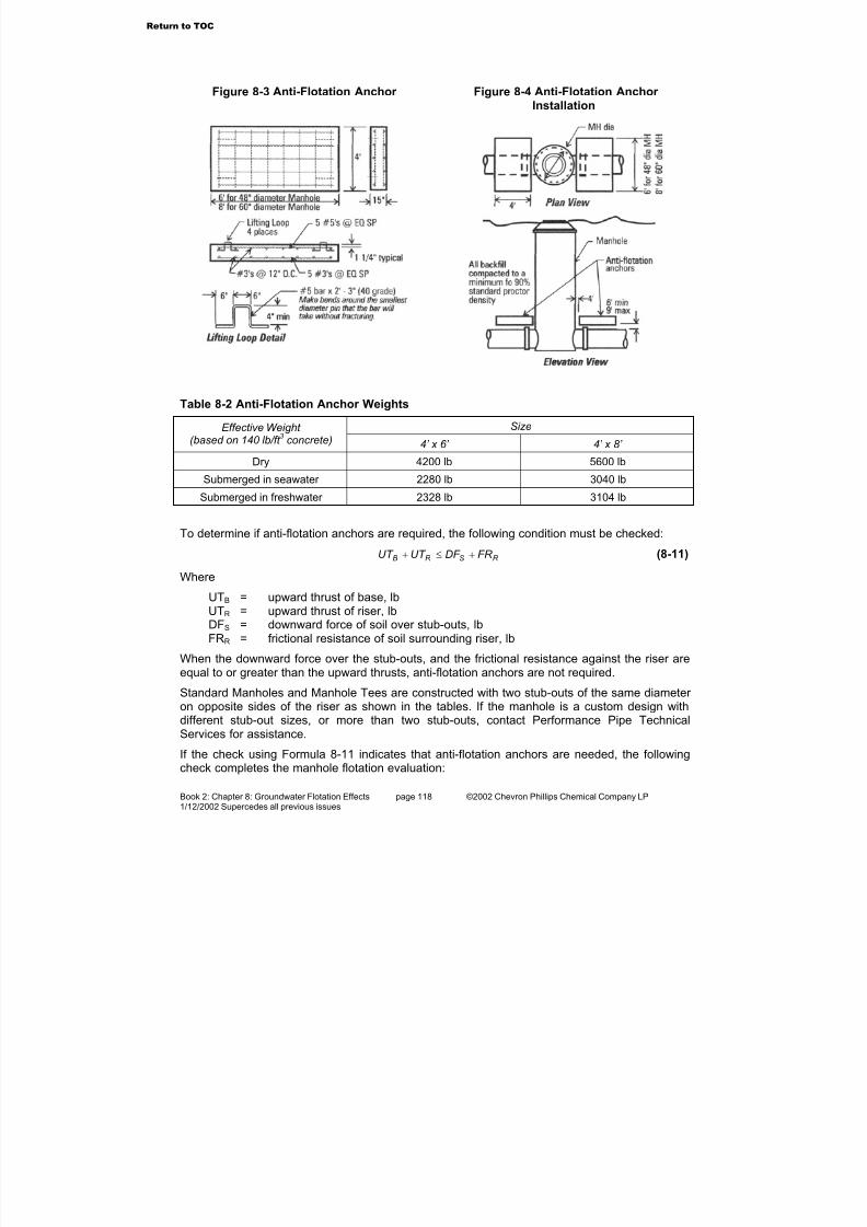
7/23/2019 The Performance Pipe Engineering Manual
http://slidepdf.com/reader/full/the-performance-pipe-engineering-manual 120/208
Book 2: Chapter 8: Groundwater Flotation Effects page 118 ©2002 Chevron Phillips Chemical Company LP1/12/2002 Supercedes all previous issues
Table 8-2 Anti-Flotation Anchor Weights
SizeEffective Weight (based on 140 lb/ft
3concrete) 4’ x 6’ 4’ x 8’
Dry 4200 lb 5600 lb
Submerged in seawater 2280 lb 3040 lb
Submerged in freshwater 2328 lb 3104 lb
To determine if anti-flotation anchors are required, the following condition must be checked:
R SR B FR DF UT UT +≤+ (8-11)
Where
UTB = upward thrust of base, lbUTR = upward thrust of riser, lbDFS = downward force of soil over stub-outs, lbFRR = frictional resistance of soil surrounding riser, lb
When the downward force over the stub-outs, and the frictional resistance against the riser areequal to or greater than the upward thrusts, anti-flotation anchors are not required.
Standard Manholes and Manhole Tees are constructed with two stub-outs of the same diameter on opposite sides of the riser as shown in the tables. If the manhole is a custom design withdifferent stub-out sizes, or more than two stub-outs, contact Performance Pipe TechnicalServices for assistance.
If the check using Formula 8-11 indicates that anti-flotation anchors are needed, the followingcheck completes the manhole flotation evaluation:
Figure 8-3 Anti-Flotation Anchor Figure 8-4 Anti-Flotation Anchor Installation
Return to TOC

7/23/2019 The Performance Pipe Engineering Manual
http://slidepdf.com/reader/full/the-performance-pipe-engineering-manual 121/208
Book 2: Chapter 8: Groundwater Flotation Effects page 119 ©2002 Chevron Phillips Chemical Company LP1/12/2002 Supercedes all previous issues
AR BA DF UT UT ≤+ (8-12)
Where
UTBA = upward thrust of anchored base, lbDF A = downward force of anti-flotation anchors, lb
Tables 8-3 through 8-9 have been developed for use with Formulas 8-11 and 8-12. Safetyfactors are included in table values and the default soil weight is 120 lb/ft 3. Soil weightmultipliers in Table 8-5 may be used to convert table values for lighter or heavier soils.
Table 8-3 Upward Thrust of Base, UTB
Stub-out Nominal Inside Diameter, in
Standard Manhole,48” Diameter Riser, lb
Manhole Tee, 48” Diameter Riser, lb
Standard Manhole,60” Diameter Riser, lb
Manhole Tee, 60” Diameter Riser, lb
18 1,475 – 1,793 –
21 1,839 – 2,194 –
24 2,240 – 2,630 –
27 2,678 – 3,099 –30 3,153 – 3,601 –
33 3,668 – 4,142 –
36 4,279 – 4,777 –
42 5,494 – 6,026 –
48 – 7,303 7,441 –
54 – 8,986 8,997 –
60 – 10,910 – 11,505
66 – 13,053 – 13,539
72 – 15,406 – 15,829
78 – 17,951 – 18,32984 – 20,739 – 21,082
Return to TOC

7/23/2019 The Performance Pipe Engineering Manual
http://slidepdf.com/reader/full/the-performance-pipe-engineering-manual 122/208
Book 2: Chapter 8: Groundwater Flotation Effects page 120 ©2002 Chevron Phillips Chemical Company LP1/12/2002 Supercedes all previous issues
Table 8-4 Riser Upward Thrust per VerticalFoot of Cover, UTB
% of Water toSurface
48” Diameter Riser, lb
60” Diameter Riser, lb
10 85 132
20 170 264
30 256 396
40 341 528
50 426 660
60 511 793
70 597 925
80 682 1057
90 767 1189
100 852 1321
Table 8-5 Soil Weight Multipliers
Soil Weight, lb/ft 3
Multiplier
140 1.17
130 1.08
110 0.92
100 0.83
90 0.75
Table 8-6 Soil Downward Force over TwoAnti-Flotation Anchors, DFA
4’ x 6’ Anchor 4’ x 8’ Anchor Cover Height Over
Stub-out, ft
Below Water,
lb
AboveWater,
lb
Below Water,
lb
AboveWater,
lb
2 2,304 4,800 3,072 6,400
3 4,608 9,600 6,144 12,800
4 6,912 14,400 9,216 19,200
5 9,216 19,200 12,288 25,600
6 11,520 24,000 15,360 32,000
7 13,824 28,800 18,432 38,400
8 16,128 33,600 21,504 44,800
9 18,432 38,400 24,576 51,200
10 20,736 43,700 27,648 57,600
12 25,344 52,800 33,792 70,400
14 29,952 62,400 39,936 83,200
16 34,560 72,000 46,080 96,000
18 39,168 81,600 52,224 108,800
20 43,776 91,200 58,368 121,600
22 48,384 100,800 64,512 134,400
24 52,992 110,400 70,656 147,200
26 67,600 120,000 76,800 160,000
Safety factor - 1.2; soil weight – 120 lb/ft3
Return to TOC
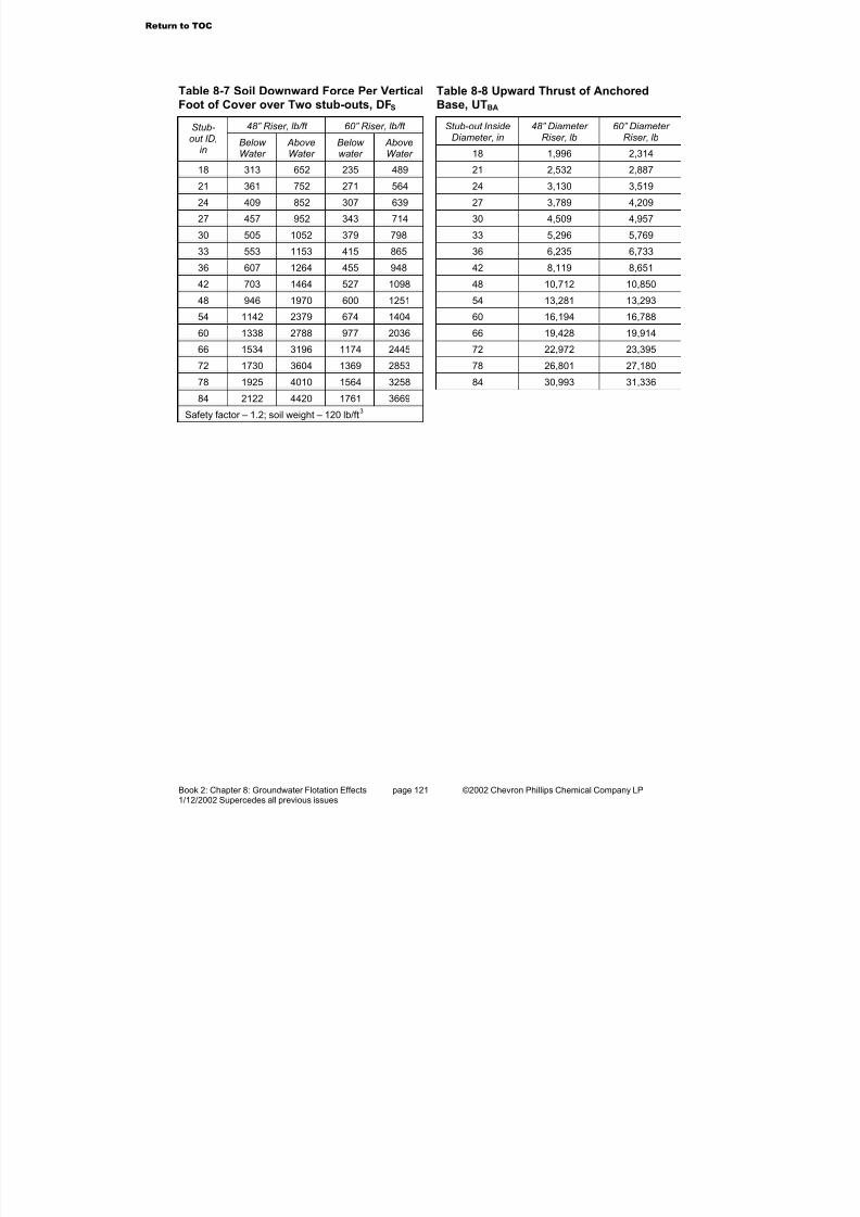
7/23/2019 The Performance Pipe Engineering Manual
http://slidepdf.com/reader/full/the-performance-pipe-engineering-manual 123/208
Book 2: Chapter 8: Groundwater Flotation Effects page 121 ©2002 Chevron Phillips Chemical Company LP1/12/2002 Supercedes all previous issues
Table 8-7 Soil Downward Force Per VerticalFoot of Cover over Two stub-outs, DFS
48” Riser, lb/ft 60” Riser, lb/ft Stub-out ID,
inBelow Water
AboveWater
Below water
AboveWater
18 313 652 235 489
21 361 752 271 564
24 409 852 307 639
27 457 952 343 714
30 505 1052 379 798
33 553 1153 415 865
36 607 1264 455 948
42 703 1464 527 1098
48 946 1970 600 1251
54 1142 2379 674 1404
60 1338 2788 977 2036
66 1534 3196 1174 2445
72 1730 3604 1369 2853
78 1925 4010 1564 3258
84 2122 4420 1761 3669
Safety factor – 1.2; soil weight – 120 lb/ft3
Table 8-8 Upward Thrust of AnchoredBase, UTBA
Stub-out InsideDiameter, in
48” Diameter Riser, lb
60” Diameter Riser, lb
18 1,996 2,314
21 2,532 2,887
24 3,130 3,519
27 3,789 4,209
30 4,509 4,957
33 5,296 5,769
36 6,235 6,733
42 8,119 8,651
48 10,712 10,850
54 13,281 13,293
60 16,194 16,788
66 19,428 19,914
72 22,972 23,395
78 26,801 27,180
84 30,993 31,336
Return to TOC

7/23/2019 The Performance Pipe Engineering Manual
http://slidepdf.com/reader/full/the-performance-pipe-engineering-manual 124/208
Book 2: Chapter 8: Groundwater Flotation Effects page 122 ©2002 Chevron Phillips Chemical Company LP1/12/2002 Supercedes all previous issues
Table 8-9 Frictional Resistance of soil Surrounding Riser for selected Cover Depths, FRS
Manhole with 48” Diameter Riser (for Manhole Tee, FR S = 0 lb)
5’ Cover 10’ Cover 15’ Cover 20’ Cover 25’ Cover Stub-
out ID,in
Below Water,
lb
AboveWater,
lb
Below Water,
lb
AboveWater,
lb
Below Water,
lb
AboveWater,
lb
Below Water,
lb
AboveWater,
lb
Below Water,
lb
AboveWater,
lb18 421 878 1,685 3,510 3,791 7,898 6,740 14,042 10,531 21,940
21 397 828 1,590 3,312 3,577 7,452 6,359 13,248 9,936 20,700
24 373 777 1,491 3,107 3,355 6,990 5,965 12,426 9,320 19,416
27 347 723 1,388 2,892 3,124 6,508 5,554 11,570 8,677 18,078
30 320 667 1,280 2,667 2,881 6,001 5,121 10,669 8,002 16,670
33 291 606 1,164 2,456 2,620 5,457 4,657 9,702 7,277 15,159
36 256 534 1,025 2,135 2,306 4,804 4,100 8,541 6,406 13,345
42 180 375 721 1,502 1,622 3,379 2,883 6,007 4,505 9,386
Manhole with 60” Diameter Riser (for Manhole Tee, FR S = 0 lb)
5’ Cover 10’ Cover 15’ Cover 20’ Cover 25’ Cover Stub-out ID,
in
Below Water,
lb
AboveWater,
lb
Below Water,
lb
AboveWater,
lb
Below Water,
lb
AboveWater,
lb
Below Water,
lb
AboveWater,
lb
Below Water,
lb
AboveWater,
lb
18 561 1,169 2,245 4,678 5,052 10,525 8,981 18,711 14,034 29,237
21 538 1,122 2,154 4,487 4,845 10,095 8,614 17,946 13,460 28,041
24 515 1,073 2,060 4,291 4,635 9,656 8,239 17,166 12,874 26,821
27 491 1,023 1,964 4,092 4,419 9,206 7,865 16,366 12,275 25,572
30 466 971 1,865 3,886 4,197 8,743 7,461 15,544 11,658 24,287
33 441 918 1,763 3,672 3,966 8,262 7,050 14,688 11,016 22,951
36 411 857 1,645 3,426 3,700 7,709 6,579 13,705 10,279 21,414
42 354 737 1,415 2,948 3,184 6,633 5,660 11,792 8,844 18,424
48 286 596 1,145 2,385 2,576 5,367 4,580 9,541 7,156 14,908
54 201 418 803 1,672 1,806 3,762 3,210 6,688 5,016 10,451
safety factor – 2.0; soil weight – 120 lb/ft3
Go to Chapter 9
Return to TOC

7/23/2019 The Performance Pipe Engineering Manual
http://slidepdf.com/reader/full/the-performance-pipe-engineering-manual 125/208
Book 2: Chapter 9: Water Environment Design page 123 ©2002 Chevron Phillips Chemical Company LP1/12/2002 Supercedes all previous issues
9. Water Environment Design ConsiderationsWater environment applications include any installation in a predominantly water environment,such as outfalls and intakes, river, lake, and stream crossings, floating and submergedpipelines, and wetland and marsh area installations. Further, applications such as sliplining may
require design consideration for external hydrostatic loads if the water table rises above theliner. Water environment design considerations include external hydraulic pressure,submergence weighting, and flotation at or above the surface.
External Hydraulic PressureFor the purposes of this discussion, unrestrained DRISCOPLEX™ OD controlled polyethylenepipes are freestanding pipes that are not encapsulated in backfill or encased in grout. Wheninstalled where continuous or occasional submergence may occur, such pipes may be causedto collapse if the external hydraulic pressure exceeds the flattening resistance of the pipe.
Flattening resistance should be considered for applications such as pipes carrying gases, pipespartially full of liquids, and any application where the internal pressure is less than the static
external hydraulic load.Flattening resistance usually is not a consideration for outfall and intake lines where the end of the pipe is open to the external water environment, or for water or wastewater lines crossingunder rivers, streams or lakes. Open ended lines will be pressure balanced, and the static headin a full pipe crossing a water body will usually be the same or higher than the water heightabove the pipeline.
Unconstrained Pipe Wall Buckling Excessive external pressure will cause flattening. The maximum external load is determined notby material strength, but by stiffness. The pipe will flatten if the bending moment due to the loadexceeds the resisting moment due to elastic stresses in the pipe. The critical external pressureabove which round pipe will flatten can be estimated with Love’s Equation:
3
2 1
1
1
2
−−=
DR
E P cr
µ
(9-1)
Where
PCR = critical flattening pressure, lb/in2 E = elastic modulus, lb/in2 (Table 5-1)µ = Poisson’s ratio
(0.45 for polyethylene under long-term stress)(0.35 for polyethylene under short-term stress)
DR = pipe dimension ratio
Pipe Ovality EffectsPipe deflection will reduce flattening resistance, and lower the critical flattening pressure. Thedesigner should apply an appropriate safety factor (2.0 or greater is typical).
cr O P N
f P = (9-2)
Where
Return to TOC
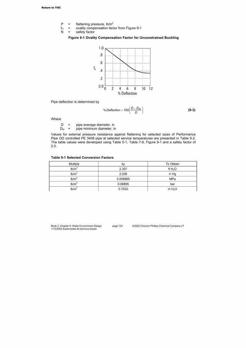
7/23/2019 The Performance Pipe Engineering Manual
http://slidepdf.com/reader/full/the-performance-pipe-engineering-manual 126/208
Book 2: Chapter 9: Water Environment Design page 124 ©2002 Chevron Phillips Chemical Company LP1/12/2002 Supercedes all previous issues
P = flattening pressure, lb/in2 f O = ovality compensation factor from Figure 9-1N = safety factor
Figure 9-1 Ovality Compensation Factor for Unconstrained Buckling
Pipe deflection is determined by
−=
D
DDDeflection M 100% (9-3)
Where
D = pipe average diameter, inDM = pipe minimum diameter, in
Values for external pressure resistance against flattening for selected sizes of PerformancePipe OD controlled PE 3408 pipe at selected service temperatures are presented in Table 9-2.
The table values were developed using Table 5-1, Table 7-9, Figure 9-1 and a safety factor of 2.0.
Table 9-1 Selected Conversion Factors
Multiply by To Obtain
lb/in2
2.307 ft H2O
lb/in2
2.036 in Hg
lb/in2
0.006895 MPa
lb/in2
0.06895 bar
lb/in2 0.7032 m H2O
Return to TOC
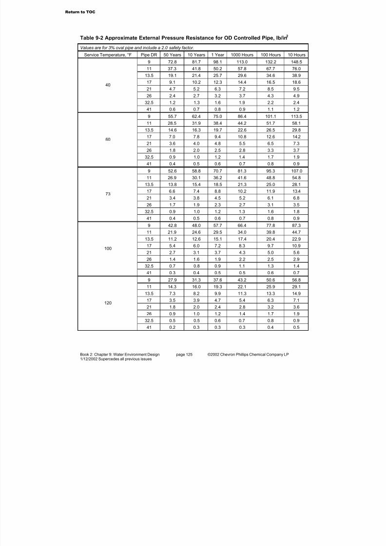
7/23/2019 The Performance Pipe Engineering Manual
http://slidepdf.com/reader/full/the-performance-pipe-engineering-manual 127/208
Book 2: Chapter 9: Water Environment Design page 125 ©2002 Chevron Phillips Chemical Company LP1/12/2002 Supercedes all previous issues
Table 9-2 Approximate External Pressure Resistance for OD Controlled Pipe, lb/in2
Values are for 3% oval pipe and include a 2.0 safety factor.
Service Temperature, °F Pipe DR 50 Years 10 Years 1 Year 1000 Hours 100 Hours 10 Hours
9 72.8 81.7 98.1 113.0 132.2 148.5
11 37.3 41.8 50.2 57.8 67.7 76.0
13.5 19.1 21.4 25.7 29.6 34.6 38.9
17 9.1 10.2 12.3 14.4 16.5 18.6
21 4.7 5.2 6.3 7.2 8.5 9.5
26 2.4 2.7 3.2 3.7 4.3 4.9
32.5 1.2 1.3 1.6 1.9 2.2 2.4
40
41 0.6 0.7 0.8 0.9 1.1 1.2
9 55.7 62.4 75.0 86.4 101.1 113.5
11 28.5 31.9 38.4 44.2 51.7 58.1
13.5 14.6 16.3 19.7 22.6 26.5 29.8
17 7.0 7.8 9.4 10.8 12.6 14.2
21 3.6 4.0 4.8 5.5 6.5 7.3
26 1.8 2.0 2.5 2.8 3.3 3.7
32.5 0.9 1.0 1.2 1.4 1.7 1.9
60
41 0.4 0.5 0.6 0.7 0.8 0.9
9 52.6 58.8 70.7 81.3 95.3 107.0
11 26.9 30.1 36.2 41.6 48.8 54.8
13.5 13.8 15.4 18.5 21.3 25.0 28.1
17 6.6 7.4 8.8 10.2 11.9 13.4
21 3.4 3.8 4.5 5.2 6.1 6.8
26 1.7 1.9 2.3 2.7 3.1 3.5
32.5 0.9 1.0 1.2 1.3 1.6 1.8
73
41 0.4 0.5 0.6 0.7 0.8 0.9
9 42.8 48.0 57.7 66.4 77.8 87.3
11 21.9 24.6 29.5 34.0 39.8 44.7
13.5 11.2 12.6 15.1 17.4 20.4 22.9
17 5.4 6.0 7.2 8.3 9.7 10.9
21 2.7 3.1 3.7 4.3 5.0 5.6
26 1.4 1.6 1.9 2.2 2.5 2.9
32.5 0.7 0.8 0.9 1.1 1.3 1.4
100
41 0.3 0.4 0.5 0.5 0.6 0.7
9 27.9 31.3 37.6 43.2 50.6 56.8
11 14.3 16.0 19.3 22.1 25.9 29.1
13.5 7.3 8.2 9.9 11.3 13.3 14.917 3.5 3.9 4.7 5.4 6.3 7.1
21 1.8 2.0 2.4 2.8 3.2 3.6
26 0.9 1.0 1.2 1.4 1.7 1.9
32.5 0.5 0.5 0.6 0.7 0.8 0.9
120
41 0.2 0.3 0.3 0.3 0.4 0.5
Return to TOC

7/23/2019 The Performance Pipe Engineering Manual
http://slidepdf.com/reader/full/the-performance-pipe-engineering-manual 128/208
Book 2: Chapter 9: Water Environment Design page 126 ©2002 Chevron Phillips Chemical Company LP1/12/2002 Supercedes all previous issues
Submergence Weighting A body submerged in a liquid displaces liquid equal to its volume. If the body weighs more thanthe weight of the liquid volume displaced, it will sink. If it weighs less, it will float.DRISCOPLEX™ polyethylene materials are lighter than water and pipe will float slightly abovethe surface when filled with water. Submerged pipe must be ballasted to keep it submerged.
Ballast weight design considers the fluids outside and inside the pipe, the liquid volumedisplaced, the weight of that displaced liquid volume, the weights of the submerged bodies(pipe, pipe contents, and ballast) and the environmental conditions.
Ballast Design for DRISCOPLEX™ OD Controlled Pipe
See Performance Pipe product literature for pipe dimensions and weights. The following is astep-by-step procedure for determining ballast weight for DRISCOPLEX™ OD controlled pipe.
Step 1
Determine volume of liquid displaced and buoyancy for one foot of pipe:
576
2D
V P
π
= (9-4)
LOP P K V B ω = (9-5)
Where
VP = displaced volume of pipe, ft3/ftD = pipe outside diameter, inBP = buoyancy of pipe, lb/ftK = environmental multiplier (Table 9-2)ωLO = specific weight of the liquid outside the pipe, lb/ft3
The environmental multiplier, K, compensates for the effects of tidal flows and currents. Unlessneutral buoyancy is desired, K should be greater than 1.0.
Table 9-3 Environmental Multiplier, K
Underwater Environment K
Neutral buoyancy 1.0
Lakes, ponds, slow moving streams or rivers, lowcurrents and tidal actions
1.3
Significant stream or rover currents or tidal flows 1.5
Table 9-4 presents specific weights for various liquids. For other liquids and slurries Formula 9-6may be used to calculate a specific weight when the specific gravity of the liquid is known. For this discussion, gasses (air, gas, carbon dioxide, etc.) in the pipe have a specific gravity of zerorelative to water.
LL S4.62=ω (9-6)
Where
ωL = specific weight of liquidSL = specific gravity of liquid
Return to TOC
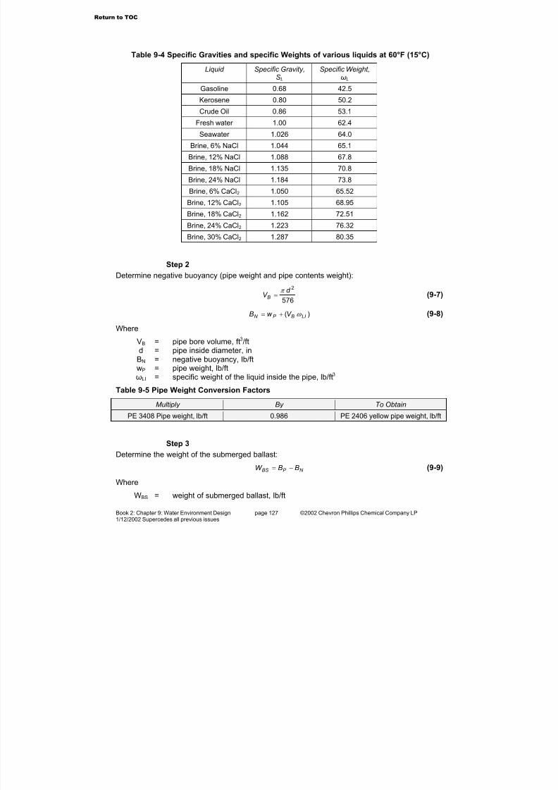
7/23/2019 The Performance Pipe Engineering Manual
http://slidepdf.com/reader/full/the-performance-pipe-engineering-manual 129/208
Book 2: Chapter 9: Water Environment Design page 127 ©2002 Chevron Phillips Chemical Company LP1/12/2002 Supercedes all previous issues
Table 9-4 Specific Gravities and specific Weights of various liquids at 60°F (15°C)
Liquid Specific Gravity,SL
Specific Weight,ωL
Gasoline 0.68 42.5
Kerosene 0.80 50.2
Crude Oil 0.86 53.1
Fresh water 1.00 62.4
Seawater 1.026 64.0
Brine, 6% NaCl 1.044 65.1
Brine, 12% NaCl 1.088 67.8
Brine, 18% NaCl 1.135 70.8
Brine, 24% NaCl 1.184 73.8
Brine, 6% CaCl2 1.050 65.52
Brine, 12% CaCl2 1.105 68.95
Brine, 18% CaCl2 1.162 72.51
Brine, 24% CaCl2 1.223 76.32
Brine, 30% CaCl2 1.287 80.35
Step 2
Determine negative buoyancy (pipe weight and pipe contents weight):
576
2d V B
π = (9-7)
)( LI BP N V w B ω += (9-8)
Where
VB = pipe bore volume, ft3/ftd = pipe inside diameter, in
BN = negative buoyancy, lb/ftwP = pipe weight, lb/ftωLI = specific weight of the liquid inside the pipe, lb/ft3
Table 9-5 Pipe Weight Conversion Factors
Multiply By To Obtain
PE 3408 Pipe weight, lb/ft 0.986 PE 2406 yellow pipe weight, lb/ft
Step 3
Determine the weight of the submerged ballast:
N P BS BBW −= (9-9)
Where
WBS = weight of submerged ballast, lb/ft
Return to TOC

7/23/2019 The Performance Pipe Engineering Manual
http://slidepdf.com/reader/full/the-performance-pipe-engineering-manual 130/208
Book 2: Chapter 9: Water Environment Design page 128 ©2002 Chevron Phillips Chemical Company LP1/12/2002 Supercedes all previous issues
Step 4
The designer must choose an appropriate ballast weight material (concrete, steel, etc.). For thechosen ballast weight material, determine the dry land weight required. Ballast weights areusually spaced every to 10-15 feet to avoid excessive pipe bending stresses during and after installation.
)( LOB
BBSBD
K W LW
ω ω
ω
−= (9-10)
Where
WBD = weight of dry ballast, lbL = ballast weight spacing, ftωB = specific weight of ballast material. lb/ft3
Weight Shapes
Submergence weights are frequently made of reinforced concrete, which allows considerableflexibility of shape design. Weights are typically formed in two or more sections that clamparound the pipe over an elastomeric padding material. There should be clearance between thesections, so when clamped onto the pipe, the sections do not slide along the pipe. In general,weights are flat bottom, and bottom heavy. This prevents rolling from crosscurrent conditions.Fasteners securing the weight sections together must be resistant to the marine environment.
Figure 9-2 Concrete Weight Figure 9-3 Concrete Weight
Go to Book 3: Chapter 1
Return to TOC

7/23/2019 The Performance Pipe Engineering Manual
http://slidepdf.com/reader/full/the-performance-pipe-engineering-manual 131/208
CPChem
a dia dia dia dia division of vision of vision of vision of vision of CheCheCheCheChevr vr vr vr vr on Phillips Chemical Companon Phillips Chemical Companon Phillips Chemical Companon Phillips Chemical Companon Phillips Chemical Company LPy LPy LPy LPy LP
PERFORMANCE PIPEPERFORMANCE PIPEPERFORMANCE PIPEPERFORMANCE PIPEPERFORMANCE PIPE
TM
©2002 Performance PipeTM
The Performance PipeTM
Engineering Manual
Book 3: System Installation
All rights reserved. This publicaiton is fully protected by copyright and nothing that appears in it may
be reprinted, copied, or otherwise reproduced by any means including electronic media, either wholly
or in part, without the express written permission of Performance PipeTM a division of Chevron Phillips
Chemical Company LP.
NOTICE -- This Manual is intended to be used as a guide to support the designer of polyethylene
piping systems. It is not intended to be used as installation instructions, and should not be substi-
tuted in place of the advice of a professional design engineer. There may be a more current version
of this manual. Contact Performance PipeTM for more informantion.
PLEXCO, PLEXVUE, and YELLOWSTRIPE are registered trademarks of Chevron Phillips
Chemical Company LP in the United States of America; BLUESTRIPE, CP CHEM, DRISCOPLEX,
GREENSTRIPE, PERFORMANCE PIPE, PLEXCO BLUESTRIPE, PLEXSHIELD, PLEXSTRIPE,
PURPLESTRIPE, REDSTRIPE, and SPIROLITE are trademarks of Chevron Phillips Chemical
Company LP in the United States of America.
Return to TOC
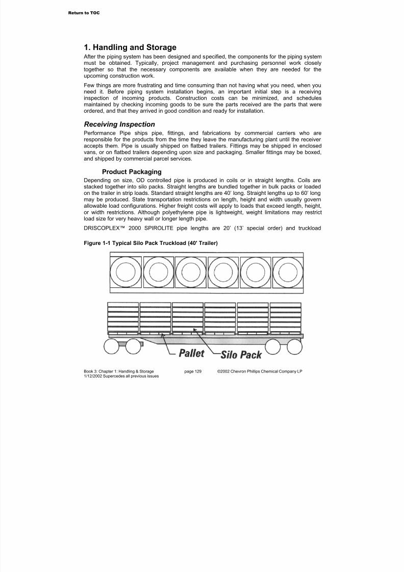
7/23/2019 The Performance Pipe Engineering Manual
http://slidepdf.com/reader/full/the-performance-pipe-engineering-manual 132/208
Book 3: Chapter 1: Handling & Storage page 129 ©2002 Chevron Phillips Chemical Company LP1/12/2002 Supercedes all previous issues
1. Handling and Storage After the piping system has been designed and specified, the components for the piping systemmust be obtained. Typically, project management and purchasing personnel work closelytogether so that the necessary components are available when they are needed for the
upcoming construction work.Few things are more frustrating and time consuming than not having what you need, when youneed it. Before piping system installation begins, an important initial step is a receivinginspection of incoming products. Construction costs can be minimized, and schedulesmaintained by checking incoming goods to be sure the parts received are the parts that wereordered, and that they arrived in good condition and ready for installation.
Receiving InspectionPerformance Pipe ships pipe, fittings, and fabrications by commercial carriers who areresponsible for the products from the time they leave the manufacturing plant until the receiver accepts them. Pipe is usually shipped on flatbed trailers. Fittings may be shipped in enclosed
vans, or on flatbed trailers depending upon size and packaging. Smaller fittings may be boxed,and shipped by commercial parcel services.
Product Packaging
Depending on size, OD controlled pipe is produced in coils or in straight lengths. Coils arestacked together into silo packs. Straight lengths are bundled together in bulk packs or loadedon the trailer in strip loads. Standard straight lengths are 40’ long. Straight lengths up to 60’ longmay be produced. State transportation restrictions on length, height and width usually governallowable load configurations. Higher freight costs will apply to loads that exceed length, height,or width restrictions. Although polyethylene pipe is lightweight, weight limitations may restrictload size for very heavy wall or longer length pipe.
DRISCOPLEX™ 2000 SPIROLITE pipe lengths are 20’ (13’ special order) and truckload
Figure 1-1 Typical Silo Pack Truckload (40' Trailer)
Return to TOC
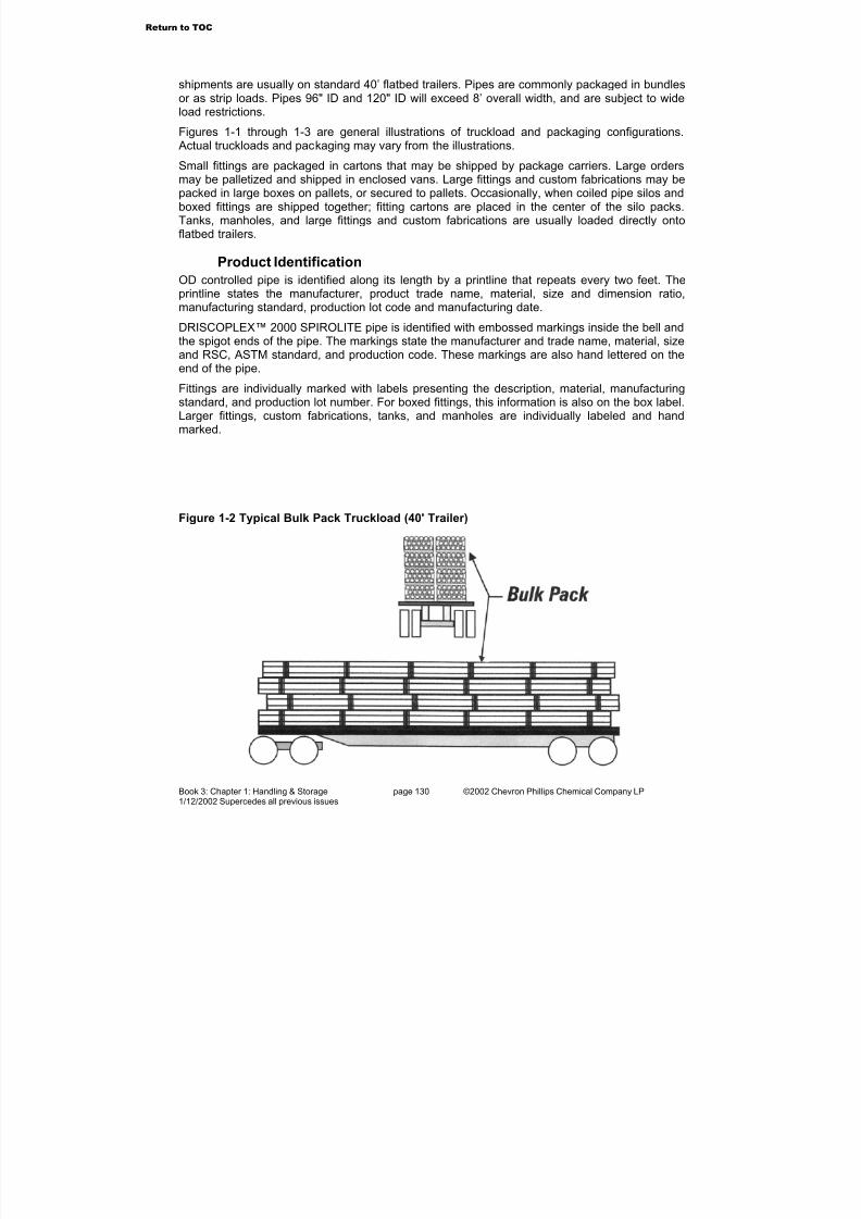
7/23/2019 The Performance Pipe Engineering Manual
http://slidepdf.com/reader/full/the-performance-pipe-engineering-manual 133/208
Book 3: Chapter 1: Handling & Storage page 130 ©2002 Chevron Phillips Chemical Company LP1/12/2002 Supercedes all previous issues
shipments are usually on standard 40’ flatbed trailers. Pipes are commonly packaged in bundlesor as strip loads. Pipes 96" ID and 120" ID will exceed 8’ overall width, and are subject to wideload restrictions.
Figures 1-1 through 1-3 are general illustrations of truckload and packaging configurations. Actual truckloads and packaging may vary from the illustrations.
Small fittings are packaged in cartons that may be shipped by package carriers. Large ordersmay be palletized and shipped in enclosed vans. Large fittings and custom fabrications may bepacked in large boxes on pallets, or secured to pallets. Occasionally, when coiled pipe silos andboxed fittings are shipped together; fitting cartons are placed in the center of the silo packs.Tanks, manholes, and large fittings and custom fabrications are usually loaded directly ontoflatbed trailers.
Product Identification
OD controlled pipe is identified along its length by a printline that repeats every two feet. Theprintline states the manufacturer, product trade name, material, size and dimension ratio,manufacturing standard, production lot code and manufacturing date.
DRISCOPLEX™ 2000 SPIROLITE pipe is identified with embossed markings inside the bell andthe spigot ends of the pipe. The markings state the manufacturer and trade name, material, sizeand RSC, ASTM standard, and production code. These markings are also hand lettered on theend of the pipe.
Fittings are individually marked with labels presenting the description, material, manufacturingstandard, and production lot number. For boxed fittings, this information is also on the box label.Larger fittings, custom fabrications, tanks, and manholes are individually labeled and handmarked.
Figure 1-2 Typical Bulk Pack Truckload (40' Trailer)
Return to TOC
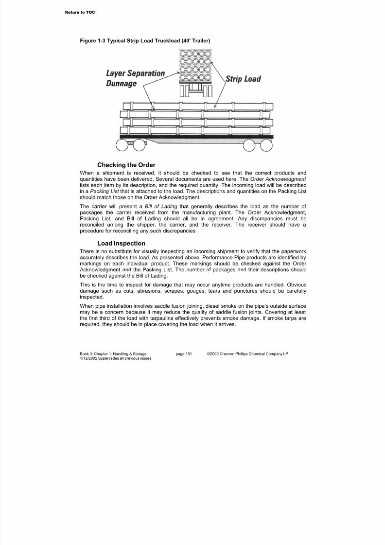
7/23/2019 The Performance Pipe Engineering Manual
http://slidepdf.com/reader/full/the-performance-pipe-engineering-manual 134/208
Book 3: Chapter 1: Handling & Storage page 131 ©2002 Chevron Phillips Chemical Company LP1/12/2002 Supercedes all previous issues
Checking the Order
When a shipment is received, it should be checked to see that the correct products andquantities have been delivered. Several documents are used here. The Order Acknowledgment lists each item by its description, and the required quantity. The incoming load will be describedin a Packing List that is attached to the load. The descriptions and quantities on the Packing Listshould match those on the Order Acknowledgment.
The carrier will present a Bill of Lading that generally describes the load as the number of packages the carrier received from the manufacturing plant. The Order Acknowledgment,
Packing List, and Bill of Lading should all be in agreement. Any discrepancies must bereconciled among the shipper, the carrier, and the receiver. The receiver should have aprocedure for reconciling any such discrepancies.
Load Inspection
There is no substitute for visually inspecting an incoming shipment to verify that the paperworkaccurately describes the load. As presented above, Performance Pipe products are identified bymarkings on each individual product. These markings should be checked against the Order Acknowledgment and the Packing List. The number of packages and their descriptions shouldbe checked against the Bill of Lading.
This is the time to inspect for damage that may occur anytime products are handled. Obviousdamage such as cuts, abrasions, scrapes, gouges, tears and punctures should be carefullyinspected.
When pipe installation involves saddle fusion joining, diesel smoke on the pipe’s outside surfacemay be a concern because it may reduce the quality of saddle fusion joints. Covering at leastthe first third of the load with tarpaulins effectively prevents smoke damage. If smoke tarps arerequired, they should be in place covering the load when it arrives.
Figure 1-3 Typical Strip Load Truckload (40' Trailer)
Return to TOC
7/23/2019 The Performance Pipe Engineering Manual
http://slidepdf.com/reader/full/the-performance-pipe-engineering-manual 135/208
Book 3: Chapter 1: Handling & Storage page 132 ©2002 Chevron Phillips Chemical Company LP1/12/2002 Supercedes all previous issues
Receiving Report & Reporting Damage
The delivering truck driver will ask the person receiving the shipment to sign the Bill of Lading,and acknowledge that the load was received in good condition. Any damage, missingpackages, etc., should be noted on the bill of lading at that time.
Shipping problems such as damage, missing packages, document discrepancies, incorrect
product, etc., should be reported to Performance Pipe Customer Service immediately. Shippingclaims must be filed within 7 days.
Unloading InstructionsUnloading and handling must be performed safely. Unsafe handling can result indamage to property or equipment, and can be hazardous to persons in the area. Keepunnecessary persons away from the area while unloading.
Observe unloading and handling instructions that are supplied with the load and available from the driver.
Before unloading the shipment, there must be adequate, level space to unload theshipment. The truck should be on level ground with the parking brake set and the wheelschocked. Unloading equipment must be capable of safely lifting and moving pipe,fittings, fabrications or other components.
Unloading Site Requirements
The unloading site must be relatively flat and level. It must be large enough for the carrier’struck, the load handling equipment and its movement, and for temporary load storage. Silopacks and other palletized packages should be unloaded from the side with a forklift. Non-palletized pipe, fittings, fabrications, manholes, tanks, or other components should be unloadedfrom above with lifting equipment and wide web slings, or from the side with a forklift.
Handling Equipment
Appropriate unloading and handling equipment of adequate capacity must be used tounload the truck, and safe handling and operating procedures must be followed.
Pipe must not be rolled or pushed off the truck. Pipe, fittings, fabrications, tanks,manholes, and other components must not be pushed or dumped off the truck, or dropped.
Although polyethylene piping components are lightweight compared to similar componentsmade of metal, concrete, clay, or other materials, larger components can be heavy. Lifting andhandling equipment must have adequate rated capacity to lift and move components from thetruck to temporary storage. Equipment such as a forklift, a crane, a side boom tractor, or anextension boom crane is used for unloading.
Return to TOC
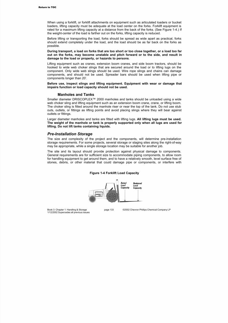
7/23/2019 The Performance Pipe Engineering Manual
http://slidepdf.com/reader/full/the-performance-pipe-engineering-manual 136/208
Book 3: Chapter 1: Handling & Storage page 133 ©2002 Chevron Phillips Chemical Company LP1/12/2002 Supercedes all previous issues
When using a forklift, or forklift attachments on equipment such as articulated loaders or bucketloaders, lifting capacity must be adequate at the load center on the forks. Forklift equipment israted for a maximum lifting capacity at a distance from the back of the forks. (See Figure 1-4.) If the weight-center of the load is farther out on the forks, lifting capacity is reduced.
Before lifting or transporting the load, forks should be spread as wide apart as practical, forks
should extend completely under the load, and the load should be as far back on the forks aspossible.
During transport, a load on forks that are too short or too close together, or a load too far out on the forks, may become unstable and pitch forward or to the side, and result indamage to the load or property, or hazards to persons.
Lifting equipment such as cranes, extension boom cranes, and side boom tractors, should behooked to wide web choker slings that are secured around the load or to lifting lugs on thecomponent. Only wide web slings should be used. Wire rope slings and chains can damagecomponents, and should not be used. Spreader bars should be used when lifting pipe or components longer than 20’.
Before use, inspect slings and lifting equipment. Equipment with wear or damage that
impairs function or load capacity should not be used.
Manholes and Tanks
Smaller diameter DRISCOPLEX™ 2000 manholes and tanks should be unloaded using a wideweb choker sling and lifting equipment such as an extension boom crane, crane, or lifting boom.The choker sling is fitted around the manhole riser or near the top of the tank. Do not use stubouts, outlets, or fittings as lifting points and avoid placing slings where they will bear againstoutlets or fittings.
Larger diameter manholes and tanks are fitted with lifting lugs. All lifting lugs must be used.The weight of the manhole or tank is properly supported only when all lugs are used for lifting. Do not lift tanks containing liquids.
Pre-Installation StorageThe size and complexity of the project and the components, will determine pre-installationstorage requirements. For some projects, several storage or staging sites along the right-of-waymay be appropriate, while a single storage location may be suitable for another job.
The site and its layout should provide protection against physical damage to components.General requirements are for sufficient size to accommodate piping components, to allow roomfor handling equipment to get around them, and to have a relatively smooth, level surface free of stones, debris, or other material that could damage pipe or components, or interfere with
Figure 1-4 Forklift Load Capacity
Return to TOC

7/23/2019 The Performance Pipe Engineering Manual
http://slidepdf.com/reader/full/the-performance-pipe-engineering-manual 137/208
Book 3: Chapter 1: Handling & Storage page 134 ©2002 Chevron Phillips Chemical Company LP1/12/2002 Supercedes all previous issues
handling. Pipe may be placed on 4-inch wide wooden dunnage, evenly spaced at intervals of 4feet or less.
Pipe Stacking Heights
Coiled pipe is best stored as received in silo packs. Individual coils may be removed from the
silo pack without disturbing the stability of the package.Pipe received in bulk packs or strip load packs should be stored in the same package. If thestorage site is flat and level, bulk packs or strip load packs may be stacked evenly upon eachother to an overall height of about 6’. For less flat or less level terrain, limit stacking height toabout 4’.
Before removing individual pipe lengths from bulk packs or strip load packs, the packmust be removed from the storage stack and placed on the ground.
Individual pipes may be stacked in rows. Pipes should be laid straight, not crossing over or entangled with each other. The base row must be blocked to prevent sideways movementor shifting. (See Figure 1-5; Table 1-1 and Table 1-2.)
The interior of stored pipe should be kept free of debris and other foreign matter.
Figure 1-5 Loose Pipe Storage
Return to TOC
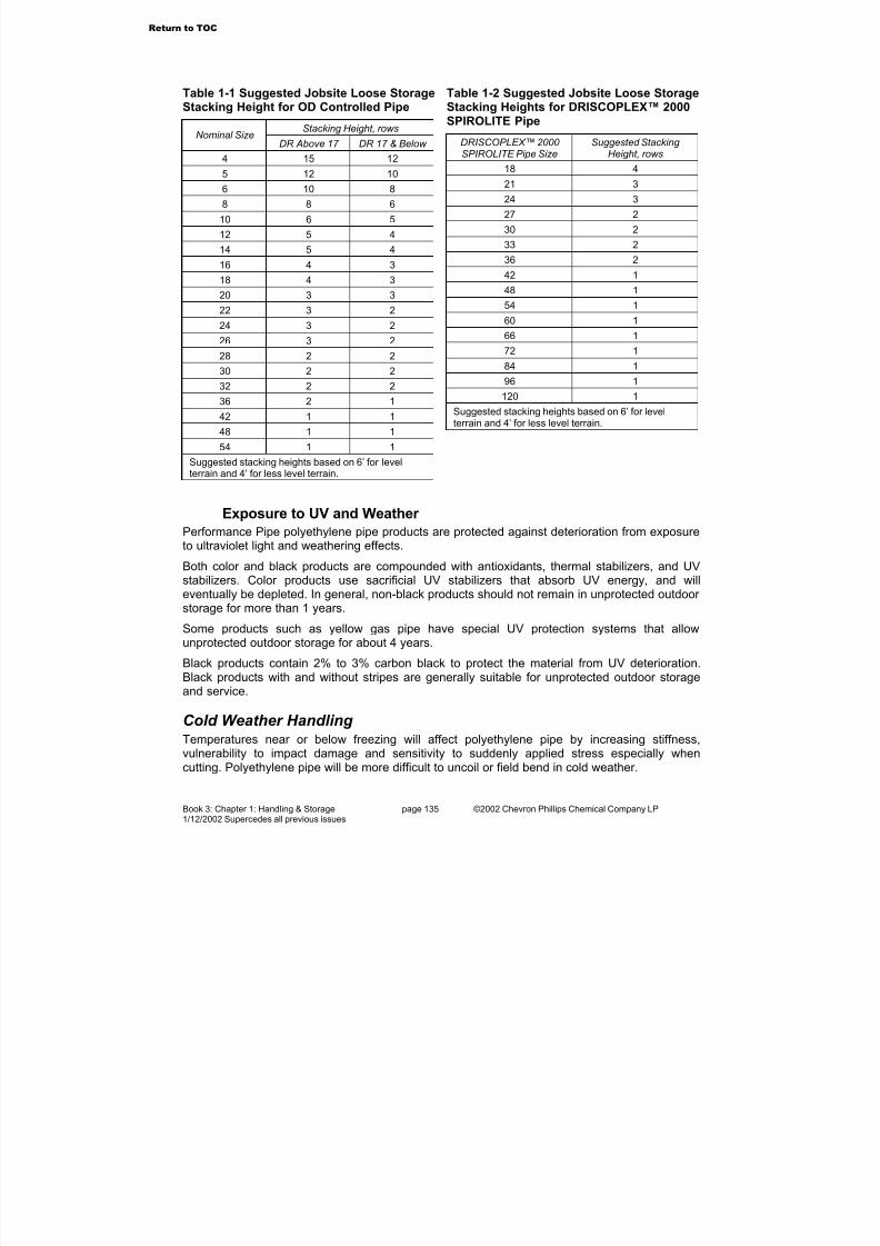
7/23/2019 The Performance Pipe Engineering Manual
http://slidepdf.com/reader/full/the-performance-pipe-engineering-manual 138/208
Book 3: Chapter 1: Handling & Storage page 135 ©2002 Chevron Phillips Chemical Company LP1/12/2002 Supercedes all previous issues
Exposure to UV and Weather
Performance Pipe polyethylene pipe products are protected against deterioration from exposureto ultraviolet light and weathering effects.
Both color and black products are compounded with antioxidants, thermal stabilizers, and UVstabilizers. Color products use sacrificial UV stabilizers that absorb UV energy, and willeventually be depleted. In general, non-black products should not remain in unprotected outdoor storage for more than 1 years.
Some products such as yellow gas pipe have special UV protection systems that allowunprotected outdoor storage for about 4 years.
Black products contain 2% to 3% carbon black to protect the material from UV deterioration.
Black products with and without stripes are generally suitable for unprotected outdoor storageand service.
Cold Weather Handling Temperatures near or below freezing will affect polyethylene pipe by increasing stiffness,vulnerability to impact damage and sensitivity to suddenly applied stress especially whencutting. Polyethylene pipe will be more difficult to uncoil or field bend in cold weather.
Table 1-1 Suggested Jobsite Loose StorageStacking Height for OD Controlled Pipe
Stacking Height, rowsNominal Size
DR Above 17 DR 17 & Below
4 15 12
5 12 10
6 10 8
8 8 6
10 6 5
12 5 4
14 5 4
16 4 3
18 4 3
20 3 3
22 3 2
24 3 2
26 3 2
28 2 2
30 2 2
32 2 2
36 2 1
42 1 1
48 1 1
54 1 1
Suggested stacking heights based on 6’ for levelterrain and 4’ for less level terrain.
Table 1-2 Suggested Jobsite Loose StorageStacking Heights for DRISCOPLEX™ 2000SPIROLITE Pipe
DRISCOPLEX™ 2000 SPIROLITE Pipe Size
Suggested Stacking Height, rows
18 4
21 3
24 3
27 2
30 2
33 2
36 2
42 1
48 1
54 1
60 1
66 172 1
84 1
96 1
120 1
Suggested stacking heights based on 6’ for levelterrain and 4’ for less level terrain.
Return to TOC
7/23/2019 The Performance Pipe Engineering Manual
http://slidepdf.com/reader/full/the-performance-pipe-engineering-manual 139/208
Book 3: Chapter 1: Handling & Storage page 136 ©2002 Chevron Phillips Chemical Company LP1/12/2002 Supercedes all previous issues
Significant impact or shock loads against a polyethylene pipe that is at freezing or lower temperatures can fracture the pipe.
• Do not drop pipe. Do not allow pipe to fall off the truck or into the trench.
• Do not strike the pipe with handling equipment, tools or other objects.
•
Do not drag pipe lengths at speeds where bouncing against the surface may causeimpact damage.
Pipe should be firmly supported on both sides when cutting with a handsaw. Low temperaturecan cause the pipe to split at the cut if bending stress is applied.
Ice, snow, and rain are not harmful to the material, but may make storage areas moretroublesome for handling equipment and personnel. Unsure footing and traction require greater care and caution to prevent damage or injury.
Performance Pipe cautions against walking on pipe at any time. In particular, inclementweather can make pipe surfaces especially slippery. Do not walk on pipe when footing isunsure.
Go to Chapter 2
Return to TOC

7/23/2019 The Performance Pipe Engineering Manual
http://slidepdf.com/reader/full/the-performance-pipe-engineering-manual 140/208
Book 3: Chapter 2: Joining & Connections page 137 ©2002 Chevron Phillips Chemical Company LP1/12/2002 Supercedes all previous issues
2. Joining & ConnectionsFor satisfactory material and product performance, system designs and installation methods relyon appropriate, properly made connections. An inadequate or improperly made field joint maycause installation delays, may disable or impair system operations, or may create hazardous
conditions.Performance Pipe Polyethylene Piping Products are connected using heat fusion, electrofusion,thermal welding, and mechanical methods such as gasketed bell-and-spigot joints, flanges, andcompression couplings. Joining and connection methods will vary depending upon requirementsfor internal or external pressure, leak tightness, restraint against longitudinal movement (thrustload capacity), gasketing requirements, construction and installation requirements, and theproduct.
WARNING – Connection design limitations and manufacturer’s joining procedures mustbe observed. Otherwise, the connection or products adjacent to the connection may leakor fail which may result in property damage, or hazards to persons.
Correctly made fusion joints do not leak. Leakage at a joint or connection may
immediately precede catastrophic failure. Never approach or attempt to repair or stopleaks while piping is pressurized. Always depressurize piping before making repairs.
Performance Pipe recommends using the tools and components required to constructand install joints in accordance with manufacturer’s recommendations. However, fieldconnections are controlled by, and are the responsibility of the field installer.
General Procedures All field connection methods and procedures require that the component ends to be connectedmust be clean, dry, and free of detrimental surface defects before the connection is made.Contamination and unsuitable surface conditions usually produce an unsatisfactory connection.Gasketed joints require appropriate lubrication.
Cleaning
Before joining, and before any special surface preparation, surfaces must be clean and dry.General dust and light soil may be removed by wiping the surfaces with clean, dry, lint freecloths. Heavier soil may be washed or scrubbed off with soap and water solutions, followed bythorough rinsing with clear water, and drying with dry, clean, lint-free cloths.
Before using chemical cleaning solvents, the user should know the potential risks andhazards to persons, and appropriate safety precautions must be taken. Chemicalsolvents may be hazardous substances that may require special handling and personalprotective equipment.
The manufacturer’s instructions for use, and the material safety data sheet (MSDS) for the
chemical should be consulted for information on risks to persons and for safe handling and useprocedures. Some solvents may leave a residue on the pipe. Information on chemicalcompatibility with polyethylene may be found in the Performance Pipe Engineering Manual,Book 1 Engineering Properties or in other sources.
Cutting DRISCOPLEX™ OD controlled Pipe
Joining methods for plain end pipe require square-cut ends. Pipe cutting is accomplished withguillotine shears, run-around cutters and saws. Before cutting, provide firm support on both
Return to TOC

7/23/2019 The Performance Pipe Engineering Manual
http://slidepdf.com/reader/full/the-performance-pipe-engineering-manual 141/208
Book 3: Chapter 2: Joining & Connections page 138 ©2002 Chevron Phillips Chemical Company LP1/12/2002 Supercedes all previous issues
sides.
Guillotine shears are commonly available for 2" and smaller pipe and tubing, and mayincorporate a ratcheting mechanism to drive the blade through the pipe. Run-around pipecutters are equipped with deep, narrow cutter wheels, and because of wall thickness, areusually limited to about 4" pipe. Care should be taken to avoid cutting a spiral groove around the
pipe. Guillotine and run-around cutters provide a clean cut without chips.For larger diameters, handsaws and chain saws are used. Coarse tooth handsaws providegreater chip clearance between the teeth, and maintain a clean blade when cutting. Chain sawsare usually operated without chain lubrication because chain oil contamination will need to beremoved from the pipe. Therefore, chain and bar life is reduced, but polyethylene is relativelysoft and non-abrasive, so saw chains stay sharp longer. Some installers may dedicate a dry-chain, chain saw for polyethylene pipe cutting. Bucking spikes should be removed.
Saws will produce chips that must be removed from the pipe bore and cleared from the jobsite.Pipe ends may require deburring.
Cutting DRISCOPLEX™ 2000 SPIROLITE Pipe
DRISCOPLEX™ 2000 SPIROLITE pipe is usually joined using a gasketed bell-and-spigotsystem. Pipe is manufactured with a formed bell and a machined spigot as an integral part of each length. Therefore, cutting DRISCOPLEX™ 2000 SPIROLITE profile wall pipe to lengthin the field is not recommended. When a non-standard field length is required,DRISCOPLEX™ 2000 SPIROLITE Closure Pipe is used with a closure bell and a special gasketto make the final connection.
DRISCOPLEX™ 2000 SPIROLITE Closure Pipe has a smooth OD and ID, and may be field cutto length using a handsaw or chain saw. Take care to provide a smooth, square cut end.
The DRISCOPLEX™ 2000 SPIROLITE Closure Pipe System is incorporated into standardDRISCOPLEX™ 2000 SPIROLITE Manholes and Manhole Tees. It is also available for straightpiping runs without manholes.
Cutting Branch Outlet Holes
With the exception of self-tapping saddle tees, hole cutting will be required for field installed sideoutlet fittings. Commercial hole saws for metals are generally unsatisfactory for polyethylenebecause they do not provide adequate chip clearance, and may not be deep enough for the wallthickness. Polyethylene pipe hole saws are deep shell cutters with very few teeth, large chipclearance, and inside relief to retain the coupon. Polyethylene pipe joining equipmentmanufacturers should be contacted for additional information on hole saws.
When cutting, hole saws should be withdrawn frequently to clear the chips. Powered hole sawsshould be operated at relatively low speeds to avoid overheating and melting the material.
Fully Restrained ConnectionsHeat Fusion Joining
Please see Performance Pipe Bulletin PP-750 Fusion Joining Procedures.
Performance Pipe Fusion Joining Procedures should be reviewed before making heatfusion joints, and should be observed when making heat fusion joints withDRISCOPLEX™ OD controlled polyethylene piping products. ASTM D 2657, Standard Practice for Heat-Joining Polyolefin Pipe and Fittings, and ASTM F 905, Standard Practice for
Return to TOC
7/23/2019 The Performance Pipe Engineering Manual
http://slidepdf.com/reader/full/the-performance-pipe-engineering-manual 142/208
Book 3: Chapter 2: Joining & Connections page 139 ©2002 Chevron Phillips Chemical Company LP1/12/2002 Supercedes all previous issues
Qualification of Saddle Fusion Joints provide general information on heat fusion joining.
Heat fusion joining is a process where mating surfaces are prepared for joining, heated untilmolten, joined together and cooled under pressure. All fusion procedures require appropriatesurface preparation tools, alignment tools, and temperature controlled heating irons withproperly shaped, non-stick heater faces. An open flame cannot be used for heating because it
oxidizes the surface and prevents bonding. During joining, all heat fusion procedures require themating components to be moved several inches apart to accommodate surface preparation andsurface heating tools.
Socket fusion joins a male pipe or fitting end into a female socket fitting. Saddle fusion joins acurved base, branch outlet to the side of a pipe. Butt fusion joins plain end pipe or fittings endto end. Heat fusion joining procedures do not add material to the joint; that is, no welding rods,adhesives, or cements are used.
Heat fusion joints made between appropriate products using appropriate equipment andrecommended procedures are fully restrained, permanent joints. That is, the joints may beexpected to last the life of the system, and to withstand thrust loads equal to the strength of thepipe without adding external restraint or thrust blocking.
In some circumstances, polyethylene pipe or fittings may be exposed to internal or externalchemicals such as hydrocarbons, which may permeate polyethylene. Liquid hydrocarbonpermeated polyethylene pipes should not be joined using heat fusion. Permeatingchemicals may vaporize during heating, contaminate the bonding area and cause a low qualitybond.
Heat fusion tools should be inspected before use, and if found to be defective, the tools shouldbe repaired or replaced before making joints. Once made, heat fusion joints should beinspected, and if found to be faulty, the unsatisfactory joint should be removed from the system.
Faulty socket or butt fusions must be cut out and re-done. Faulty saddle fusions may becut out, or the saddle fitting may be cut off above the base to prevent use. Faulty heatfusion joints cannot be repaired, and socket and saddle fusion fittings cannot be re-used.Butt fittings outlets are usually long enough to allow a second fusion if the first fusion is carefullycut out.
Socket Fusion
Socket fusion is used with 1/2" through 4" DRISCOPLEX™ OD controlled Pipe and Fittings.Socket fusion fittings are manufactured to ASTM D 2683, Socket-Type Polyethylene Fittings for Outside Diameter-Controlled Polyethylene Pipe and Tubing . Pipe and tubing must bemanufactured to OD controlled pipe or tubing specifications. Socket fusion heater faces aremanufactured to ASTM F 1056, Standard Specification for Socket Fusion Tools for Use inSocket Fusion Joining Polyethylene Pipe or Tubing and Fittings.
Field socket fusion tools are hand-held, and for 3" and 4" sizes, two persons are usually neededto make joints.
Saddle Fusion
When used as a field procedure, saddle fusion branch outlets are usually 8" IPS and smaller,and are applied to pipe sizes 12" IPS and smaller. Larger outlets and pipe sizes are available asfactory-made fabricated fittings.
Table 3-1, below, is a general reference to the size limitations of field saddle fusion. Please refer to Performance Pipe product literature for size and availability of saddle fusion fittings. Someindustries and applications are better equipped for saddle fusion than others. For example, gas
Return to TOC
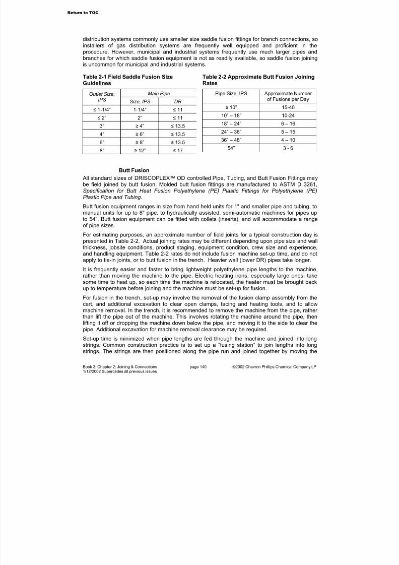
7/23/2019 The Performance Pipe Engineering Manual
http://slidepdf.com/reader/full/the-performance-pipe-engineering-manual 143/208
Book 3: Chapter 2: Joining & Connections page 140 ©2002 Chevron Phillips Chemical Company LP1/12/2002 Supercedes all previous issues
distribution systems commonly use smaller size saddle fusion fittings for branch connections, soinstallers of gas distribution systems are frequently well equipped and proficient in theprocedure. However, municipal and industrial systems frequently use much larger pipes andbranches for which saddle fusion equipment is not as readily available, so saddle fusion joiningis uncommon for municipal and industrial systems.
Table 2-1 Field Saddle Fusion SizeGuidelines
Main PipeOutlet Size,IPS Size, IPS DR
≤ 1-1/4” 1-1/4” ≤ 11
≤ 2” 2” ≤ 11
3” ≥ 4” ≤ 13.5
4” ≥ 6” ≤ 13.5
6” ≥ 8” ≤ 13.5
8”≥
12”≤
17
Table 2-2 Approximate Butt Fusion JoiningRates
Pipe Size, IPS Approximate Number of Fusions per Day
≤ 10” 15-40
10” – 18” 10-24
18” – 24” 6 – 16
24” – 36” 5 – 15
36” – 48” 4 – 10
54” 3 - 6
Butt Fusion
All standard sizes of DRISCOPLEX™ OD controlled Pipe, Tubing, and Butt Fusion Fittings maybe field joined by butt fusion. Molded butt fusion fittings are manufactured to ASTM D 3261,Specification for Butt Heat Fusion Polyethylene (PE) Plastic Fittings for Polyethylene (PE)Plastic Pipe and Tubing.
Butt fusion equipment ranges in size from hand held units for 1" and smaller pipe and tubing, tomanual units for up to 8" pipe, to hydraulically assisted, semi-automatic machines for pipes upto 54". Butt fusion equipment can be fitted with collets (inserts), and will accommodate a rangeof pipe sizes.
For estimating purposes, an approximate number of field joints for a typical construction day ispresented in Table 2-2. Actual joining rates may be different depending upon pipe size and wallthickness, jobsite conditions, product staging, equipment condition, crew size and experience,and handling equipment. Table 2-2 rates do not include fusion machine set-up time, and do notapply to tie-in joints, or to butt fusion in the trench. Heavier wall (lower DR) pipes take longer.
It is frequently easier and faster to bring lightweight polyethylene pipe lengths to the machine,rather than moving the machine to the pipe. Electric heating irons, especially large ones, takesome time to heat up, so each time the machine is relocated, the heater must be brought backup to temperature before joining and the machine must be set-up for fusion.
For fusion in the trench, set-up may involve the removal of the fusion clamp assembly from the
cart, and additional excavation to clear open clamps, facing and heating tools, and to allowmachine removal. In the trench, it is recommended to remove the machine from the pipe, rather than lift the pipe out of the machine. This involves rotating the machine around the pipe, thenlifting it off or dropping the machine down below the pipe, and moving it to the side to clear thepipe. Additional excavation for machine removal clearance may be required.
Set-up time is minimized when pipe lengths are fed through the machine and joined into longstrings. Common construction practice is to set up a “fusing station” to join lengths into longstrings. The strings are then positioned along the pipe run and joined together by moving the
Return to TOC
7/23/2019 The Performance Pipe Engineering Manual
http://slidepdf.com/reader/full/the-performance-pipe-engineering-manual 144/208
Book 3: Chapter 2: Joining & Connections page 141 ©2002 Chevron Phillips Chemical Company LP1/12/2002 Supercedes all previous issues
fusion machine from string to string. At the fusing station, pipe lengths are stockpiled near thefusion machine. The first two lengths are joined; then pulled through the machine so that a thirdlength can be joined to the second, and so forth. Typical strings are 500’ to 1500’ or longer.Joining strings is also called “tie-in joining”.
Caution – Dragging pipe strings along the ground at speeds above a walking pace can damage
the pipe, especially in cold weather.Many Performance Pipe Distributors provide fusion joining services, and rent heat fusionequipment. In some cases, larger equipment is rented only with fusion services, and there maybe additional charges for equipment transportation, technician travel, lodging, or meals.Performance Pipe Distributors may be consulted about equipment rental and fusion joiningservices. Performance Pipe does not rent fusion equipment or provide contract field fusion joining services.
Bead Removal
Butt fusion produces a double-roll melt bead on the inside and the outside of the pipe. Althoughit is seldom necessary, internal or external beads may be removed. The bead is removeddown to, or just above the pipe’s surface, never below it. The joint must be completely
cooled to ambient temperature before bead removal. Polyethylene shrinks as it cools fromthe molten state. Removing the bead before complete cooling will result in a notch at the fusionthat will increase the potential for failure at the fusion joint.
External beads are removed with run-around planing tools, which are forced into the bead; thendrawn around the pipe. Power planers may also be used, but care must be taken not to cut intothe pipe’s outside surface.
It is uncommon to remove internal beads, as they have little or no effect on flow and removal istime consuming. Internal beads may be removed from pipe strings with self-driven, remotecontrolled cutters, or length by length during assembly. In the latter case, the internal bead isremoved before making the next butt fusion with a cutter fitted to a long pole. Since the fusionmust be completely cooled before bead removal, string assembly time is increased.
Electrofusion
Electrofusion is a heat fusion process where a coupling or saddle fitting contains an integralheating source. After surface preparation, the fitting is installed on the pipe and the heatingsource is energized. During heating, the fitting and pipe materials melt, expand and fusetogether. Heating and cooling cycles are automatically controlled.
Electrofusion is the only heat fusion procedure that does not require longitudinal movement of one of the joint surfaces. It is frequently used where both pipes are constrained, such as for repairs or tie-in joints in the trench. Joints made between dissimilar polyethylene brands or grades are also made using electrofusion, as the procedure readily accommodatespolyethylenes with different melt flow rates.
Flange Connection
Flanged joints are made using a DRISCOPLEX™ Flange Adapter that is butt fused to pipe. Aback-up ring is fitted behind the flange adapter sealing surface flange and bolted to the matingflange. DRISCOPLEX™ Flange Adapters have a serrated sealing surface. At lower pressure,typically 80 psi or less, a gasket is usually not required. At greater pressure, the serrations helphold the gasket in place. See Figure 2-1.
Standard back-up rings are Class 125 for 160 psi and lower pressure ratings, or Class 150 for
Return to TOC

7/23/2019 The Performance Pipe Engineering Manual
http://slidepdf.com/reader/full/the-performance-pipe-engineering-manual 145/208
Book 3: Chapter 2: Joining & Connections page 142 ©2002 Chevron Phillips Chemical Company LP1/12/2002 Supercedes all previous issues
higher pressures. Back-up ring materials are ductile iron, steel, primer-coated steel; epoxycoated steel, or stainless steel. Fiberglass is also available. In below ground service, coatingsand cathodic protection may be needed to protect metal back-up rings from corrosion. Oneedge of the back-up ring bore must be radiused or chamfered. This edge fits against the back of the sealing surface flange.
Figure 2-1 Flange Adapter and Back-UpRing
Figure 2-2 Flange Adapter and Back-UpRing
An all-polyethylene flange without a back-up ring is not recommended because polyethyleneflanges require uniform pressure over the entire sealing surface. Without a back-up ring, apolyethylene flange will leak between the bolts.
Flange adapters differ from stub-ends by their overall length. See Figure 2-1. A flange adapter is longer allowing it to be clamped in a fusion machine like a pipe end. The back-up ring is fittedto the flange adapter before fusion, so external fusion bead removal is not required.
A stub-end is short, and requires a special stub-end holder for butt fusion. Once butt fused tothe pipe, the external bead must be removed so the back-up ring can be fitted behind thesealing surface flange. In the field, flange adapters are usually preferred over stub-ends.
Flange Gasketing
A flange gasket may not be necessary between polyethylene flanges. At lower pressures(typically 80 psi or less) the serrated flange-sealing surface may be adequate. Gaskets may beneeded for higher pressures or for connections between polyethylene and non-polyethyleneflanges. If used, gasket materials should be chemically and thermally compatible with theinternal fluid and the external environment, and should be of appropriate hardness, thickness,
and style. Elevated temperature applications may require higher temperature capability. Gasketmaterials are not limited to those shown in Table 2-4. Other materials may also be suitable.Gasket thickness should be about 1/8"-3/16" (3-5 mm), and about 55-75 durometer Shore Dhardness. Too soft or too thick gaskets may blow out under pressure. Overly hard gaskets maynot seal.
Return to TOC

7/23/2019 The Performance Pipe Engineering Manual
http://slidepdf.com/reader/full/the-performance-pipe-engineering-manual 146/208
Book 3: Chapter 2: Joining & Connections page 143 ©2002 Chevron Phillips Chemical Company LP1/12/2002 Supercedes all previous issues
Table 2-4 Typical Gasket Materials
Gasket Material Suitable Chemicals
Brown Rubber (cloth
reinforced)
Water (hot or cold)
Neoprene Oils
Red Rubber (cloth or wire reinforced)
Air, gas water, ammonia(weak solutions)
Cork Fiber Oils (cold)
Figure 2-3 Flange Gasket Styles
Common gasket styles are full-face or drop-in. Full-face style gaskets are usually applied tolarger sizes, because flange bolts will hold a flexible gasket in place while fitting the componentstogether. Drop-in style gaskets are usually applied to smaller pipe sizes. See Figure 2-3.)
Flange Bolting
Mating flanges are usually joined together withhex head bolts and hex nuts, or threaded studsand hex nuts. Bolting materials should havetensile strength equivalent to at least SAEGrade 3 for pressure pipe service, andequivalent to at least SAE Grade 2 for non-pressure service. Corrosion resistant materialsshould be considered for underground,underwater or other corrosive environments.Flange bolts are sized 1/8" smaller than thebolthole diameter. Flat washers should be usedbetween the nut and the back-up ring.
Figure 2-4 Bolt Length parameters
Flange bolts must span the entire width of theflange joint, and provide sufficient thread lengthto fully engage the nut. (See Figure 3-4, above.)Dimensions for DRISCOPLEX™ Flange Adapters, Stub-Ends, and Back-Up Rings are
Table 2-3 Flange Dimensions (InchSized)
IPSPipeSize
FlangeOD
Bolt Circle
Diameter
Bolt HoleDiameter
No. of Bolts
1-1/2 5.00 3.75 0.50 4
2 6.00 4.75 0.75 4
3 7.50 6.00 0.75 4
4 9.00 7.50 0.75 8
6 11.00 9.50 0.88 8
8 13.50 11.75 0.88 8
10 16.00 14.25 1.00 12
12 19.00 17.00 1.00 12
14 21.00 18.75 1.12 12
16 23.50 21.25 1.12 16
18 25.00 22.75 1.25 16
20 27.50 25.00 1.25 20
22 29.50 27.25 1.38 20
24 32.00 29.50 1.38 20
26 34.25 31.75 1.38 24
28 36.50 34.00 1.38 28
30 38.75 36.00 1.38 28
32 41.75 38.50 1.63 28
34 43.75 40.50 1.63 32
36 46.00 42.75 1.63 32
42 53.00 49.50 1.63 36
48 58.50 56.00 1.63 44
54 66.25 62.75 2.00 44
Return to TOC
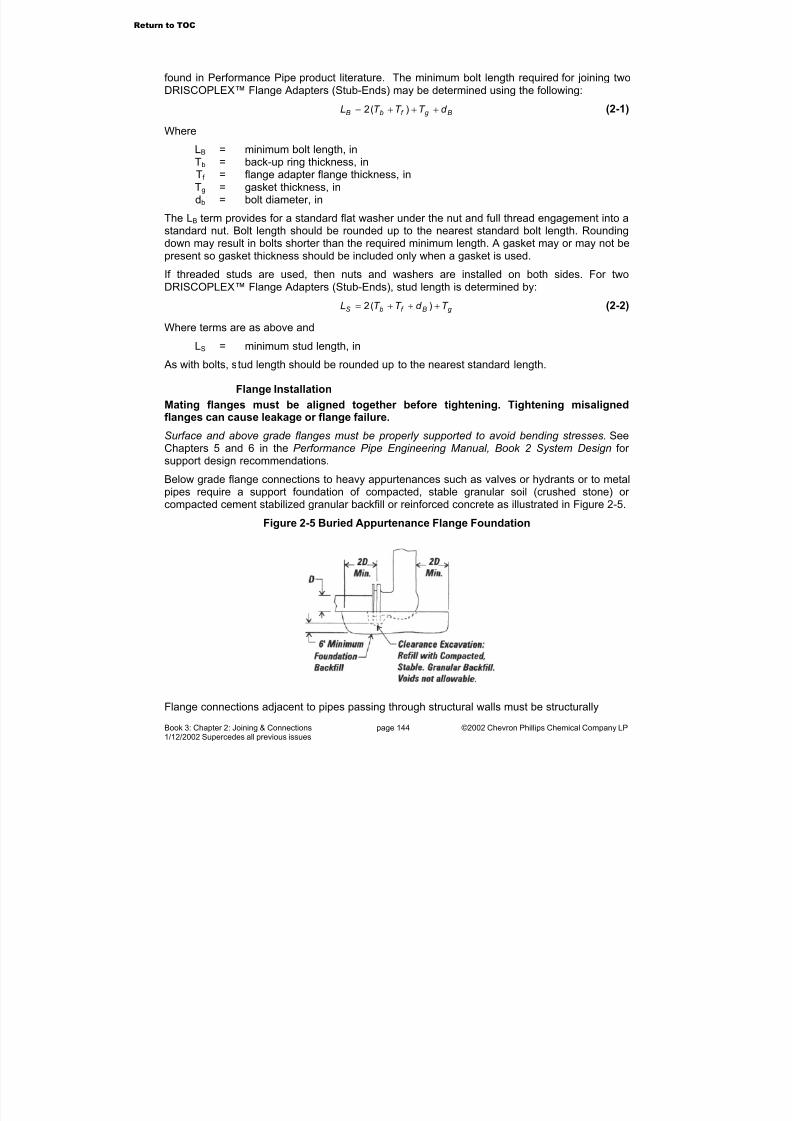
7/23/2019 The Performance Pipe Engineering Manual
http://slidepdf.com/reader/full/the-performance-pipe-engineering-manual 147/208
Book 3: Chapter 2: Joining & Connections page 144 ©2002 Chevron Phillips Chemical Company LP1/12/2002 Supercedes all previous issues
found in Performance Pipe product literature. The minimum bolt length required for joining twoDRISCOPLEX™ Flange Adapters (Stub-Ends) may be determined using the following:
Bg f bB d T T T L +++= )(2 (2-1)
Where
LB = minimum bolt length, inTb = back-up ring thickness, inTf = flange adapter flange thickness, inTg = gasket thickness, indb = bolt diameter, in
The LB term provides for a standard flat washer under the nut and full thread engagement into astandard nut. Bolt length should be rounded up to the nearest standard bolt length. Roundingdown may result in bolts shorter than the required minimum length. A gasket may or may not bepresent so gasket thickness should be included only when a gasket is used.
If threaded studs are used, then nuts and washers are installed on both sides. For twoDRISCOPLEX™ Flange Adapters (Stub-Ends), stud length is determined by:
g Bf bS T d T T L +++= )(2 (2-2)
Where terms are as above and
LS = minimum stud length, in
As with bolts, stud length should be rounded up to the nearest standard length.
Flange Installation
Mating flanges must be aligned together before tightening. Tightening misalignedflanges can cause leakage or flange failure.
Surface and above grade flanges must be properly supported to avoid bending stresses. SeeChapters 5 and 6 in the Performance Pipe Engineering Manual, Book 2 System Design for support design recommendations.
Below grade flange connections to heavy appurtenances such as valves or hydrants or to metalpipes require a support foundation of compacted, stable granular soil (crushed stone) or compacted cement stabilized granular backfill or reinforced concrete as illustrated in Figure 2-5.
Figure 2-5 Buried Appurtenance Flange Foundation
Flange connections adjacent to pipes passing through structural walls must be structurally
Return to TOC
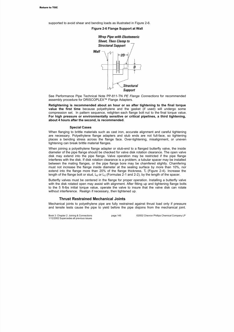
7/23/2019 The Performance Pipe Engineering Manual
http://slidepdf.com/reader/full/the-performance-pipe-engineering-manual 148/208
Book 3: Chapter 2: Joining & Connections page 145 ©2002 Chevron Phillips Chemical Company LP1/12/2002 Supercedes all previous issues
supported to avoid shear and bending loads as illustrated in Figure 2-6.
Figure 2-6 Flange Support at Wall
See Performance Pipe Technical Note PP-811-TN PE Flange Connections for recommendedassembly procedure for DRISCOPLEX™ Flange Adapters.
Retightening is recommended about an hour or so after tightening to the final torquevalue the first time because polyethylene and the gasket (if used) will undergo somecompression set. In pattern sequence, retighten each flange bolt nut to the final torque value.
For high pressure or environmentally sensitive or critical pipelines, a third tightening,about 4 hours after the second, is recommended.
Special Cases
When flanging to brittle materials such as cast iron, accurate alignment and careful tightening
are necessary. Polyethylene flange adapters and stub ends are not full-face, so tighteningplaces a bending stress across the flange face. Over-tightening, misalignment, or uneventightening can break brittle material flanges.
When joining a polyethylene flange adapter or stub-end to a flanged butterfly valve, the insidediameter of the pipe flange should be checked for valve disk rotation clearance. The open valvedisk may extend into the pipe flange. Valve operation may be restricted if the pipe flangeinterferes with the disk. If disk rotation clearance is a problem, a tubular spacer may be installedbetween the mating flanges, or the pipe flange bore may be chamfered slightly. Chamferingmust not increase the flange inside diameter at the sealing surface by more than 10%, nor extend into the flange more than 20% of the flange thickness, T f (Figure 2-4). Increase thelength of the flange bolt or stud, LB or LS (Formulas 2-1 and 2-2), by the length of the spacer.
Butterfly valves must be centered in the flange for proper operation. Installing a butterfly valvewith the disk rotated open may assist with alignment. After fitting up and tightening flange boltsto the 5 ft-lbs initial torque value, operate the valve to insure that the valve disk can rotatewithout interference. Realign if necessary, then tightened up.
Thrust Restrained Mechanical Joints
Mechanical joints to polyethylene pipe are fully restrained against thrust load only if pressureand tensile tests cause the pipe to yield before the pipe disjoins from the mechanical joint.
Return to TOC
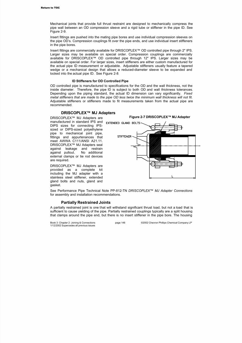
7/23/2019 The Performance Pipe Engineering Manual
http://slidepdf.com/reader/full/the-performance-pipe-engineering-manual 149/208
Book 3: Chapter 2: Joining & Connections page 146 ©2002 Chevron Phillips Chemical Company LP1/12/2002 Supercedes all previous issues
Mechanical joints that provide full thrust restraint are designed to mechanically compress thepipe wall between an OD compression sleeve and a rigid tube or stiffener in the pipe ID. SeeFigure 2-9.
Insert fittings are pushed into the mating pipe bores and use individual compression sleeves onthe pipe OD’s. Compression couplings fit over the pipe ends, and use individual insert stiffeners
in the pipe bores.Insert fittings are commercially available for DRISCOPLEX™ OD controlled pipe through 2" IPS.Larger sizes may be available on special order. Compression couplings are commerciallyavailable for DRISCOPLEX™ OD controlled pipe through 12" IPS. Larger sizes may beavailable on special order. For larger sizes, insert stiffeners are either custom manufactured for the actual pipe ID measurement or adjustable. Adjustable stiffeners usually feature a taperedwedge or a mechanical design that allows a reduced-diameter sleeve to be expanded andlocked into the actual pipe ID. See Figure 2-8.
ID Stiffeners for OD Controlled Pipe
OD controlled pipe is manufactured to specifications for the OD and the wall thickness, not theinside diameter. Therefore, the pipe ID is subject to both OD and wall thickness tolerances.
Depending upon the piping standard, the actual ID dimension can vary significantly. Fixed metal stiffeners that are made to the pipe OD less twice the minimum wall thickness will not fit. Adjustable stiffeners or stiffeners made to fit measurements taken from the actual pipe arerecommended.
DRISCOPLEX™ MJ Adapters
DRISCOPLEX™ MJ Adapters aremanufactured in standard IPS andDIPS sizes for connecting IPS-sized or DIPS-sized polyethylenepipe to mechanical joint pipe,fittings and appurtenances thatmeet AWWA C111/ANSI A21.11.DRISCOPLEX™ MJ Adapters sealagainst leakage and restrainagainst pullout. No additionalexternal clamps or tie rod devicesare required.
DRISCOPLEX™ MJ Adapters areprovided as a complete kitincluding the MJ adapter with astainless steel stiffener, extendedgland bolts and nuts, gland and
gasket.See Performance Pipe Technical Note PP-812-TN DRISCOPLEX™ MJ Adapter Connections for assembly and installation recommendations.
Partially Restrained Joints
A partially restrained joint is one that will withstand significant thrust load, but not a load that issufficient to cause yielding of the pipe. Partially restrained couplings typically are a split housingthat clamps around the pipe end, but there is no insert stiffener in the pipe bore. The housing
Figure 2-7 DRISCOPLEX™ MJ Adapter
Return to TOC
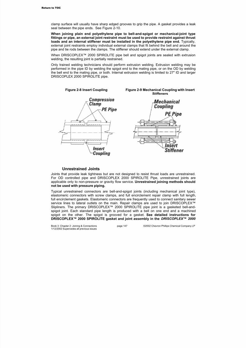
7/23/2019 The Performance Pipe Engineering Manual
http://slidepdf.com/reader/full/the-performance-pipe-engineering-manual 150/208
Book 3: Chapter 2: Joining & Connections page 147 ©2002 Chevron Phillips Chemical Company LP1/12/2002 Supercedes all previous issues
clamp surface will usually have sharp edged grooves to grip the pipe. A gasket provides a leakseal between the pipe ends. See Figure 2-10.
When joining plain end polyethylene pipe to bell-and-spigot or mechanical-joint typefittings or pipe, an external joint restraint must be used to provide restraint against thrustloads and an internal stiffener must be installed in the polyethylene pipe end.Typically,
external joint restraints employ individual external clamps that fit behind the bell and around thepipe and tie rods between the clamps. The stiffener should extend under the external clamp.
When DRISCOPLEX™ 2000 SPIROLITE pipe bell and spigot joints are sealed with extrusionwelding, the resulting joint is partially restrained.
Only trained welding technicians should perform extrusion welding. Extrusion welding may beperformed in the pipe ID by welding the spigot end to the mating pipe, or on the OD by weldingthe bell end to the mating pipe, or both. Internal extrusion welding is limited to 27" ID and larger DRISCOPLEX 2000 SPIROLITE pipe.
Figure 2-8 Insert Coupling Figure 2-9 Mechanical Coupling with Insert
Stiffeners
Unrestrained Joints
Joints that provide leak tightness but are not designed to resist thrust loads are unrestrained.For OD controlled pipe and DRISCOPLEX 2000 SPIROLITE Pipe, unrestrained joints areapplicable only to non-pressure or gravity flow service. Unrestrained joining methods shouldnot be used with pressure piping.
Typical unrestrained connectors are bell-and-spigot joints (including mechanical joint type),elastomeric connectors with screw clamps, and full encirclement repair clamp with full length,full encirclement gaskets. Elastomeric connectors are frequently used to connect sanitary sewer service lines to lateral outlets on the main. Repair clamps are used to join DRISCOPLEX™Slipliners. The primary DRISCOPLEX™ 2000 SPIROLITE pipe joint is a gasketed bell-and-spigot joint. Each standard pipe length is produced with a bell on one end and a machinedspigot on the other. The spigot is grooved for a gasket. See detailed instructions for DRISCOPLEX™ 2000 SPIROLITE gasket and joint assembly in the DRISCOPLEX™ 2000
Return to TOC

7/23/2019 The Performance Pipe Engineering Manual
http://slidepdf.com/reader/full/the-performance-pipe-engineering-manual 151/208
Book 3: Chapter 2: Joining & Connections page 148 ©2002 Chevron Phillips Chemical Company LP1/12/2002 Supercedes all previous issues
SPIROLITE Installation Guide.
Figure 2-10 Partially RestrainedCompression Coupling
Figure 2-11 External Joint Restraint
Special Joining ConsiderationsWhen transitions are made between fully restrained polyethylene pressure pipe and non-restrained non-polyethylene pressure pipes such as ductile iron or PVC, measures such aslongitudinal force thrust blocks (in-line anchoring) and external restraints applied to non-restrained joints are necessary. Polyethylene pipe when pressurized will expand in diameter and shorten in length according to the Poisson ratio of the material. While Poisson effect pipeshortening is minimal for short lengths, a long length of fully restrained PE pressure pipe canshorten enough to disjoin unrestrained non-PE transition joints connected to the PE pipe length.See Performance Pipe Technical Note PP-813 TN for additional information.
Other Joining Techniques
Pipe Threads
Standard 60° v-groove taper pipe threads are not recommended for joiningDRISCOPLEX™ OD controlled pipe or for joining components to OD controlled pipe.Threaded polyethylene pipe is easily stripped or cross-threaded, and the thread depth reduceswall thickness. Threaded holes in PE pipe are easily striped or cross-threaded.
Extrusion Welding
Extrusion welding employs a small handheld extruder that feeds molten PE onto pre-heated,specially prepared PE surfaces. Preparation requires removing a thin layer of material from thesurfaces of the parts being welded and cleaning, scraping, planing or beveling. The extrusiongun preheats the surfaces; then feeds a molten polyethylene bead into the prepared joint area.
The ideal environment for extrusion welding is in a plant or shop area where the requisiteconditions for good welding are present, that is, cleanliness, properly trained operators and thespecial jigs and tools that are required for the extrusion welding process. Using prescribedprocedures, welded joints produced under ideal conditions can be expected to develop up to
Return to TOC
7/23/2019 The Performance Pipe Engineering Manual
http://slidepdf.com/reader/full/the-performance-pipe-engineering-manual 152/208
Book 3: Chapter 2: Joining & Connections page 149 ©2002 Chevron Phillips Chemical Company LP1/12/2002 Supercedes all previous issues
70% the tensile strength of the base material. Field joints usually require special care and highlytrained operators to produce similar quality joints.
Typically, extrusion welding is used in the manufacture of structures for low pressure or non-pressure service, such as manholes, tanks, very large diameter pipe fittings, dual containmentsystems and odor control structures.
Extrusion welding is not a substitute for butt fusion or saddle fusion and should not beused to repair pressure pipe or fittings. Extrusion welding is not the same as Hot Gas(Hot Air) Welding.
Hot Gas Welding
Performance Pipe does not recommend hot gas (hot air) welding for joining PerformancePipe polyethylene piping products. Hot air (hot gas) welding uses hot air to melt apolyethylene “welding rod” and join the surfaces. It is usually limited to joining low molecular weight, high melt flow rate polyethylene materials because such materials are easy to melt andflow together. However, Performance Pipe polyethylene pipe products are made from stress-rated, high molecular weight, low melt flow rate polyethylene materials. These high qualitypolyethylene materials do not melt or flow easily. Hot gas weld strength is typically less than15% of the parent material’s strength, thus this joining method is unsuitable for joining stress-rated polyethylene materials.
Manhole ConnectionsMethods of connecting to DRISCOPLEX™ Standard Manholes and Standard Manhole Tees aredetailed in DRISCOPLEX™ DriscoPlex 2000 SPIROLITE product literature. Connections areby standard gasketed bell-and-spigot joints, a gasketed closure joint or flanges.
For precast concrete manholes, options include installing a DRISCOPLEX 2000 SPIROLITE “A-Connector” pipe into an A-Lok®1 gasket cast into the manhole base or by casting or fastening aKor-N-Seal®2 boot or equivalent to the manhole outlet wall and securing OD controlled pipe or DRISCOPLEX 2000 SPIROLITE Smooth OD Pipe in the boot. Options for connecting to
Poured-In-Place manhole bases include casting the DRISCOPLEX 2000 SPIROLITETomahawk™ connector pipe into the manhole base or casting the manhole base around ODcontrolled pipe or DRISCOPLEX 2000 SPIROLITE Pipe that has been coated with Noah’sPitch®3 and wrapped with Kent-Seal®4 or an equivalent tar-based mastic. After the manholebase concrete has set, benching concrete is placed and finished, and the top of the ODcontrolled pipe or DRISCOPLEX™ 2000 SPIROLITE Pipe is cut out.
Please refer to ASTM F 585 and Performance Pipe product literature for additional informationon sliplining and connecting to manholes.
Branch Connections
DRISCOPLEX™ OD Controlled Pressure PipingBranch connections may be made with equal outlet and reduced outlet tees that are installed in
1A-Lok® is a registered trademark of A-Lok Products, Inc.
2Kor-N-Seal® is a registered trademark of NPC Corporation.
3Noah’s Pitch is a registered trademark of Celotex Corporation.
4Kent Seal® is a registered trademark of the Hamilton Kent Corporation.
Return to TOC
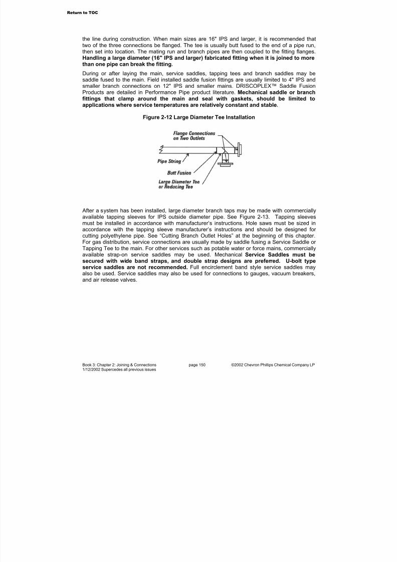
7/23/2019 The Performance Pipe Engineering Manual
http://slidepdf.com/reader/full/the-performance-pipe-engineering-manual 153/208
Book 3: Chapter 2: Joining & Connections page 150 ©2002 Chevron Phillips Chemical Company LP1/12/2002 Supercedes all previous issues
the line during construction. When main sizes are 16" IPS and larger, it is recommended thattwo of the three connections be flanged. The tee is usually butt fused to the end of a pipe run,then set into location. The mating run and branch pipes are then coupled to the fitting flanges.Handling a large diameter (16" IPS and larger) fabricated fitting when it is joined to morethan one pipe can break the fitting.
During or after laying the main, service saddles, tapping tees and branch saddles may besaddle fused to the main. Field installed saddle fusion fittings are usually limited to 4" IPS andsmaller branch connections on 12" IPS and smaller mains. DRISCOPLEX™ Saddle FusionProducts are detailed in Performance Pipe product literature. Mechanical saddle or branchfittings that clamp around the main and seal with gaskets, should be limited toapplications where service temperatures are relatively constant and stable.
Figure 2-12 Large Diameter Tee Installation
After a system has been installed, large diameter branch taps may be made with commerciallyavailable tapping sleeves for IPS outside diameter pipe. See Figure 2-13. Tapping sleevesmust be installed in accordance with manufacturer’s instructions. Hole saws must be sized in
accordance with the tapping sleeve manufacturer’s instructions and should be designed for cutting polyethylene pipe. See “Cutting Branch Outlet Holes” at the beginning of this chapter.For gas distribution, service connections are usually made by saddle fusing a Service Saddle or Tapping Tee to the main. For other services such as potable water or force mains, commerciallyavailable strap-on service saddles may be used. Mechanical Service Saddles must besecured with wide band straps, and double strap designs are preferred. U-bolt typeservice saddles are not recommended. Full encirclement band style service saddles mayalso be used. Service saddles may also be used for connections to gauges, vacuum breakers,and air release valves.
Return to TOC
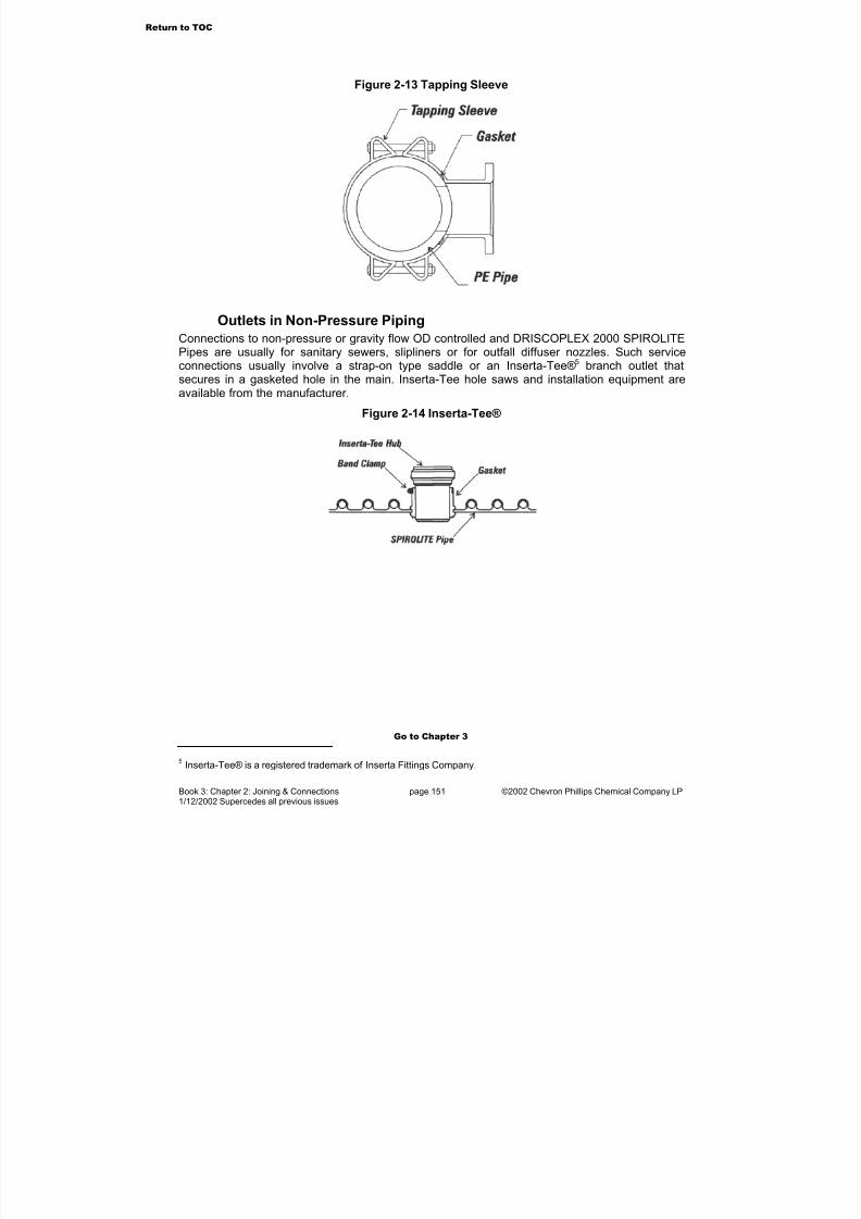
7/23/2019 The Performance Pipe Engineering Manual
http://slidepdf.com/reader/full/the-performance-pipe-engineering-manual 154/208
Book 3: Chapter 2: Joining & Connections page 151 ©2002 Chevron Phillips Chemical Company LP1/12/2002 Supercedes all previous issues
Figure 2-13 Tapping Sleeve
Outlets in Non-Pressure Piping
Connections to non-pressure or gravity flow OD controlled and DRISCOPLEX 2000 SPIROLITEPipes are usually for sanitary sewers, slipliners or for outfall diffuser nozzles. Such serviceconnections usually involve a strap-on type saddle or an Inserta-Tee®5 branch outlet thatsecures in a gasketed hole in the main. Inserta-Tee hole saws and installation equipment areavailable from the manufacturer.
Figure 2-14 Inserta-Tee®
5Inserta-Tee® is a registered trademark of Inserta Fittings Company.
Go to Chapter 3
Return to TOC
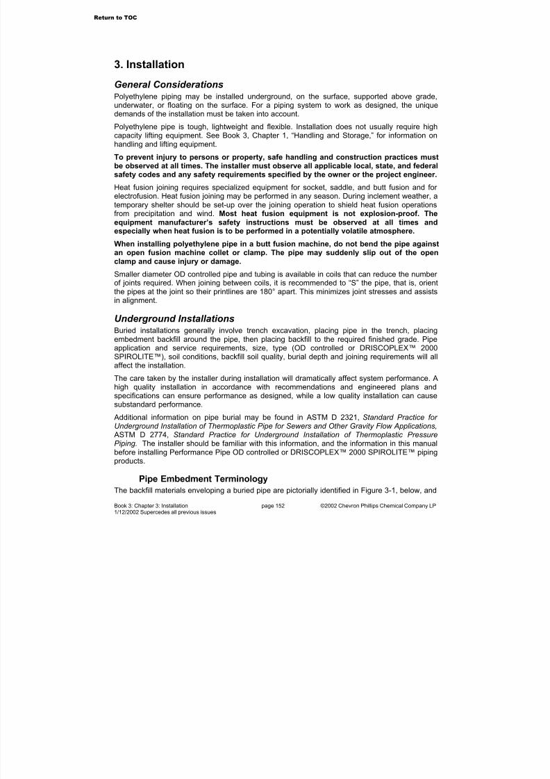
7/23/2019 The Performance Pipe Engineering Manual
http://slidepdf.com/reader/full/the-performance-pipe-engineering-manual 155/208
Book 3: Chapter 3: Installation page 152 ©2002 Chevron Phillips Chemical Company LP1/12/2002 Supercedes all previous issues
3. Installation
General ConsiderationsPolyethylene piping may be installed underground, on the surface, supported above grade,
underwater, or floating on the surface. For a piping system to work as designed, the uniquedemands of the installation must be taken into account.
Polyethylene pipe is tough, lightweight and flexible. Installation does not usually require highcapacity lifting equipment. See Book 3, Chapter 1, “Handling and Storage,” for information onhandling and lifting equipment.
To prevent injury to persons or property, safe handling and construction practices mustbe observed at all times. The installer must observe all applicable local, state, and federalsafety codes and any safety requirements specified by the owner or the project engineer.
Heat fusion joining requires specialized equipment for socket, saddle, and butt fusion and for electrofusion. Heat fusion joining may be performed in any season. During inclement weather, atemporary shelter should be set-up over the joining operation to shield heat fusion operationsfrom precipitation and wind. Most heat fusion equipment is not explosion-proof. Theequipment manufacturer’s safety instructions must be observed at all times andespecially when heat fusion is to be performed in a potentially volatile atmosphere.
When installing polyethylene pipe in a butt fusion machine, do not bend the pipe againstan open fusion machine collet or clamp. The pipe may suddenly slip out of the openclamp and cause injury or damage.
Smaller diameter OD controlled pipe and tubing is available in coils that can reduce the number of joints required. When joining between coils, it is recommended to “S” the pipe, that is, orientthe pipes at the joint so their printlines are 180° apart. This minimizes joint stresses and assistsin alignment.
Underground InstallationsBuried installations generally involve trench excavation, placing pipe in the trench, placingembedment backfill around the pipe, then placing backfill to the required finished grade. Pipeapplication and service requirements, size, type (OD controlled or DRISCOPLEX™ 2000SPIROLITE™), soil conditions, backfill soil quality, burial depth and joining requirements will allaffect the installation.
The care taken by the installer during installation will dramatically affect system performance. Ahigh quality installation in accordance with recommendations and engineered plans andspecifications can ensure performance as designed, while a low quality installation can causesubstandard performance.
Additional information on pipe burial may be found in ASTM D 2321, Standard Practice for Underground Installation of Thermoplastic Pipe for Sewers and Other Gravity Flow Applications, ASTM D 2774, Standard Practice for Underground Installation of Thermoplastic PressurePiping. The installer should be familiar with this information, and the information in this manualbefore installing Performance Pipe OD controlled or DRISCOPLEX™ 2000 SPIROLITE™ pipingproducts.
Pipe Embedment Terminology
The backfill materials enveloping a buried pipe are pictorially identified in Figure 3-1, below, and
Return to TOC
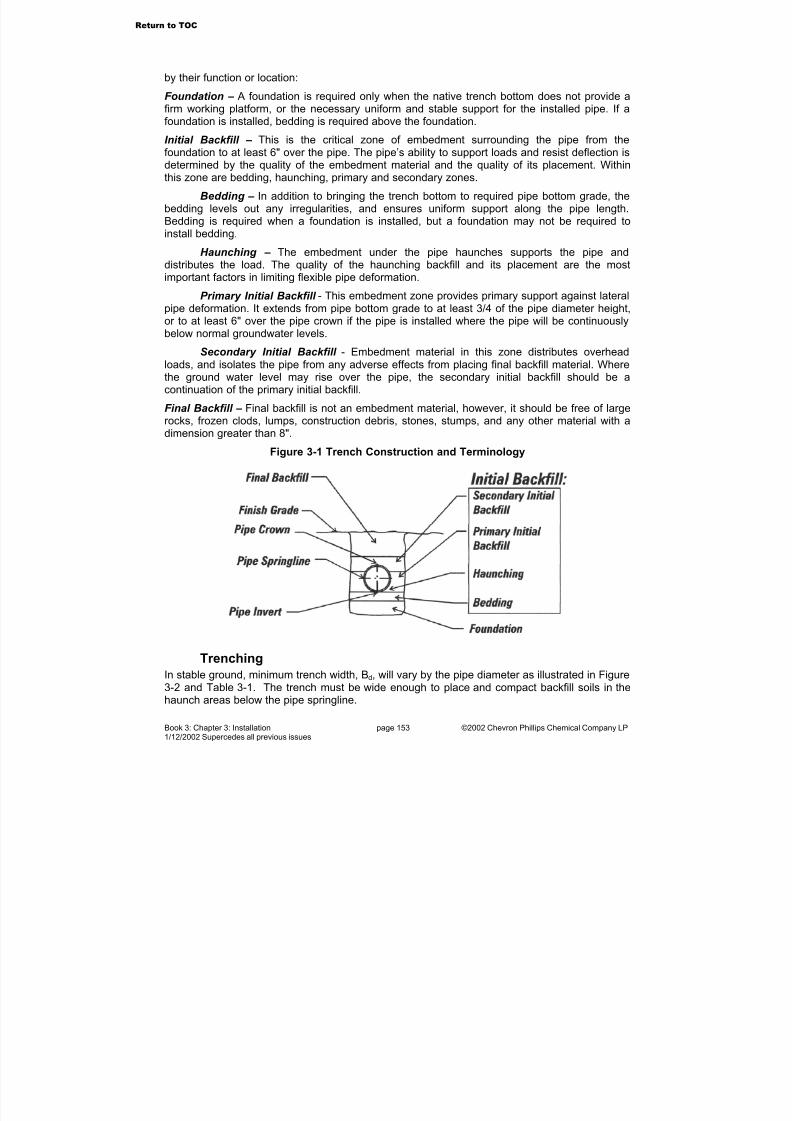
7/23/2019 The Performance Pipe Engineering Manual
http://slidepdf.com/reader/full/the-performance-pipe-engineering-manual 156/208
Book 3: Chapter 3: Installation page 153 ©2002 Chevron Phillips Chemical Company LP1/12/2002 Supercedes all previous issues
by their function or location:
Foundation – A foundation is required only when the native trench bottom does not provide afirm working platform, or the necessary uniform and stable support for the installed pipe. If afoundation is installed, bedding is required above the foundation.
Initial Backfill – This is the critical zone of embedment surrounding the pipe from the
foundation to at least 6" over the pipe. The pipe’s ability to support loads and resist deflection isdetermined by the quality of the embedment material and the quality of its placement. Withinthis zone are bedding, haunching, primary and secondary zones.
Bedding – In addition to bringing the trench bottom to required pipe bottom grade, thebedding levels out any irregularities, and ensures uniform support along the pipe length.Bedding is required when a foundation is installed, but a foundation may not be required toinstall bedding.
Haunching – The embedment under the pipe haunches supports the pipe anddistributes the load. The quality of the haunching backfill and its placement are the mostimportant factors in limiting flexible pipe deformation.
Primary Initial Backfill - This embedment zone provides primary support against lateralpipe deformation. It extends from pipe bottom grade to at least 3/4 of the pipe diameter height,or to at least 6" over the pipe crown if the pipe is installed where the pipe will be continuouslybelow normal groundwater levels.
Secondary Initial Backfill - Embedment material in this zone distributes overheadloads, and isolates the pipe from any adverse effects from placing final backfill material. Wherethe ground water level may rise over the pipe, the secondary initial backfill should be acontinuation of the primary initial backfill.
Final Backfill – Final backfill is not an embedment material, however, it should be free of largerocks, frozen clods, lumps, construction debris, stones, stumps, and any other material with adimension greater than 8".
Figure 3-1 Trench Construction and Terminology
Trenching
In stable ground, minimum trench width, Bd, will vary by the pipe diameter as illustrated in Figure3-2 and Table 3-1. The trench must be wide enough to place and compact backfill soils in thehaunch areas below the pipe springline.
Return to TOC

7/23/2019 The Performance Pipe Engineering Manual
http://slidepdf.com/reader/full/the-performance-pipe-engineering-manual 157/208
Book 3: Chapter 3: Installation page 154 ©2002 Chevron Phillips Chemical Company LP1/12/2002 Supercedes all previous issues
Figure 3-2 Trench Width Table 3-1 Minimum Trench Width
Nominal PipeOD, in
MinimumTrench Width,
Bd , in
Parallel PipeClearance, in
<3 12 4
3 – 16 Pipe OD + 12 6
18 – 34 Pipe OD + 18 9
36 – 63 Pipe OD + 24 12
72 - 96 Pipe OD + 36 18
To minimize the load on the pipe, the maximum trench width should not exceed the minimumtrench width by more than 18" plus the thickness of any sheeting, shoring or shielding, unlessapproved by the engineer. For trenches containing multiple pipes, the distance between parallelpipes should be the same as the clearance distance between the pipe and the trench wall. SeeTable 3-1.
Depending upon trench soil stability and depth, trench sides above the pipe crown may need tobe sloped or stepped as illustrated in Figure 3-2. When trenching in ground not considered tobe stable, the trench width above the pipe crown should be sloped and/or widened. Trenchsidewall bracing such as trench shield or sheeting should always be used wherever required bysite safety conditions, by OSHA, or by other regulatory agencies. When using a trench box, atrench offset should be excavated at a depth between the pipe crown and 1/4 pipe diameter below the pipe crown; then the trench box should be installed on the offset shelf. Further excavation of the pipe zone trench down to the foundation grade should be performed within theprotection of the trench box.
Figure 3-3 Trench Box Installation
For pressure piping systems such as water mains, gas mains, or sewage force mains, the grade
of the trench bottom is not critical. The trench bottom may undulate, but must support the pipecontinuously and be free from ridges, hollows, lumps and the like. Any significant irregularitiesmust be leveled off and/or filled with compacted embedment backfill. If the trench bottom isreasonably uniform, and the soil is stable and free of rock, foundation or bedding may not berequired.
For gravity drainage systems of Performance Pipe OD controlled or DRISCOPLEX™ 2000SPIROLITE™ pipe, the trench bottom determines the pipe grade, so the trench bottom must beconstructed to the required grade, usually by installing foundation and bedding, or bedding. If
Return to TOC

7/23/2019 The Performance Pipe Engineering Manual
http://slidepdf.com/reader/full/the-performance-pipe-engineering-manual 158/208
Book 3: Chapter 3: Installation page 155 ©2002 Chevron Phillips Chemical Company LP1/12/2002 Supercedes all previous issues
the trench bottom is reasonably uniform and the soil is stable and free of rock, foundation or bedding may not be required.
The pipe should be laid on a stable foundation. Where water is present in the trench, or wherethe trench bottom is unstable, excess water should be removed before laying the pipe. Groundwater should be lowered to below the level of the bedding material. During dewatering, take
care not to remove sand or silt, and not to displace foundation or bedding soil material.Where an unstable trench bottom exists such as in mucky or sandy soils with poor bearingstrength, trench bottom stabilization is required by excavating the trench below the pipe bottomgrade, and installing a foundation and bedding, or a bedding of compacted Class I or Class IImaterials to the pipe bottom grade. When required, the minimum foundation thickness is 6".When bedding and foundation are both required, the minimum bedding thickness is 4". Withouta foundation, the minimum bedding thickness is 6". All materials used for bedding, haunching,primary and secondary backfill should be installed to at least 90% Standard Proctor Density, or as specified by the engineer. Mechanical compaction, which may be as simple as shovel slicingClass I material, is usually required to achieve 90% Standard Proctor Density.
When the pipe is laid in a rock cut or stony soil, the trench should be excavated at least 6"below pipe bottom grade, and brought back to grade with compacted bedding. Remove ledgerock, boulders, and large stones to avoid point contacts, and to provide a uniform bed for thepipe.
The approximate length of open trench required to lay long strings of OD controlled pipe may bedetermined from Formula 3-1:
)(610075.1 H DH L −+= (3-1)
Where
L = trench length, ftH = trench depth, ftD = pipe diameter, in
Placing Pipe in the Trench
OD controlled pipe up to about 8" diameter and weighing roughly 6 lbs per foot or less canusually be placed in the trench manually. Heavier, larger diameter OD controlled pipe, and allDRISCOPLEX™ 2000 SPIROLITE™ pipe will require appropriate handling equipment to lift,move, and lower the pipe into the trench. Pipe must not be dumped, dropped, pushed, or rolled into the trench. Appropriate safety precautions must be observed whenever persons are in or near the trench.
Requirements for handling and lifting equipment are discussed in “Handling and Storage” inBook 3, Chapter 1.
Cold (Field) BendingCoiled lengths and long strings of OD controlled pipe may be cold bent in the field. Allowablebend radius is determined by the pipe diameter and dimension ratio. See Table 3-3. When afitting or a flange connection is present in the bend, the allowable field bending radius iscontrolled by the rigidity of the fitting or flange connection.
Field bending usually involves excavating the trench to the desired bend radius, then sweepingor pulling the pipe string into the required bend and placing it in the trench. Temporary restraintsmay be required to bend the pipe, and to maintain the bend while placing the pipe in the trench
Return to TOC
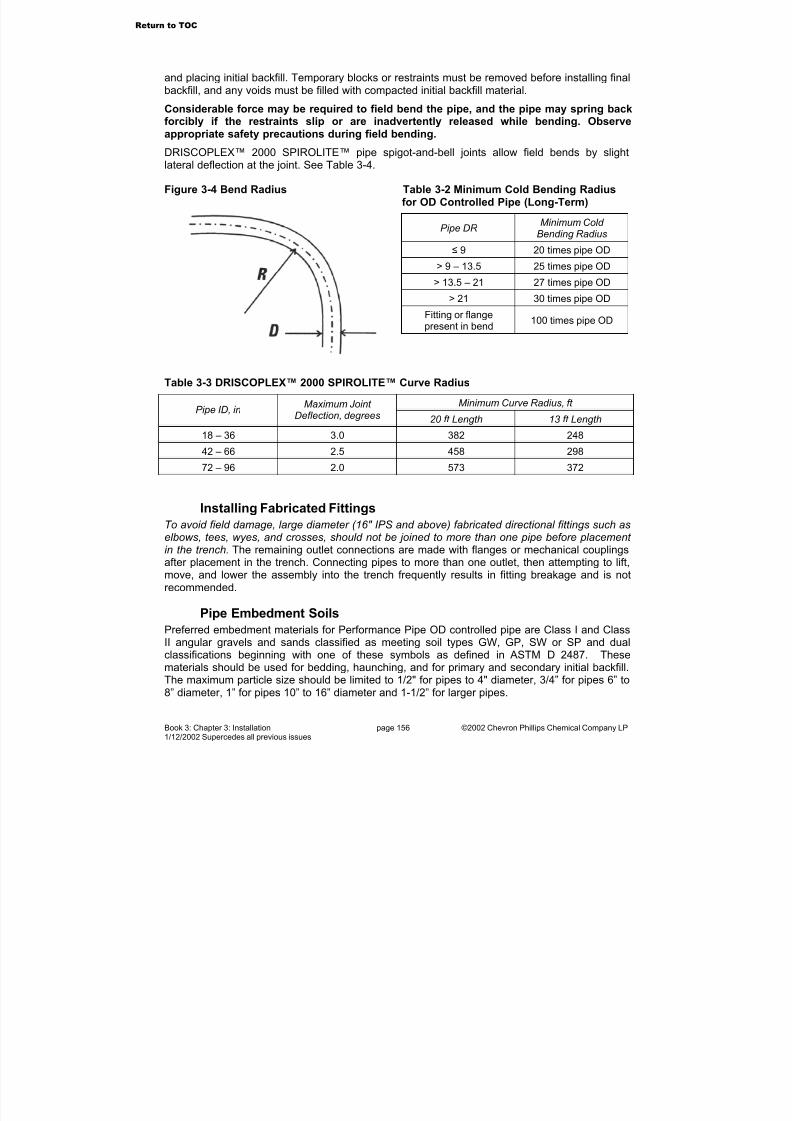
7/23/2019 The Performance Pipe Engineering Manual
http://slidepdf.com/reader/full/the-performance-pipe-engineering-manual 159/208
Book 3: Chapter 3: Installation page 156 ©2002 Chevron Phillips Chemical Company LP1/12/2002 Supercedes all previous issues
and placing initial backfill. Temporary blocks or restraints must be removed before installing finalbackfill, and any voids must be filled with compacted initial backfill material.
Considerable force may be required to field bend the pipe, and the pipe may spring backforcibly if the restraints slip or are inadvertently released while bending. Observeappropriate safety precautions during field bending.
DRISCOPLEX™ 2000 SPIROLITE™ pipe spigot-and-bell joints allow field bends by slightlateral deflection at the joint. See Table 3-4.
Figure 3-4 Bend Radius Table 3-2 Minimum Cold Bending Radiusfor OD Controlled Pipe (Long-Term)
Pipe DR Minimum Cold
Bending Radius
≤ 9 20 times pipe OD
> 9 – 13.5 25 times pipe OD
> 13.5 – 21 27 times pipe OD
> 21 30 times pipe ODFitting or flangepresent in bend
100 times pipe OD
Table 3-3 DRISCOPLEX™ 2000 SPIROLITE™ Curve Radius
Minimum Curve Radius, ft Pipe ID, in
Maximum Joint Deflection, degrees 20 ft Length 13 ft Length
18 – 36 3.0 382 248
42 – 66 2.5 458 29872 – 96 2.0 573 372
Installing Fabricated Fittings
To avoid field damage, large diameter (16" IPS and above) fabricated directional fittings such aselbows, tees, wyes, and crosses, should not be joined to more than one pipe before placement in the trench. The remaining outlet connections are made with flanges or mechanical couplingsafter placement in the trench. Connecting pipes to more than one outlet, then attempting to lift,move, and lower the assembly into the trench frequently results in fitting breakage and is notrecommended.
Pipe Embedment Soils
Preferred embedment materials for Performance Pipe OD controlled pipe are Class I and ClassII angular gravels and sands classified as meeting soil types GW, GP, SW or SP and dualclassifications beginning with one of these symbols as defined in ASTM D 2487. Thesematerials should be used for bedding, haunching, and for primary and secondary initial backfill.The maximum particle size should be limited to 1/2" for pipes to 4" diameter, 3/4” for pipes 6” to8” diameter, 1” for pipes 10” to 16” diameter and 1-1/2” for larger pipes.
Return to TOC
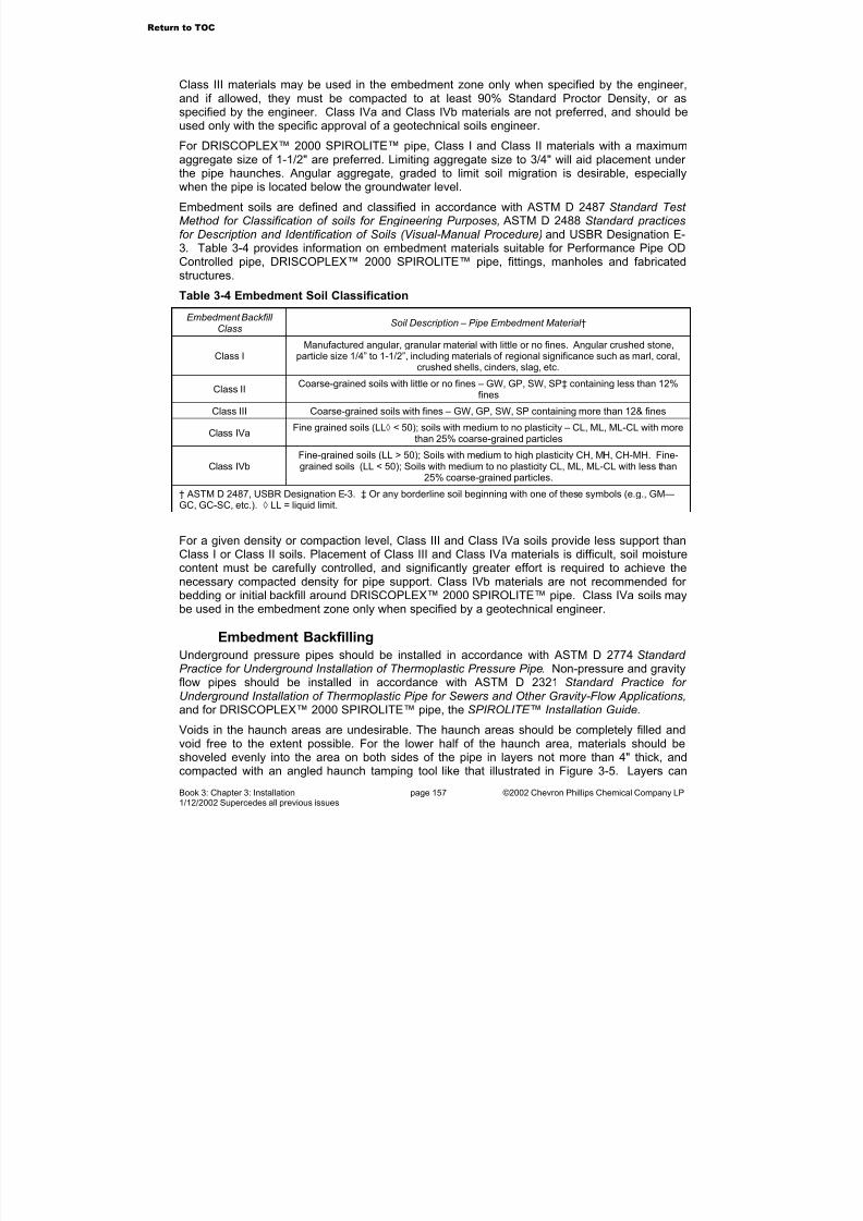
7/23/2019 The Performance Pipe Engineering Manual
http://slidepdf.com/reader/full/the-performance-pipe-engineering-manual 160/208
Book 3: Chapter 3: Installation page 157 ©2002 Chevron Phillips Chemical Company LP1/12/2002 Supercedes all previous issues
Class III materials may be used in the embedment zone only when specified by the engineer,and if allowed, they must be compacted to at least 90% Standard Proctor Density, or asspecified by the engineer. Class IVa and Class IVb materials are not preferred, and should beused only with the specific approval of a geotechnical soils engineer.
For DRISCOPLEX™ 2000 SPIROLITE™ pipe, Class I and Class II materials with a maximum
aggregate size of 1-1/2" are preferred. Limiting aggregate size to 3/4" will aid placement under the pipe haunches. Angular aggregate, graded to limit soil migration is desirable, especiallywhen the pipe is located below the groundwater level.
Embedment soils are defined and classified in accordance with ASTM D 2487 Standard Test Method for Classification of soils for Engineering Purposes, ASTM D 2488 Standard practicesfor Description and Identification of Soils (Visual-Manual Procedure) and USBR Designation E-3. Table 3-4 provides information on embedment materials suitable for Performance Pipe ODControlled pipe, DRISCOPLEX™ 2000 SPIROLITE™ pipe, fittings, manholes and fabricatedstructures.
Table 3-4 Embedment Soil Classification
Embedment Backfill
ClassSoil Description – Pipe Embedment Material †
Class IManufactured angular, granular material with little or no fines. Angular crushed stone,
particle size 1/4” to 1-1/2”, including materials of regional significance such as marl, coral,crushed shells, cinders, slag, etc.
Class IICoarse-grained soils with little or no fines – GW, GP, SW, SP‡ containing less than 12%
fines
Class III Coarse-grained soils with fines – GW, GP, SW, SP containing more than 12& fines
Class IVaFine grained soils (LL◊ < 50); soils with medium to no plasticity – CL, ML, ML-CL with more
than 25% coarse-grained particles
Class IVbFine-grained soils (LL > 50); Soils with medium to high plasticity CH, MH, CH-MH. Fine-grained soils (LL < 50); Soils with medium to no plasticity CL, ML, ML-CL with less than
25% coarse-grained particles.
† ASTM D 2487, USBR Designation E-3. ‡ Or any borderline soil beginning with one of these symbols (e.g., GM—GC, GC-SC, etc.). ◊ LL = liquid limit.
For a given density or compaction level, Class III and Class IVa soils provide less support thanClass I or Class II soils. Placement of Class III and Class IVa materials is difficult, soil moisturecontent must be carefully controlled, and significantly greater effort is required to achieve thenecessary compacted density for pipe support. Class IVb materials are not recommended for bedding or initial backfill around DRISCOPLEX™ 2000 SPIROLITE™ pipe. Class IVa soils maybe used in the embedment zone only when specified by a geotechnical engineer.
Embedment Backfilling
Underground pressure pipes should be installed in accordance with ASTM D 2774 Standard Practice for Underground Installation of Thermoplastic Pressure Pipe. Non-pressure and gravityflow pipes should be installed in accordance with ASTM D 2321 Standard Practice for Underground Installation of Thermoplastic Pipe for Sewers and Other Gravity-Flow Applications,and for DRISCOPLEX™ 2000 SPIROLITE™ pipe, the SPIROLITE™ Installation Guide.
Voids in the haunch areas are undesirable. The haunch areas should be completely filled andvoid free to the extent possible. For the lower half of the haunch area, materials should beshoveled evenly into the area on both sides of the pipe in layers not more than 4" thick, andcompacted with an angled haunch tamping tool like that illustrated in Figure 3-5. Layers can
Return to TOC

7/23/2019 The Performance Pipe Engineering Manual
http://slidepdf.com/reader/full/the-performance-pipe-engineering-manual 161/208
Book 3: Chapter 3: Installation page 158 ©2002 Chevron Phillips Chemical Company LP1/12/2002 Supercedes all previous issues
then be increased to 6" and flat tamping tools can be used.
Figure 3-5 Haunch Tamping Tool
Following haunching, primary and secondary initial backfill materials should be placed in 6"layers and compacted with flat tamping tools. If mechanical tampers are used, take care not todamage the pipe. If sheeting has been used, the sheeting should be lifted progressively for eachlayer.
Joint Anchoring with Thrust Blocks
DRISCOPLEX™ pressure pipe systems must be assembled with fully restrained joints, or withpartially restrained joints AND external joint restraints. DRISCOPLEX™ OD controlled pressurepiping systems that are joined by heat fusion or flanges are fully restrained, and do not requireexternal joint restraints or thrust block joint anchors.
Partially restrained joints with joint restraints should be anchored with thrust blocks at fittings.However, thrust block anchoring is not a substitute for and must not be used in place of external joint restraints. Unrestrained connections are not recommended for use with DRISCOPLEX™pressure piping systems.
If used, thrust block anchors should be installed at direction changes and at dead ends. Thrust
block anchors should bear against undisturbed trench wall soil or well compacted backfill. Allowable horizontal bearing loads for concrete against undisturbed soil firm enough to betrenched without sheeting are 3000 to 6000 lb/ft2 depending upon soil rigidity. Thrust blockanchors should be located so they will not prevent access to joints.
Thrust blocks at polyethylene fittings must fully encapsulate the fitting to distribute stresses over the body of the fitting. Thrust blocks that do not fully encapsulate will bear on a small part of thefitting resulting in impingement loads that can cause premature failure. (Concrete encasementcannot be used to increase the pressure rating of a fabricated fitting.)
Anchor thrust reaction load from internal pressure or surge pressure may be determined by:
f i
i P F D
P T
4
2π
= (3-2)
Where
TP = internal pressure reaction thrust, lbPi = internal pressure, lb.in2 Di = pipe inside diameter, inFf = fitting factor, Table 3-5
See “Fluid Flow, Water Hammer and Pressure Surge Considerations” in Book 2, Chapter 4 for
Return to TOC

7/23/2019 The Performance Pipe Engineering Manual
http://slidepdf.com/reader/full/the-performance-pipe-engineering-manual 162/208
Book 3: Chapter 3: Installation page 159 ©2002 Chevron Phillips Chemical Company LP1/12/2002 Supercedes all previous issues
information on surge pressure in Performance Pipe pressure piping systems.
Table 3-5 Fitting Factor
Fitting Fitting Factor
90° ell 1.41
Caps, plugs, tees 1.00
45° ell 0.77
22-1/2°ell 0.39
11-1/4° ell 0.20
Centrifugal thrust due to water flowing in the pipe will also act against the thrust block.Centrifugal thrust load may be determined from:
Θ
=
2sin
288
22
g
V DT i
C
π ω (3-3)
Where terms are previously defined and
TC = centrifugal thrust, lb
ω = fluid density, lb/ft3 V = fluid velocity, ft/secg = acceleration of gravity, 32.2 ft/sec2 Θ = direction change angle, degrees
Controlling Shear and Bending Loads at Rigid Structures
Performance Pipe OD controlled or DRISCOPLEX™ 2000 SPIROLITE™ pipes that enter or exita casing or a structure wall such as a building wall, vault, or manhole, must be protected againstshear and bending loads that can develop from settlement and embedment consolidation.
Figure 3-6 Controlling Shear and Bending Figure 3-7 Flange Support at Wall
A compacted foundation and compacted bedding should be installed below the pipe where it
Return to TOC

7/23/2019 The Performance Pipe Engineering Manual
http://slidepdf.com/reader/full/the-performance-pipe-engineering-manual 163/208
Book 3: Chapter 3: Installation page 160 ©2002 Chevron Phillips Chemical Company LP1/12/2002 Supercedes all previous issues
exits the casing or structure as illustrated in Figure 3-6. At a casing entry or exit, the pipeshould be wrapped with an elastomeric sheet material; then the annulus between the pipe andthe casing should be sealed either mechanically or with a cement grout. The seal preventsbackfill migration into the annulus.
Where OD controlled pipe is flanged at a wall such as a building or vault wall, a structural
support as illustrated in Figure 3-7 is recommended to prevent shear and bending loads. Withinthe clamp, the pipe is protected against chafing by wrapping it with an elastomeric sheet.
Where Performance Pipe OD controlled pipe or fittings are joined to valves, hydrants, other heavy devices, or rigid pipes, a support pad as illustrated in Figure 3-8 should be providedbelow the device or rigid pipe, and for at least two pipe diameters length under the connectingpipes. Support pad materials should be at least compacted Class I or II soil, or cementstabilized Class I, II, or III soils, or poured concrete. Embedment soils around the connectingpipes, the device, and in any bell holes must be compacted.
Figure 3-8 Appurtenance Support Pad
Locating Tapes or WiresPolyethylene pipes are non-metallic, so once buried, metal detector type locators are ineffective.To facilitate locating buried pipe, metallic locating tapes or 12-14 AWG copper wire can beplaced in the trench. Locating tapes or wires are usually placed above the pipe between theinitial and final backfill.
Final Backfilling
In general, final backfill may be material excavated from the trench provided it is free of unsuitable matter such as lumps, stones, frozen clods, construction debris, boulders, and other materials exceeding 8" in their longest dimension.
Where the trench is subject to surcharge loads such as H-20 or E-80 live loads, or buildingfoundations or footings, or paved parking or storage areas, final backfill should be an angular Class I or Class II granular material, compacted to at least 95% Standard Proctor density or asspecified by the engineer.
Backfill Stabilizing Agents
In some regions, soil may be stabilized by the addition of a pebble lime and starch-basepolymer mixture. This mixture reacts with soil moisture and can generate temperatures inexcess of 200° F. Polyethylene pipe coming into direct contact with the reacting mixture can be
Return to TOC

7/23/2019 The Performance Pipe Engineering Manual
http://slidepdf.com/reader/full/the-performance-pipe-engineering-manual 164/208
Book 3: Chapter 3: Installation page 161 ©2002 Chevron Phillips Chemical Company LP1/12/2002 Supercedes all previous issues
weakened or damaged.
Therefore, un-reacted stabilizer and un-reacted stabilized soil must not come into contact withpolyethylene pipe. Mixing soil and stabilizing agents as the soil is excavated from the trench willusually allow sufficient time for reaction and cooling. After mixing, the stabilized soil must beallowed to react and cool completely before placing it around polyethylene pipe.
Burrowing Animal Control
Polyethylene contains nothing to attract burrowing rodents or insects, however burrowinganimals may find it easy to dig in trench backfill soils and may occasionally damage 4" andsmaller polyethylene pipes in their path. Larger pipes are too great an obstruction, and aregenerally free from such attacks.
The possibility of burrowing animal damage may be reduced a) by using commercially availablerepellent sprays in the ditch, b) by installing smaller lines below the animal’s normal activityarea, typically deeper than 3 feet, c) using larger diameter pipes, d) installing embedment zonebackfill that is difficult for the animals to penetrate such as angular crushed stone, or e) installingthe pipe or tubing within a shielding tube such as DRISCOPLEX™ 6600 Rodent ProtectionTubing.
Special Installation Techniques
Because of its flexibility and the high integrity of properly made butt fusion joints, specialinstallation techniques may be employed to install DRISCOPLEX™ OD controlled pipe. Specialtechniques include plowing, planting or pulling pipe into a narrow trench, horizontal boring, anddirectional boring. These techniques minimize excavation by making a tight fitting trench cut or hole for the pipe, and either pulling or placing the pipe in the cut. They require suitable nativesoil conditions that are free of large rocks, and except directional boring, are generally limited toshallower depths.
Plowing and Planting
Plowing and planting involve cutting a narrow trench, and feeding the pipe into the trenchthrough a shoe or chute fitted just behind the trench cutting equipment. Trench cuts for pipesaround 1-1/2" IPS and smaller are frequently made with vibratory plows. Larger sizes use wheelor chain type trenchers with semi-circular cutters. The trench width should be only slightly larger than the pipe outside diameter.
The shoe or chute should feed the pipe into the bottom of the cut. The short-term pipe bendingradius through the shoe may be tighter than the long-term cold bending radius in Table 3-2, butit must not be so tight that the pipe kinks. Table 3-6 presents minimum short-term bending radiifor applications such as plowing and planting. The pipe’s path through the shoe or chute shouldbe as friction free as practicable.
Table 3-6 Minimum short-Term Bending Radius
Pipe Dimension RatioMinimum short-Term
Bending Radius
≤ 9 10 times pipe OD
> 9 – 13.5 13 times pipe OD
> 13.5 – 21 17 times pipe OD
> 21 20 times pipe OD
Return to TOC

7/23/2019 The Performance Pipe Engineering Manual
http://slidepdf.com/reader/full/the-performance-pipe-engineering-manual 165/208
Book 3: Chapter 3: Installation page 162 ©2002 Chevron Phillips Chemical Company LP1/12/2002 Supercedes all previous issues
Pipe is usually fed over the trenching equipment and through the shoe or chute from coils or straight lengths that have been butt fused into a long string. Pipe up to 12" IPS has beeninstalled using this method.
Pulling-in
Pulling-in involves cutting a trench, then pulling the pipe in from one end of the trench. Pulling-in
may be accomplished as a simultaneous operation by attaching the leading end of the pipebehind the trench cutter, or as a separate operation after the trench has been opened. In either case, pulling-in requires a relatively straight trench and the pulling force applied to the pipe mustnot exceed the allowable tensile load, ATL, (safe pull strength) for the pipe. Therefore, thismethod is limited to shorter runs.
Allowable Tensile Load (safe pull strength) may be determined by:
−=
2
2 11
R R T f f D ATL Y T Y π (3-4)
Where
ATL = allowable tensile load, lbD = pipe outside diameter, inf Y = tensile yield design (safety) factor, Table 3-7f T = time under tension design (safety) factor, Table 3-7TY = pipe tensile yield strength, lb/in2 (Table 3-8)R = pipe dimension ratio (DR or SDR)
When polyethylene pipe is subjected to a significant short term pulling stress, the pipe willstretch somewhat before yielding. However, if the pulling stress is limited to about 40% of theyield strength, the pipe will usually recover undamaged to its original length in a day or less after the stress is removed.
Table 3-7 Recommended Design Factors
Factor Parameter Recommended Value
f Y Tensile yield design factor† 0.40
f T Time under tension design factor 1.0 for up to 1 h 0.95 for up to 12 h 0.91 for up to 24 h
† Design and safety factors are the inverse of each other. Multiplying by a 0.40 design factor is the same as dividingby a 2.5 safety factor.
Pipe yield strengths may be estimated by using the values from Table 3-8. Unlike more brittlematerials, polyethylene pipe materials stretch greatly between tensile yield and tensile break.Tensile yield to break elongations of 800% for HDPE and 1000% for MDPE are common.Further, tensile yield and break stresses are usually a similar value, so if pulling continues after the material has yielded, it will stretch to the breaking point with little change in pulling force.
Table 3-8 Approximate Tensile Yield Strength Values
Approximate Tensile Yield Strength, T Y , at Pipe TemperatureMaterial
73°F (23°C) 100°F (38°C) 120°F (49°C) 140°F (60°C)
MDPE 2600 lb/in2
(17.9 MPa) 2365 lb/in2
(16.3 MPa) 1920 lb/in2(15.4 MPa) 1640 lb/in
2(11.0 MPa)
HDPE 3200 lb/in2
(22.1 MPa) 2910 lb/in2
(17.4 MPa) 2365 lb/in2
(13.7 MPa) 2015 lb/in2
(14.3 MPa)
Return to TOC

7/23/2019 The Performance Pipe Engineering Manual
http://slidepdf.com/reader/full/the-performance-pipe-engineering-manual 166/208
Book 3: Chapter 3: Installation page 163 ©2002 Chevron Phillips Chemical Company LP1/12/2002 Supercedes all previous issues
When pulling polyethylene pipe, it is important to stay well below the yield strength, because theyield strength and the breaking strength are about the same, but in between the pipe can stretchover 400% before it breaks. Because yield and break strengths are about the same, pull forcegauges will not show that the pipe has been damaged. The only indication will be that thetrailing end stops while the pulling end continues to move.
When pulling-in polyethylene pipe, especially smaller diameters, the pulling force should bemonitored and kept below the safe pull strength for the pipe size, and both the pulling end andtrailing end should be monitored for continuous, smooth movement. A weak-link device shouldalways be installed at the lead end of the polyethylene pipe.
Because pull-in loads will cause the pipe to stretch, the leading end should be pulled past thetermination point by 4-5% of the total pulled-in length, and the trailing end should be left long bythe same amount. Final tie-ins should be made a day after the pull to allow the pipe to recover from the pulling stress and contract to its original pre-pull length. The extra length at both endsassures that the pipe won’t recede back past the tie-in points as it recovers from the pull.
Horizontal Boring
Horizontal boring or road boring is usually performed to install a pipeline below existing
roadways or structures where opening a trench may be impractical or undesirable. Typically,entry and exit pit excavations are required. Tunneling directly across and under the structuremakes the bore.
Road bores are usually performed using a rotating auger within a steel casing. The auger projects just ahead of the casing, and the auger and casing are advanced together across to theexit pit. If a casing is being installed, either the auger casing is left, or a new casing is installedby pulling it in from the exit pit while withdrawing the bore casing.
DRISCOPLEX™ OD controlled pipe may be installed through a casing, or directly in theborehole. For information on sealing the end of the casing, see “Controlling Shear and BendingLoads at Rigid Structures” earlier in this chapter.
When installed in a casing, OD controlled polyethylene pipe does not require centering spacers(centralizers) for electrical isolation to a metal casing. Polyethylene is non-conductive and willnot affect casing cathodic protection. Unless groundwater pressure could cause OD controlledpipe to collapse, grouting the casing annulus is not required.
Allowing the pipe to snake inside the casing can usually accommodate minor thermal lengthchanges of the polyethylene pipe in the casing. If used, centering spacers will force thermalexpansion thrust loads to the pipe ends, which may weaken or break casing end seals.
When installing OD controlled pipe either directly in the borehole or in a casing, joining to theinstalled pipe should be considered. Generally, the trailing end may be joined to the system byany appropriate method. However, the leading end may need to be a restrained mechanical joint, or electrofusion. If a casing is large enough to allow a flange adapter to pass, a split back-up ring as illustrated in Figure 3-9 may be used for the flange joint.
When installing smaller diameter pipes directly in a borehole, soil friction around the pipe mayresult in significant pulling forces. The allowable tensile load, Formula 3-4, for the pipe must notbe exceeded.
Return to TOC

7/23/2019 The Performance Pipe Engineering Manual
http://slidepdf.com/reader/full/the-performance-pipe-engineering-manual 167/208
Book 3: Chapter 3: Installation page 164 ©2002 Chevron Phillips Chemical Company LP1/12/2002 Supercedes all previous issues
Figure 3-9 Split Back-Up Ring
Horizontal Directional Drilling (HDD)
Horizontal directional drilling uses directional drilling techniques to guide a drill string along aborepath around obstacles such as under rivers or lakes or through congested undergroundinfrastructure. As with horizontal boring, horizontal directional drilling may be used to install acasing, or to directly install long strings of OD controlled pipe. DRISCOPLEX™ 2000SPIROLITE™ pipe with the standard gasketed spigot and bell joint is not recommended for HDD pull-in type installations.
As the hole is bored, a steel drill string is extended behind a cutting head. Drilling mud is usedto cool the cutter, flush excavated soil from the borehole and lubricate the borehole. At the endof the borepath, the drill string is angled upwards and through the surface. The cutting head isremoved and a backreamer attached. The pipe string is attached to the backreamer through aweak-link device. As the drill string is withdrawn to the drilling rig, the backreamer enlarges theborehole and the pipe string is drawn in. As with any pipe pulling technique, the movement of the pipe string and the pulling load on the polyethylene pipe (Formula 3-4) must be monitored.
Information on horizontal directional drilling is available in ASTM F 1962 and Performance PipeTechnical Note PP 800-TN.
Pipeline Rehabilitation Techniques
Existing underground pipelines may be rehabilitated with Performance Pipe OD controlled or DRISCOPLEX™ 2000 SPIROLITE™ pipe. Rehabilitation techniques include conventionalsliplining or insertion, and techniques to install a tight-fitting liner. Performance Pipe ODcontrolled pipe may be used for pressure or gravity flow service and gasketed spigot and bell joined DRISCOPLEX™ 2000 SPIROLITE™ pipe for gravity flow service.
Conventional Sliplining (Insertion Renewal) With OD Controlled Pipe
Conventional sliplining or insertion renewal is a pipeline rehabilitation technique where a new,smaller diameter pipe is installed within a larger existing pipe. “Sliplining” usually denotes sewer rehabilitation, and “Insertion Renewal” the rehabilitation of a pressure pipe line. Sliplining or insertion renewal reduces the bore of the rehabilitated pipeline, however, polyethylene pipeusually has lesser flow resistance compared to many conventional pipes and pressure ratingmay be improved, so the reduced bore may not significantly reduce flow capacity. In somecases, capacity may be unchanged, or even increased. See Table 4-10 in Book 2, Chapter 4,for comparative flows for slipliners.
Return to TOC
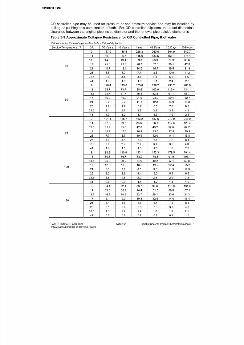
7/23/2019 The Performance Pipe Engineering Manual
http://slidepdf.com/reader/full/the-performance-pipe-engineering-manual 168/208
Book 3: Chapter 3: Installation page 165 ©2002 Chevron Phillips Chemical Company LP1/12/2002 Supercedes all previous issues
OD controlled pipe may be used for pressure or non-pressure service and may be installed bypulling or pushing or a combination of both. For OD controlled slipliners, the usual diametricalclearance between the original pipe inside diameter and the renewal pipe outside diameter is
Table 3-9 Approximate Collapse Resistance for OD Controlled Pipe, ft of water
Values are for 3% oval pipe and include a 2.0 safety factor.
Service Temperature, °F DR 50 Years 10 Years 1 Year 42 Days 4.2 Days 10 Hours
9 167.9 188.5 226.3 260.6 304.9 342.7
11 86.0 96.5 115.9 133.5 156.1 175.4
13.5 44.0 49.4 59.3 68.3 79.9 89.8
17 21.0 23.6 28.3 32.6 38.1 42.8
21 10.7 12.1 14.5 16.7 19.5 21.9
26 5.5 6.2 7.4 8.5 10.0 11.2
32.5 2.8 3.1 3.7 4.3 5.0 5.6
40
41 1.3 1.5 1.8 2.1 2.4 2.7
9 128.4 143.8 173.0 199.2 233.2 261.9
11 65.7 73.7 88.6 102.0 119.4 134.1
13.5 33.7 37.7 45.4 52.2 61.1 68.7
17 16.0 18.0 21.6 24.9 29.1 32.7
21 8.2 9.2 11.1 12.8 14.9 16.8
26 4.2 4.7 5.7 6.5 7.6 8.6
32.5 2.1 2.4 2.8 3.3 3.8 4.3
60
41 1.0 1.2 1.4 1.6 1.9 2.1
9 121.1 135.7 163.2 187.6 219.9 246.9
11 62.0 69.5 83.5 96.1 112.6 126.4
13.5 31.7 35.6 42.8 49.2 57.6 64.7
17 15.1 17.0 20.4 23.5 27.5 30.9
21 7.7 8.7 10.4 12.0 14.1 15.8
26 4.0 4.4 5.3 6.1 7.2 8.132.5 2.0 2.2 2.7 3.1 3.6 4.0
73
41 1.0 1.1 1.3 1.5 1.8 2.0
9 98.8 110.8 133.1 153.3 179.5 201.4
11 50.6 56.7 68.2 78.5 91.9 103.1
13.5 25.9 29.0 34.9 40.2 47.1 52.8
17 12.3 13.8 16.6 19.2 22.4 25.2
21 6.3 7.1 8.5 9.8 11.5 12.9
26 3.2 3.6 4.4 5.0 5.9 6.6
32.5 1.6 1.8 2.2 2.5 2.9 3.3
100
41 0.8 0.9 1.1 1.2 1.4 1.6
9 64.4 72.1 86.7 99.6 116.8 131.011 33.0 36.9 44.4 51.0 59.8 67.1
13.5 16.9 18.9 22.7 26.1 30.6 34.3
17 8.1 9.0 10.8 12.5 14.6 16.4
21 4.1 4.6 5.6 6.4 7.5 8.4
26 2.1 2.4 2.8 3.3 3.8 4.3
32.5 1.1 1.2 1.4 1.6 1.9 2.1
120
41 0.5 0.6 0.7 0.8 0.9 1.0
Return to TOC
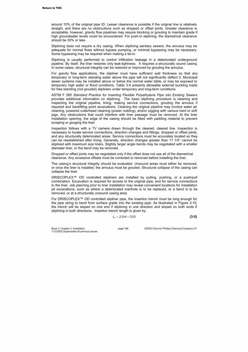
7/23/2019 The Performance Pipe Engineering Manual
http://slidepdf.com/reader/full/the-performance-pipe-engineering-manual 169/208
Book 3: Chapter 3: Installation page 166 ©2002 Chevron Phillips Chemical Company LP1/12/2002 Supercedes all previous issues
around 10% of the original pipe ID. Lesser clearance is possible if the original line is relativelystraight, and there are no obstructions such as dropped or offset joints. Greater clearance isacceptable, however, gravity flow pipelines may require blocking or grouting to maintain grade if high groundwater levels could be encountered. For push-in sliplining, the diametrical clearanceshould be 30% or less.
Sliplining does not require a dry casing. When sliplining sanitary sewers, the annulus may beadequate for normal flows without bypass pumping, or minimal bypassing may be necessary.Some bypassing may be required when making a tie-in.
Sliplining is usually performed to control infiltration leakage in a deteriorated undergroundpipeline. By itself, the liner restores only leak-tightness. It requires a structurally sound casing.In some cases, structural integrity can be restored or improved by grouting the annulus.
For gravity flow applications, the slipliner must have sufficient wall thickness so that anytemporary or long-term standing water above the pipe will not significantly deflect it. Municipalsewer systems may be installed above or below the normal water table, or may be exposed totemporary high water or flood conditions. Table 3-9 presents allowable external buckling loadsfor free standing (not grouted) slipliners under temporary and long-term conditions.
ASTM F 585 Standard Practice for Inserting Flexible Polyethylene Pipe into Existing Sewers provides additional information on sliplining. The basic sliplining procedure is cleaning andinspecting the original pipeline, lining, making service connections, grouting the annulus if required and backfilling point excavations. Cleaning the original pipeline may involve water jetcleaning, powered cutterhead cleaning (power rodding), and/or pigging with various hard or softpigs. Any obstructions that could interfere with liner passage must be removed. At the liner installation opening, the edge of the casing should be fitted with padding material to preventscraping or gouging the liner.
Inspection follows with a TV camera drawn through the cleaned, cleared line. Inspection isnecessary to locate service connections, direction changes and fittings, dropped or offset joints,and any structurally deteriorated areas. Service connections must be accurately located so theycan be reestablished after lining. Generally, direction changes greater than 11 1/4° cannot besliplined with maximum size liners. Slightly larger angle bends may be negotiated with a smaller diameter liner, or the bend may be removed.
Dropped or offset joints may be negotiated only if the offset does not use all of the diametricalclearance. Any excessive offsets must be corrected or removed before installing the liner.
The casing’s structural integrity should be evaluated. Unsound areas must either be removed,or once the liner is installed, the annulus must be grouted. Structural collapse of the casing cancollapse the liner.
DRISCOPLEX™ OD controlled slipliners are installed by pulling, pushing, or a push/pullcombination. Excavation is required for access to the original pipe, and for service connectionsto the liner. Job planning prior to liner installation may reveal convenient locations for installation
pit excavations, such as where a deteriorated manhole is to be replaced, or a bend is to beremoved, or at a structurally unsound casing area.
For DRISCOPLEX™ OD controlled slipliner pipe, the insertion trench must be long enough for the pipe string to bend from surface grade into the existing pipe. As illustrated in Figure 3-10,the trench will be sloped on one end if sliplining in one direction and sloped on both ends if sliplining in both directions. Insertion trench length is given by:
DH L 125.21 += (3-5)
Return to TOC
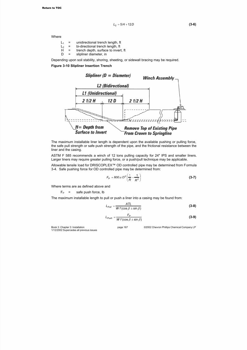
7/23/2019 The Performance Pipe Engineering Manual
http://slidepdf.com/reader/full/the-performance-pipe-engineering-manual 170/208
Book 3: Chapter 3: Installation page 167 ©2002 Chevron Phillips Chemical Company LP1/12/2002 Supercedes all previous issues
DH L 1252 += (3-6)
Where
L1 = unidirectional trench length, ft
L2 = bi-directional trench length, ftH = trench depth, surface to invert, ftD = slipliner diameter, in
Depending upon soil stability, shoring, sheeting, or sidewall bracing may be required.
Figure 3-10 Slipliner Insertion Trench
The maximum installable liner length is dependent upon the available pushing or pulling force,the safe pull strength or safe push strength of the pipe, and the frictional resistance between theliner and the casing.
ASTM F 585 recommends a winch of 12 tons pulling capacity for 24" IPS and smaller liners.Larger liners may require greater pulling force, or a push/pull technique may be applicable.
Allowable tensile load for DRISCOPLEX™ OD controlled pipe may be determined from Formula3-4. Safe pushing force for OD controlled pipe may be determined from:
−=
2
2 11800
R R DF P π (3-7)
Where terms are as defined above and
FP = safe push force, lb
The maximum installable length to pull or push a liner into a casing may be found from:
)sin(cos β β ±=
f W
ATLLPull (3-8)
)sin(cos β β ±=
f W
F L P
Push (3-9)
Return to TOC
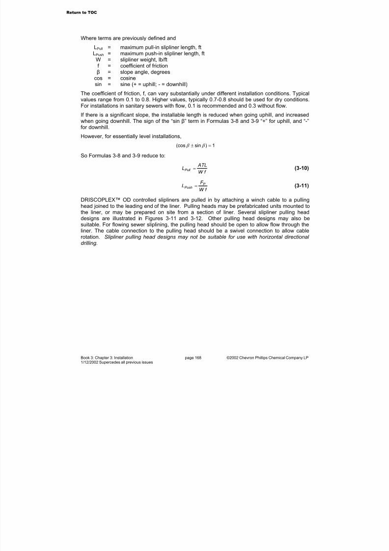
7/23/2019 The Performance Pipe Engineering Manual
http://slidepdf.com/reader/full/the-performance-pipe-engineering-manual 171/208
Book 3: Chapter 3: Installation page 168 ©2002 Chevron Phillips Chemical Company LP1/12/2002 Supercedes all previous issues
Where terms are previously defined and
LPull = maximum pull-in slipliner length, ftLPush = maximum push-in slipliner length, ftW = slipliner weight, lb/ftf = coefficient of friction
β = slope angle, degreescos = cosinesin = sine (+ = uphill; - = downhill)
The coefficient of friction, f, can vary substantially under different installation conditions. Typicalvalues range from 0.1 to 0.8. Higher values, typically 0.7-0.8 should be used for dry conditions.For installations in sanitary sewers with flow, 0.1 is recommended and 0.3 without flow.
If there is a significant slope, the installable length is reduced when going uphill, and increasedwhen going downhill. The sign of the “sin β” term in Formulas 3-8 and 3-9 “+” for uphill, and “-”for downhill.
However, for essentially level installations,
1)sin(cos =± β β
So Formulas 3-8 and 3-9 reduce to:
f W
ATLLPull = (3-10)
f W
F L P
Push = (3-11)
DRISCOPLEX™ OD controlled slipliners are pulled in by attaching a winch cable to a pullinghead joined to the leading end of the liner. Pulling heads may be prefabricated units mounted tothe liner, or may be prepared on site from a section of liner. Several slipliner pulling headdesigns are illustrated in Figures 3-11 and 3-12. Other pulling head designs may also be
suitable. For flowing sewer sliplining, the pulling head should be open to allow flow through theliner. The cable connection to the pulling head should be a swivel connection to allow cablerotation. Slipliner pulling head designs may not be suitable for use with horizontal directional drilling.
Return to TOC

7/23/2019 The Performance Pipe Engineering Manual
http://slidepdf.com/reader/full/the-performance-pipe-engineering-manual 172/208
Book 3: Chapter 3: Installation page 169 ©2002 Chevron Phillips Chemical Company LP1/12/2002 Supercedes all previous issues
Figure 3-11 Slipliner Pulling Heads Figure 3-12 "Banana Peel" Pulling Head
The leading end of the slipliner should be pulled past the termination point by 4-5% of the totalpull length, and the trailing end left long by the same amount. After the pull is completed, theliner should be allowed to relax for 24 hours before making final tie-ins. This over-pull length isnot required for push-in installations.
When sliplining sanitary sewers, the manhole-to-manhole distance may be a convenientinstallation length, however, pulls exceeding 4000 feet have been performed and pulling throughstraight-through manholes is routine practice.
DRISCOPLEX™ OD controlled slipliners may also be pushed in using a fabric choker slingaround the liner, hooked to a backhoe bucket as illustrated in Figure 3-13.
Figure 3-13 Backhoe Slipliner Push-In Technique
After liner installation, service connections are reestablished. Point excavations are usuallyrequired. Any branch connection appropriate for the service may be used. For a mechanicalbranch connection such as a strap-on saddle or an Inserta-Tee®, the casing crown down to thespringline must be removed to expose the top of the liner. For socket, saddle, or butt fusion to
Return to TOC

7/23/2019 The Performance Pipe Engineering Manual
http://slidepdf.com/reader/full/the-performance-pipe-engineering-manual 173/208
Book 3: Chapter 3: Installation page 170 ©2002 Chevron Phillips Chemical Company LP1/12/2002 Supercedes all previous issues
the liner, the entire casing must be removed for complete access to the liner. The pointexcavation and casing removal must provide clearance for equipment and personnel.
Once the service connection is completed, the casing to liner annulus must be sealed to preventbackfill migration and the area must be backfilled. The annulus may be sealed using amechanical seal, grout, concrete or cement-stabilized Class I or Class II soil. The point
excavation initial backfill is commonly cement-stabilized Class I or Class II soils, compactedClass I or Class II soils or concrete. Care should be taken to ensure the haunch areas are filledand compacted.
Sliplining with DRISCOPLEX™ 2000 SPIROLITE™ Pipe
DRISCOPLEX™ 2000 SPIROLITE™ liner pipe is jacked or pushed into the existing pipe, lengthby length. The diametrical clearance for DRISCOPLEX™ 2000 SPIROLITE™ sliplining mayvary, and is based on flow requirements through the liner, grout viscosity, and liner RSC.Installation requires a straight, clean casing pipe, without obstructions or dropped or offset joints. Bends and curves may be negotiated with DRISCOPLEX™ 2000 SPIROLITE™ S-links™, which are specially joined, short pipe sections.
Safe push force for DRISCOPLEX™ 2000 SPIROLITE™ pipe is based on pipe construction,
wall thickness, and joint design. Contact Performance Pipe Technical Services for informationon safe push force for DRISCOPLEX™ 2000 SPIROLITE™ pipe.
If groundwater will be above the casing pipe invert, the liner to casing annulus must be grouted.Grouting restores some or all of the casing structural integrity, prevents liner flotation, andmaintains the invert grade of the liner.
CAUTION. Grouting is a critical process. The liner may see its greatest loads duringgrouting. The project engineer should provide the installer with a specification for thegrouting process. Grout pressure must not exceed the collapse resistance of the liner.Improper grouting procedure can cause liner collapse. See Performance Pipe TechnicalNote PP 838-TN, Grout Encasement for DRISCOPLEX™ 2000 Spirolite™ Pipe in Casings and Tunnels for general information on grouting.
Preparation and planning for grouting includes consideration of blocks or skids, strutting or internal bracing, grout injection ports, and bypassing existing flows.
Equipment used to jack or push the pipe may be a telescopic ram, or a backhoe from above, or lengths may even be drawn in by pulling on a bar that spans across the pipe end with a winchedcable. Jacking equipment in the trench must be placed on a stable foundation of either stable,undisturbed native soil, or compacted foundation backfill. Lengths must be joined beforepushing into the casing, so the downstream length must be temporarily restrained againstlongitudinal movement while the next length is being joined into its bell. DRISCOPLEX™ 2000SPIROLITE™ pipe joint assembly is always spigot into bell, so jacking force must be evenlyapplied to the bell end of the length. See the Performance Pipe Technical Note PP 837-TN SPIROLITE™ Gasket Joint Assembly Procedure.
Return to TOC
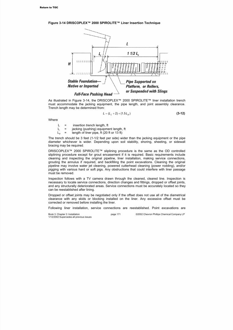
7/23/2019 The Performance Pipe Engineering Manual
http://slidepdf.com/reader/full/the-performance-pipe-engineering-manual 174/208
Book 3: Chapter 3: Installation page 171 ©2002 Chevron Phillips Chemical Company LP1/12/2002 Supercedes all previous issues
Figure 3-14 DRISCOPLEX™ 2000 SPIROLITE™ Liner Insertion Technique
As illustrated in Figure 3-14, the DRISCOPLEX™ 2000 SPIROLITE™ liner installation trenchmust accommodate the jacking equipment, the pipe length, and joint assembly clearance.Trench length may be determined from:
)5.1()2( p j LLL ++= (3-12)
Where
L = insertion trench length, ftL j = jacking (pushing) equipment length, ft
Lp = length of liner pipe, ft (20 ft or 13 ft)The trench should be 3 feet (1-1/2 feet per side) wider than the jacking equipment or the pipediameter whichever is wider. Depending upon soil stability, shoring, sheeting, or sidewallbracing may be required.
DRISCOPLEX™ 2000 SPIROLITE™ sliplining procedure is the same as the OD controlledsliplining procedure except for grout encasement if it is required. Basic requirements includecleaning and inspecting the original pipeline, liner installation, making service connections,grouting the annulus if required, and backfilling the point excavations. Cleaning the originalpipeline may involve water jet cleaning, powered cutterhead cleaning (power rodding), and/or pigging with various hard or soft pigs. Any obstructions that could interfere with liner passagemust be removed.
Inspection follows with a TV camera drawn through the cleaned, cleared line. Inspection isnecessary to locate service connections, direction changes and fittings, dropped or offset joints,and any structurally deteriorated areas. Service connections must be accurately located so theycan be reestablished after lining.
Dropped or offset joints may be negotiated only if the offset does not use all of the diametricalclearance with any skids or blocking installed on the liner. Any excessive offset must becorrected or removed before installing the liner.
Following liner installation, service connections are reestablished. Point excavations are
Return to TOC
7/23/2019 The Performance Pipe Engineering Manual
http://slidepdf.com/reader/full/the-performance-pipe-engineering-manual 175/208
Book 3: Chapter 3: Installation page 172 ©2002 Chevron Phillips Chemical Company LP1/12/2002 Supercedes all previous issues
required. Any branch connection appropriate to the service may be used. For a mechanicalbranch connection such as an Inserta-Tee®, the casing crown must be removed to expose thetop of the liner. The point excavation and casing removal must provide clearance for equipmentand personnel.
After the service connection is completed, the casing to liner annulus must be sealed to prevent
backfill migration and the area must be backfilled. The annulus may be sealed with grout,concrete or cement-stabilized Class I or Class II soil. Initial backfill should be with cement-stabilized Class I or Class II soils, compacted Class I or Class II soils, or concrete. Care shouldbe taken to ensure the haunch areas are filled and compacted.
Proprietary Trenchless Rehabilitation Techniques
A number of proprietary techniques use polyethylene pipe to rehabilitate a deteriorated or partially deteriorated host pipe. Tight-fitting liner techniques generally employ a mechanicalmeans to temporarily reduce the diameter of the liner by swaging, rolling-down, or deforming.The liner is pulled into the host pipe, and then expanded to fit closely to the host pipe insidediameter. The liner restores leak tightness, but the condition of the host pipe determines thestructural integrity of the rehabilitated pipeline. Tight fitting liners maximize the flow potential
through the rehabilitated line and minimize excavation, however, service connections may notbe leak tight.
In pipe bursting, a bursting head is attached to a polyethylene pipe string. When pulled into thehost pipe, the bursting head breaks the host pipe into pieces, enlarges the hole and draws anew pipe in the hole. Pipe bursting can provide increased capacity where the host pipe can beused as a guide path to install a larger pipe. Since the original host pipe is destroyed duringinstallation, the new pipe must be structurally designed for the necessary static and dynamicloads. Pipe bursting is limited to host pipes that can be fractured and appropriate soilconditions.
Surface Installations
Surface installations for Performance Pipe OD controlled pipe normally require fully restrained joints such as heat fusion, flanges and fully restrained mechanical couplings. Primaryinstallation considerations are to accommodate thermal expansion and contraction and tocontrol bending stresses and strains at rigid structures. Sunlight heating may requireelevated temperature pressure ratings.
Standard DRISCOPLEX™ 2000 SPIROLITE™ gasketed spigot and bell joints usually do notaccommodate enough thermal expansion movement for surface applications and generallyshould not be considered for surface applications. Contact Performance Pipe TechnicalServices for assistance with surface applications for DRISCOPLEX™ 2000 SPIROLITE™ pipe.
Under the summer sun, black polyethylene pipe may reach temperatures up to 140° F and maybe cooled to sub-zero temperatures in wintertime. In response to these temperature extremes,polyethylene pipe will expand and contract, both diametrically and longitudinally. For long pipingruns, thermal length changes can be very significant. See the Performance Pipe Engineering Manual, Book 2 System Design, Chapters 5 and 6 for design information.
Thermal length change may be accommodated with lateral deflection expansion loops that allowthe pipe to snake side to side. Expansion joints are not recommended.
Surface pipelines should be placed on a smooth, uniform bed, wide enough to accommodatelateral deflection movement. The bed should be free of large rocks, clumps, clods and projectingstones or debris. Continuous support is preferred, however, small ditches, and open spaces
Return to TOC
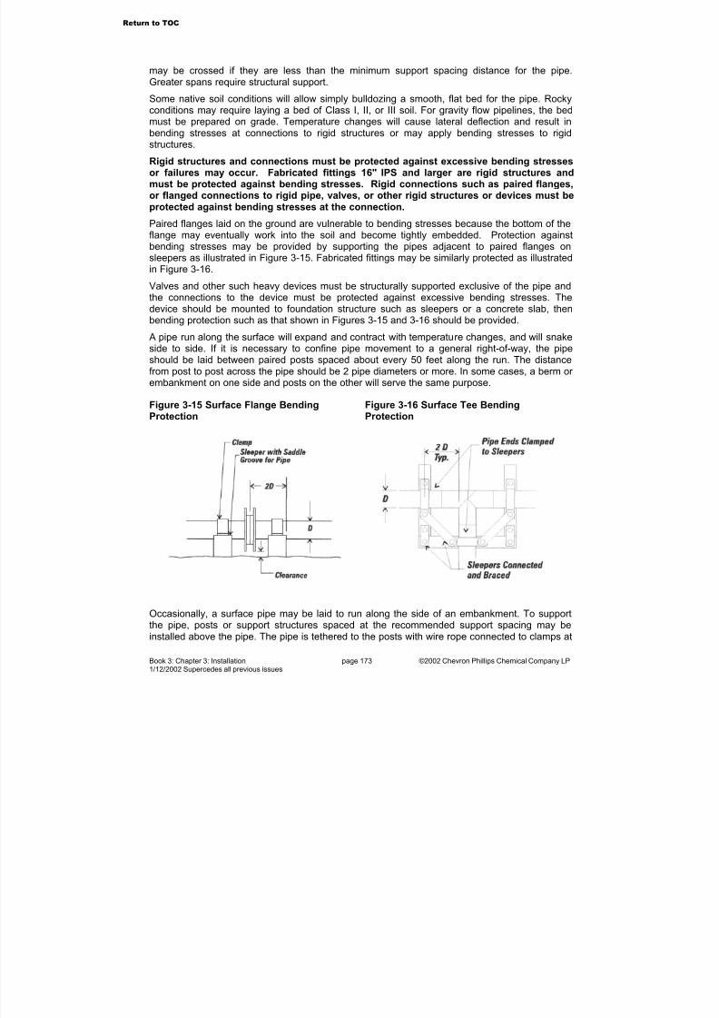
7/23/2019 The Performance Pipe Engineering Manual
http://slidepdf.com/reader/full/the-performance-pipe-engineering-manual 176/208
Book 3: Chapter 3: Installation page 173 ©2002 Chevron Phillips Chemical Company LP1/12/2002 Supercedes all previous issues
may be crossed if they are less than the minimum support spacing distance for the pipe.Greater spans require structural support.
Some native soil conditions will allow simply bulldozing a smooth, flat bed for the pipe. Rockyconditions may require laying a bed of Class I, II, or III soil. For gravity flow pipelines, the bedmust be prepared on grade. Temperature changes will cause lateral deflection and result in
bending stresses at connections to rigid structures or may apply bending stresses to rigidstructures.
Rigid structures and connections must be protected against excessive bending stressesor failures may occur. Fabricated fittings 16" IPS and larger are rigid structures andmust be protected against bending stresses. Rigid connections such as paired flanges,or flanged connections to rigid pipe, valves, or other rigid structures or devices must beprotected against bending stresses at the connection.
Paired flanges laid on the ground are vulnerable to bending stresses because the bottom of theflange may eventually work into the soil and become tightly embedded. Protection againstbending stresses may be provided by supporting the pipes adjacent to paired flanges onsleepers as illustrated in Figure 3-15. Fabricated fittings may be similarly protected as illustratedin Figure 3-16.
Valves and other such heavy devices must be structurally supported exclusive of the pipe andthe connections to the device must be protected against excessive bending stresses. Thedevice should be mounted to foundation structure such as sleepers or a concrete slab, thenbending protection such as that shown in Figures 3-15 and 3-16 should be provided.
A pipe run along the surface will expand and contract with temperature changes, and will snakeside to side. If it is necessary to confine pipe movement to a general right-of-way, the pipeshould be laid between paired posts spaced about every 50 feet along the run. The distancefrom post to post across the pipe should be 2 pipe diameters or more. In some cases, a berm or embankment on one side and posts on the other will serve the same purpose.
Figure 3-15 Surface Flange Bending
Protection
Figure 3-16 Surface Tee Bending
Protection
Occasionally, a surface pipe may be laid to run along the side of an embankment. To supportthe pipe, posts or support structures spaced at the recommended support spacing may beinstalled above the pipe. The pipe is tethered to the posts with wire rope connected to clamps at
Return to TOC

7/23/2019 The Performance Pipe Engineering Manual
http://slidepdf.com/reader/full/the-performance-pipe-engineering-manual 177/208
Book 3: Chapter 3: Installation page 174 ©2002 Chevron Phillips Chemical Company LP1/12/2002 Supercedes all previous issues
least 1/2 pipe diameter wide around the pipe.
Tethering may also be used to support a pipe running vertically up an embankment. The topconnection should be a structurally supported flange with bending protection. At an appropriatesupporting distance below the top flange, a flange pair should be installed for tether ropeconnections. At appropriate points to the side and above the tether connection flange, install
posts or structures, and connect tether ropes from the posts to the tether flange. Tether ropes,flanges and support posts can be installed as required along the vertical run.
Above Grade InstallationsLike surface installations, above grade installations of DRISCOPLEX™ OD controlled pipenormally require fully restrained joints. Primary considerations are to accommodate thermalexpansion and contraction and to control bending stresses at rigid structures. Sunlight heatingmay require elevated temperature pipe pressure ratings.
DRISCOPLEX™ 2000 SPIROLITE™ pipe generally should not be considered for surfaceapplications. Standard DRISCOPLEX™ 2000 SPIROLITE™ gasketed spigot and bell jointsusually do not accommodate enough thermal expansion movement and do not provide sufficientrestraint for above grade installations. Contact Performance Pipe Technical Services for assistance with surface applications for DRISCOPLEX™ 2000 SPIROLITE™ pipe.
Above grade piping may be either supported in racks or hung from overhead supports. Racksmust be wide enough to accommodate deflection from thermal expansion. If the rack is toonarrow, the pipe may expand enough to fall off, or jump out, or damage adjacent piping or structures. Expansion joints generally provide unsatisfactory service with polyethylene pipe andare not recommended. Polyethylene pipe tends to deflect laterally rather than generate reactivethrust that would close the expansion joint. In pressure service, expansion joints simply expandout and cause further pipe deflection.
Rack beams supporting the pipe must be spaced at the recommended support spacing or less.See the Performance Pipe Engineering Manual, Book 2, System Design, Chapter 6 for specificinformation on rack design. See the Performance Pipe Engineering Manual, Book 2, System
Design, Chapter 5 for thermal expansion and contraction information.
Figures 3-17 and 3-18 illustrate examples of rack designs. Center anchored pipes deflect toeither side of the centerline. Pipe anchors must pivot with pipe deflection. Side anchored pipesdeflect to one side only and anchors can be fixed to the one side.
Return to TOC
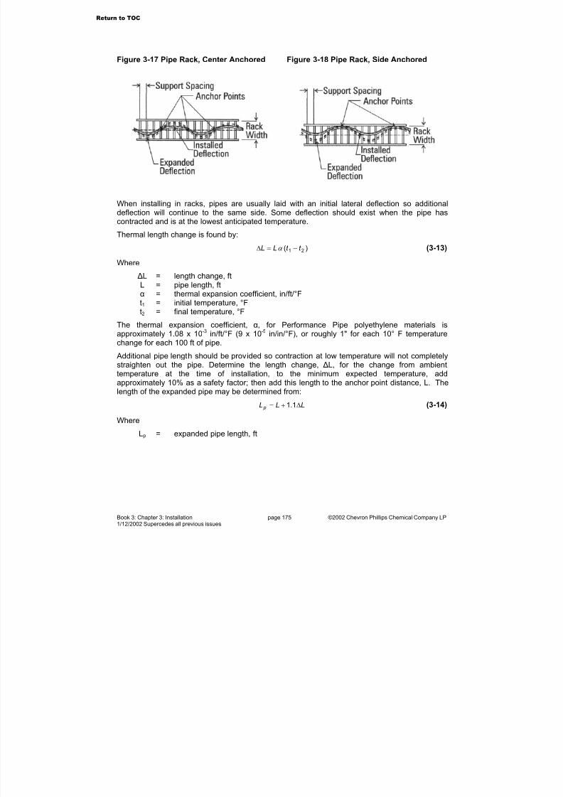
7/23/2019 The Performance Pipe Engineering Manual
http://slidepdf.com/reader/full/the-performance-pipe-engineering-manual 178/208
Book 3: Chapter 3: Installation page 175 ©2002 Chevron Phillips Chemical Company LP1/12/2002 Supercedes all previous issues
Figure 3-17 Pipe Rack, Center Anchored Figure 3-18 Pipe Rack, Side Anchored
When installing in racks, pipes are usually laid with an initial lateral deflection so additional
deflection will continue to the same side. Some deflection should exist when the pipe hascontracted and is at the lowest anticipated temperature.
Thermal length change is found by:
)( 21 t t LL −=∆ α (3-13)
Where
∆L = length change, ftL = pipe length, ftα = thermal expansion coefficient, in/ft/°Ft1 = initial temperature, °Ft2 = final temperature, °F
The thermal expansion coefficient, α, for Performance Pipe polyethylene materials isapproximately 1.08 x 10⁻³ in/ft/°F (9 x 10⁻⁵ in/in/°F), or roughly 1" for each 10° F temperaturechange for each 100 ft of pipe.
Additional pipe length should be provided so contraction at low temperature will not completelystraighten out the pipe. Determine the length change, ∆L, for the change from ambienttemperature at the time of installation, to the minimum expected temperature, addapproximately 10% as a safety factor; then add this length to the anchor point distance, L. Thelength of the expanded pipe may be determined from:
LLL p ∆+= 1.1 (3-14)
Where
Lp = expanded pipe length, ft
Return to TOC

7/23/2019 The Performance Pipe Engineering Manual
http://slidepdf.com/reader/full/the-performance-pipe-engineering-manual 179/208
Book 3: Chapter 3: Installation page 176 ©2002 Chevron Phillips Chemical Company LP1/12/2002 Supercedes all previous issues
Figure 3-19 Deflected Pipe Installation
Above grade pipelines may also be suspended from hangers. As illustrated in Figure 3-20,hangers should allow lateral deflection. Support should be at least 1/2 pipe diameter wide, andshould cradle the bottom 120° of the pipe.
Figure 3-20 Pipeline Hanger
Underwater InstallationUnderwater lines must be ballast weighted to prevent floatation. See the Performance PipeEngineering Manual, Book 2. System Design, Chapter 9 for ballast weight design. Ballastweights may be installed on shore or over water. The line is then floated into location and sunkinto position. Floats may be required to control sinking, or if the line is designed with heavyballast weights. However, typical ballast weight design allows an air-filled pipeline to float withballast weights attached if both ends of the pipeline are capped.
On shore ballast weight installation can be eased by using a skid way and sliding ballasted pipeinto the waterway. Over water, barge mounted cranes may be used to lift and move ballastweights and pipe.
Once ballasted, the pipeline is moved into position with marine craft or pulled into position withcables. Temporary anchoring may be used to maintain position during sinking. Water isintroduced from the shore end, and air bled out slowly from the opposite end. Water must not beallowed to run the full length of the pipe. The shore end should be raised slightly to create a u-bend of water that moves down the line as the line sinks. The floating air bleed end should beelevated above the water to prevent water entry. Bleeding air from the floating end controls thewater entry rate. Sinking rate must be controlled so the pipe does not bend too tightly and kink.
Return to TOC

7/23/2019 The Performance Pipe Engineering Manual
http://slidepdf.com/reader/full/the-performance-pipe-engineering-manual 180/208
Book 3: Chapter 3: Installation page 177 ©2002 Chevron Phillips Chemical Company LP1/12/2002 Supercedes all previous issues
If the pipeline is to be buried, all trench excavations must be performed before sinking. To aid inplacement, underwater backfill should be coarse soil such as gravel or crushed rock. If additional erosion protection is necessary, riprap, such as large stones or broken pavement,may be placed over the initial backfill.
Floating PipelinesPipelines for dredging or for discharging slurries into impoundments may be required to float onor above the surface. Polyethylene is about 4.5% lighter than water, so the pipe will float whenfilled with water. However, liquid slurries may be heavy enough to sink the line.
When the pipeline is supported above the surface, the floats must support their own weight andthe weight of the pipeline and its contents. When floated at the surface, the displacement of thepipeline in the water reduces floatation requirements. Figures 3-21 and 3-22 illustrate floatattachment methods.
Figure 3-21 Flotation Above the Surface Figure 3-22 Flotation On the Surface
Polyethylene Pipe for Flotation
DRISCOPLEX™ OD controlled pipe may be used for flotation to support pipelines above thewater or at the surface. Typically, floats are pipe lengths that are capped on the ends. Floatscan be filled with lightweight foam so that physical damage will not allow the float to fill withwater and impair its ability to support a load.
Float sizing is an iterative process because the float must support itself as well as the load. Thefirst step is to determine the load, and choose an initial size for the float.
Step 1. Load Determination
The supported load is the weight of the pipeline and its contents plus the weight of the float andthe structure for attaching the float to the pipeline. If the float is foam-filled, the weight of thefoam must also be included.
M F SC P W W W W W P ++++= (3-15)
Where
Return to TOC
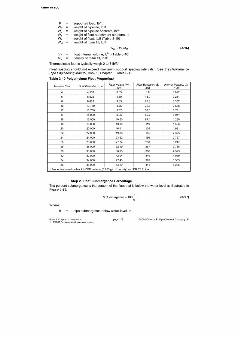
7/23/2019 The Performance Pipe Engineering Manual
http://slidepdf.com/reader/full/the-performance-pipe-engineering-manual 181/208
Book 3: Chapter 3: Installation page 178 ©2002 Chevron Phillips Chemical Company LP1/12/2002 Supercedes all previous issues
P = supported load, lb/ftWP = weight of pipeline, lb/ftWC = weight of pipeline contents, lb/ftWS = weight of float attachment structure, lbWF = weight of float, lb/ft (Table 3-10)WM = weight of foam fill, lb/ft
M F M M V W = (3-16)
VF = float internal volume, ft3/ft (Table 3-10)MM = density of foam fill, lb/ft3
Thermoplastic foams typically weigh 2 to 3 lb/ft3.
Float spacing should not exceed maximum support spacing intervals. See the PerformancePipe Engineering Manual, Book 2, Chapter 6, Table 6-1.
Table 3-10 Polyethylene Float Properties†
Nominal Size Float Diameter, d, inFloat Weight, W F ,
lb/ft Float Buoyancy, B,
lb/ft Internal Volume, V F ,
ft 3 /ft
4 4.500 0.83 6.9 0.097
6 6.625 1.80 14.9 0.211
8 8.625 3.05 25.3 0.357
10 10.750 4.75 39.3 0.555
12 12.750 6.67 55.3 0.781
14 14.000 8.05 66.7 0.941
16 16.000 10.50 87.1 1.230
18 18.000 13.30 110 1.556
20 20.000 16.41 136 1.921
22 22.000 19.86 165 2.325
24 24.000 23.62 196 2.767
26 26.000 27.74 230 3.247
28 28.000 32.19 267 3.766
30 30.000 36.93 306 4.323
32 32.000 42.04 349 4.919
34 34.000 47.43 393 5.553
36 36.000 53.20 441 6.225
† Properties based on black HDPE material (0.955 g/cm3
density) and DR 32.5 pipe.
Step 2. Float Submergence Percentage
The percent submergence is the percent of the float that is below the water level as illustrated inFigure 3-23.
d
heSubmergenc 100% = (3-17)
Where
h = pipe submergence below water level, in
Return to TOC

7/23/2019 The Performance Pipe Engineering Manual
http://slidepdf.com/reader/full/the-performance-pipe-engineering-manual 182/208
Book 3: Chapter 3: Installation page 179 ©2002 Chevron Phillips Chemical Company LP1/12/2002 Supercedes all previous issues
d = pipe diameter, in (Table 3-10)
Figure 3-23 Float Submergence
The designer should choose an appropriate percent submergence and submergence margin.For the floats in Table 3-10, submergence margins are shown in Table 3-11. If the percentsubmergence is too high, point-loaded floats may deflect at the load center and be more deeply
submerged at the load center compared to unloaded areas.
Table 3-11 Submergence Margin
% Submergence Submergence Margin
55% 2
43% 3
37% 4
Step 3. Float Support Capacity
Determine the float buoyancy, B, from Table 3-10 for the initial float size. Then determine the
submergence factor, f S, from Table 3-12.
Table 3-12 Submergence Factor, f S
Submergence Submergence Submergence Submergence
Percent Factor, f S Percent Factor, f S Percent Factor, f S Percent Factor, f S
5 0.019 30 0.252 55 0.564 80 0.858
10 0.052 35 0.312 60 0.623 85 0.906
15 0.094 40 0.377 65 .0688 90 0.948
20 0.142 45 0.436 70 0.748 95 0.981
25 0.196 50 0.500 75 0.804 100 1.000
Determine the load supporting capacity of the float, PF.
Bf P SF = (3-18)
Where
PF = float load supporting capacity, lb/ftf S = submergence factor from Table 3-12B = buoyancy from Table 3-10
Return to TOC

7/23/2019 The Performance Pipe Engineering Manual
http://slidepdf.com/reader/full/the-performance-pipe-engineering-manual 183/208
Book 3: Chapter 3: Installation page 180 ©2002 Chevron Phillips Chemical Company LP1/12/2002 Supercedes all previous issues
Step 4. Compare Float Support Capacity to Load
The support capacity of the float must equal or exceed the load it is to support.
P P F ≥ (3-19)
If the load, P, is greater than the float support capacity, PF, choose a larger float and repeatSteps 1, 2 and 3. If the float support capacity, P
F, is significantly greater than the load, P, a
smaller float may be adequate.
Step 5. Check Actual Float Submergence
Once the proper float size has been determined, check the actual float submergence.
B
P f SA = (3-20)
Where
f SA = actual float submergence factor
The actual float submergence factor, f SA, may be compared to the values in Table 3-12 to
determine the approximate percent submergence.
Go to Chapter 4
Return to TOC

7/23/2019 The Performance Pipe Engineering Manual
http://slidepdf.com/reader/full/the-performance-pipe-engineering-manual 184/208
Book 3: Chapter 4: Inspection & Testing page 181 ©2002 Chevron Phillips Chemical Company LP1/12/2002 Supercedes all previous issues
4. Inspection & Testing
Pre-ConstructionInspections and tests begin before construction. Jobsite conditions dictate how piping may be
installed and what equipment is appropriate for construction. Soil test borings and testexcavations may be useful to determine soil bearing stress and whether or not native soils aresuitable as backfill materials.
In slipline rehabilitation applications, the deteriorated pipeline should be inspected by remote TVcamera to locate structurally deteriorated areas, obstructions, offset and separated joints,undocumented bends and service connections. In some cases, a test pull, drawing a shortsection of slipliner through the line, may be conducted to ensure that the line is free of obstructions.
The contractor should carefully inspect contract specifications and plans. It is important that thespecifications and plans fit the job. Different piping materials require different constructionpractices and procedures. These differences should be accurately reflected in the contract
documents. Good plans and specifications help protect all parties from unnecessary claims andliabilities. Good documents also set minimum installation quality requirements and the testingand inspection requirements that apply during the job.
As presented in the Performance Pipe Engineering Manual, Book 3, Chapter 1, “Handling andStorage,” all incoming materials should be inspected to be sure that sufficient quantities of thecorrect products for the job are at hand and that they arrived in good condition, ready for installation.
For critical jobs, an inspection of the manufacturer's facilities may be in order. The manufacturer should have an established reputation for quality products, should have a detailed, well-documented quality control and quality assurance program and should have adequate facilitiesto make the size and quantities required.
During ConstructionTests and inspections performed during construction include butt fusion joint quality tests; soilcompaction and density tests; pipe deflection tests, pressure tests and other relevantinspections.
Butt Fusion Joint Quality
Visual inspection is the only reliable non-destructive joint evaluation test applicable to all sizesof OD controlled Pipe. Non-destructive tests such as microprocessor controlled ultrasonicinspection may be available for selected sizes. X-ray inspection is generally unreliable becausex-ray is a poor indicator of cold fusion.
Butt fusion joints are visually inspected to ensure joint quality. The size and shape of theexternal fusion beads indicate if a proper joint has been made. As illustrated in Figure 4-1, a)the double bead width should be 2 to 2-1/2 times the height from the pipe surface, b) bothbeads should be uniform in size and shape all around the joint, and c) the depth of the v-groovebetween the beads must not be more than half the bead height.
If the v-groove is too deep, a “cold” fusion may be indicated. Cold fusion results when most of the melt is pressed out of the joint. It is caused by insufficient heating (heating iron too cold or cold spots or insufficient heating time), or excessive pressure during heating, or excessive
Return to TOC

7/23/2019 The Performance Pipe Engineering Manual
http://slidepdf.com/reader/full/the-performance-pipe-engineering-manual 185/208
Book 3: Chapter 4: Inspection & Testing page 182 ©2002 Chevron Phillips Chemical Company LP1/12/2002 Supercedes all previous issues
pressure during joining. A non-uniform bead shape around the pipe indicates uneven heating,possibly from cold spots on the heating iron surface.
Figure 4-1 Butt Fusion Bead – Visual Inspection Guidelines
Cold fusion is a poor quality joint that should be removed and re-done. If not repaired, jointfailure can occur.
When butt fusion is between pipe and molded fittings, the fitting-side bead may exhibit shapeirregularities that are caused by the fitting manufacturing process. A slightly irregular fitting-sidebead may not indicate an improper joint, provided that the pipe-side bead is properly shaped,and the v-groove between the beads is correct. Contact Performance Pipe Technical Services if assistance is required.
During construction fusion joining, Performance Pipe recommends that the installer shouldverify operator procedure, equipment set-up and field fusion quality by making and testing a trialfusion. The trial fusion is allowed to cool completely; then test straps are cut out and bent straptested in accordance with ASTM D 2657. If the bent strap test of the trial fusion fails at the joint,
any field fusions represented by the trial fusion should be redone.
The bent strap test specimen is prepared by making a trial butt fusion, and allowing it to cool toambient temperature. A test strap that is at least 6" or 15 pipe wall thicknesses long on eachside of the fusion, and 1-1/2 wall thicknesses (at least 1") wide is cut out of the trial fusion pipe.See Figure 4-2. The strap is then bent so that the ends of the strap touch. Any disbondment atthe fusion is unacceptable and indicates poor fusion quality. If failure occurs, fusion proceduresand/or machine set-up should be changed, and a new trial fusion and bent strap test specimenprepared and tested.
Figure 4-2 Bent Strap Test Specimen
Return to TOC

7/23/2019 The Performance Pipe Engineering Manual
http://slidepdf.com/reader/full/the-performance-pipe-engineering-manual 186/208
Book 3: Chapter 4: Inspection & Testing page 183 ©2002 Chevron Phillips Chemical Company LP1/12/2002 Supercedes all previous issues
A test strap from thick wall pipe may require considerable effort to bend. Further, the teststrap may spring back if the ends are inadvertently released while bending. Appropriatepersonnel safety precautions should be observed.
Additional information and guidelines for evaluating butt, socket and saddle fusions arepresented in Performance Pipe Bulletin PP-750 Performance Pipe Heat Fusion Joining
Procedures.
Soil Tests
During buried pipe installation, work should be checked throughout the construction period byan inspector who is thoroughly familiar with the jobsite and the contract specifications, materials,and installation procedures. Inspections should reasonably ensure that significant factors suchas trench depth, grade, pipe foundation (if required), quality and compaction of embedmentbackfill, and safety are in compliance with contract specifications and other requirements.
To evaluate soil stability, density and compaction, appropriate ASTM tests may be required inthe contract specifications.
Surface Damage
Surface damage may occur during construction handling and installation. Significant damagemay impair the future performance of the pipeline. The following guidelines may be used toassess damage significance.
For DRISCOPLEX™ pressure piping systems, damage or butt fusion misalignment in excess of 10% of the minimum wall thickness required for pipeline operating pressure may be significant.If the pipeline is to operate at the maximum permissible pressure for the material and DR, thedamage allowance is 10% of the pipe minimum wall thickness. On the other hand, if the pipe isto operate at lower pressure, damage depth may be greater.
Excessive damage may require removal and replacement of the damaged pipe section, or reinforcement with a full encirclement repair clamp. Damaged pipe cannot be “repaired” by filling
damaged area with extrusion or hot gas welding. Misaligned butt fusions should be cut out andredone.
The shape of the damage should also be considered. For small damage areas where the depthis not excessive, sharp notches and cuts should be dressed smooth so the notch is blunted.Blunt scrapes or gouges should not require attention. Minor surface abrasion from sliding on theground or insertion into a casing should not be of concern.
Deflection Tests
Buried flexible pipes rely on properly installed backfill to sustain earthloads and other loads.Proper installation requires using proper backfill materials and installing the pipe as specified bythe designer. See the Performance Pipe Engineering Manual, Book 2. System Design, Chapter 7 for detailed information on buried flexible pipe design.
Deflection checks may be used to monitor the quality of installation. Improperly installed flexiblepipe can develop significant deflection in a short time, thus alerting the installer and theinspector to investigate the problem. Inspection should be performed as the job progresses; thatway, any errors in the installation procedure can be identified and corrected.
Initial deflection checks may be performed after embedment materials have been placed andcompacted. Procedures for determining deflection are presented in Performance Pipe TechnicalNote PP 817-TN Checking Vertical Deflection of Gravity-Flow Pipe.
Return to TOC

7/23/2019 The Performance Pipe Engineering Manual
http://slidepdf.com/reader/full/the-performance-pipe-engineering-manual 187/208
Book 3: Chapter 4: Inspection & Testing page 184 ©2002 Chevron Phillips Chemical Company LP1/12/2002 Supercedes all previous issues
Leak Testing
Recommended leak testing procedures for Performance Pipe polyethylene piping products arepublished in Performance Pipe Technical Note PP 802-TN Leak Testing. Contact anyPerformance Pipe Representative or Distributor for a copy.
Leak tests should not be confused with pressure tests. Leak tests using a pressurized fluid
media are intended to find leaks in a piping system.
Pressure tests are used with some piping materials to verify the pressure capacity of thepipeline. The pressure rating of polyethylene pipe, however, is based on long term sustainedpressure tests, not short-term material properties. For polyethylene pipe, short-term pressuretests cannot verify long-term performance and are incapable of verifying the pressure capacityof the pipeline.
If leak tests are required in the Contract Specifications, leak tests should be conducted inaccordance with Performance Pipe recommended procedures.
Liquids such as clean water are preferred as the test medium because less energy is released if the test section fails catastrophically. During a pressure test, energy (internal pressure) isapplied to stress the test section. If the test medium is a compressible gas, then energy is usedto compress the gas as well as apply stress to the pipeline. If a catastrophic failure occursduring a pneumatic test, both the pipeline stress energy and the gas compression energy areexplosively released. With an incompressible liquid as the test medium, the energy release isonly the energy required to stress the pipeline.
WARNING
Death or serious injury can result from failure at a joint or connection during leak testswith a liquid or gas under pressure. Keep all persons a safe distance away during testing. The test section is to be supervised at all times during the test.
Ensure that all piping is restrained against possible movement from catastrophic failureat a joint or connection. When pressurized, faulty joints or connections may separate
suddenly causing violent and dangerous movement of piping or parts. Correctly made joints do not leak. Leakage at a joint or connection may immediately precedecatastrophic failure. Never approach or attempt to repair or stop leaks while the test section is pressurized. Always depressurize the test section before making repairs.
Go to Chapter 5
Return to TOC

7/23/2019 The Performance Pipe Engineering Manual
http://slidepdf.com/reader/full/the-performance-pipe-engineering-manual 188/208
Book 3: Chapter 5: Operational Guidelines page 185 ©2002 Chevron Phillips Chemical Company LP1/12/2002 Supercedes all previous issues
5. Operational Guidelines
Disinfecting Water Mains Applicable procedures for disinfecting new and repaired potable water mains are presented in
standards such as ANSI/AWWA C651, Disinfecting Water Mains. ANSI/AWWA C651 usesliquid chlorine, sodium hypochlorite, or calcium hypochlorite to chemically disinfect the main.Disinfecting solutions containing chlorine should not exceed 12% active chlorine, becausegreater concentration can chemically attack and degrade polyethylene.
Cleaning Pipelines operating at low flow rates (around 2 ft/sec or less) may allow solids to settle in pipeinvert. Polyethylene has a smooth, non-wetting surface that resists the adherence of sedimentation deposits. If the pipeline is occasionally subject to higher flow rates, much of thesedimentation will be flushed from the system during these peak flows. If cleaning is required,sedimentation deposits can usually be flushed from the system with high-pressure water.
Water-jet cleaning is available from commercial services. It usually employs high-pressure water sprays from a nozzle that is drawn through the pipe system with a cable.
Pressure piping systems may be cleaned with the water-jet process or may be pigged. Pigginginvolves forcing a resilient plastic plug (soft pig) through the pipeline. Usually, hydrostatic or pneumatic pressure is applied behind the pig to move it down the pipeline. Pigging shouldemploy a pig launcher and a pig catcher.
A pig launcher is a wye or a removable spool. In the wye, the pig is fitted into the branch, thenthe branch behind the pig is pressurized to move the pig into the pipeline and downstream. Inthe removable pipe spool, the pig is loaded into the spool, the spool is installed into the pipeline,and then the pig is forced downstream.
A pig catcher is a basket or other device at the end of the line to receive the pig when it
discharges from the pipeline. A pig may discharge from the pipeline with considerablevelocity and force. A pig catcher provides a means of safe pig discharge from thepipeline.
Soft pigs must be used with polyethylene pipe. Scraping finger type or bucket type pigs willseverely damage the pipeline, and must not be used. Commercial pigging services areavailable if line pigging is required.
Frozen PipesWater can be frozen solid in polyethylene pipe without damaging the pipe, but an ice plug in thepipe will stop flow. Do not apply pressure to a frozen pipeline that has an ice plug because it can move the plug down the line at significant velocity. If the plug stops suddenly at an
obstruction, water hammer will result, which can burst or shatter the line.
WARNING -- Severe water hammer shock (such as from an ice plug stopping suddenly at an obstruction) in a frozen, surface or above grade pipeline can shatter the pipeline and flying fragments can cause death, injury or property damage. Allow an ice plug to thaw before applying pressure to the line.
Return to TOC
7/23/2019 The Performance Pipe Engineering Manual
http://slidepdf.com/reader/full/the-performance-pipe-engineering-manual 189/208
Book 3: Chapter 5: Operational Guidelines page 186 ©2002 Chevron Phillips Chemical Company LP1/12/2002 Supercedes all previous issues
Squeeze-Off Squeeze-off (or pinch-off) is a means of controlling flow in smaller diameter Performance PipeOD controlled pipe by flattening the pipe between parallel bars. Flow control does not implycomplete flow stoppage in all cases. For larger pipes, particularly at higher pressures, someseepage is likely. If the situation will not allow seepage, then it may be necessary to vent the
pipe between two squeeze-offs.Performance Pipe OD controlled Gas Pipe manufactured to ASTM D 2513 is suitable for squeeze-off; however, squeeze-off practices are not limited to gas applications. Squeeze-off isapplicable to OD controlled MDPE and HDPE pressure pipe up to 16" IPS and 100 psi internalpressure. Larger sizes and higher pressures may be possible, but suitable commercialequipment is not presently available, so there is no demonstrated experience with larger sizesor higher pressures.
Squeeze-off procedures that are recommended for Performance Pipe OD controlled pipe arepublished in Performance Pipe Technical Note PP-801-TN Polyethylene Pipe Squeeze-Off .Copies may be obtained from any Performance Pipe representative or distributor.
Additional information on squeeze-off may be found in ASTM F 1041 Standard Guide for
Squeeze-off of Polyolefin Gas Pressure Pipe and Tubing, ASTM F 1563 Specification for Toolsto Squeeze-Off Polyethylene (PE) Gas Pipe or Tubing and ASTM F 1734 Practice for Qualification of a Combination of Squeeze Tool, Pipe and Squeeze-Off Procedure to Avoid Long-Term Damage in Polyethylene (PE) Gas Pipe.
Static Electricity Control
When pipe conveying a compressed gas is being flattened, the gas flow velocity through theflattened area increases. High velocity, dry gas, especially with particles present in the flow, cangenerate a static electric charge on pipe surfaces that can discharge to ground. Beforeflattening the pipe, the tool should be grounded and procedures to control static charge build-upon pipe surfaces should be employed. Grounding and static control procedures should remain inplace for the entire procedure.
WARNING
Fire or Explosion – Static electricity discharge can ignite a flammable gas or combustibledust atmosphere. Where a flammable gas or combustible dust atmosphere may beencountered and static electric charges may be present such as during squeeze-off, leak repair, purging, making a connection, etc., arc preventing safety precautions arenecessary. Observe all Company (pipeline operator, utility, contractor, etc.) proceduresfor static electricity safety and control, including procedures for discharging static electricity and personal protection.
Routine or Emergency?Squeeze-off procedures may be used for routine, scheduled changes to piping systems, or asan emergency procedure to control gasses or liquids escaping from a damaged pipe. For scheduled piping changes, the above procedure should be followed, and if followed, the pipe’sservice life is not expected to be compromised.
However, an emergency situation may require quickly flattening the pipe and controlling flowbecause the escaping fluid may be an immediate hazard of greater concern than damaging the
Return to TOC

7/23/2019 The Performance Pipe Engineering Manual
http://slidepdf.com/reader/full/the-performance-pipe-engineering-manual 190/208
Book 3: Chapter 5: Operational Guidelines page 187 ©2002 Chevron Phillips Chemical Company LP1/12/2002 Supercedes all previous issues
pipe.
If an emergency situation requires rapid flattening, the pipe or tubing will probably be damaged.
RepairsRepair situations may arise if DRISCOPLEX™ OD controlled or DRISCOPLEX™ 2000
SPIROLITE pipe has been damaged. Damage may occur during shipping and handling, duringinstallation, or after installation. Damage may include scrapes or abrasions, breaks, punctures,kinks, or emergency squeeze-off. Permanent repair usually involves removing and replacing thedamaged pipe or fitting. However, temporary repairs may restore serviceability and allow time toeffect permanent repairs in the future.
Damage Assessment
Damage may be assessed according to guidelines presented in the Performance PipeEngineering Manual, Book 3, Chapters 1 and 4. Damaged pipe or fittings should be inspectedand evaluated to determine if the damage impairs serviceability.
• Pipe or fittings that have sustained service impairing damage should not be installed.
Post-installation damage may require that the damaged pipe or fitting be removed andreplaced.
• Scrapes or gouges cannot be repaired by filling-in with extrusion or hot air welding.The damaged section should be removed and replaced.
• Improperly made fusion joints cannot be repaired. Improper butt fusions must be cut outand re-done from the beginning. Poorly joined socket or electrofusion fittings must beremoved and replaced. Poorly joined saddle fittings must be removed by cutting out themain pipe section, or, if the main is undamaged, made unusable by cutting the branch outletor chimney off the saddle fitting, and installing a new saddle fitting on a new section of main.Socket fusion fittings cannot be reused.
• Broken or damaged fittings cannot be repaired. They must be removed and replaced.
• Kinked pipe must not be installed and cannot be repaired. Kinked pipe must beremoved and replaced.
• Pipe damaged during an emergency squeeze-off cannot be repaired. Squeeze-off damaged pipe must be removed and replaced.
Permanent Repairs
For buried large diameter Performance Pipe OD controlled or SPIROLITE pipe that has beenpoorly backfilled, excessive deflection may be correctable by removing and reinstalling backfillin accordance with recommended procedures.
Where replacement is required, any joining method appropriate to the product and service
requirements may be used. Butt and socket fusion to OD controlled pipe and butt fittingsrequires that one of the components move longitudinally. However, constrained installations,such as buried pipes, may not allow such movement. Permanent repairs of constrained pipesrequire techniques that do not require longitudinal movement. As illustrated in Figure 5-1,repairs may be effected by cutting out and replacing a section of pipe, or deflecting pipe ends tothe side and installing an appropriate coupling. Typical joining methods include flanges,electrofusion, and fully restrained mechanical couplings.
To repair using a flanged spool, cut out, remove and discard the damaged pipe section. Install
Return to TOC

7/23/2019 The Performance Pipe Engineering Manual
http://slidepdf.com/reader/full/the-performance-pipe-engineering-manual 191/208
Book 3: Chapter 5: Operational Guidelines page 188 ©2002 Chevron Phillips Chemical Company LP1/12/2002 Supercedes all previous issues
flanges on the two pipe ends. Measure the distance between the flange sealing surfaces, andprepare a flanged pipe spool of the same length. Install the flanged spool.
Repair using an electrofusion coupling or a fully restrained mechanical coupling is limited to pipesizes for which such couplings are available. Mechanical or electrofusion coupling repairs aremade by deflecting one pipe end to the side for the coupling body to be slipped on. The pipe
ends are then realigned, and the coupling joint fitted up. To allow lateral deflection, a length of about 10 times the pipe outside diameter is needed.
Figure 5-1 Constrained Pipe Repair
Temporary Repair
Temporary repairs may be needed to seal leaks or punctures, to restore pressure capacity, or toreinforce damaged areas until permanent repairs can be effected. Methods include but are notlimited to mechanical repair couplings and welded patches.
Go to TOC
Return to TOC
7/23/2019 The Performance Pipe Engineering Manual
http://slidepdf.com/reader/full/the-performance-pipe-engineering-manual 192/208
CPChem
a dia dia dia dia division of vision of vision of vision of vision of CheCheCheCheChevr vr vr vr vr on Phillips Chemical Companon Phillips Chemical Companon Phillips Chemical Companon Phillips Chemical Companon Phillips Chemical Company LPy LPy LPy LPy LP
PERFORMANCE PIPEPERFORMANCE PIPEPERFORMANCE PIPEPERFORMANCE PIPEPERFORMANCE PIPE
TM
©2002 Performance PipeTM
The Performance PipeTM
Engineering ManualTable of Contents
All rights reserved. This publicaiton is fully protected by copyright and nothing that appears in it may
be reprinted, copied, or otherwise reproduced by any means including electronic media, either wholly
or in part, without the express written permission of Performance PipeTM a division of Chevron Phillips
Chemical Company LP.
NOTICE -- This Manual is intended to be used as a guide to support the designer of polyethylene
piping systems. It is not intended to be used as installation instructions, and should not be substi-
tuted in place of the advice of a professional design engineer. There may be a more current version
of this manual. Contact Performance PipeTM for more informantion.
PLEXCO, PLEXVUE, and YELLOWSTRIPE are registered trademarks of Chevron Phillips
Chemical Company LP in the United States of America; BLUESTRIPE, CP CHEM, DRISCOPLEX,
GREENSTRIPE, PERFORMANCE PIPE, PLEXCO BLUESTRIPE, PLEXSHIELD, PLEXSTRIPE,
PURPLESTRIPE, REDSTRIPE, and SPIROLITE are trademarks of Chevron Phillips Chemical
Company LP in the United States of America.
7/23/2019 The Performance Pipe Engineering Manual
http://slidepdf.com/reader/full/the-performance-pipe-engineering-manual 193/208
Table Of Con tents
i
Preface i
Book 1: Engineering Properties
Chapter 1: About Performance Pipe
The Polyethylene Pipe Advantage 1
Identification Stripes and Colors 2
Colors to identify applications: 2
Color stripe patterns to identify sizing systems: 2
Color stripes to identify DR: 2
Solid Colors 3
Handling 3
Flexibility and Toughness 3Pressure Rating 4
Service Temperatures 4
Non-contaminating 4
Outstanding Chemical Resistance 4
Sealed Joints 4
Excellent Hydraulics 5
Surge and Liquid Velocity 5Abrasion Resistance 5
Thermal Expansion 6
Additional Information 6
Chapter 2: Performance Pipe Products
Piping Constructions 7
Sizing Systems 7
Third Party Certification and Listing 7Table 2-1 Performance Pipe DRISCOPLEX™ Products 8
Table 2-2 Markets and Typical Applications and Uses for 10
Performance Pipe M & I Piping Products

7/23/2019 The Performance Pipe Engineering Manual
http://slidepdf.com/reader/full/the-performance-pipe-engineering-manual 194/208
Table Of Con tents
ii
Chapter 3: Polyethylene Material Fundamentals
Polymerization 11
Fundamental Characteristics 11
Figure 3-1 Branched Polyethylene Molecule 11
Crystallinity (Density) 12
Figure 3-2 Crystalline and Amorphous Structure 12
Pigmentation Effects on Density 12
Molecular Weight 13
Molecular Weight Distribution 13
Figure 3-3 Molecular Weight Distribution and Modality 13
Understanding Property-Characteristic Interrelationships 14A Discussion of Table 3-1 14
Table 3-1 Physical Property Changes due to Fundamental 15
CharacteristicChanges
Graphical Illustrations of Interrelationships 15
Stiffness 16
Figure 3-4 Stiffness 16
Tensile Strength, Impact & Melt Viscosity 16
Figure 3-5 Yield Strength 16
Figure 3-6 Tensile Strength vs. Molecular Orientation 17
Figure 3-7 Property Change vs. Molecular Weight 17
Tensile Elongation 18
Figure 3-8 Tensile Elongation vs. Pulling Speed 18
Resistance to Slow Crack Growth 18
Figure 3-9 Resistance to Slow Crack Growth 18
Permeation 19
Figure 3-10 Resistance to Permeation 19
Hardness 19
Figure 3-11 Hardness 19
7/23/2019 The Performance Pipe Engineering Manual
http://slidepdf.com/reader/full/the-performance-pipe-engineering-manual 195/208
Table Of Con tents
iii
Chapter 4: Polyethylene Material Standards
Cell Classification Number 20
Long Term Strength 20
Table 4-1 ASTM D 3350 Properties and Cell Classification Limits 21
Material Designation Code 22
Performance Pipe Materials 23
Chapter 5: Environmental Effects
Resistance to Corrosion 24
Resistance to Stress Cracking 24
Biological Effects 24
Sunlight (Ultraviolet) Effects 24Thermal Effects 25
Chemical Effects 25
Resistance to Chemical Attack 25
Solvents and Suface Cleaning 26
Chemical Solvation (Permeation) 26
Chemical Attack 27
Chemical Resistance Information 27Chemical Reistance Key for Table 5-1 28
Table 5-1 Chemical Resistance 28
Chapter 6: Organizations, Standards & Publications
Organizations 35
Standards 35
Other Publications 37
7/23/2019 The Performance Pipe Engineering Manual
http://slidepdf.com/reader/full/the-performance-pipe-engineering-manual 196/208
Table Of Con tents
iv
Book 2: System Design
Chapter 1: Introduction
DRISCOPLEX™ Outside Diameter (OD) Controlled Polyethylene Pipe 38
DRISCOPLEX™ 2000 SPIROLITE Inside Diameter Controlled 39Polyethylene Pipe
Chapter 2: Stress Rated Materials
Table 2-1 Hydrostatic Design Basis Ratings and Service Temperatures 40
Chapter 3: Pressure Rating Design
Pipe Pressure Ratings 41
Table 3-1 Environmental Design Factors, f E
42
Table 3-2 Service Temperature Design Factors, f T
42
Fitting Pressure Ratings 42
Chapter 4: Fluid Flow
Application Limitations 43
Frozen Pipes 43
Pipe Internal Diameter 43
Pressure Flow of Liquids 44
Darcy-Weisbach/Colebrook/Moody 44
Table 4-1 Absolute Roughness for Commercial Pipe Materials 46
Figure 4-1 Moody Diagram 46
Fitting and Valve Friction Losses 46
Table Fitting Coefficient K’ 47
Hazen-Williams 47
Table 4-3 Properties of Water 48
Table 4-4 Hazen-Williams Friction Factor, C 48
Losses Due to Elevation Change 49
Air Binding and Vacuum Release 49
Water Hammer and Pressure Surge Considerations 49
Effects on Pressure Piping Systems 49
Surge Allowance 50
Table 4-5 Surge Allowance 50

7/23/2019 The Performance Pipe Engineering Manual
http://slidepdf.com/reader/full/the-performance-pipe-engineering-manual 197/208
Table Of Con tents
v
Working Pressure Rating (WPR) 51
Table 4-6 Surge Allowance 51
Effects of Cyclic Stressing 51
Controlling Water Hammer 51
Recommended Flow Velocities 52
Gravity Flow of Liquids 52
Manning 52
Table 4-8 Values of n for use with Manning Equations 54
Comparative Flows for Slipliners 54
Table 4-9 Comparative Flows for Slipliners 55
Pipe Surface Condition, Aging 55Slurry Flow 55
Particle Size 56
Solids Concentration and Specific Gravity 56
Critical Velocity 57
Table 4-10 Scale of Particle Sizes 58
Table 4-11 Specific Gravity and Slurry Solids Concentration 58
Table 4-12 Water-Base Slurry Specific Gravities 59Table 4-13 Velocity Coefficient, F
L(Uniform Particle Size) 59
Table 4-14 Velocity Coefficient, FL
(50% Passing Particle Size) 60
Head Loss 60
Compressible Gas Flow 60
High Pressure Formulas 60
Low Pressure Formulas 61
Gas Permeation 62Table 4-15 Permeability Constants 62
Table 4-16 Physical Properties of Gases 63
Chapter 5: Thermal Effects
Unrestrained Thermal Effects 64
End Restrained Thermal Effects 64

7/23/2019 The Performance Pipe Engineering Manual
http://slidepdf.com/reader/full/the-performance-pipe-engineering-manual 198/208
Table Of Con tents
vi
Table 5-1 Typical Elastic Modulus for DRISCOPLEXTM PE 3408 66
Controlling Expansion and Contraction 66
Lateral Deflection Expansion Loops 66
Table 5-1 Lateral Deflection 66
Table 5-2 Allowable Bending Strain 68
Figure 5-3 Midpoint and End Anchoring 68
Example 5-1 69
Anchored and Guided Pipe 70
Figure 5-4 Typical Guides 70
Example 5-2 71
Conventional Expansion Loops 73Figure 5-5 Conventional Expansion Loop 70
Example 5-3 74
Expansion Joints 75
Buried Piping Systems 75
Figure 5-6 Longitudinal Force Thrust Block 75
Heat Transfer 76
Table 5-3 Thermal Properties 76Chapter 6: Above Grade Supporting
Figure 6-1 Pipeline Supports 77
Figure 6-2 Pipeline Hanger 77
Figure 6-3 Deflection Between Supports 78
Support Spacing 78
Figure 6-5 Pipe Rack - Center Anchored 79
Figure 6-4 Pipe Rack - Side Anchored 79Pipe Rack Support 79
Table 6-1 Support Spacing 80

7/23/2019 The Performance Pipe Engineering Manual
http://slidepdf.com/reader/full/the-performance-pipe-engineering-manual 199/208
Table Of Con tents
vii
Chapter 7: Buried Pipe Design
General Design Procedure 81
Loads on Buried Pipe 82
Figure 7-1 Soil Prism 82
Dead Loads 82
Prism Load 82
Soil Arching 83
Figure 7-2 Soil Arching Development 83
Marston Load 83
Table 7-1 Typical Values for Ku’ 84
Soil Creep 84Example 7-1 85
Modified Arching Load 85
Figure 7-3 Arching Coefficient for Modified Arching Load 86
Surcharge Load 87
Distributed Load Over Pipe 87
Example 7-2 88
Figure 7-5 Illustration for Example 7-2 88
Table 7-2 Influence Coefficient, lc, for Distributed Loads Over Pipe 89
Distributed Load Not Over Pipe 89
Example 7-3 89
Figure 7-5 Illustration for Example 7-2 88
Vehicular Loads 90
Minimum Cover Depth 90
Highway Loads 90
Figure 7-7 AASHTO Standard H20 Static Loading 90
Figure 7-8 AASHTO Standard H20 Static Loading 91
Rigid Pavement Highway Loads 91
Table 7-3 H20 and HS20 Highway Loading (AISI) 91
Off-Highway and Unpaved Road Loads 92
Vehicular Loads As Point Loads 92
7/23/2019 The Performance Pipe Engineering Manual
http://slidepdf.com/reader/full/the-performance-pipe-engineering-manual 200/208
Table Of Con tents
viii
Single Wheel Load Centered On Pipe 92
Holl’s Intergration 93
Multiple Wheel Loads Along Pipe Length 93
Point Load On Pipe Crown 93
Table 7-4 Load Coefficient, Ch, for Holl’s Integration of 94
Boussinesq Equation
Figure 7-10 Concentrated Point Load 95
Example 7-5 95
Point Load Not On Pipe Crown 95
Multiple Wheel Loads on Rigid Pavement 96
Example 7-6 96
Figure 7-11 Illustration for Example 7-6 97
Vehicular Loads As Distributed Loads 97
Distributed Wheel Loads 97
Load Areas 97
Example 7-7 98
Timoshenko’s Method 99
Example 7-8 99
Railroad Loads 99
Table 7-5 Cooper E80 Live Load 100
Figure 7-13 Cooper E80 Live Loading 100
Designing Polyethylene Pipes to Withstand Loads 100
External Forces On Pipe 100
Constrained Pipe Wall Compressive Stress 101
Example 7-9 101
Unconstrained Pipe Wall Buckling 102
Ovality Effects 103
Figure 7-14 Ovality Compensation Factor for Unconstrained 104
Buckling
Example 7-10 104

7/23/2019 The Performance Pipe Engineering Manual
http://slidepdf.com/reader/full/the-performance-pipe-engineering-manual 201/208
Table Of Con tents
ix
Constrained Pipe Wall Buckling 105
Example 7-11 106
Ring Deflection 107
Soil Reaction Modulus, E´ 108
Table 7-7 Bureau of Reclamation Average E´ Values for 109
Iowa Forumula (Initial Deflection)
Table 7-8 Duncan-Hartley Soil Reaction Modulus 109
Lag Factor and Long Term Deflection 110
Example 7-12 110
Deflection Limits 110
Ring Bending Strain 112
Table 7-9 Safe Pressure Pipe Deflection 112
Example 7-13 112
Design Considerations For Shallow Cover Pipe 112
Shallow Cover Surcharge Load 112
Shallow Cover Buckling 113
Chapter 8: Groundwater Floation Effects
Table 8-1 Typical Soil Densities 115
Figure 8-1 Groundwater Flotation (Empty Pipe) 115
Groundwater flotation of Pipe 116
Figure 8-2 Pipe Liquid level 117
Groundwater flotation of Manholes 117
Figure 8-3 Anti-Flotation Anchor 118
Figure 8-4 Anti-flotation Anchor Installation 118
Table 8-2 Anti-Flotation Anchor Weights 118
Table 8-3 Upward Thrust of a Base, UTB
119
Table 8-4 Riser Upward Thrust per Vertical Foot of a Cover UTB
120
Table 8-5 Soil Weight Multipliers 120
Table 8-6 Soil Downward Force over Two Anti-Flotation 120
Anchors, DFA

7/23/2019 The Performance Pipe Engineering Manual
http://slidepdf.com/reader/full/the-performance-pipe-engineering-manual 202/208
Table Of Con tents
x
Table 8-7 Soil Downward Force Per Vertical Foot of Cover over Two 121
stub-outs, DFS
Table 8-8 Upward Thurst of Anchored Base, UTBA
121
Table 8-9 Frictional Resistance of soil Surrounding Riser for 122
selected Cover Depths, FRS
Chapter 9: Water Environment Design Considerations
External Hydraulic Pressure 123
Unconstrained Pipe Wall Buckling 123
Pipe Ovality Effects 123
Figure 9-1 Ovality Compensation Factor for Unconstrained Buckling 124
Table 9-1 Selected Conversion Factors 124
Table 9-2 Approximate External Pressure Resistance for OD Controlled 125
Pipe, Ib/in2
Submergence Weighting 126
Ballast Design for DRISCOPLEXTM OD Controlled Pipe 126
Table 9-3 Environmental Multiplier, K 126
Table 9-4 Specific Gravities and specific Weights of various liquids at 127
60°F (15°C)
Table 9-5 Pipe Weight Conversion Factors 127
Weight Shapes 128
Figure 9-2 Concrete Weight 128
Figure 9-3 Concrete Weight 128
Book 3: System Installation
Chapter 1: Handling and Storage
Receiving Inspection 129
Product Packaging 129
Figure 1-1 Typical Silo Pack Truckload (40’ Trailer) 129
Product Identification 130
Figure 1-2 Typical Bulk Pack Truckload (40’ Trailer) 130
Figure 1-3 Typical Strip Load Truckload (40’ Trailer) 131
Checking the Order 131
7/23/2019 The Performance Pipe Engineering Manual
http://slidepdf.com/reader/full/the-performance-pipe-engineering-manual 203/208
Table Of Con tents
xi
Load Inspection 131
Receiving Reports & Reporting Damage 132
Unloading Instructions 132
Unloading Site Requirements 132
Handling Equipment 132
Manholes and Tanks 133
Pre-Installation Storage 133
Figure 1-4 Forklift Load Capacity 133
Figure 1-5 Loose Pipe Storage 134
Pipe Stacking Heights 134
Table 1-1 Suggested Jobsite Loose Storage Stacking Height for OD 135Controlled Pipe
Table 1-2 Suggested Jobsite Loose Storage Stacking Heights for 135
CDRISCOPLEXTM 2000 SPIROLITE Pipe
Exposure to UV and Weather 135
Cold Weather Handling 135
Chapter 2: Joining & Connections
General Procedures 137
Cleaning 137
Cutting DRISCOPLEXTM OD Controlled Pipe 137
Cutting DRISCOPLEXTM 2000 SPIROLITE Pipe 138
Cutting Branch Outlet Holes 138
Fully Restrained Connections 138
Heat Fusion Joining 138
Socket Fusion 139
Saddle Fusion 139
Table 2-1 Field Saddle Fusion Size Guidelines 140
Table 2-2 Approximate Butt Fusion Joining Rates 140
Butt Fusion 140
Bead Removal 141
Electrofusion 141
7/23/2019 The Performance Pipe Engineering Manual
http://slidepdf.com/reader/full/the-performance-pipe-engineering-manual 204/208
Table Of Con tents
xii
Flange Connection 141
Figure 2-1 Flange Adapter and Back-Up Ring 142
Figure 2-2 Flange Adapter and Back-Up Ring 142
Flange Gasketing 142
Table 2-4 Typical Gasket Materials 143
Figure 2-3 Flange Gasket Styles 143
Flange Bolting 143
Table 2-3 Flange Dimensions (Inch Sized) 143
Figure 2-4 Bolt Length Parameters 143
Flange Installation 144
Figure 2-5 Buried Appurtenance Flange Foundation 144Figure 2-6 Flange Support at Wall 145
Special Cases 145
Thrust Restrained Mechanical Joints 145
ID Stiffeners for OD Controlled Pipe 145
DRISCOPLEXTM MJ Adapters 146
Partially Restrained Joints 146
Figure 2-7 DRISCOPLEXTM
MJ Adapter 146Figure 2-8 Insert Coupling 147
Figure 2-9 Mechanical Coupling with Insert Stiffeners 147
Unrestrained Joints 147
Figure 2-10 Partially Restrained Compression Coupling 148
Figure 2-11 External Joing Restraint 148
Special Joining Considerations 148
Other Joining Techniques 148Pipe Threads 148
Extrusion Welding 148
Hot Gas Welding 149
Manhole Connections 149
Branch Connections 149

7/23/2019 The Performance Pipe Engineering Manual
http://slidepdf.com/reader/full/the-performance-pipe-engineering-manual 205/208
Table Of Con tents
xiii
DRISCOPLEXTM OD Controlled Pressure Piping 149
Figure 2-12 Large Diameter Tee Installation 150
Figure 2-13 Tapping Sleeve 151
Outlets in Non-Pressure Piping 151
Figure 2-14 Inserta-Tee ® 151
Chapter 3: Installation
General Considerations 152
Underground Installations 152
Pipe Embedment Terminology 152
Figure 3-1 Trench Construction Terminology 153
Trenching 153Figure 3-2 Trench Width 154
Table 3-1 Minimum Trench Width 154
Figure 3-3 Trench Box Installation 154
Placing Pipe in the Trench 155
Cold (Field) Bending 155
Figure 3-4 Bend Radius 156
Table 3-2 Minimum cold Bending Radius for OD Controlled Pipe 156(Long-Term)
Table 3-3 DRISCOPLEXTM 2000 SpiroliteTM Curve Radius 156
Installing Fabricated Fittings 156
Pipe Embedment Soils 156
Table 3-4 Embedment Soil Classification 157
Embedment Backfilling 157
Figure 3-5 Haunch Tamping Tool 158
Joint Anchoring with Thrust Blocks 158
Table 3-5 Fitting Factor 159
Controlling Shear and Bending Loads at Rigid Structures 159
Figure 3-6 Controlling Shear and Bending 159
Figure 3-7 Flange Support at Wall 159
7/23/2019 The Performance Pipe Engineering Manual
http://slidepdf.com/reader/full/the-performance-pipe-engineering-manual 206/208
Table Of Con tents
xiv
Figure 3-8 Appurtenance Support Pad 160
Locating Tapes or Wires 160
Final Backfilling 160
Backfill Stabilizing Agents 160
Burrowing Animal Control 161
Special Installation Techniques 161
Plowing and Planting 161
Table 3-6 Minimum Short-Term Bending Radius 161
Pulling-in 162
Table 3-7 Recommended Design Factors 162
Table 3-8 Approximate Tensile Yield Strength Values 162Horizontal Boring 163
Figure 3-9 Split Back-Up Ring 164
Horizontal Directional Drilling (HDD) 164
Pipeline Rehabilitation Techniques 164
Conventional Sliplining (Insertion Renewal) With OD 164
Controlled Pipe
Table 3-9 Approximate Collapse Resistance for OD 165
Controlled Pipe, ft of water
Figure 3-10 Slipliner Insertion Trench 167
Figure 3-11 Slipliner Pulling Heads 169
Figure 3-12 “Banana Peel” Pulling Head 169
Figure 3-13 Backhoe Slipliner Push-In Technique 169
Sliplining with DRISCOPLEXTM 2000 SPIROLITETM Pipe 170
Figure 3-14 DRISCOPLEXTM 2000 SPIROLITETM Liner Insertion 171
TechniqueProprietary Trenchless Rehabilitation Techniques 172
Surface Installations 172
Figure 3-15 Surface Flange Bending Protection 173
Figure 3-16 Surface Tee Bending Protection 173
Above Ground Installations 174
7/23/2019 The Performance Pipe Engineering Manual
http://slidepdf.com/reader/full/the-performance-pipe-engineering-manual 207/208
Table Of Con tents
xv
Figure 3-17 Pipe Rack, Center Anchored 175
Figure 3-18 Pipe Rack, Side Anchored 175
Figure 3-19 Deflected Pipe Installation 176
Figure 3-20 Pipeline Hanger 176
Underwater Installation 176
Floating Pipelines 177
Figure 3-19 Flotation Above the Surface 177
Figure 3-19 Flotation On the Surface 177
Polyethylene Pipe for Flotation 177
Table 3-10 Polyethylene Float Properties 178
Figure 3-23 Float Submergence 179Table 3-11 Submergence Margin 179
Table 3-12 Submergence Factor, f s
179
Chapter 4: Inspection & Testing
During Construction 181
Butt Fusion Joint Quality 181
Figure 4-1 Butt Fusion Bead - Visual Inspection Guidelines 182
Figure 4-2 Bent Strap Test Specimen 182Soil Tests 183
Surface Damage 183
Deflection Teste 183
Leak Testing 184
Chapter 5: Operational Guidelines
Cleaning 185
Frozen Pipes 185Squeese-Off 186
Static Electricity Control 186
Routine or Emergency? 186
Repairs 187
7/23/2019 The Performance Pipe Engineering Manual
http://slidepdf.com/reader/full/the-performance-pipe-engineering-manual 208/208
Table Of Con tents
Damage Assessment 187
Permanent Repairs 187
Figure 5-1 Constrained Pipe Repair 188
Temporary Repair 188