the pfrc aerial ignition system
TRANSCRIPT

The PFRCAerial IgnitionSystem MARK II
••ForestryService
ISSN 0706·9413
ServIcedes For~ts
Part I - Development andDescription
Part II - Operational Manual
G.R. lan and S.J. Muraro
Vietoria. B.C.

- 2 -
ABSTRACT
A potassium perrnanganate-ethylene glycol incendiary devicedeveloped in Australia has been modified for use in an ignition systemappropriate to Canadian use. Part I provides background informationand a description for the incendiary device and dispenser. Pan II detailsinstallation and operational procedures for the system.
Un disposit if incendiaire contenant du permanganate et de I 'ethy
lene glycol, qui a eti mis au point en Asttalie, a ete modifie pour enfaire un allumeur d'usage canadien. Dans la premiere partie de I'article,Ie leeteur trouvera I'information de base ainsi qu'une description dudispositif incendiaire et de son apparel I distributeur. La seconde partiedefinit Ie processus d'installation et de fonctionnement de l'appareil.
TABLE OF CONTENTS
Pog,
PART I - DEVELOPMENT AND DESCRIPTION
1.0 Introduction..
2.0 The PFRC Aerial Ignition System ..
2.1 The AID (Aerial Ignition Device)
2.2 The MKII PFRC Aid Dispenser ...
4
4
5
7
2.2.1 Mode of Operation and Specifications. . . 8
2.2.2 Specification for the AID and MKII Dispenser. . . 11

·3·
PART It· OPERATIONAL MANUAL FOR THE MKII PFRCAID DISPENSER
1.0 Prepar at ion of Dispenser arn::l He heapter
2.0 Installation of AID Dispenser in the Helicopter ..
'2
14
3.0 Preflight Test .
3.1 Pilot Approval ....
3.2 To Start the Dispenser .....•.........
16
17
17
3.3 To Stop the Dispenser .. 18
3.4 Fire Extinguisher. . '8
3.6 Communication Systems. '8
4.0 Operational Procedures and Restrictions
4.1 Pilot Instruction ..
4.2 Inflight Operation ....
4.3 Operational Malfunctions ........•..
19
19
19
20
5.0 Maintenance and Repair . 21
6.0 References. 21
7.0 Appendill: I . Trouble Shooting the MKII Dispenser. . 23
8.0 Appendix II· SUgJested Field Service Tools andSupplies. . . . . . . . . . . . . . . . . . . 25
9.0 Appendix III - Precautions for Shipping and StoringPotassium Permanganate. . . . 26

·4·
PART I
DEVELOPMENT AND DESCRIPTION
1·1.0 INTRODUCTION
Aerial Ignition systems used for land management purposes utilizeone of three ty~ of inCerldiaries: burning hydrocarbons. launched or freedropped pyrotechnical devices, and those that utilize an exothermicchemical reaction. The first is generally used for ignition of a continuousline of fire where lorest covef does not impede ignition. The others arepoint ignition devices that allow manipulation of fire behavior and aresuitable for use in the open or where penetration of a forest canopy isnecessary. Chemical incendiaries used for wildland management are presently limited to the relatively stable potassium permanganate-ethyleneglycol type.
The potassium permanganate-ethylene glycol incendiaries werefirst developed and used in Australia for underburning large tracts ofJarrah forests for hazard abatement (Baxter et al. 1966; Packham andPeet 19671. Later these incendiaries and other air·borne devices were usedfor suppression burning in Australia (Hodgson and Cheney 19701, Canada(lait and Taylor 1972) and the United States (Lott 19731. In NorthAmerica, aerial ignition has been used for prescribed burns for poS!: loggingtreatment (Fielder 1975). vegetation manipulation for habitat (leege andFultz 1972) and fuels management (Sackett 19751.
1·2.0 THE PFRC AERIAL IGNITION SYSTEM
This ignition system consists of a chemical ignition device, thepriming and dispensing mechanism, the dispenst'r operator and the pilotarn;:l aircraft. Development has been oriented toward improving the auto·mated handling characteristics of the ignition device and to improving thesafety. speed and reliability of the priming and dispensing equipment.
Although the system described here was developed at the PacificForest Research Centre, it incorporates ideas and techniques from manysources.
1·2,1 The Atd (Aeriallgnitton Device)
The first operational Canadian adaPtation of the Australian igni·

- 5 -
tion device utilized pharmaceutical vials to contain the potassium permanganate (Lait and Taylor 1972). These vials Ir'/iUe satisfactory for manualdispensers but their irregular shape caused malfunctions of faster machines.A spherical container, introduced by the Alberta Department of Landsand Forests, Equipment Development Section, appeared more practicaland has been modified for use in the PFRC Dispenser. Tests of styrenespheres at the Pacific Forest Research Centre indicated that a sphere32 mm (1.25 in) in diameter optimized oost and ignition characteristics.Subsequently an inieetion type mold was designed and constructed undercontract by a Victoria manufacturer. The first production run of sphereswas of low impact polystyrene, a brittle material that caused dispensermalfunction. Subsequent tests of both polyethylene and the more mal·leable high impact polystyrene showed the latter to be much superior.The final product, termed AID (Aerial Ignition Device), consists of approx,imately 3.0 grams of potassium permanganate contained by twO perma·nently sealed hemispheres of high impact polystyrene.
The rate of a chemical reaction is dependent on the concentrationand particle size of the chemicals involved. The high proportion of finesin the commercial grade of potassium permanganate reacts with 1.0 mlof full strength ethylene glycol to produce flaming combustion in about5 seconds. Water-glycol solutions ranging from 75 to 25 percent glycolwere tested to determine concentrations that would provide a time interval of at least 20 seronds. A 50 percent concentration of glycol is advo·cated as it provides reliable ignition with a time delay of 25 secondsand is easy to measure and mix. Unreliable ignition occurs at concentra·tions of less than 33 percent glycol. The quantity of glycol solution isnot critical within the range of 0.5 to 2.0 mi. Lesser or greater quantitiesdo not ignite or ignite very slowly and cannot be relied on.
Commercial grade ethylene glycol is readily available from chemical supply houses and commercially prepared AIDs are available through aVictoria manufacturerll at a reasonable cost. They are packed and labelledto meet current International Air Transport Association regulationsregarding transport of restricted articles. Shipping weight is approximately7.0 kg per case of 1.000 units containing a net weight of 3.0 kg of KMn04per case. This configuration allows a maximum of four cases or 4,000AIDs to be carried by passenger aircraft under current lATA regulations.
Additional specifications of the AID are provided on page 11 andprecautions for shipping. storing and handling potassium permanganateare listed in Appendix Ill.
U Premo Plutics Ef"llIineering Ltd.,863 V~ieldAOIId, Viaoria, B.C., V9A 4V2.
·6·
•
----,
'I '~- t---t-~N N
,
~
.~-_..., .'Il )11', ,, .J
.- -...,<> , ,
\ ' ,J ' ,. "~, ,1\ )--~, , ,'I • I
I I \)l, ,,'.
\
I,/
t..

- 7 -
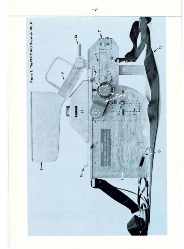
1- 2.2 The MKII PFRC Aid Dispenser
The function of the Dispenser is to inject the glycol into the
AID, thereby initiating the exothermic reaction, and to expel the primed
AIDs from the aircrah. It has been designed to accomplish this with minimum operator manipulation and a high degree of safety and reliability.
It is currently accepted for installation in the Bell 206 and in the Hughes
500 type helicopters. The main components shown in Figure 1 are;
(1) glycol storage tank
(2) glycol pump
(3l drive motor
(4) chain drive (under guard) with manual assist(5) cams(6) slipper blocks
(7) valve block(Bl AID feed chutes(9) AID hopper
(10) AID exit chute
(1'1) water tank
(12) water valve
(13) tie-down straps(14) AID feed control handles
(15) power cable with break·away connection
(16) motor and pump switches
The main frame of the Dispenser, constructed of welded alumin
ium, is shaped to the configuration of the rear door sill of the Bell 206
helicopter. Incorporated in the main frame are the power train, glycol
reservoir and pump, slipper blocks and injection mechanism. Four AIDfeed chutes align with each slipper mechanism to provide a supply of
AIDs from the 230 capacity AID hopper. Other components of theDispenser include the tie-down straps, power supply cable and break·
away connection and 3.25 litre water reservoir for fire extinguishing.
The operational weight with all reservoirs charged is 37 kg (82 Ibs.l.
Power is supplied to the Dispenser from the aircrah power supply
through a quick-disconnect fitting and internal fusing. The switches areseries wired so that the drive motor can be operated independently of the
pump, but the pump will not operate unless the drive motor is turned on
(Figure 2). This allows cycling of unprimed AIDs for testing and enables
the Dispenser to be cleared of primed AI Ds when shutting down.

·8·
3A Circuit breaker 5A In Line FuseMOlor Switch Glycol Switch
AircraftPower
24 vac
AID DispenserGround
DriveMotor
Figure 2. Switch wiring on MKII Dispenser.
The extinguishing system provides water to prevent ignitionwithin the chamber in the event of a malfunction.
The AID feed·chute assembly can be quickly removed to allowaccess to clear obstructions or to isolate the AID hopper from the primingarea. AID feed control levers control the flow of AIDs from the hopperto the slipper blocks. The 10 litre glycol storage tank is fitted with aspillproof cap. The entire Dispenser may be jettisoned in the event of anaircraft emergency by cutting the tie-down strap. A sharp knife must be
carried for this purpose.
2.2.1 Mode of operation
A 24-volt DC motor, working through a chain drive, rotates fourshaft-mounted cams. causing four slipper blocks to move back and forthin a horizontal plane. As a slipper block moves forward (Figure 3-1), itschamber aligns with the AID feed chute. The falling AID is trapped inthe chamber (Figure 3-2) and moved forward until it is penetrated by a
fixed hollow needle (Figure 3-3). Continued forward motion opens thevalve (Figure 3-4) and glycol is pumped into the AID, initiating the exothermic reaction. As cam rotation continues, the direction of trallel andthe procedure are reversed. The valve is closed (Figure 3-5), the trappedAID is extracted from the needle (Figure 3·6), transported to the exitchute (Figure 3-7) and exits (Figure 3·B). Because each cam is offset90 degrees on the shaft, each rotation of the shaft causes four AIDs to beprimed and ejected. Rotation is 60 rpm, allowing a maximum ejectionrate of four AIDs per second. The distance between ignition points maybe modified (Table 1) by adjusting the speed of the helicopter or byclosing alternate AID feed chutes.

. 9 .
,
.~ •_"" ev.'IU> _VI: Q.CSl;~
./-
2 6
I-~..~Iv.....:.: C\.OSCl ·"'v •
,
I;~~~, 8
-~~•
.....n: O"£~
"...:." E.tcTS
A'P rHP ' ..... '1
Sl"U IIlOO<,.. GL'fCOl. OOJUS'''U'
,-, • I .......n S."~~
.- ..
C~UTt~.'0 [XIIG!."CC!<. SUP.LY c,NE rAO" 'UMp
Figure 3. Schematic of slipper and val.... block auemb1v with an eight step sequ,nceof one revolution of a cam.

- 10 .
Table 1
Ignition Spacing as a Function of Ground Speed andOperative AID Feed Chutes
Ground Speed in km/h (MPH)
CamshaftSpeed of 16( 10) 32(20) 48(30) 64(40) 80(50)60 RPMusing Approximate Distance Between Ignition Points m(ft)
1 AID Chute 5( 15) 9{29) 13(44) 18(59) 22{73)
2 AID Chutes 2(8) 5( 151 7(22) 91301 , 1(37)
3AIO Chutes 2(51 3( 10) 5( 15) 6(20) 7(24)
4 AID Chutes 1(4) 2(7) 3( 11 J 4(15) 5( 18)

• 11 .
2.2.2 Specifications for the AID and MKII PFRC Aid Dispenser
AID......•••..•.•.•.... High Impact Polystyrene
. . • • • • . • • • • • . . 2.3 grams. . . . . . . .. 3.0 + 0.3 grams. • • • . . . . . 5.3 + 0.3 grams
.......•.•...... 32 mm
. . . . . . . ••• . . . . . . 0.76 mm
Material. ..mass empty
mass KMn04' .mass totaldiameter ........•..wall thickness ...
AID capacitYwater tank capacity.
AID Dispensermain frame mass, glycol tank empty. . . . . 16.6 kgglycol tank full. . .. 26.6 kghopper and chutes. . . . . . . .. 6.3 kgvolume 50% water.glycol solution.....•..... 10£.Ol/erall Dimensions, length. . . . . . . . 69 em
height 55 em
width .........•..... 23 em
....... .. ....... 230.. 3.29-
approximate operational mass 37 kg
Power Requirements ..............•..... 24·28 VDC@ 5Afuse ... . . . . . . . . BUS AGe5circuit breaker . 3A
motors. pumps. and other spare pailS may be obtained from themanufacturer.

. 12·
PART II
OPERATIONAL MANUALFOR THE MKII PFRC AID DISPENSER
These operational instructions were developed through experiencegained during trials and consultation with the Ministry of Transport,Pacific Region and apply only to installation and operation in the Bell
"206 Jet Ranger type or in the Hughes 500 helicopters.
11- 1.0 PREPARATION OF DISPENSER AND HELICOPTER
Before installing the Dispenser in the helicopter, the appropriatedoor must be removed and the cabin cleared of all cushions and otherloose articles. Securely fastened extra cartons of AIDs may be carriedin the cabin but not extra supplies of ethelyne glycol. Power for theDispenser must be supplied from the aircraft and lead acid batteriesmust not be carried in the cabin when the Dispenser is installed.
The Dispenser must be readied tor installation at some distancefrom the helicopter by filling the glycol storage tank with the 50% glycol·water solution and tightly securing the filler cap; close the feed chutes byturning the teed control handles down and till the hopper with AIDs,but do not attach the hopper until the Dispenser is installed in the heli·copter. The water reservoir is filled and the delivery hose is checked forkinks. A metal container for catching AIDs during the preflight test mustbe obtained and placed near the helicopter.
CAUTION
• The glycol tank must befiffed and tightly cappedaway from the aircraft.
• Lead acid batteries mustnot be carried in thecabin.
• The fire extinguishertank must be fiffed.
• Extra supplies ofGlycol must not becarried in the cabin.
• A metal container must be on hand.

· 13 .
Figure 4. AultilliJiry support bracket for Hughes 500; construction it of 1" welded .Iuminium on , 3/4" plywoodbase.
Figure 5. AID Dispenser mounted in a starboerd rear door of Bell 206.

. 14 .
•
Figure 6. Outboard end of tie.downstrap under aircnlft cabin.
Figu•• 7. IrbOllrd end of lie-down strapshowing jettison llibel and forwardrertreint.
11·2.0 INSTALLATION OF AID DISPENSER IN THEHELICOPTER
The Dispenser is approved for operation from the right rear doorof a Bell 206 Jet Ranger or using the auxiliary support bracket (Figure4) of a Hughes 500. The Dispenser is fitted over the doorsill or over theauxiliary suppon bracket so that the AID exit chute clears the outerfuselage (Figure 51. The clips at the "Y" end of the tie-<lown strap aresnapped to the holes on each side of the outboard end of the Dispenser(Figure 6). The other end of the tie-<lown strap is passed under the cabin,under the opposite door and fastened to the quick·release buckle on theinboard end af the Dispenser. The rear seat bett closest to the open dooris paS$ed around the main tie-down strap to restrain forward motion(Figure 7).

. 15·
. ,
Figure 8. Removal 01 hopper and relld chute assembly.
Figure 9. Removel of water lank and tOP p'-te u"esless than 20 seconds.

Connect the screw-type power supply c:onnector to a compatibleutility outlet in the helicopter and connect the in-line break-away connection. When connecting the helicopter power supply, note that the Dispenser ground is negative_
CAUTION
Check that all straps are free of twists, are cinchedtight and do not interfere with external fittingsunder the fuselage, and that the "jettison" label isvisible and a knife readilv accessible_
II· 3.0 PREFLIGHT TEST
CAUTION
Ignition will be achieved during this test. A containerto catch and remove the primed Aids from thevicinity of the aircraft must be provided.
Do not conduct this test during fueling operations orwhere spilled fuels or other combustible material canbe ignited.
A preflight test of the instalted system must be c:onducted toensure system performance and pilot familiarity. Problems enrounteredmust be remedied prior to take-olf. Trouble-shooting aids and a list ofthe contents of a suggested field service kit are contained in Appendices Iand II,respectively.

The test is conducted as follows:
3.1 Show the pilot how the Dispenser has been installed and restrained,that the electrical connections are secure, how the extinguisher is installedand restrained and where supplies and tools are located.
3.2 Start the machine and test its operation as follows:
(11 LIFT AID FEED CONTROL HANDLES. Ensure free move·ment of AIDs in chutes and that chutes are fjlled.
(2} TURN ON MOTOR (Figure 10). A slight manual assist may berequ ired to overcome inertia. Ensure free movement of slippersand a steadV progression of AIDs down the chutes. The dis·pensed AIDs will not be primed.
...
adU",,·
•• •
Figure 10. Motor and pump control fWitches end CiTCUitbreaker under handle.

(3) TURN ON GLYCOL PUMP (Figure 10). Run a few AIDsthrough, then stop the Dispenser as directed below. Thedispensed AIDs are primed with glycol and must be removed
from the vicinity in the metal container. Check ignition time;if less than 20 second5. refer to Trouble Shooting Section.Chec*: for glycOl system leaks.
3.3 TO STOP THE DISPENSER
0) LOWER AID FEED CONTROL HANDLES(2) TURN OFF GLYCOL PUMP(3) WAIT 5 SECONDS THEN TURN OFF MOTOR(4) REMOVE AID HOPPER AND FEED CHUTE ASSEMBLY
3.4 Operate the fire extingui5her. Turn the water on and en5ure thatit flows freely.
3.5 Operate in·ai rcraft and aircraft·to-ground communication systems.
CAUTION
The preflight test must have ensured the following:
(1) installation as instructed with restraintsin place
(2) mechanical operation satisfactory(3) extinguishing system filled and operational(4) glycol reservoir filled and tightly capped(5) 20-second ignition delay achieved(6) in-aircraft and aircraft _ to-ground commu
nications operable(7) pilot has been briefed and agrees that all
is in order

· 19 .
11·4.0 OPERATIONAL PROCEDURES AND RESTRICTIONS
11·4.1 Pilot Instruction
In addition to the familiarization received during the preflighttest, the pilot must be provided with specific instructions regarding des·tination, objective and general procedures. The pilot must also be informedor reminded of the appropriate air regulations and restrictions governinguse of the PFRC Aerial Ignition System in accord with the Air CarriersOperators Certificate and in conformance to carriage of restricted mater·ials.
Flight is restricted to visual flight rules.
The pilot must be satisfied that the appropriate Crown or Cammer·cial agencies responsible for the protection of the dropping areashave approved the operation.
The maximum speed of either the Bell 206 or the Hughes 500 shallbe less than 50 m,p.h. while the dropping operation is in progress.
A flying height of 300 feet provides good overall visibility ofground conditions, and a safety margin for aircraft emergency procedureswithout sacrificing ignition accuracy. Violent maneuvres must be avoidedto prevent disruption of the ignition pattern.
The manufacturer's Handbook states that the air speed of the Bell206 Jet Ranger with either aft door removed is restricted to 100 m.p.h.or less and rate of climb is reduced by 350 ft/minute.
II . 4.2 Inflight Operation
The AID hopper and feed chutes must be dismounted from themain frame and personal seat belts must be fastened enroute to and fromlhe operational area. Upon arrival at the target zone, final instructionsregarding the precise ignition pattern referenced to ground features areprovided and a practice run is made. Dispenser is readied for operationby mounting the AID hopper and feed-chule assembly to the main frame.

·20·
Hovering over the starting point will allow time for the Dispenser
to be turned on and develop sufficient glycol pressure to ensure ignitionof the first few AIDs, thus avoiding gaps in the ignition line.
When the end of the ignition line is reached, a 3- to 4·secondhover will avoid ignition beyond the desired area. Ignition density maybe manipulated by varying the aircraft speed or by closing offthe desirednumber of AID chutes. Alternate chutes should be blocked to maintainequal time intervals between AIDs as shown in Table I. Operationalmalfunctions are reduced if an uninterrupted flow of AIDs is maintained.
11 - 4.3 Operational Malfunctions
Occasionally an AID or fragment of AID will jam on entry orotherwise prevent movement of a slipper block, causing the Dispenser tostall. This occurs most frequently when resistance is greatest at the timeof stan. Immediately turn off the motor to prevent damage. Pull themanual assist outward to disengage the motor and rotate forward andbackward, then restart the motor. In anticipation of this action, one handshould remain on the manual assist until the Dispenser is functioningsmoothly. This problem is minimized if starting instructions are followed.
Interruption of operation caused by an obstruction, power ormotor failure wi II result in a primed AID remaining within the Dispenser.If this occurs:
(1) Turn down AID Feed Control handles.
(2) Turn off Motor.(3) Pull Manual Assist outward and rotate forward then backward.
If Obstruction clears Turn on Motor.IF PROBLEM PERSISTS(4) Turn water on and leave on.(51 Remove Hopper and Feed chutes,(6) Clear all chambers,(7) Reset circuit breaker if tripped.
CAUTION
Do not remove the AID feed chute while the Dispenser is operating.
·21 .
Emergency repairs may be done at a convenient landing spot,using the trouble-shooting guide (Appendix I), if the required tools andspare parts are available (Appendix II).
In the event of an aircraft emergency, the Dispenser and all itemsmust be jettisoned, unless the emergency occurs over a built·up· area.
NOTE
To jettison, cut the restraining belt with the knifeCiS indicated, grasp Dispenser by handle and tip clearof aircraft. Clear aircraft of knife and other loosearticles.
11·5.0 MAINTENANCE AND REPAIR
As soon as possible after operations are completed, the Dispensermust be dismantled and cleaned thoroughly. Needles should be removedand checked for blockage and sharpness. All metal surfaces should becleaned and surfaced with a light oil. When extended storage is anticipated,the glycol tank and pump should be thoroughly flushed and the valveblock cleaned and oiled. A 3/8 inch box·end wrench is used to remove theneedles to prevent damage to the valve stems.
6.0 REFERENCES
Baxter, J.R. D.R. Packham and G.B. Peat. 1966. Control burning from aircraft.CSIRO, Chern. Res. Lab. Melbourne.
Fielder, R,L. 1975. The development and use of a remote control helicopter slingtorch. Final Rep., Project 141, B.C.F.S. Protection Division, Planning andresearch section. Victoria, B.C.
Hodgson, A. end N.P. Cheney. 1970. Aerial ignition for backburning. Aust. Forest.33: 268·274.
Lait, G.A. and w.e. Taylor. 1972. Backfiring and burnout techniques used in theYukon. Environ. Can., Can. For. Serv., North. For. Res. Cent. Inf. Rep.NOR·X-43,

L~e. T.A. Il'Id C.M. Fultz. 1972. Aelial 19nitiol'l of Idaho elk ranges.J. Wild. MIn.36(4): 1332-1336. October 1972.
Lott, J.R. 1973. Airbome ignition system. EDtT 1970 Firing and line holdingdevices. U.S. Dept. of Aglic. FOf". SIlr. EqLlip. DIlY. Cent. Missoula. Mont.
P/lCkham. C.R. and G.B. Peel. 1961. Develapmllnts in controlled buming fromaircraft. CSIAO. Chem. Res. Labl. Me!bourne.
Sackett. S.A. 1975. Airbome ignilOrl for prescribed burning. U.S. CePt. Agrle.For. Ser. Fire Man. Spring 75 Vol. 36, NO.2.

·23 -
7.0 APPENDIX 1- Trouble Shooting the MKII PFRC AidDispenser
(1) AIDs do not move freely in chutes:
(1) Check AID feed control handles(2J Check chutes for obstructions(3) Check alignment of AID chutes with main frame.
(2) Drive motor does not start:
(1 J Check Dispenser circuit breaker.(2) Check Dispenser motor switch, Quick disconnect, aircraft
power supply connection, aircraft main switch and fuse.(3J Turn on pump; if pump starts, motor or motor connec
tions are faulty.(4) Remove cover and check inline fuse in Dispenser (replace·
ment fuses are supplied).(5) Check wiring to motor (Figure 2); repair wiring or replace
motor.
(3) Motor starts but Dispenser jams:
(1) Turn off motor switch and rotate manual assist wheel backand forth and switch on motor.
(2) If problem persists, close AID control, remove chute assembly and check chambers for AID fragment.
(3) Check for damaged needle, replace. use 3/8 box-end wrench
to prevent damage.
(4) Glycol pump does not start:
(1) Check glycol pump wiring (Figure 2); repair wiring or replace
pump.
(5) Incorrect amount of glycol:
(1) Check glycol level in tank and pump operation.(21 Open or dose glYCOl adjustment valves on tOp of ...al ...e
blocks; do not overdose.(3) Check needles for blockage, remove, dean, replace.(4) If problem persists, remove coupling to valve block and
check for flow.

·24 -
(5) Replace pump or pump diaphragm or clear valve blockand supply line.
(6) Leakage of glycol:
(1) Check couplings lor tightness.(2) Check valve stems and springs for obstructions in valve
block.(3) Replace "0" rings on valve stems.
(7) AlDsdo not ignite:
(1) Check fluid level in glycol tank.(2) Taking precautions against delayed ignition, examine AIDs.(3) Contents of primed AIDs appear only partially wetted or
dry, insufficient glycol (see Section 5).141 Contents of primed AIDs are soupy or definitely liquid,
Cll:cess of glycol (see Section 5).(51 Consistency of contents satisfactory, check glycol con·
centration (see page 2 regarding glycol concentration).
(8) AIDs ignite in less than 20 seconds:
(1) Check glycol concentration, (see page 2 regarding glycolconcentration) dilute and test.
(9) Water system does not function:
(t) Check reservoir.(2) Check stopcock and line for kinks or blockage.(3) Check water ports in valve blocks.
8.0 APPENDIX II . Suggested Field Service Tools and Supplies
(l) Small 3" slot screw driver.(2} Medium 5" slot screw driver./3l No.2 Robertson screw driver.(4) Set of Allen wrenches.(51 Box-end 3/8" wrench for removing needles.(6) 7/16" wrench for chain drive removal or adjustment.(7} 11/16" wrench for removing valve spring plugs.(8) Small smooth file for emergency touch·up to the needles.(9) Small can of right machine oil to lubricate slipper assembly.
(to) A stiff piece of wire small enough to fit inside the needleand dean out any particles that may become lodged inside.
SUGGESTED SPARE PARTS
(') Fuses 5A, 1 spare fuse is located under back cover.(2l Needles.(3) Valve springs.(4) Drive chain links.(5} Spare drive motor. 24-28 volt D.C.(6) Electric fuel pump (negative ground 12 or 24 VDCI.171 3A Circuit breaker.(8) "0" rings for valve stems.
Spare parts are available from manufacturer.

9.0 APPENDIX III - Precautions for Shipping and StoringPotassium Permanganate
1. Shipments of potassium permanganate on commercial airlines mustconform to the following International Air Transport Association restrictions.
(a) For passenger aircraft· Packing note 500 states:
"Oxidizing materials referenced to this packing note may becarried in quantities of not more than 0.5 kg (1 Ib,) net weight inearthenware, glass, metal or compatible plastic inner recePtacles,suitably cushioned with material which will not react with the con·tents and which will prevent breakage or leakage, and packed in strongwooden, fibreboard or other equally strong outer packaging. Themaximum that may be packed in anyone package is 12 kilograms(25 Ibs.l."
(b) For cargo aircraft· Packing note 502 states:
"Oxidizing materials, except those referred to in other packagingnotes, may be carried up to the maximum quantities of 45 kg {tOOIbs.l when packed as follows: T3C steel barrel or drums, lined; T30steel barrels or drums; T4A, T48 or T4C wooden boxes with insidecontainers or T4D, wooden barrels or drums lined to prevent leakageor wetting."
(c) Restrictions to shipment by other means of transport shouldbe determined by inquiry.
2, Other dangerous compounds that must be isolated from potassiumpermanganate during shipping and storage are:Y
arsenic or antimonyglycerolphosphoroussulphursulphuric acid
hydrogen peroxide
metals ignite when ground togethermay produce an explosionexplodes when ground togethermay explode if heated togethervarying degrees of explosiondependent on concentrationvarying degrees of explosiondependent on concentration
Y Manual of Hazardous Ch~mical Reactions, 4th Edition, NFPA No. 491 M,
aluminum carbidetitaniumhydrogen trisulphideethylene glycol
·27·
reduction with incandescenceexplosion when heatedtrisulphide ignitesignites
AIDs or bulk potassium permanganate must be stored remotelyfrom the above chemicals, in sealed containers elevated above the groundto prevent container deterioration and leakage.
3. Po!rsonnel handling potassium permanganate must be equipped withface masks and must work in well-ventilated areas. The compound ishighly toxic by ingestion or inhalation and is a strong irritant to tissue.
4. Potassium permanganate is a strong oxidizer and therefore shouldbe stored in a cool, dry place, away from heaters, hot air ducts or hoIwater conductors, and isolated from liquids having a low-flash point.
5. Split potassium permanganate should be disposed of immediately toprevent possible reactions with subsequently spilled materials.

Environment CanadaCanadian Forestry Service
Pacific Forest Research Centre506 West Burnside RoadVictoria, B.C. vaz 1M5
BC-X-167 Revised April, 1979
© DEP"'RTMENI OF SUPPL V"'ND SERVICES