the physics of thermoelectric - morgan claypool publishers€¦ · the physics of thermoelectric...
TRANSCRIPT

The Physics of ThermoelectricEnergy Conversion

The Physics of ThermoelectricEnergy Conversion
H Julian GoldsmidUniversity of New South Wales (Emeritus)
Morgan & Claypool Publishers
Copyright ª 2017 Morgan & Claypool Publishers
All rights reserved. No part of this publication may be reproduced, stored in a retrieval systemor transmitted in any form or by any means, electronic, mechanical, photocopying, recordingor otherwise, without the prior permission of the publisher, or as expressly permitted by law orunder terms agreed with the appropriate rights organization. Multiple copying is permitted inaccordance with the terms of licences issued by the Copyright Licensing Agency, the CopyrightClearance Centre and other reproduction rights organisations.
Rights & PermissionsTo obtain permission to re-use copyrighted material from Morgan & Claypool Publishers, pleasecontact [email protected].
ISBN 978-1-6817-4641-8 (ebook)ISBN 978-1-6817-4640-1 (print)ISBN 978-1-6817-4643-2 (mobi)
DOI 10.1088/978-1-6817-4641-8
Version: 20170401
IOP Concise PhysicsISSN 2053-2571 (online)ISSN 2054-7307 (print)
A Morgan & Claypool publication as part of IOP Concise PhysicsPublished by Morgan & Claypool Publishers, 40 Oak Drive, San Rafael, CA, 94903 USA
IOP Publishing, Temple Circus, Temple Way, Bristol BS1 6HG, UK

This book is dedicated to my wife, Joan.

Contents
Preface ix
Acknowledgements x
Author biography xi
List of symbols xii
1 The Seebeck and Peltier effects 1-1
1.1 Definition of the thermoelectric coefficients 1-1
1.2 The Kelvin relations 1-2
1.3 Electrical resistance and thermal conductance 1-3
References 1-3
2 The thermoelectric figure of merit 2-1
2.1 Coefficient of performance of thermoelectric heat pumps andrefrigerators
2-1
2.2 The dimensionless figure of merit, ZT 2-3
2.3 The efficiency of thermoelectric generators 2-5
2.4 Multi-stage arrangements 2-7
References 2-8
3 Measuring the thermoelectric properties 3-1
3.1 Adiabatic and isothermal electrical conductivity 3-1
3.2 Problems of measuring the thermal conductivity 3-4
3.3 The Seebeck coefficient 3-7
3.4 Direct determination of the figure of merit 3-9
References 3-11
4 Electronic transport in semiconductors 4-1
4.1 Energy band theory 4-1
4.2 Mobility and effective mass 4-2
4.3 Dependence of the transport properties on the Fermi energy 4-3
4.4 Degenerate and non-degenerate conductors 4-4
4.5 Optimising the Seebeck coefficient 4-6
4.6 Bipolar conduction 4-8
vii
4.7 Band engineering and nanostructure effects 4-9
References 4-11
5 Heat conduction by the crystal lattice 5-1
5.1 Phonon conduction in pure crystals 5-1
5.2 Prediction of the lattice conductivity 5-3
5.3 Solid solutions 5-6
5.4 Mass-defect and strain scattering 5-7
5.5 Grain boundary scattering of phonons 5-9
5.6 Phonon drag 5-11
References 5-12
6 Materials for Peltier cooling 6-1
6.1 Bismuth telluride and its alloys 6-1
6.2 Bismuth–antimony 6-9
References 6-13
7 Generator materials 7-1
7.1 IV–VI compounds and alloys 7-1
7.2 Silicon and germanium 7-4
7.3 Phonon-glass electron-crystals 7-5
7.4 Other thermoelectric materials 7-7
References 7-8
8 Transverse flow and thermomagnetic effects 8-1
8.1 Advantages of the transverse thermoelectric effects 8-1
8.2 Synthetic transverse materials 8-4
8.3 The thermomagnetic effects 8-7
References 8-13
9 Thermoelectric refrigerators and generators 9-1
9.1 Thermoelectric modules 9-1
9.2 Transient operation 9-4
9.3 Thermoelectric generators 9-6
9.4 Future prospects 9-7
References 9-8
The Physics of Thermoelectric Energy Conversion
viii
Preface
For many years after their discovery in the early part of the nineteenth century thethermoelectric effects were not much more than a scientific curiosity. Theyeventually found application in the measurement of temperature and in the detectionof thermal radiation. However, thermoelectricity is now regarded as a serious meansfor the conversion of heat into electricity and for heat pumping and refrigeration.The present-day thriving thermoelectric industry has come about through thededicated research of materials scientists from all disciplines with a major contri-bution coming from solid state physicists. Considerable advances have been madesince the introduction of semiconductor thermoelements in the middle of thetwentieth century but much more needs to be done and it is hoped that this bookwill encourage a new generation of experimental and theoretical physicists to usetheir talents in the study of thermoelectricity.
Julian GoldsmidKingston Beach, Tasmania, Australia
March 2017
ix

Acknowledgements
I acknowledge the support of Jeff Sharp and Jessica Bogart of II-VI Marlow in thepreparation of the manuscript.
x
Author biography
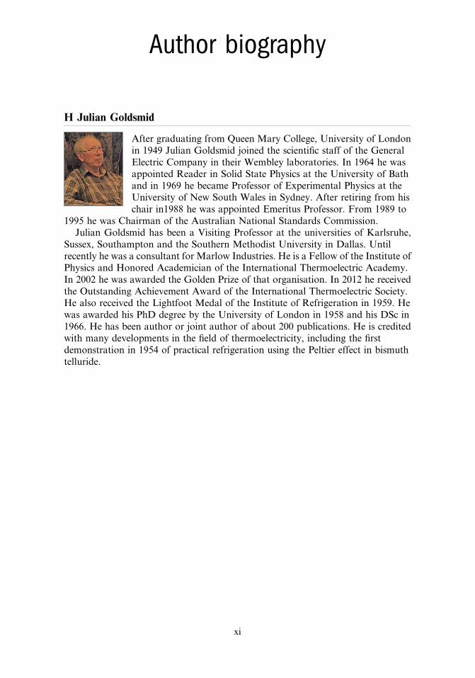
H Julian Goldsmid
After graduating from Queen Mary College, University of Londonin 1949 Julian Goldsmid joined the scientific staff of the GeneralElectric Company in their Wembley laboratories. In 1964 he wasappointed Reader in Solid State Physics at the University of Bathand in 1969 he became Professor of Experimental Physics at theUniversity of New South Wales in Sydney. After retiring from hischair in1988 he was appointed Emeritus Professor. From 1989 to
1995 he was Chairman of the Australian National Standards Commission.Julian Goldsmid has been a Visiting Professor at the universities of Karlsruhe,
Sussex, Southampton and the Southern Methodist University in Dallas. Untilrecently he was a consultant for Marlow Industries. He is a Fellow of the Institute ofPhysics and Honored Academician of the International Thermoelectric Academy.In 2002 he was awarded the Golden Prize of that organisation. In 2012 he receivedthe Outstanding Achievement Award of the International Thermoelectric Society.He also received the Lightfoot Medal of the Institute of Refrigeration in 1959. Hewas awarded his PhD degree by the University of London in 1958 and his DSc in1966. He has been author or joint author of about 200 publications. He is creditedwith many developments in the field of thermoelectricity, including the firstdemonstration in 1954 of practical refrigeration using the Peltier effect in bismuthtelluride.
xi
List of symbols
A Cross-section area, mean atomic weighta Lattice constantB Magnetic fieldC Thermal capacityc Diameter of defectcV Specific heat per unit volumeD* Detectivityd WidthE Electric field, energyEF Fermi energyEg Energy gape Electronic chargeFn Fermi–Dirac integralf Fermi distribution functionf0 Equilibrium Fermi distribution functiong Density of electron statesh Planck’s constantℏ h/2πI Electric currentIϕ Current for maximum COPi Electric current densityj Heat flux densityK Thermal conductanceKc Thermal conductance per unit area of end platesKs Transport integralk Boltzmann’s constantL Length, Lorenz numberle Mean free path of charge carrierslt Mean free path of phononsM (1 + ZTm)
1/2
m Mass of free electronm* Density-of-states effective massmI Inertial massmN Density-of-states mass for a single valleyN Nernst coefficient, total number of modes of vibration, number of unit cell per
unit volume, number of couples in a module, number of stages in cascadeNA Avogadro’s numberNv Number of valleys in an energy bandn Subscript for electronsn Electron concentration, ratio of layer thicknesses in a synthetic transverse
thermoelementP Ettingshausen coefficient, Poisson’s ratiop Subscript for positive holesp Phonon momentumq Rate of heat flow, phonon wave numberQ1 Rate of heat flow from sourceR Electrical resistance, gas constant, responsivity
xii
RH Hall coefficientRL Load resistancer Scattering law parameterS Righi–Leduc coefficients Compatibility factorT TemperatureT1 Temperature of heat sourceT2 Temperature of heat sinkTm Mean temperature, melting pointΔΤ Temperature differenceΔΤ* Temperature difference between sink and sourceΔΤmax Maximum temperature differencet Timeu Velocity of carriersV Voltage, mean atomic volumev Speed of soundw Electrical powerx ℏω/kTZ Thermoelectric figure of merit for coupleZNE Thermomagnetic or Nernst–Ettingshausen figure of meritz Figure of merit for single materialzd Phonon drag figure of meritztrans Transverse figure of meritα Seebeck coefficientαd Phonon drag Seebeck coefficientαT Thermal expansion coefficientβ Chasmar and Stratton’s materials parameter, phase differenceΓ Gamma functionγ Grüneisen’s parameterε Emissivityεm Parameter in melting ruleη Efficiency, reduced Fermi energyηg Reduced energy gapθD Debye temperatureκ Thermal diffusivityλ Thermal conductivityλe Electronic thermal conductivityλI Thermal conductivity of insulationλL Lattice conductivityμ Carrier mobilityν Frequencyξ Reduced energyπ Peltier coefficientπd Phonon drag Peltier coefficientρ Electrical resistivity, densityσ Electrical conductivityτ Thomson coefficient, relaxation timeτ0 Scattering law constantτd Relaxation time for phonon dragτe Relaxation time for charge carriersτeff Effective relaxation time for charge carriers
The Physics of Thermoelectric Energy Conversion
xiii
τN Relaxation time for normal processesτR Relaxation time for umklapp processesϕ Coefficient of performance, angle of transverse thermoelement with normal to
layersϕmax Maximum coefficient of performanceχ Compressibilityω Angular frequencyωD Debye angular frequency
The Physics of Thermoelectric Energy Conversion
xiv
IOP Concise Physics
The Physics of Thermoelectric Energy Conversion
H Julian Goldsmid
Chapter 1
The Seebeck and Peltier effects
1.1 Definition of the thermoelectric coefficientsIn this book we shall review the physical aspects of an energy conversion processthat does not require any mechanical movement. The thermoelectric phenomena inthose solids that conduct electricity are a measure of the energy transported by thecharge carriers. These effects are thermodynamically reversible but they areinvariably accompanied by irreversible effects associated with electrical resistanceand thermal conduction. One of our aims is to show how the reversible processes canbe maximised and the irreversible processes minimised.
The effect that bears his name was discovered in 1821 by Thomas Seebeck. It ismanifest as an electromotive force (EMF) or voltage, V, which appears when thejunction between two dissimilar conductors (A and B) is heated. Strictly speaking,the effect depends on the temperature difference, ΔΤ, between the two junctionsthat are needed to complete the electrical circuit. The Seebeck coefficient isdefined as
=Δ
aVT
. (1.1)AB
Although the effect occurs only when there is a junction between two materials, theSeebeck effect is a characteristic of the bulk rather than surface properties.
The Seebeck effect is often used in the measurement of temperature. Athermocouple for this purpose typically consists of two metals or metallic alloys.For example, copper and constantan, with a differential Seebeck coefficient of about40 μV K−1, are commonly employed. Since a thermocouple measures the temper-ature difference between two junctions, the second junction must be placed in anenclosure at some known temperature, such as a bath of melting ice at 0 °C.
doi:10.1088/978-1-6817-4641-8ch1 1-1 ª Morgan & Claypool Publishers 2017
A closely related effect was discovered in 1834 by Jean Peltier. Peltier heating orcooling occurs when an electric current, I, flows through the junction between twoconductors. The Peltier coefficient, πAB, is defined as
π = qI
, (1.2)AB
where q is the rate of heating or cooling.It is rather more difficult to demonstrate the Peltier effect than the Seebeck effect.
If the thermocouple branches are metallic, the reversible Peltier effect is usuallyovershadowed by irreversible Joule heating. Thus, unless the electric current is verysmall, the best that can be done is to show that the overall heating is less for thecurrent flow in one direction rather than the other. Of course, with the semi-conductor thermoelements that are now available, it is easy to show that water canbe frozen with the current in one direction and boiled with the current in the oppositedirection.
1.2 The Kelvin relationsIt is not surprising that the Seebeck and Peltier coefficients are inter-dependent.Kelvin established two laws that relate αAB and πAB to one another and to a thirdquantity, the Thomson coefficient, τ. The Thomson coefficient is the rate of heatingper unit length when unit current passes along a conductor for unit temperaturegradient. It may be expressed, therefore, as
τ = q xI T xd /dd /d
. (1.3)
Unlike the Peltier and Seebeck effects, the Thomson effect exists for a singleconductor and is present for both branches of a thermocouple.
The relationships between the thermoelectric coefficients can be determined bythe principles of irreversible thermodynamics. These relationships, which are knownas Kelvin’s laws, are
π = a T , (1.4)AB AB
and
τ τ α− = TT
dd
. (1.5)A BAB
It would clearly be helpful if we could assign Seebeck and Peltier coefficients to eachbranch of a thermocouple so that αAB and πAB would be equal to (αA − αB) and(πA − πB) respectively. We note that the thermoelectric coefficients are equal to zerofor all pairs of superconductors, so it is reasonable to suppose that the absolutevalues of α and π are zero for any superconductor. This being so, we can obtainthe absolute values of α and π for any normal conductor by joining it to asuperconductor. Of course, this procedure is effective only below the criticaltemperature of the superconductor. However, the absolute Seebeck coefficient ofthe normal conductor can be extrapolated to higher temperatures [1, 2] using the
The Physics of Thermoelectric Energy Conversion
1-2
second Kelvin relation, equation (1.5). This has actually been done for the metallead, which can be used as a reference material in establishing the absolute Seebeckcoefficients of other conductors.
The first of Kelvin’s laws, equation (1.4), is useful in that it tells us that one doesnot need to specify both the Seebeck and Peltier coefficients. The Peltier coefficientis, in fact, rather difficult to determine, whereas the Seebeck coefficient is one of theeasiest of physical properties to measure. Thus, it is common practice to develop thetheory of thermoelectric energy conversion in terms of the Seebeck coefficient. If andwhen the Peltier coefficient is needed, it is replaced by αT.
1.3 Electrical resistance and thermal conductanceThe Seebeck and Peltier effects are reversible and a thermoelectric energy convertorwould have the characteristics of an ideal heat engine were it not for the presence ofthe irreversible effects of electrical resistance and heat conduction. If one attempts toreduce the Joule heating in a thermocouple by increasing the cross-section area andreducing the length one merely increases the heat conduction losses. In developingthe theory of thermoelectric generation and refrigeration one needs to include termsthat involve the electrical and thermal conductivities of the thermocouple materials.
The electrical conductivity, σ, is defined by the relation
σ = ILVA
, (1.6)
where I is the electric current, V is the applied voltage, L is the length and A is thecross-section area. As we shall see later, it is important to specify that the voltage isthat for isothermal conditions.
The other quantity of interest, the thermal conductivity, λ, is defined by
λ =ΔqL
A T, (1.7)
where q is the heat that is transported for a temperature differenceΔT over a length L.It is obvious that the Seebeck and Peltier coefficients should be as high as possible
and that the electrical conductivity should be large and the thermal conductivitysmall. However, as we shall see later, these requirements cannot all be met in a givenmaterial. Usually an increase in the thermoelectric coefficients is accompanied by adecrease in the electrical conductivity. In the next chapter we shall show the relativeimportance of the different properties and we shall introduce a quantity known asthe figure of merit, z. We shall show how the performance of thermoelectricrefrigerators and generators is related to z.
References[1] Borelius G, Keesom W H, Johansson C H and Linde J O 1932 Proc. Ned. Akad. Wet. 35 10[2] Christian J W, Jan J P, Pearson W B and Templeton I M 1958 Can. J. Phys. 36 627
The Physics of Thermoelectric Energy Conversion
1-3
IOP Concise Physics
The Physics of Thermoelectric Energy Conversion
H Julian Goldsmid
Chapter 2
The thermoelectric figure of merit
2.1 Coefficient of performance of thermoelectric heat pumps andrefrigerators
The possibility of using the Peltier effect as a means of refrigeration was recognisedin the nineteenth century. A refrigerator is a device for transporting heat from asource at a temperature T1 to a sink at a higher temperature T2. The ratio of thecooling power to the rate of working, i.e. the electrical power input, is known as thecoefficient of performance, ϕ. The value of ϕ generally falls as (T2 − T1) increasesand there is a maximum temperature difference, ΔTmax, that can be achieved withany particular heat engine. It is desirable that both ϕ and ΔTmax should be large. Itwas shown by Altenkirch in 1911 [1] that these quantities can be related to theSeebeck coefficient and to the ratio of the electrical to thermal conductivity in eachof the branches of a thermocouple that is used as a refrigerator. Altenkirch’s theoryis still useful though, at the time that it was presented, no thermoelectric materialswere available that allowed worthwhile values of ΔTmax to be reached.
We discuss the performance of a thermoelectric refrigerator using the simplemodel shown in figure 2.1. The diagram shows a single thermocouple situatedbetween a source of heat and a heat sink. The couple will generally consist of apositive and a negative branch though occasionally one of the branches may bea metal with a Seebeck coefficient that is close to zero. For example, a super-conducting branch [2, 3] will not contribute to the thermoelectric effects but neitherwill it impair the performance of the other, active, branch. The branches are usuallylinked by metallic conductors.
When an electric current I flows through the couple there will be a Peltier coolingeffect IπAB, which will be of the order of a tenth of a watt per amp. Most practicalrefrigerators will require several watts of cooling and this is achieved by connectingmany thermocouples thermally in parallel and electrically in series so as to avoid theuse of excessively large currents. However, the theory for a single couple is equallyvalid for a multi-couple arrangement.
doi:10.1088/978-1-6817-4641-8ch2 2-1 ª Morgan & Claypool Publishers 2017
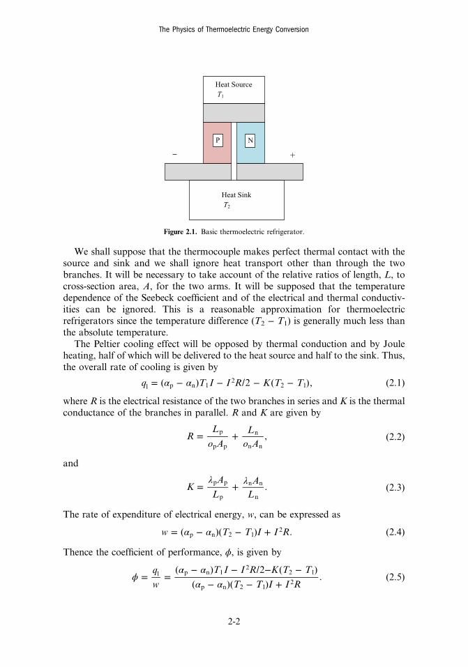
We shall suppose that the thermocouple makes perfect thermal contact with thesource and sink and we shall ignore heat transport other than through the twobranches. It will be necessary to take account of the relative ratios of length, L, tocross-section area, A, for the two arms. It will be supposed that the temperaturedependence of the Seebeck coefficient and of the electrical and thermal conductiv-ities can be ignored. This is a reasonable approximation for thermoelectricrefrigerators since the temperature difference (T2 − T1) is generally much less thanthe absolute temperature.
The Peltier cooling effect will be opposed by thermal conduction and by Jouleheating, half of which will be delivered to the heat source and half to the sink. Thus,the overall rate of cooling is given by
α α= − − − −q T I I R K T T( ) /2 ( ), (2.1)1 p n 12
2 1
where R is the electrical resistance of the two branches in series and K is the thermalconductance of the branches in parallel. R and K are given by
ο ο= +R
L
ALA
, (2.2)p
p p
n
n n
and
λ λ= +KA
LA
L. (2.3)
p p
p
n n
n
The rate of expenditure of electrical energy, w, can be expressed as
α α= − − +w T T I I R( )( ) . (2.4)p n 2 12
Thence the coefficient of performance, ϕ, is given by
ϕα α
α α= =
− − − −− − +
q
w
T I I R K T T
T T I I R
( ) /2 ( )
( )( ). (2.5)1 p n 1
22 1
p n 2 12
Figure 2.1. Basic thermoelectric refrigerator.
The Physics of Thermoelectric Energy Conversion
2-2