the ‘portable’ or ‘base’ 2m/70cm copper-pipe j
TRANSCRIPT

© 2013, N6JSX, Sidney, OH All rights reserved – only nonprofits may copy or print
the ‘PORTABLE’ or ‘Base’ 2m/70cm Copper-pipe "J"
by N6JSX 08/2013 ________________________________________________________________________________________
This is my revised ‘BASE’ 2m/70cm Copper-Pipe “J” a ‘how-to DIY’ with an optional method to make it a ‘PORTABLE’ dual-band “J” for hotel travelers, restricted apartment dwellers, or for limited balcony/patio use. This revision is easier to build while becoming more robust and durable than my previous design. I’m confident you will find this portable ”J” will far exceed any other antenna, in the same setup, more than tripling your 2m & 70cm (440MHz) performance!
Here is my step-by-step to make a portable (or base) ¾” copper-pipe “J” that breaks down into four (~24” long) pieces for easy transporting. This design uses a Bungie-cord to keep all pieces together when unassembled and then insures good element conductivity when assembled. A threaded pipe adaptor was added to the “J” for use with a portable PVC stand or for outside balcony/porch/patio mast mounting. For a rigid robust base “J” omit the Bungie-cord and element items in red.
The original Zepp "J" design dates back to the early 1900’s as an HF antenna hung from the tail of Zeppelin airships. Years later the “J” found its home on VHF/UHF when the following attributes were discovered: requires >NO< ground plane creating a very low angle of radiation, easy and inexpensive to make giving the best value for the effort; has great flatland performance for mobile, marine, or base operations.

© 2013, N6JSX, Sidney, OH All rights reserved – only nonprofits may copy or print
The Technical:
The basic "J" is reported to have >3dB of gain over a ¼λ ground plane antenna and 6dB over an isotropic (theoretical) antenna. The "J" can be made from almost any material: copper pipe, steel whips, TV twin-lead, ladder-line or metal rods. Technically, the "J" antenna is an end-fed ½λ antenna that uses a ¼λ matching stub. Old-timers called it an "end-fed Zepp", bent 90°. In actuality, the conductor is ¾λ long and the matching section uses the bottom ¼λ. The matching stub creates a tuned ½λ length antenna. Due to the matching section acting as the matching transformer, the ½λ radiator sees the lower ¼λ matching section as an image of a false ground plane. In best terms, the "J" is a balanced ¼λ matching stub feeding an unbalanced ½λ load. The feed-lines to a "J" can be almost anything (ladder line to coax). However, in experimentation, I found coax to be best when used at odd ¼ wave multiples in lengths. A “J” is the best for mobile and marine application where you want the most distance across relatively flat ground/water. A 5/8λ or ¼λ antennas have a much higher angle of radiation and must be centered on a ground plane to obtain their optimal radiation patterns, eliminating gutter or vehicle edge mounting. The "J" requires NO additional or special ground plane. A “J” has an exceptionally low, to nearly flat, angle of radiation of near 0-2°. Conversely, the 5/8λ has about 3-6° radiation angle with the highest angle coming from the ¼λ of about 4-10°. These two are usually better suited for higher HAAT (mountain top) repeaters, they both fall way short of a “J” for flat-land distance!
I put a copper-pipe “J” at 65’ on my previous home in Manitowoc, WI. Using 50W I frequently worked repeaters across Lake Michigan or to Milwaukee, Oshkosh, and Upper Michigan that are 60-85 miles away.
NOTE - about dimensions: I’ve read numerous “how-to” build 2m J antenna articles with various dimensions. Everyone has the secret optimal dimension. Over my +40yrs of HAM antenna building every J built has NEVER operated the same as the previously built J. They ‘all’ required some minor tweaking to obtain “optimal” VSWR! However, if you follow the dimensions in this article you will have a J that should exhibit less than 1.5:1 VSWR across the 2m band and under 3.0:1 across 70cm. In my experimentation with the basic J dimensions it was found a long element length of 63.1”
enhances the 70cm band performance {63.1”=2.5λ @ 445MHz}. This longer element length was found to have no adverse affects to the 2m performance.
The Parts BOM: (bill of material) (Lowes 2013)
1 Cu ¾”x10’ pipe type L #23820 $21.00 1 Cu ¾” slip-Tee #21670 $2.70 1 Cu ¾” 90° slip-elbow #21627 $2.88 2 Cu ¾” end-cap #21664 $1.30 2 Cu ¾” slip-coupling w/o stop #22632 $1.92 1 Cu ¾”x¾” threaded male slip-adaptor #21850 $1.50 2 Cu ¾” slip-coupling w/stop #21720 $0.57 1 SO-239 connector (brown Bakelite) $3.00 2 3/8” ID x 7/8” OD washer $0.02 ~3” piece of 3/32” brass brazing rod $0.25 ~7’ ¼” round Bungie-cord $2.75
The ¼” round Bungie (elastic-shock) cord was purchased from an eBay seller. The cord consists of synthetic rubber strands jacketed with a strong, abrasion resistant, braided nylon casing that is mold, mildew, and UV resistant suitable for Marine applications. It can stretch 100% of its original length.
Common plumbers flux & solder and a propane torch 180W solder gun (used to solder the brass rod to the SO-239 center connection)
I use ¾” schedule “L” copper pipe due to experiencing a severely bent ½” copper-pipe J when 59MPH winds hit it. The ¾” pipe is much stronger having withstood multiple >79MPH gusts that bent the Radio-Shack TV mast! Theoretically, the ¾” pipe should exhibit a broader bandwidth than ½” pipe, if present it’s negligible.

© 2013, N6JSX, Sidney, OH All rights reserved – only nonprofits may copy or print
The Build: Basic dimensions for a 146.000 MHz. ¾” copper-pipe “J”
Broken down for transporting, fit-checking

© 2013, N6JSX, Sidney, OH All rights reserved – only nonprofits may copy or print
The Build & Assemble:
Gather your parts and using a pipe cutter it is time to cut pipes; 1. portable long element A pipe = 22.85” 2. portable long element B pipe = 20.0” 3. portable long element C pipe = 20.0” 4. or base long element D (A+B+C=D) pipe = 62.85” 5. match element pipe = 19.20” 6. base pipe = 20.0”
For the base pipe consider your ceiling height plus the 7” stand height. (I use a 20” piece for my base pipe for a total antenna height of ~92”or 7’8”).
Debur and round all pipe edges to insure the Bungie cord will not get cut. Prepare all solder surfaces inside and out, remove all tarnish where soldering will be present to insure a good copper-to-copper joint. Some of my garage stored parts had heavy oxidation/tarnish. Tarn-X™ is a very good product to remove all tarnish/oxidation both inside and out. I put Tarn-X in a wide mouth glass Salsa jar for the bath (I can seal the jar for another project). All soldered parts and pipe ends go into the bath for <10minutes. Remove and wash all the parts with water. All parts are now bight, clean, and ready for soldering. Or you could hand-sand all parts with sand paper for +30 minutes. If you wire wheel (don’t forget the inside solder areas too). Wire wheel is handy but causes surface marring adding extra friction when assembling sliding parts.
The sequence of assembly used here should eliminate frustrating redo’s when you discover a piece was forgotten requiring unsoldering to affix the missing part.
Element A or D: put a liberal amount of plumbers flux on one end of the pipe and slide the T onto this pipe end, then solder to the pipe. Notice how I place the piece into my bench vice using gravity/wicking to help flow the solder into the joint.
Element B: put a liberal amount of plumbers flux on one end of the pipe and slide the slip-coupler w/stop onto the pipe end, then solder to the pipe. Do NOT use much solder as the other side of the coupler will mate to a removable element section.
Element C: put a liberal amount of plumbers flux on one end of the pipe and slide the slip-coupler w/stop onto the pipe end, then solder to the pipe. Do NOT use much solder as the other side of the coupler will mate to a removable element section. The end-cap will be affixed near the end of the assembly process.
Match Element: put a liberal amount of plumbers flux on one end of the pipe and slide the 90° slip-elbow onto the pipe end, then solder to the pipe.
Element A / D Match Element

© 2013, N6JSX, Sidney, OH All rights reserved – only nonprofits may copy or print
Element B Element B (soldered)
Base pipe thread adaptor: place the washer inside the adaptor as seen in BP-1. BP-2 & BP-3 are shown to give you a perspective of the Bungie cord placement inside the long J elements. Put a liberal amount of plumbers flux on the base pipe end and slip the adaptor onto the pipe trapping the washer, then solder.
BP-1 BP-2 BP-3
¾” pipe threaded mating adaptors
NOTE: a threaded mating adaptor can be used with another ¾” pipe or threaded PVC adaptor to make a simple outdoor mast mount or used with The “J” Stand.

© 2013, N6JSX, Sidney, OH All rights reserved – only nonprofits may copy or print
J-joint: now for a critical solder joint - the T to the 90° slip-elbow (matching element). I did a layout ‘J Fit-Check’ prior to soldering to insure all pieces aligned properly. The matching element needs to be placed so it is perfectly parallel to Element A / D longer element, ‘J soldering setup’. Put a liberal amount of plumbers flux on the 90° slip-elbow and slide into the T center, align the two elements and solder. (Reflow/reheat the solder if the matching element requires alignment tweaking.)
J Fit-Check J soldering setup
Base pipe: put a liberal amount of plumbers flux on the base pipe end and slide into the bottom of the T, then solder the pipe, BP-4. For the “Portable” J do ‘NOT’ solder base pipe to the T.
BP-4
Jump to “The Feed-point “process in this article, then return here and continue building.
Match element cap: put a liberal amount of plumbers flux on the matching pipe end and slide the cap into place, BC-2, then solder the pipe.

© 2013, N6JSX, Sidney, OH All rights reserved – only nonprofits may copy or print
Bungie Cord: 1. The J long element pieces are ~65”, add the length of the base mounting pipe w/adaptor for a total
length of XX”. Add ~8” to the XX” for the length of cord to cut, YY. Cut the ¼” Bungie cord to YY length. 2. Place a loose knot on one far end of the cord. 3. String the cord starting from the adaptor mount threading the Bungie cord thru the washer hole. 4. Thread the cord thru the element pipes assembled in proper order until the cord comes out the top. 5. Thread the cord thru the loose washer, as seen in BC-1, put a tight knot in the top cord. 6. Using liquid super glue soak the knot and let dry, closely trim excess cord at the knot. 7. Put a liberal amount of plumbers flux on Element C pipe-end, slide the end-cap over the knot/washer,
BC-2, then solder the pipe. The cap will be a knot higher creating that 0.25” dimension making the “J” the full 63.1” in over all length from the Tee-90° elbow.
BC-1 BC-2 BC-3
Bungie cord tension adjustment: this becomes a personal preference setting as to how much tension you feel the Bungie cord needs to have to keep good element connections. Remember, when you pull the elements apart the tension/length will grow ~2-4”, over stretching the cord will shorten the cords life span. This marine Bungie cord is very robust so I pulled ~18” of cord and put a figure 8-knot at the adaptor washer end. Trim off the excess cord leaving ~1” tail to grab as seen in BC-3.
The J can now be pulled apart for storage/transporting and not loose any pieces, BC-4 & BC-5.
BC-4 BC-5 Element D: put a liberal amount of plumbers flux on Element D pipe end, slide the end-cap over the pipe to measure 63.1” from the Tee-90° elbow, then solder, BC-2.
© 2013, N6JSX, Sidney, OH All rights reserved – only nonprofits may copy or print
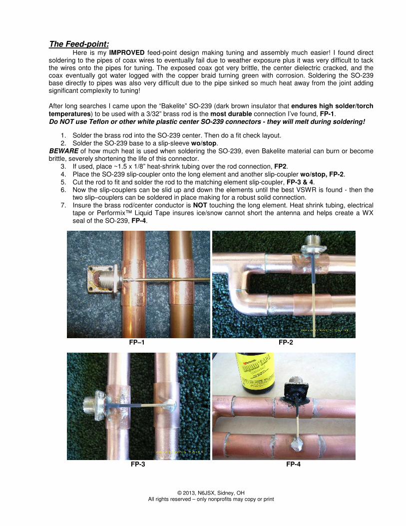
The Feed-point: Here is my IMPROVED feed-point design making tuning and assembly much easier! I found direct soldering to the pipes of coax wires to eventually fail due to weather exposure plus it was very difficult to tack the wires onto the pipes for tuning. The exposed coax got very brittle, the center dielectric cracked, and the coax eventually got water logged with the copper braid turning green with corrosion. Soldering the SO-239 base directly to pipes was also very difficult due to the pipe sinked so much heat away from the joint adding significant complexity to tuning! After long searches I came upon the “Bakelite” SO-239 (dark brown insulator that endures high solder/torch temperatures) to be used with a 3/32” brass rod is the most durable connection I’ve found, FP-1. Do NOT use Teflon or other white plastic center SO-239 connectors - they will melt during soldering!
1. Solder the brass rod into the SO-239 center. Then do a fit check layout. 2. Solder the SO-239 base to a slip-sleeve wo/stop.
BEWARE of how much heat is used when soldering the SO-239, even Bakelite material can burn or become brittle, severely shortening the life of this connector.
3. If used, place ~1.5 x 1/8” heat-shrink tubing over the rod connection, FP2. 4. Place the SO-239 slip-coupler onto the long element and another slip-coupler wo/stop, FP-2. 5. Cut the rod to fit and solder the rod to the matching element slip-coupler, FP-3 & 4. 6. Now the slip-couplers can be slid up and down the elements until the best VSWR is found - then the
two slip–couplers can be soldered in place making for a robust solid connection. 7. Insure the brass rod/center conductor is NOT touching the long element. Heat shrink tubing, electrical
tape or Performix™ Liquid Tape insures ice/snow cannot short the antenna and helps create a WX seal of the SO-239, FP-4.
FP–1 FP-2
FP-3 FP-4

© 2013, N6JSX, Sidney, OH All rights reserved – only nonprofits may copy or print
The “J” Performance:
2m VSWR
1.0
1.5
2.0
2.5
3.0
144.0144.5
145.0145.5
146.0146.5
147.0147.5
148.0149.0
150.0155.0
70cm VSWR
1.0
1.5
2.0
2.5
3.0
420
425
430
435
440
441
442
443
444
445
446
447
448
449
450
455
460
465
470
Tuning: place the J antenna >20’ from all buildings/structures. I use a 3’ wood ladder as my antenna tuning platform (that doubles as my portable SAT Comm stand as seen in http://groups.yahoo.com/group/HAM-SATs/photos/album/855859257/pic/list ). I made a simple PVC mast for the threaded J base.
When connecting >1.25λ @ 2m coax between the MFJ-269 to the J SO-239, the couplers slid down the elements. I used a small piece of electrical tape to hold the couplers in place while conducting measurements. Set the MFJ at 146.000 and slide the couplers up & down to find the best VSWR; measure this dimension. My best VSWR was when the brass rod is 3.45” from the top of the 90°/T connection. Graphed data shows the measured VSWR at this tap point.
Apply liberal coat of plumbers flux to the elements and place the couplers at your measured VSWR dimension, heat the element pipes above/below the couplers using wicking to draw the solder into the coupler joint. It does not take much solder or heat for a good joint - too much heat may compromise the SO-239 taps.
Now enjoy your new J antenna you earned it!

© 2013, N6JSX, Sidney, OH All rights reserved – only nonprofits may copy or print
The “J” Stand:
This is a ¾” Sch-40 PVC stand using Lowes ¾” threaded slip-joint “Tee” (#23934 $0.96ea). The Lowes ¾” 90-degree side outlet elbow (#315496 $1.60ea) makes this four-leg stand easy to assemble and very stable. All legs are ¾”x 6” with end-cap feet and the two T-arms are ¾”x 4.5” giving the stand a foot print of 13.5”x11”. The strategic assembly part of making this stand is insuring the “T” remains perpendicular to the ground during the gluing while making ‘all’ feet share the load equally to make a balance stand. I made this stand into three portable pieces: two legs and a T-arm, see JS-parts. I drilled a hole thru the T-arm/elbow joints for a drop-in pin (cotter-key or nail). This pin will negate any T-arm rotation keeping the J perpendicular to the floor. The copper J-base adaptor screws into the PVC T for a solid fit. This foot-print also keeps the J from making direct contact with walls improving the J performance. I spray painted my stand, brown, just to make it unobtrusive in the room but the color is purely a personal preference.
JS-parts

© 2013, N6JSX, Sidney, OH All rights reserved – only nonprofits may copy or print
Other worthy ‘J’ tid-bits:
I have found that the length of the attached coax can have an affect on the J’s VSWR. Multiples of odd ¼λ lengths minimize these coaxial affects. I have pruned off 3” pieces of coax in the HAM shack to bring the VSWR back to 1:1 original tuning of the antenna. On VHF/UHF the VSWR variances are very susceptible to the consistency of the coax velocity factor, aka quality. I experimented using Bazooka-Balun (2m & 70cm RF chokes) and found no VSWR difference or benefit when adding these chokes to the coax feed. The "J" offers the foundation for a stealth antenna by placing the J inside 2”/3”/4” PVC with an angled mounting box making it appear to be a roof gas/sewer-breather pipe on CCR restricted houses. Note 1. The TV twin lead “J” is the “BEST” hidden transmitter hiding antenna I’ve ever used. It can be wrapped around branches of a tree, tossed up into a tree, or laid on top tall riverbank grass causing it to emit complex angles of various polarizations that cause extremely deceptive multi-path. I’ve put a TV twin-lead “J” inside PVC, making it H2O proof, burying it adjacent and parallel to the bottom wire of a cattle range fence. The wire fence running miles through the Puente Hills; parasitically re-radiating the 2W signal for long distances in both directions, add to this the limited access to the area and the hunters were totally confused for many many hours. This same PVC-J was put onto a creek bottom under 12” of flowing water – that was fun to watch hunters begrudgingly wading into cold waste deep creek water. Note 1. I take a wire wheel, steel wool, Emery cloth, Tarn-X to make my copper “J” shine. Then I put multiple coats of Varithane/Polyurethane (outdoor anti-UV type Clear) over the entire antenna - this retains the antennas luster, brightness, and keeps it tarnish free for years.
(Note 1: PVC/ABS will detune an open air tuned J due near field interference – retuning is required.)
Other "J" antenna designs published in 73 Magazine have been; Copper Cactus (2m) J-Pole by KE7AX, February, 1992.
The J Antenna by N6JSX, August, 1996. 220 Super J-Pole Antenna by KA0NAN, May 1996. 440 Super J-Pole Antenna by KA0NAN, April 1996. Simple J-Type 10m Vertical by W6IOJ, Sept. 1995.
A 146 & 445 MHz J-Pole by W4ULD, ARRL QST Oct, 2000 the SIMPLE 2m Copper-pipe “J” by N6JSX, March, 2001, eHAM.Net & Hamuniverse.com the CB-whip HAM “J” by N6JSX, June 2012, eHam.Net & Hamuniverse.com
Writer BIO: Dale Kubichek, BS/MS-EET, GROL/RADAR, N6JSX - Amateur Extra; licensed in 1972. Served 10yrs USN, Vietnam Vet, FTG1 Gun/Missile systems & electronics instructor. Electronics Test/MFG/QA Engineer & Program Manager, aerospace - Hughes, Northrop, Rockwell, HawkerBeechcraft; commercial - Magellan, Mitsubishi, Emerson-Copeland; heavy construction - TEREX, Manitowoc Cranes, Magnetek; communications – Hughes, STM, RockwellCollins. Currently, USAF UAS/UAV SIMs Program-Office Sr. Engineer. Interests are in designing/testing antennas, RDF hunting/training, SAT Ops - AMSAT FOX Design Team member; published numerous articles 73 Magazine, WI Badger Smoke Signals, eHAM.net & HamUniverse.com. A PDF of this article, and many more, can be found in the ‘Files’ folder “N6JSX Stuff” on my Groups: http://groups.yahoo.com/group/HAM-SATs http://groups.yahoo.com/group/RDF-USA