the potential of freeform construction …edge.rit.edu/edge/p10551/public/sff/sff 2005...
TRANSCRIPT

THE POTENTIAL OF FREEFORM CONSTRUCTION PROCESSES R. A. Buswell1, R. Soar1, A. Gibb2, A..Thorpe2
1 – Wolfson School of Mechanical and Manufacturing Engineering; 2 – Civil and Building Engineering;
Loughborough University, Leicestershire, LE11 3TU. Reviewed, accepted September 7, 2005
Abstract The level of automation technology and processes control found in modern day construction lags significantly behind other industries such as automotive and aerospace. The construction industry has health and safety issues and still uses traditional methods of procurement. These problems are compounded by diminishing skills in the labour force. Methods of production must change if these issues are to be resolved and Freeform Construction is a collection of processes that could have potential impact. This paper outlines some of the major issues facing construction and sets a context with examples of digital fabrication in construction. Freeform Construction is defined and potential applications are presented and related to application scale. The viability of two potential applications are investigated in terms of cost.
Introduction Developments in the construction industry are decades behind other industries such as, aerospace, automotive and ship building. These have advanced considerably in terms of computer aided design processes, systems modelling and automated assembly. So, why hasn't construction?
Construction has a number of problems. It hasn’t changed for hundreds of years: The Romans invented concrete about 100BC and 2200 years later we are still using it as a primary build material. It has an image problem; people relate construction with poor performance and quality, poor cost and time (Latham 1994). Technologies are limiting imagination; new methods of production and assembly often result in moving the 'hand trades' away from the construction site rather than developing new processes (Gibb, Pendlebury 2003). Competition for projects concentrate on first cost; the cheapest bid wins and there is little time, money or energy to invest in innovation. The industry is also conservative and any innovations tend to be incremental changes. Where changes and improvements are made, the transient nature of the work and workforce often means that these improvements are not adopted on new projects as they might in a manufacturing environment. There is a growing problem relating to skills and although operative safety is improving, construction is still a hazardous environment (Egan 1998). In addition, the industry is likely to face increasing pressures from developing environmental issues (Guthrie et al. 1999). There is a need for more radically different solutions. As human endeavour pushes further forward, construction will need to be able to respond to unique challenges in aggressive environments such as the North pole, desert, chemical contamination and off-world.
Process automation offers a large departure from conventional methods of construction. This has largely been investigated in terms of robotics (Gambao, Balaguer & Gebhart 2000, Kahane, Rosenfield 2004, Kuntse et al. 1995, Lorenc, Handlon & Bernold 2000, Stein, Gotts & Lahidji , Werner 1995, Williams, Albus & Bostelman 2004). Large scale 'factory' approaches have been demonstrated by the construction of the Shimizu Corporation building (Yamazaki, Maeda 1998).
Several articles in the recent construction press have considered more radical solutions. (Sweet 2003) talks about the use of nanobots for construction. (Lane 2004) talks to Berokh Khoshnevis about off-world construction and (Buswell, Soar 2005) discuss the possibilities for Freeform Construction. This paper continues the discussion of applications for Freeform Construction.
503

Digital Fabrication in Construction
Rapid Prototyping has been used in the construction arena, but has been largely restricted to concept modelling in architecture (Kalay, Skibniewski 2002), or plant development (Melling et al. 1997). Pegna considered a layer deposition method suitable for traditional construction materials (Pegna 1997). Contour Crafting has been demonstrated to have the potential for generating full scale structures directly from digital data (Khoshnevis 2002).
In recent years there have been a significant number of buildings constructed using large scale manufacturing methods. Construction, like manufacturing, uses CAD. Typically in construction, however, its use is limited to the coordination and production of the design drawings and associated information. However, a number of Architects are taking digital models and using them directly in the production of major building components. In addition, vendors such as Bentley Systems are developing new types of design software to bridge between the conceptual architectural design to digital fabrication. The ability to use 3D solid CAD models, with computer based analysis tool is generating impressive freeform architecture. The application of CNC milling to generate large scale moulds and sheet cutting methods to generate the structural components makes these projects realisable in terms of feasibility and cost (Kolarevic 2005).
Frank Gehry’s Zollhoff Towers in Dusseldorf: Modelled in CATIA, the Zollhoff
Towers are an example where CNC cutting and milling were employed to generate the structure of buildings. The towers are three blocks of offices, each made up of a series of 'twisted' and 'warped' rises in which every wall panel is curved. One set of offices is finished in metal, one painted and one in brickwork. Plasma-arc CNC cutting of sheet steel was used to form the masonry supports. The load bearing, curved, external wall panels were produced using blocks of lightweight polystyrene and CNC milled to produce 355 different curved molds that became the forms for the casting of the concrete.
Bernhard Franken, 'The Bubble': The BMW pavilion for the 1999 motor show was
designed by Bernhard Franken. The space frame was cut from aluminum and the double curved, acrylic glass panels were formed using polystyrene moulds created using multi-axis milling. The actual form of the structure, however, was defined by a computer simulation of two water droplets merging, an example of the integration of design allowing engineering to contribute directly to architectural form.
www.arcspace.com
Bernard Cache, Objectile: Objectile is a Paris based company that combines engineering,
mathematics, technology, and philosophy to work on the industrial design and manufacturing of curved and variable forms of every proportion, including sculpture, design, furniture, building components, architecture, town planning or landscaping. Objectile has developed their own software for controlling multi-axis milling tools.
Kevin Rotheroe, Freeform Tubes: Freeform Tubes developed by Rotheroe are interlocking, freeform structural steel members. The component mould patterns are manufactured
using CNC milling. The parts are then cast in steel.
Today Construction is using CAD/CAM to liberate architectural possibilities. We can control the shape of construction components directly from the digital design model. These can be manufactured through automated processes and assembled on site. The next technological step is to control the deposition of the construction material directly from the building model.
504
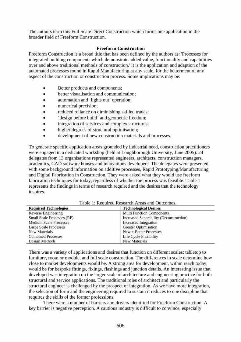
The authors term this Full Scale Direct Construction which forms one application in the broader field of Freeform Construction.
Freeform Construction
Freeform Construction is a broad title that has been defined by the authors as: 'Processes for integrated building components which demonstrate added value, functionality and capabilities over and above traditional methods of construction.' It is the application and adaption of the automated processes found in Rapid Manufacturing at any scale, for the betterment of any aspect of the construction or construction process. Some implications may be:
• Better products and components; • better visualisation and communication; • automation and ‘lights out’ operation; • numerical precision; • reduced reliance on diminishing skilled trades; • ‘design before build’ and geometric freedom; • integration of services and complex structures; • higher degrees of structural optimisation; • development of new construction materials and processes.
To generate specific application areas grounded by industrial need, construction practitioners were engaged in a dedicated workshop (held at Loughborough University, June 2005). 24 delegates from 13 organisations represented engineers, architects, construction managers, academics, CAD software houses and innovations developers. The delegates were presented with some background information on additive processes, Rapid Prototyping/Manufacturing and Digital Fabrication in Construction. They were asked what they would use freeform fabrication techniques for today, regardless of whether the process was feasible. Table 1 represents the findings in terms of research required and the desires that the technology inspires.
Table 1: Required Research Areas and Outcomes.
Required Technologies Technological Desires Reverse Engineering Multi Function Components Small Scale Processes (RP) Increased Separability (Deconstruction) Medium Scale Processes Increased Integration Large Scale Processes Greater Optimisation New Materials New + Better Processes Combined Processes Life Cycle Flexibility Design Methods New Materials There was a variety of applications and desires that function on different scales; tabletop to furniture, room or module, and full scale construction. The differences in scale determine how close to market developments would be. A strong area for development, within reach today, would be for bespoke fittings, fixings, flashings and junction details. An interesting issue that developed was integration on the larger scale of architecture and engineering practice for both structural and service applications. The traditional roles of architect and particularly the structural engineer is challenged by the prospect of integration. As we have more integration, the selection of form and the engineering required to sustain it reduces to one discipline that requires the skills of the former professions.
There were a number of barriers and drivers identified for Freeform Construction. A key barrier is negative perception. A cautious industry is difficult to convince, especially
505

0
50
100
150
200
250
300
1 2
Case Number (-)
Cos
t (E
uro/
m2)
3D Printing cost per unit: at one tenth material cost
3D Printing cost per unit
Figure 1: Comparison of Retail Prices for Plaster Ceiling Roses.
when talking about processes that are so removed from traditional methods. Contractual obligations was a further issue. Greater integration of function may require new definitions for the responsibility for the design. And with the digital design model controlling construction, is the designer also responsible for the build process? Finding clients willing to support radical changes was also identified as important.
There were strong drivers for the development of technology. Control of the construction environment was important as were the perceived benefits of increasing the control of material deposition and involving more optimisation. A strong case was for the realisation of complex forms at any scale. Some application possibilities were identified. An extension of visualisation, was the use of models of problematic sections of the construction and hence heightened communication between the designers and construction teams.
Cost and Time Examples of two applications identified above are considered here. The first case compares the cost of producing ceiling roses by 3D printing to the retail cost of products at the mass produced and specialist ends of the market. The second compares the cost of producing a wall using a hypothetical, scaled up, 3D printing machine against using traditional construction methods. Ceiling Rose Analysis A mass produced and a highly ornate, specialist ceiling rose costing 22 Euros and 263 Euros respectively were selected, both approximately ~350mm diameter (Anon. 2004a, Anon. 2004b). The analysis is based on that given in (Hopkinson, Dickens 2003). The machine capital and maintenance costs are for the ZCorporation 810 gypsum based process and are taken from (Wohlers 2004). Full details of the analysis can be found in (Buswell, Soar 2005). Figure 1 shows the comparison of the costs assuming an overhead, profit and retail mark-up of 40%. The 3D printed product cost would be 231 Euros. The plaster and binder costs would need to be reduced to a tenth of the current price for the resultant part retail cost to be competitive at the mass produced end of the market (34 Euros). The material cost is significant in determining the final part cost. At current material prices, the 3D-printed product cannot compete with mass production, but it can at the specialist end of the market. The added value allowed in the 3D process, such as each rose in a build could
506

Figure 2: Typical UK cavity wall construction. be unique, are not quantified here and strengthen the case. In addition, the examples here used utilise ready made moulds. A product requiring a custom made mould would cost a great deal more, increasing the viability of the 3D printed product. Wall Construction Example In the UK, a traditional wall might comprise: 13mm of internal plaster finish on a 100mm concrete block with a 50mm cavity and 100mm external facing brick, neglecting fixings, insulation, etc. Figure 2 shows an example. The cost comparison considers the construction of such a wall 5m long by 3m high, using traditional labour and using a hypothetical scaled up version of the ZCorporation 810 machine to produce an equivalent. The Zcorp wall was assumed to produce a finished wall with no additional post processing requirement. The material was assumed to be fit for purpose. The machine costs were based on a linear scaling of the current relationship between product build volume and cost. The material volumes of the ZCorp 'brick' and 'block' leaves are assumed to be 50% of the overall volume. The traditional construction costs and times were estimated using Spon’s guide (Anon. 2002a, Anon. 2002b). The 3D printing process data was sourced as for the previous example. Table 2 details the linearly extrapolated cost data associated with the scaling up of the 810 machine. Table 3 gives the cost analysis breakdown for the production of the wall using 3D printing at the current market material cost for raw gypsum (courtesy of BPB plc). Table 4 details the cost breakdown for the traditional construction for two cases. The first is the cost of building a plain wall. The second gives the cost of building in multiple electrical conduits, which might be found in a commercial kitchen application. Figure 3 depicts the calculated data. It is assumed that the serviced wall can be produced by the 3D printing process with no cost or time penalty.
Table 2: ZCorp Machine Cost Estimate Data. Machine Build Volume (m3) Cost (Euros) Capital Cost
406 0.01 42765 810 0.12 136241 Example machine (Capital Cost = 849782 * Build Vol. + 34267) 3.75 3220950 Maintenance Cost
406 0.01 5680 810 0.12 14390 Example machine ( Cost = 79182 * Build Vol. + 4888 ) 3.75 301821
507

Table 3: Cost Analysis for Plaster Wall Production Using 3D Printing. Part Name Data Units Build data
Number per platform 1 - Platform build time (43mm/hour) 70 hours Production rate per hour 1 part/hour Hours per year in operation (90%) 7884 hours Production area total per year 118260 m2
Machine Costs
Machine & Ancillary Equipment 3220950 Euro Equipment Depreciation Cost/year 402619 Euro Machine maintenance cost per year 301821 Euro Total machine cost per year 704440 Euro Machine cost per m2 of wall 5.96 Euro/m2
Labour Costs
Machine operator cost per hour 7.07 Euro Time to control machine (1man for all run time) 7884 Hours/year Labour costs per m2 of wall 0.47 Euro/m2
Materials costs
Volume of material per m2 of wall (assume 50% by volume) 0.1 m3/ m2
Processed build material cost per tonne 86 Euro/tonne Processed build material cost ( density of 1600kg/m3) 140 Euro/m3
Processed build material cost of transport and profit (40%) 56 Euro/m3
Build material with binding agent (x2 raw material cost) 392 Euro/m3
Binder cost per unit volume (twice build material cost) 784 Euro/m3
Cost of material per m2 of wall 39 Euro/m2
Cost of binder per m2 of wall (30% material volume) 26 Euro/m2
Material cost per m2 of wall 65 Euro/m2
Total cost per m2 of wall 71 Euro/m2
Table 4: Cost Analysis for Traditional Plastered Wall Production.
Part Name Data Units Plant Costs
Fork lift 6.86 Euro/hr Hours in attendance for whole wall (3 days x 1 hrs per day) 21 Euro Scaffold (mobile) 2.86 Euro/hr Hours in attendance for whole wall (3 towers for 2 days-8hr) 137 Euro Plant cost per m2 of wall 10.50 Euro/m2
Labour Costs (1 form, 6 brick, 4 lab)
100mm facing brick 25.50 Euro/m2
100mm internal block 11.50 Euro/m2
Plaster 13.08 Euro/m2
Labour costs per m2 of wall 50.08 Euro/m2
Materials costs
100mm facing brick 19.03 Euro/m2
100mm internal block 11.50 Euro/m2
Plaster 2.34 Euro/m2
Material cost per m2 of wall 32.87 Euro/m2
Total cost per m2 of wall 93 Euro/m2
508

Table 5: Cost Analysis for Heavily Serviced, Traditional Plastered Wall Production. Part Name Data Units Plant Costs
Fork lift 6.86 Euro/hr Hours in attendance for whole wall (3 days x 1 hrs per day) 21 Euro Scaffold (mobile) 2.86 Euro/hr Hours in attendance for whole wall (3 towers for 3 days-8hr) 206 Euro Plant cost per m2 of wall 15.13 Euro/m2
Labour Costs (1 form, 6 brick, 4 lab)
100mm facing brick 25.50 Euro/m2
100mm internal block 11.50 Euro/m2
Chasing (5 full height runs – 25m, 1day for labourer) 3.13 Euro/m Conduit (5 full height runs – 25m) 9.63 Euro/m Switch boxes (2 per run – 10#) 17.10 Euro/each Plaster 13.08 Euro/m2
Labour costs per m2 of wall 82.75 Euro/m2
Materials costs
100mm facing brick 19.03 Euro/m2
100mm internal block 11.50 Euro/m2
Conduit (5 full height runs – 25m) 5.55 Euro/m Switch boxes (2 per run – 10#) 4.42 Euro/each Plaster 2.34 Euro/m2
Material cost per m2 of wall 45.07 Euro/m2
Total cost per m2 of wall 143 Euro/m2
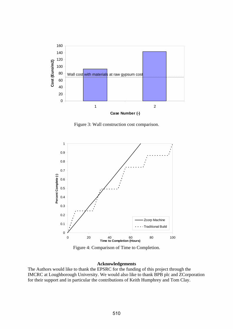
In Figure 3, Case 1 shows the plain wall cost and Case 2 gives the serviced wall cost. The production of the wall using current 3D printing materials is prohibitively expensive. Figure 3 shows that the material cost would have to be close to that of raw gypsum to be economically viable. The figure does demonstrate, however, that the case for highly serviced walls (a degree of systems integration, or increased functionality) does improve the cost argument. In terms of wall build time to completion, Figure 4 compares the traditional process with the constant build rate of 43mm/hr associated with the 810 machine. The steps in the traditional methods come from having to leave every ~1m height in brickwork overnight for the mortar to set (maximum weight on wet mortar). The highly serviced wall characteristic is similar but exacerbated because of the curing of mortar before chasing the wall that has to be then fitted with conduit before is can be plastered. Excepting that it was assumed that there was no operational efficiency in the labour allocation (continuous work) and neglecting the set up time for the machine, the 3D printing is comparable in build time to traditional methods.
Conclusions The state of the construction industry in terms of the application of digitally controlled fabrication techniques has been described. Freeform Construction has been defined and the build scales relating to various freeform process applications within construction has been given. Feedback from a section of the UK industry defined some board areas for research potential and some desires that technology should deliver. Two construction related cases based on cost were considered. For the production of 'small' specialist plaster components, using the Z Corporation 810 machine can be cost effective as a manufacturing device. For the production of large scale construction components such as walls, the current material cost is prohibitively expensive. If the build material cost can be brought closer to the cost of raw gypsum, however, the process becomes viable in terms of cost and build time to completion.
509
0
20
40
60
80
100
120
140
160
1 2
Case Number (-)
Cost
(Eur
o/m
2)
Wall cost with materials at raw gypsum cost
Figure 3: Wall construction cost comparison.
0
0.1
0.2
0.3
0.4
0.5
0.6
0.7
0.8
0.9
1
0 20 40 60 80 100Time to Completion (Hours)
Perc
ent C
ompl
ete
(-)
Zcorp Machine
Traditional Build
Figure 4: Comparison of Time to Completion.
Acknowledgements The Authors would like to thank the EPSRC for the funding of this project through the IMCRC at Loughborough University. We would also like to thank BPB plc and ZCorporation for their support and in particular the contributions of Keith Humphrey and Tom Clay.
510

References
Anon. 2004a, , Berry: C&W Berry Ltd. Available: http://www.cwberry.com [2004, 12/18] .
Anon. 2004b, , The Regency Town House. Available: http://www.regency-town-house.org.uk [2004, 12/18] .
Anon. 2002a, Spons Architects & Builders Price Book, Spon Press, London.
Anon. 2002b, Spons M & E Services Price Book, Spon Press, London.
Buswell, R.A. & Soar, R.C. 2005, "The Future of Construction?", Public Service Review: Construction, , no. 3, pp. 87-88.
Egan, J. 1998, Rethinking Construction, Department of the Environment, London.
Gambao, E., Balaguer, C. & Gebhart, F. 2000, "Robot Assembley System for Computer-integrated Construction", Automation in Construction, vol. 9, pp. 479-487.
Gibb, A. & Pendlebury, M. 2003, Standardisation and Pre-Assembly Project Tool Kit, CIRIA, London.
Guthrie, P., Coventry, S., Woolveridge, C., Hillier, S. & Collins, R. 1999, The reclaimed and recycled construction materials handbook CIRIA, London.
Hopkinson, N. & Dickens, P. 2003, "Analysis of rapid manufacturing - Using layer manufacturing processes for production", Proceedings of the Institution of Mechanical Engineers, Part C: Journal of Mechanical Engineering Science, vol. 217, no. 1, pp. 31-40.
Kahane, B. & Rosenfield, Y. 2004, "Real-Time Sense-and-Act Operation for Construction Robots", Automation in Construction, vol. 13, no. 6, pp. 751-764.
Kalay, Y.E. & Skibniewski, M.J. 2002, "Special Issue: Rapid Prototyping", Automation in Construction, vol. 11, no. 3.
Khoshnevis, B. 2002, "Automated Construction by Contour Crafting – Related Robotics and Information Sciences", Automation in Construction Special Issue: The best of ISARC 2002, vol. 13, no. 1, pp. 2-9.
Kolarevic, B. 2005, "Digital Praxis: From Digital to Material", 3rd International Conference on Innovation in Architecture, Engineering and Construction (AEC), eds. S. Sariyildiz & B. Tuncer, Delft University, Rotterdam, pp. 5.
Kuntse, H.B., Hirsch, U., Jacubasch, A., Eberle, F. & Goller, B. 1995, "On the dynamic control of a hydraulic large range robot for construction applications", Automation in Construction, vol. 4, pp. 61-73.
Lane, T. 2004, "A Giant Leap for a Brickie", Building Magazine, , no. 28, pp. 39-42.
Latham, M. 1994, Constructing the Team, HMSO, London.
511
Lorenc, S.J., Handlon, B.E. & Bernold, L.E. 2000, "Development of a robotic bridge maintenance system", Automation in Construction, vol. 9, pp. 251-258.
Melling, G., Bradley, D.A., McKee, H. & Widden, W.B. 1997, The Development of a Rapid-Prototyping Technique for Mechatronic-Augmented Heavy Plant.
Pegna, j. 1997, "Exploratory investigation of solid freeform construction", Automation in Construction, vol. 5, no. 5, pp. 427-437.
Stein, J., Gotts, V. & Lahidji, B. Construction Robotics.
Sweet, R. 2003, "Buildings that Build Themselves", Construction Manager, , no. October, pp. 14-17.
Werner, L. 1995, "Experiences with the Construction of a Building Assembly Robot", Automation in Construction, vol. 4, pp. 45-60.
Williams, R.L., Albus, J.S. & Bostelman, R.V. 2004, "Self-Contained Automated Construction Deposition System", Automation in Construction, vol. 13, pp. 393-407.
Wohlers, T. 2004, Rapid Prototyping, Tooling & Manufacturing: State of the Industry, Wohlers Associates, Colorado, USA.
Yamazaki, Y. & Maeda, J. 1998, "The SMART system: an integrated application of automation and information technology in production process.", Computers in Industry, vol. 35, pp. 87-99.
512