(the “property”) at&t mobility (“at&t”
TRANSCRIPT

Empire Telecom USA, LLC • 16 Esquire Road, Billerica, MA 01862 • 978-935-6913 • [email protected]
March 15, 2019
Melanie A. Bachman
Executive Director
Connecticut Siting Council
10 Franklin Square
New Britain, CT 06051
Regarding: Notice of Exempt Modification – Antenna Modification
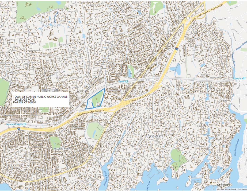
Property Address: 126 Ledge Road; Darien, CT 06820 (the “Property”)
Applicant: AT&T Mobility (“AT&T”), Site # CT2104
Dear Ms. Bachman:
AT&T currently maintains a wireless telecommunications facility on an existing 117-foot
monopole at the above-referenced address, latitude 41.07244167°, longitude -73.47815000°. Said
monopole is owned by Crown Castle and the underlying property owner is the Town of Darien.
AT&T desires to modify its existing telecommunications facility by adding (3) Remote Radios
(RRUs). The centerline height of the existing antennas and ancillary tower-mounted equipment is and
will remain at 89 feet.
Please accept this application as notification pursuant to R.C.S.A. §16-50j-73, for construction
that constitutes an exempt modification pursuant to R.C.S.A. §16-50j-72 (b)(2). In accordance with
R.C.S.A. §16-50j-73, a copy of this letter is being sent to the Jayme Stevenson, First Selectman of
Darien; Jeremy Ginsberg, as Planning and Zoning Director of the Town of Darien; the Town of Darien
having received notice to the First Selectman, as property owner; and the tower owner, Crown Castle.
The planned modifications to AT&T’s facility fall squarely within those activities explicitly
provided for in R.C.S.A. §16-50j-72 (b)(2). Specifically:
1. The planned modification will not result in an increase in the height of the existing structure.
The added equipment will be installed at the existing height of 89 feet on the 117-foot
monopole.
2. The proposed modifications will not involve any changes to AT&T’s ground-space footprint,
and therefore and therefore will not require an extension of the site boundary.
3. The proposed modification will not increase the noise level at the facility by six decibels or
more, or to levels that exceed state and local criteria.
4. The operation of the modified facility will not increase radio frequency (RF) emissions at the
facility to a level at or above Federal Communications Commission (FCC) safety standard.
An RF emissions calculation (enclosed) for AT&T’s modified facility is herein provided.

Empire Telecom USA, LLC • 16 Esquire Road, Billerica, MA 01862 • 978-935-6913 • [email protected]
March 15, 2019
Page 2 of 2
5. The proposed modifications will not cause a change or alteration in the physical or
environmental characteristics of the site.
6. The existing structure and its foundation can support AT&T’s proposed modifications. Please see enclosed structural analysis completed by Paul J Ford & Company, March 5, 2019, and stamped by Joseph Pachicarah Jacobs, March 7, 2019.
For the foregoing reasons, AT&T respectfully requests that the proposed remote-radio head
installation be allowed within the exempt modifications under R.C.S.A. §16-50j-72 (b)(2).
Sincerely,
Michelle ScharathMichelle Scharath
Site Acquisition Specialist
Empire Telecom USA, LLC
Enclosures: Exhibit 1 – Field Card and GIS Map
Exhibit 2 – Construction Drawings
Exhibit 3 – Structural Analysis
Exhibit 4 – RF Emissions Analysis Report Evaluation
cc:
Jayme Stevenson, First Selectman
Town of Darien
Room 202, Town Hall
2 Renshaw Road
Darien, CT 06820
Jeremy Ginsberg,
Planning & Zoning Director
Planning and Zoning Office
Room 211, Town Hall
2 Renshaw Road
Darien, CT 06820
Crown Castle
Attn: Paul Pedicone
3 Corporate Park Dr, Ste 101
Clifton, NY 12065

Other Items:
Parcel:Alternate ID:
Owner:
Mailing Address:
Address: NBHD:
2901439 20&21
TOWN OF DARIENPUBLIC WORKS GARAGE
C/O DPW2 RENSHAW ROAD
126 LEDGE ROAD 1032
DARIEN CT 06820
Land Acres: 20.4
Value Summary:
Appraised Land:Appraised Building:Appraised Total:
Assessed Land:Assessed Building:Assessed Total:
7,330,400 4,908,900
5,131,280 3,436,230 8,567,510
Stories:Card:
Use:Type:Year Built:Year Remodeled:Total Rooms:Bedrooms:
Family Room:
Full Baths:
Half Baths:
Basement:
Square Feet:
HT/AC:Fuel:System:Attic:
Finsh Bsmt-In Liv SF:RecRm-Not in Liv SF:
Fireplace Prefab:Fireplace OP/ST:Basement Gar.:Grade:Cond (CDU):
/
% Complete:
Primary Residential Card:
Code Description Year Built Square Ft.
Profile
Ext. Material:
Commercial Card:
Year Built:Eff. Yr. Built:Units:
20101980
1
Stories:Gross Flr. Area:Grade:
39102398 - WAREHOUSE
A-
Land:
Classification SFType: Acres
Land Use Code: MUNICIPAL
12,239,300
UNDEVELOPED A-ACREAGE 10.4 453024PRIMARY A-ACREAGE 10 435600
TT4 TOWER 2016 110
SH3 FINISHED 2007 720
RS3 BRICK/STN 2000 90
PA1 ASPHALT OR 1985 35000
Darien, CT Assessors OfficeProperty Report Card
3/15/2019 2:16:01 PMPrinted on Page 1 of 4
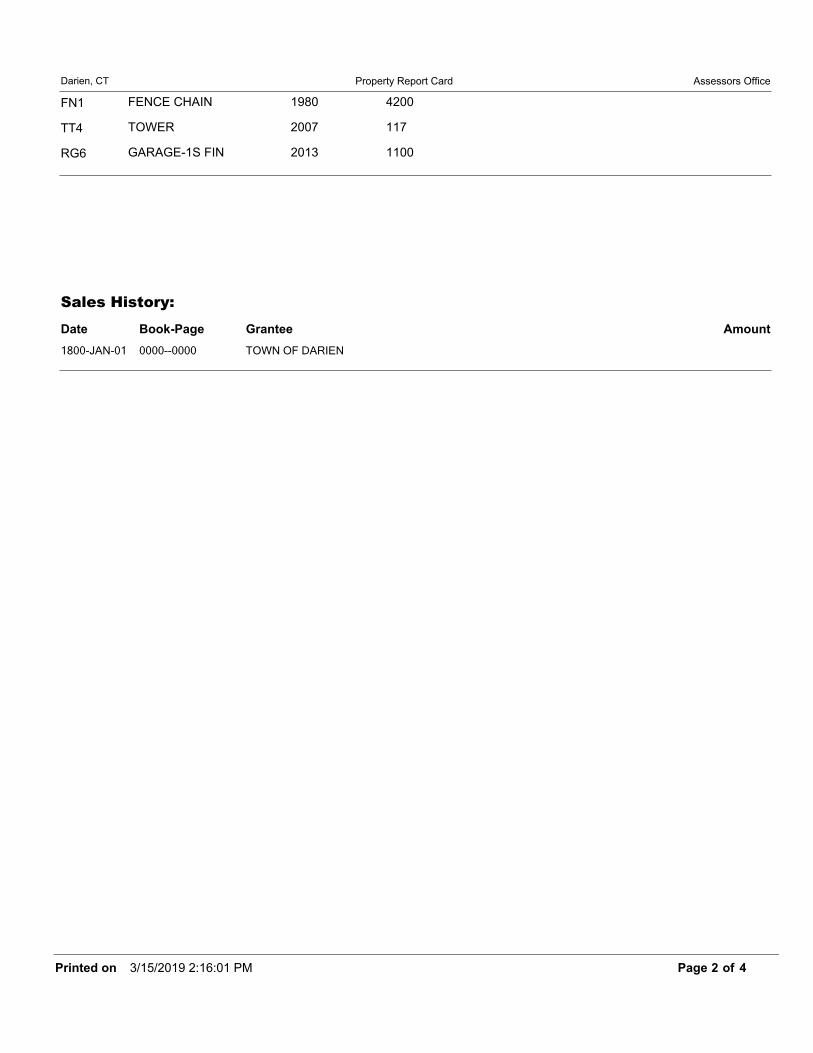
Darien, CT Assessors OfficeProperty Report Card
Sales History:
Date Book-Page Grantee Amount
FN1 FENCE CHAIN 1980 4200
TT4 TOWER 2007 117
RG6 GARAGE-1S FIN 2013 1100
1800-JAN-01 0000--0000 TOWN OF DARIEN
3/15/2019 2:16:01 PMPrinted on Page 2 of 4

Darien, CT Assessors OfficeProperty Report Card
SKETCH
6 A100 - VB1:1S/B 7770 Sq. Ft.7 A101 - VB1:1S/B 4130 Sq. Ft.8 A102 - VB1:1S/B 4576 Sq. Ft.9 A103 - VB1:1S/B 1815 Sq. Ft.10 A104 - VS1:1S 2520 Sq. Ft.11 CANPY RF/SLB - CP6:CANOPY ROOF/SLAB 490 Sq. Ft.12 CANPY RF-AVG - CP8:CANOPY RF-AVERAGE 920 Sq. Ft.1 AUTO PARTS/S - 047:AUTO PARTS/SERVICE 7770 Sq. Ft.2 AUTO PARTS/S - 047:AUTO PARTS/SERVICE 7770 Sq. Ft.3 AUTO PARTS/S - 047:AUTO PARTS/SERVICE 8706 Sq. Ft.4 MULTI-USE OF - 082:MULTI-USE OFFICE 4130 Sq. Ft.5 AUTO PARTS/S - 047:AUTO PARTS/SERVICE 4576 Sq. Ft.6 AUTO PARTS/S - 047:AUTO PARTS/SERVICE 2520 Sq. Ft.8 AUTO PARTS/S - 047:AUTO PARTS/SERVICE 1815 Sq. Ft.9 AUTO PARTS/S - 047:AUTO PARTS/SERVICE 1815 Sq. Ft.2 FENCE CHAI - FN1:FENCE CHAIN 4200 Sq. Ft.3 BR/ST SHED - RS3:BRICK/STN UTILITY SHED 90 Sq. Ft.4 GAR-1S FIN - RG6:GARAGE-1S FIN 1100 Sq. Ft.5 TOWER CELL - TT4:TOWER CELLULAR 117 Sq. Ft.6 METAL SHED - SH3:FINISHED METAL SHED 720 Sq. Ft.2 OVRHD DR - OD1:OVERHEAD DR-WOOD/MTL 144 Sq. Ft.1 ASPH PAVE - PA1:ASPHALT OR BLACKTOP PAVING 35000 Sq. Ft.1 OVRHD DR - OD1:OVERHEAD DR-WOOD/MTL 196 Sq. Ft.7 TOWER CELL - TT4:TOWER CELLULAR 110 Sq. Ft.
PHOTO
Sketch Legend
3/15/2019 2:16:01 PMPrinted on Page 3 of 4

Darien, CT Assessors OfficeProperty Report Card
3 OVRHD DR - OD1:OVERHEAD DR-WOOD/MTL 120 Sq. Ft.4 OVRHD DR - OD1:OVERHEAD DR-WOOD/MTL 160 Sq. Ft.
3/15/2019 2:16:01 PMPrinted on Page 4 of 4


March 05, 2019 117 Ft Monopole Tower Structural Analysis CCI BU No 806352 Project Number 37519-0798.001.7805, Order 478896, Revision 0 Page 2
tnxTower Report - version 8.0.5.0
TABLE OF CONTENTS 1) INTRODUCTION 2) ANALYSIS CRITERIA Table 1 - Proposed Equipment Configuration Table 2 - Other Considered Equipment 3) ANALYSIS PROCEDURE Table 3 - Documents Provided 3.1) Analysis Method 3.2) Assumptions 4) ANALYSIS RESULTS Table 4 - Section Capacity (Summary) Table 5 – Tower Component Stresses vs. Capacity 4.1) Recommendations 5) APPENDIX A tnxTower Output 6) APPENDIX B Base Level Drawing 7) APPENDIX C Additional Calculations

March 05, 2019 117 Ft Monopole Tower Structural Analysis CCI BU No 806352 Project Number 37519-0798.001.7805, Order 478896, Revision 0 Page 3
tnxTower Report - version 8.0.5.0
1) INTRODUCTION This tower is a 117 ft Monopole tower designed by VALMONT. 2) ANALYSIS CRITERIA TIA-222 Revision: TIA-222-H Risk Category: II Wind Speed: 120 mph Exposure Category: C Topographic Factor: 1 Ice Thickness: 1.5 in Wind Speed with Ice: 50 mph Service Wind Speed: 60 mph
Table 1 - Proposed Equipment Configuration
Mounting Level (ft)
Center Line
Elevation (ft)
Number of
Antennas
Antenna Manufacturer
Antenna Model Number of Feed Lines
Feed Line Size
(in)
89.0 89.0
2 cci antennas OPA-65R-LCUU-H6 w/
Mount Pipe
12 2 4
1-1/4 3/8 5/8
1 cci antennas OPA-65R-LCUU-H8 w/
Mount Pipe
1 cci antennas TPA-65R-LCUUUU-H8 w/
Mount Pipe
6 cci antennas TPX-070821
3 ericsson RRUS 11
3 ericsson RRUS 32 B2
3 ericsson RRUS 32 B30
3 ericsson RRUS 4426 B66
6 powerwave
technologies 7020.00
3 powerwave tech 7770.00 w/ Mount Pipe
6 powerwave tech LGP21401
2 quintel technology QS66512-2 w/ Mount Pipe
2 raycap DC6-48-60-18-8F
1 tower mounts Miscellaneous [NA 509-3]
1 tower mounts Platform Mount [LP 715-1]
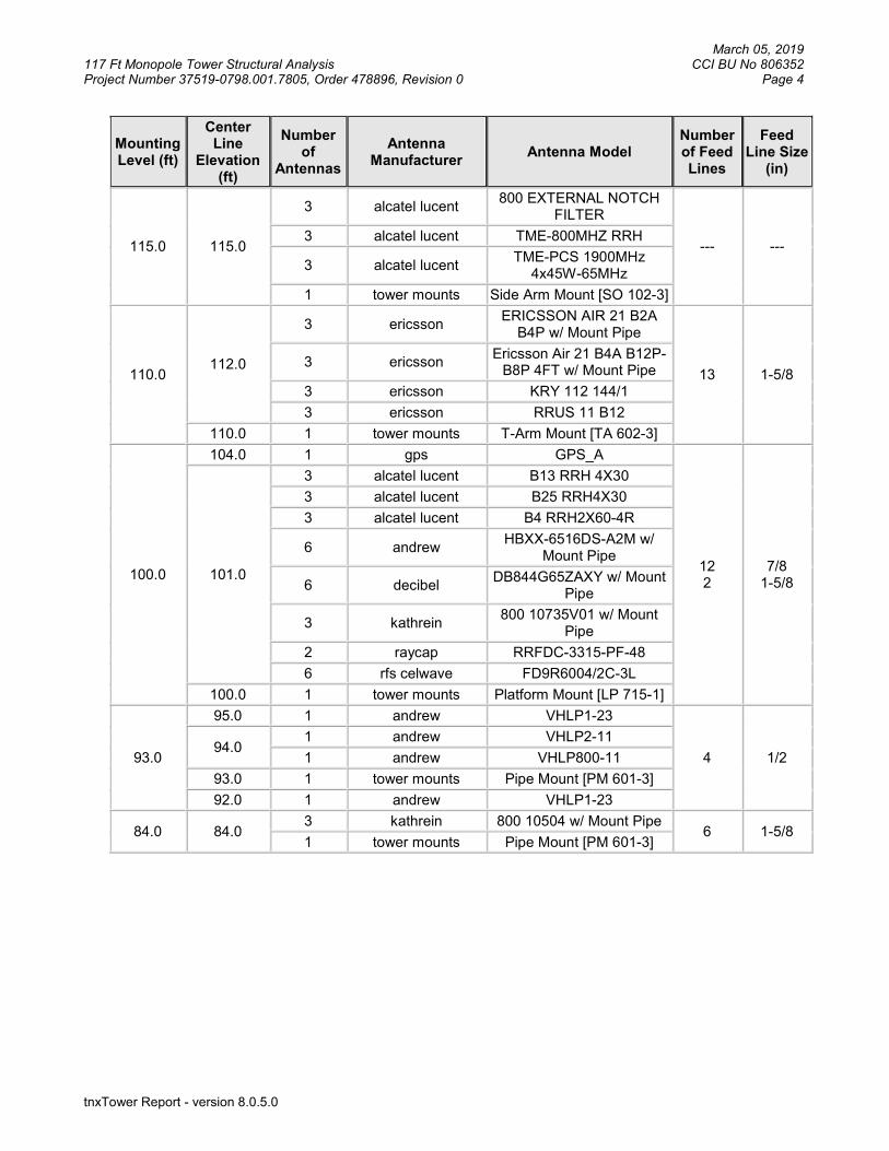
Table 2 - Other Considered Equipment
Mounting Level (ft)
Center Line
Elevation (ft)
Number of
Antennas
Antenna Manufacturer
Antenna Model Number of Feed Lines
Feed Line Size
(in)
117.0
119.0
3 alcatel lucent TD-RRH8x20-25
3 1
1-1/4 5/8
9 rfs celwave ACU-A20-N
3 rfs celwave APXVSPP18-C-A20 w/ MP
3 rfs celwave APXVTM14-ALU-I20 w/ MP
117.0 1 tower mounts Stabilizer Bars
1 tower mounts T-Arm Mount [TA 702-3]
March 05, 2019 117 Ft Monopole Tower Structural Analysis CCI BU No 806352 Project Number 37519-0798.001.7805, Order 478896, Revision 0 Page 4
tnxTower Report - version 8.0.5.0
Mounting Level (ft)
Center Line
Elevation (ft)
Number of
Antennas
Antenna Manufacturer
Antenna Model Number of Feed Lines
Feed Line Size
(in)
115.0 115.0
3 alcatel lucent 800 EXTERNAL NOTCH
FILTER
--- --- 3 alcatel lucent TME-800MHZ RRH
3 alcatel lucent TME-PCS 1900MHz
4x45W-65MHz
1 tower mounts Side Arm Mount [SO 102-3]
110.0 112.0
3 ericsson ERICSSON AIR 21 B2A
B4P w/ Mount Pipe
13 1-5/8 3 ericsson
Ericsson Air 21 B4A B12P-B8P 4FT w/ Mount Pipe
3 ericsson KRY 112 144/1
3 ericsson RRUS 11 B12
110.0 1 tower mounts T-Arm Mount [TA 602-3]
100.0
104.0 1 gps GPS_A
12 2
7/8 1-5/8
101.0
3 alcatel lucent B13 RRH 4X30
3 alcatel lucent B25 RRH4X30
3 alcatel lucent B4 RRH2X60-4R
6 andrew HBXX-6516DS-A2M w/
Mount Pipe
6 decibel DB844G65ZAXY w/ Mount
Pipe
3 kathrein 800 10735V01 w/ Mount
Pipe
2 raycap RRFDC-3315-PF-48
6 rfs celwave FD9R6004/2C-3L
100.0 1 tower mounts Platform Mount [LP 715-1]
93.0
95.0 1 andrew VHLP1-23
4 1/2 94.0
1 andrew VHLP2-11
1 andrew VHLP800-11
93.0 1 tower mounts Pipe Mount [PM 601-3]
92.0 1 andrew VHLP1-23
84.0 84.0 3 kathrein 800 10504 w/ Mount Pipe
6 1-5/8 1 tower mounts Pipe Mount [PM 601-3]

March 05, 2019 117 Ft Monopole Tower Structural Analysis CCI BU No 806352 Project Number 37519-0798.001.7805, Order 478896, Revision 0 Page 5
tnxTower Report - version 8.0.5.0
3) ANALYSIS PROCEDURE
Table 3 - Documents Provided
Document Remarks Reference Source
4-GEOTECHNICAL REPORTS FDH, 1307951600, 9/26/13 217769 CCISITES
4-TOWER FOUNDATION DRAWINGS/DESIGN/SPECS
FDH, 1308201500, 6/7/13 3907710 CCISITES
4-TOWER MANUFACTURER DRAWINGS
Valmont, 10844-92, 5/19/92 217772 CCISITES
4-POST-MODIFICATION INSPECTION
Sabre, 11-1114, 12/7/10 2785508 CCISITES
4-POST-MODIFICATION INSPECTION
TEP, 131001.806352, 11/7/13 4069331 CCISITES
4-POST-MODIFICATION INSPECTION
TEP, 25562, 5/12/14 5077215 CCISITES
4-POST-MODIFICATION INSPECTION
GPD, 2007278.24, 03/11/08 2218625 CCISITES
4-POST-MODIFICATION INSPECTION
TEP, 131001.806352, 11/7/2013 6122311 CCISITES
4-POST-MODIFICATION INSPECTION
TEP, 25562, 4/6/2016 6232380 CCISITES
4-TOWER REINFORCEMENT DESIGN/DRAWINGS/DATA
GPD, 2007178.68, 2/16/2007 1094732 CCISITES
4-TOWER REINFORCEMENT DESIGN/DRAWINGS/DATA
TEP, 102000.39, 11/4/2010 2743848 CCISITES
4-TOWER REINFORCEMENT DESIGN/DRAWINGS/DATA
TEP, 127875, 12/10/2012 4062469 CCISITES
4-TOWER REINFORCEMENT DESIGN/DRAWINGS/DATA
TEP, 25562.12516, 12/20/2013 4115809 CCISITES
4-TOWER REINFORCEMENT DESIGN/DRAWINGS/DATA
PJF, 37515-1078.005.7700, 11/12/2015
5969651 CCISITES
4-TOWER REINFORCEMENT DESIGN/DRAWINGS/DATA
PJF, 37516-0051, 2/1/2016 6083070 CCISITES
3.1) Analysis Method
tnxTower (version 8.0.5.0), a commercially available analysis software package, was used to create a three-dimensional model of the tower and calculate member stresses for various loading cases. Selected output from the analysis is included in Appendix A.
3.2) Assumptions
1) Tower and structures were built in accordance with the manufacturer’s specifications. 2) The tower and structures have been maintained in accordance with the manufacturer’s
specification. 3) The configuration of antennas, transmission cables, mounts and other appurtenances are as
specified in Tables 1 and 2 and the referenced drawings. 4) Monopole was reinforced in conformance with the referenced modification drawings. This analysis may be affected if any assumptions are not valid or have been made in error. Paul J. Ford & Company should be notified to determine the effect on the structural integrity of the tower.
March 05, 2019 117 Ft Monopole Tower Structural Analysis CCI BU No 806352 Project Number 37519-0798.001.7805, Order 478896, Revision 0 Page 6
tnxTower Report - version 8.0.5.0
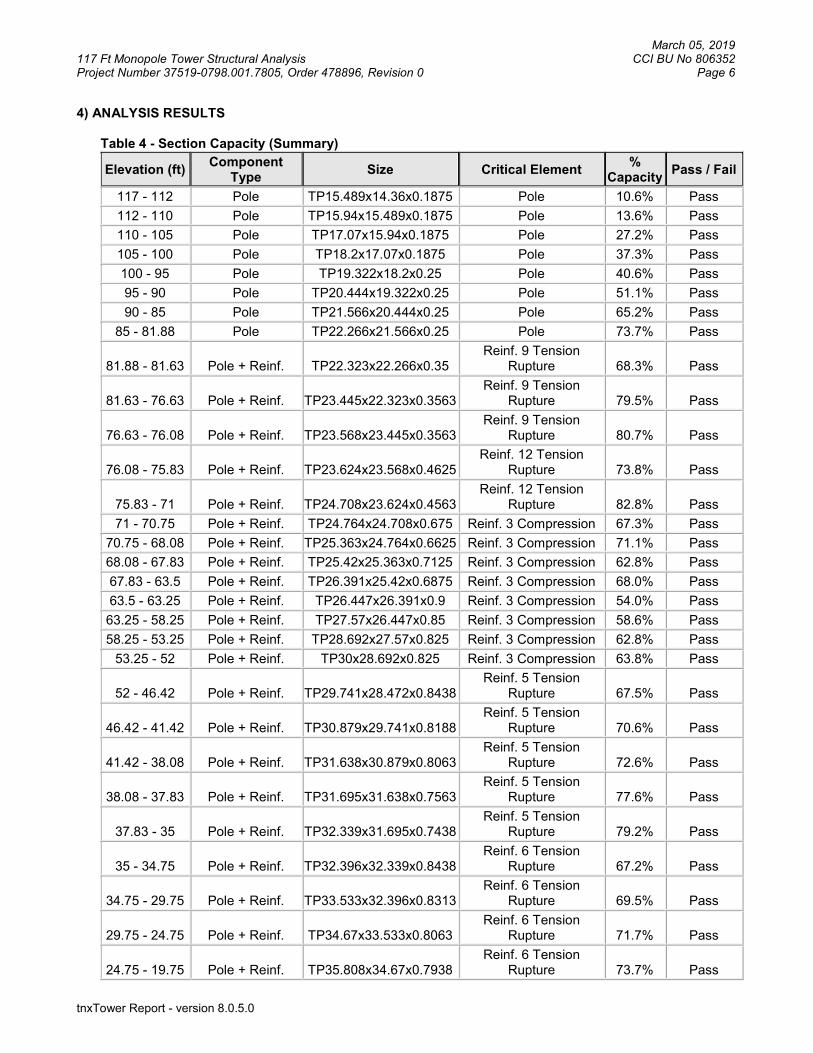
4) ANALYSIS RESULTS
Table 4 - Section Capacity (Summary)
Elevation (ft) Component
Type Size Critical Element
% Capacity
Pass / Fail
117 - 112 Pole TP15.489x14.36x0.1875 Pole 10.6% Pass
112 - 110 Pole TP15.94x15.489x0.1875 Pole 13.6% Pass
110 - 105 Pole TP17.07x15.94x0.1875 Pole 27.2% Pass
105 - 100 Pole TP18.2x17.07x0.1875 Pole 37.3% Pass
100 - 95 Pole TP19.322x18.2x0.25 Pole 40.6% Pass
95 - 90 Pole TP20.444x19.322x0.25 Pole 51.1% Pass
90 - 85 Pole TP21.566x20.444x0.25 Pole 65.2% Pass
85 - 81.88 Pole TP22.266x21.566x0.25 Pole 73.7% Pass
81.88 - 81.63 Pole + Reinf. TP22.323x22.266x0.35 Reinf. 9 Tension
Rupture 68.3% Pass
81.63 - 76.63 Pole + Reinf. TP23.445x22.323x0.3563 Reinf. 9 Tension
Rupture 79.5% Pass
76.63 - 76.08 Pole + Reinf. TP23.568x23.445x0.3563 Reinf. 9 Tension
Rupture 80.7% Pass
76.08 - 75.83 Pole + Reinf. TP23.624x23.568x0.4625 Reinf. 12 Tension
Rupture 73.8% Pass
75.83 - 71 Pole + Reinf. TP24.708x23.624x0.4563 Reinf. 12 Tension
Rupture 82.8% Pass
71 - 70.75 Pole + Reinf. TP24.764x24.708x0.675 Reinf. 3 Compression 67.3% Pass
70.75 - 68.08 Pole + Reinf. TP25.363x24.764x0.6625 Reinf. 3 Compression 71.1% Pass
68.08 - 67.83 Pole + Reinf. TP25.42x25.363x0.7125 Reinf. 3 Compression 62.8% Pass
67.83 - 63.5 Pole + Reinf. TP26.391x25.42x0.6875 Reinf. 3 Compression 68.0% Pass
63.5 - 63.25 Pole + Reinf. TP26.447x26.391x0.9 Reinf. 3 Compression 54.0% Pass
63.25 - 58.25 Pole + Reinf. TP27.57x26.447x0.85 Reinf. 3 Compression 58.6% Pass
58.25 - 53.25 Pole + Reinf. TP28.692x27.57x0.825 Reinf. 3 Compression 62.8% Pass
53.25 - 52 Pole + Reinf. TP30x28.692x0.825 Reinf. 3 Compression 63.8% Pass
52 - 46.42 Pole + Reinf. TP29.741x28.472x0.8438 Reinf. 5 Tension
Rupture 67.5% Pass
46.42 - 41.42 Pole + Reinf. TP30.879x29.741x0.8188 Reinf. 5 Tension
Rupture 70.6% Pass
41.42 - 38.08 Pole + Reinf. TP31.638x30.879x0.8063 Reinf. 5 Tension
Rupture 72.6% Pass
38.08 - 37.83 Pole + Reinf. TP31.695x31.638x0.7563 Reinf. 5 Tension
Rupture 77.6% Pass
37.83 - 35 Pole + Reinf. TP32.339x31.695x0.7438 Reinf. 5 Tension
Rupture 79.2% Pass
35 - 34.75 Pole + Reinf. TP32.396x32.339x0.8438 Reinf. 6 Tension
Rupture 67.2% Pass
34.75 - 29.75 Pole + Reinf. TP33.533x32.396x0.8313 Reinf. 6 Tension
Rupture 69.5% Pass
29.75 - 24.75 Pole + Reinf. TP34.67x33.533x0.8063 Reinf. 6 Tension
Rupture 71.7% Pass
24.75 - 19.75 Pole + Reinf. TP35.808x34.67x0.7938 Reinf. 6 Tension
Rupture 73.7% Pass

March 05, 2019 117 Ft Monopole Tower Structural Analysis CCI BU No 806352 Project Number 37519-0798.001.7805, Order 478896, Revision 0 Page 7
tnxTower Report - version 8.0.5.0
Elevation (ft) Component
Type Size Critical Element
% Capacity
Pass / Fail
19.75 - 14.75 Pole + Reinf. TP36.945x35.808x0.7688 Reinf. 6 Tension
Rupture 75.6% Pass
14.75 - 12.5 Pole + Reinf. TP37.457x36.945x0.7688 Reinf. 6 Tension
Rupture 76.3% Pass
12.5 - 12.25 Pole + Reinf. TP37.514x37.457x0.7688 Reinf. 4 Tension
Rupture 77.3% Pass
12.25 - 11 Pole + Reinf. TP37.798x37.514x0.7688 Reinf. 4 Tension
Rupture 77.7% Pass
11 - 10.75 Pole + Reinf. TP37.855x37.798x0.9688 Reinf. 4 Tension
Rupture 62.2% Pass
10.75 - 5.75 Pole + Reinf. TP38.992x37.855x0.9438 Reinf. 4 Tension
Rupture 63.7% Pass
5.75 - 2.5 Pole + Reinf. TP39.731x38.992x0.9438 Reinf. 4 Tension
Rupture 64.6% Pass
2.5 - 2.25 Pole + Reinf. TP39.788x39.731x0.9688 Reinf. 4 Tension
Rupture 60.6% Pass
2.25 - 0 Pole + Reinf. TP40.3x39.788x0.9688 Reinf. 4 Tension
Rupture 61.2% Pass
Summary
Pole 73.7% Pass
Reinforcement 82.8% Pass
Overall 82.8% Pass
Table 5 - Tower Component Stresses vs. Capacity – LC5
Notes Component Elevation (ft) % Capacity Pass / Fail
1 Anchor Rods 0 61.9 Pass
1 Base Plate 0 37.5 Pass
1 Base Foundation Structural Steel
0 67.6 Pass
1 Base Foundation Soil Interaction
0 44.9 Pass
1 Flange 100 33.7 Pass
1 Flange 110 13.2 Pass
Structure Rating (max from all components) = 82.8%
Notes: 1) See additional documentation in “Appendix C – Additional Calculations” for calculations supporting the % capacity
consumed. All ratings per TIA-222-H section 15.5. 4.1) Recommendations
The monopole and its foundation have sufficient capacity to carry the proposed loading configuration. No modifications are required at this time.

March 05, 2019 117 Ft Monopole Tower Structural Analysis CCI BU No 806352 Project Number 37519-0798.001.7805, Order 478896, Revision 0 Page 8
tnxTower Report - version 8.0.5.0
APPENDIX A
TNXTOWER OUTPUT

March 05, 2019 117 Ft Monopole Tower Structural Analysis CCI BU No 806352 Project Number 37519-0798.001.7805, Order 478896, Revision 0 Page 9
tnxTower Report - version 8.0.5.0
Tower Input Data The tower is a monopole. This tower is designed using the TIA-222-H standard. The following design criteria apply:
1) Tower is located in Fairfield County, Connecticut. 2) Tower base elevation above sea level: 42.2500 ft. 3) Basic wind speed of 120 mph. 4) Risk Category II. 5) Exposure Category C. 6) Simplified Topographic Factor Procedure for wind speed-up calculations is used. 7) Topographic Category: 1. 8) Crest Height: 0.0000 ft. 9) Nominal ice thickness of 1.5000 in. 10) Ice thickness is considered to increase with height. 11) Ice density of 56.00 pcf. 12) A wind speed of 50 mph is used in combination with ice. 13) Temperature drop of 50 °F. 14) Deflections calculated using a wind speed of 60 mph. 15) TIA-222-H ANNEX S. 16) A non-linear (P-delta) analysis was used. 17) Pressures are calculated at each section. 18) Stress ratio used in pole design is 1.05. 19) Tower analysis based on target reliabilities in accordance with Annex S. 20) Load Modification Factors used: Kes(Fw) = 0.95, Kes(ti) = 0.85. 21) Local bending stresses due to climbing loads, feed line supports, and appurtenance mounts are
not considered.
Options
Consider Moments - Legs Distribute Leg Loads As Uniform Use ASCE 10 X-Brace Ly Rules Consider Moments - Horizontals Assume Legs Pinned Calculate Redundant Bracing Forces Consider Moments - Diagonals √ Assume Rigid Index Plate Ignore Redundant Members in FEA Use Moment Magnification √ Use Clear Spans For Wind Area SR Leg Bolts Resist Compression Use Code Stress Ratios Use Clear Spans For KL/r All Leg Panels Have Same Allowable
√ Use Code Safety Factors - Guys Retension Guys To Initial Tension Offset Girt At Foundation Escalate Ice √ Bypass Mast Stability Checks √ Consider Feed Line Torque Always Use Max Kz √ Use Azimuth Dish Coefficients Include Angle Block Shear Check Use Special Wind Profile √ Project Wind Area of Appurt. Use TIA-222-H Bracing Resist.
Exemption Include Bolts In Member Capacity Autocalc Torque Arm Areas Use TIA-222-H Tension Splice
Exemption Leg Bolts Are At Top Of Section Add IBC .6D+W Combination Poles Secondary Horizontal Braces Leg Sort Capacity Reports By Component √ Include Shear-Torsion Interaction Use Diamond Inner Bracing (4 Sided) Triangulate Diamond Inner Bracing Always Use Sub-Critical Flow SR Members Have Cut Ends Treat Feed Line Bundles As Cylinder Use Top Mounted Sockets SR Members Are Concentric Ignore KL/ry For 60 Deg. Angle Legs Pole Without Linear Attachments Pole With Shroud Or No
Appurtenances Outside and Inside Corner Radii Are
Known
Tapered Pole Section Geometry Section Elevation
ft
Section Length
ft
Splice Length
ft
Number of
Sides
Top Diameter
in
Bottom Diameter
in
Wall Thickness
in
Bend Radius
in
Pole Grade

March 05, 2019 117 Ft Monopole Tower Structural Analysis CCI BU No 806352 Project Number 37519-0798.001.7805, Order 478896, Revision 0 Page 10
tnxTower Report - version 8.0.5.0
Section Elevation
ft
Section Length
ft
Splice Length
ft
Number of
Sides
Top Diameter
in
Bottom Diameter
in
Wall Thickness
in
Bend Radius
in
Pole Grade
L1 117.0000-112.0000
5.0000 0.00 12 14.3600 15.4886 0.1875 0.7500 A572-65 (65 ksi)
L2 112.0000-110.0000
2.0000 0.00 12 15.4886 15.9400 0.1875 0.7500 A572-65 (65 ksi)
L3 110.0000-105.0000
5.0000 0.00 12 15.9400 17.0700 0.1875 0.7500 A572-65 (65 ksi)
L4 105.0000-100.0000
5.0000 0.00 12 17.0700 18.2000 0.1875 0.7500 A572-65 (65 ksi)
L5 100.0000-95.0000
5.0000 0.00 12 18.2000 19.3221 0.2500 1.0000 A572-65 (65 ksi)
L6 95.0000-90.0000
5.0000 0.00 12 19.3221 20.4442 0.2500 1.0000 A572-65 (65 ksi)
L7 90.0000-85.0000
5.0000 0.00 12 20.4442 21.5663 0.2500 1.0000 A572-65 (65 ksi)
L8 85.0000-81.8800
3.1200 0.00 12 21.5663 22.2665 0.2500 1.0000 A572-65 (65 ksi)
L9 81.8800-81.6300
0.2500 0.00 12 22.2665 22.3226 0.3500 1.4000 A572-65 (65 ksi)
L10 81.6300-76.6300
5.0000 0.00 12 22.3226 23.4447 0.3563 1.4250 A572-65 (65 ksi)
L11 76.6300-76.0800
0.5500 0.00 12 23.4447 23.5681 0.3563 1.4250 A572-65 (65 ksi)
L12 76.0800-75.8300
0.2500 0.00 12 23.5681 23.6242 0.4625 1.8500 A572-65 (65 ksi)
L13 75.8300-71.0000
4.8300 0.00 12 23.6242 24.7082 0.4562 1.8250 A572-65 (65 ksi)
L14 71.0000-70.7500
0.2500 0.00 12 24.7082 24.7643 0.6750 2.7000 A572-65 (65 ksi)
L15 70.7500-68.0800
2.6700 0.00 12 24.7643 25.3635 0.6625 2.6500 A572-65 (65 ksi)
L16 68.0800-67.8300
0.2500 0.00 12 25.3635 25.4196 0.7125 2.8500 A572-65 (65 ksi)
L17 67.8300-63.5000
4.3300 0.00 12 25.4196 26.3913 0.6875 2.7500 A572-65 (65 ksi)
L18 63.5000-63.2500
0.2500 0.00 12 26.3913 26.4474 0.9000 3.6000 A572-65 (65 ksi)
L19 63.2500-58.2500
5.0000 0.00 12 26.4474 27.5695 0.8500 3.4000 A572-65 (65 ksi)
L20 58.2500-53.2500
5.0000 0.00 12 27.5695 28.6916 0.8250 3.3000 A572-65 (65 ksi)
L21 53.2500-47.4200
5.8300 4.58 12 28.6916 30.0000 0.8250 3.3000 A572-65 (65 ksi)
L22 47.4200-46.4200
5.5800 0.00 12 28.4722 29.7414 0.8438 3.3750 A572-65 (65 ksi)
L23 46.4200-41.4200
5.0000 0.00 12 29.7414 30.8787 0.8187 3.2750 A572-65 (65 ksi)
L24 41.4200-38.0800
3.3400 0.00 12 30.8787 31.6384 0.8063 3.2250 A572-65 (65 ksi)
L25 38.0800-37.8300
0.2500 0.00 12 31.6384 31.6952 0.7562 3.0250 A572-65 (65 ksi)
L26 37.8300-35.0000
2.8300 0.00 12 31.6952 32.3390 0.7438 2.9750 A572-65 (65 ksi)
L27 35.0000-34.7500
0.2500 0.00 12 32.3390 32.3958 0.8438 3.3750 A572-65 (65 ksi)
L28 34.7500-29.7500
5.0000 0.00 12 32.3958 33.5331 0.8313 3.3250 A572-65 (65 ksi)
L29 29.7500-24.7500
5.0000 0.00 12 33.5331 34.6704 0.8063 3.2250 A572-65 (65 ksi)
L30 24.7500-19.7500
5.0000 0.00 12 34.6704 35.8077 0.7937 3.1750 A572-65 (65 ksi)
L31 19.7500-14.7500
5.0000 0.00 12 35.8077 36.9450 0.7688 3.0750 A572-65 (65 ksi)
L32 14.7500-12.5000
2.2500 0.00 12 36.9450 37.4568 0.7688 3.0750 A572-65 (65 ksi)
L33 12.5000-12.2500
0.2500 0.00 12 37.4568 37.5136 0.7688 3.0750 A572-65 (65 ksi)
L34 12.2500-11.0000
1.2500 0.00 12 37.5136 37.7980 0.7688 3.0750 A572-65 (65 ksi)
L35 11.0000- 0.2500 0.00 12 37.7980 37.8548 0.9688 3.8750 A572-65

March 05, 2019 117 Ft Monopole Tower Structural Analysis CCI BU No 806352 Project Number 37519-0798.001.7805, Order 478896, Revision 0 Page 11
tnxTower Report - version 8.0.5.0
Section Elevation
ft
Section Length
ft
Splice Length
ft
Number of
Sides
Top Diameter
in
Bottom Diameter
in
Wall Thickness
in
Bend Radius
in
Pole Grade
10.7500 (65 ksi) L36 10.7500-
5.7500 5.0000 0.00 12 37.8548 38.9921 0.9437 3.7750 A572-65
(65 ksi) L37 5.7500-2.5000 3.2500 0.00 12 38.9921 39.7314 0.9437 3.7750 A572-65
(65 ksi) L38 2.5000-2.2500 0.2500 0.00 12 39.7314 39.7882 0.9688 3.8750 A572-65
(65 ksi) L39 2.2500-0.0000 2.2500 12 39.7882 40.3000 0.9688 3.8750 A572-65
(65 ksi)
Tapered Pole Properties Section Tip Dia.
in Area in2
I in4
r in
C in
I/C in3
J in4
It/Q in2
w in
w/t
L1 14.8004 8.5566 219.3727 5.0738 7.4385 29.4916 444.5085 4.2113 3.3460 17.845 15.9688 9.2380 276.0632 5.4778 8.0231 34.4086 559.3790 4.5467 3.6484 19.458
L2 15.9688 9.2380 276.0632 5.4778 8.0231 34.4086 559.3790 4.5467 3.6484 19.458 16.4362 9.5106 301.2254 5.6394 8.2569 36.4816 610.3643 4.6808 3.7694 20.104
L3 16.4362 9.5106 301.2254 5.6394 8.2569 36.4816 610.3643 4.6808 3.7694 20.104 17.6060 10.1928 370.8116 6.0439 8.8423 41.9363 751.3649 5.0166 4.0723 21.719
L4 17.6060 10.1928 370.8116 6.0439 8.8423 41.9363 751.3649 5.0166 4.0723 21.719 18.7759 10.8750 450.3655 6.4485 9.4276 47.7710 912.5625 5.3524 4.3751 23.334
L5 18.7538 14.4498 594.2582 6.4261 9.4276 63.0339 1204.1282 7.1117 4.2076 16.83 19.9155 15.3530 712.8159 6.8278 10.0088 71.2186 1444.3583 7.5563 4.5083 18.033
L6 19.9155 15.3530 712.8159 6.8278 10.0088 71.2186 1444.3583 7.5563 4.5083 18.033 21.0772 16.2563 846.1780 7.2295 10.5901 79.9028 1714.5860 8.0009 4.8090 19.236
L7 21.0772 16.2563 846.1780 7.2295 10.5901 79.9028 1714.5860 8.0009 4.8090 19.236 22.2389 17.1596 995.2158 7.6312 11.1713 89.0865 2016.5769 8.4454 5.1098 20.439
L8 22.2389 17.1596 995.2158 7.6312 11.1713 89.0865 2016.5769 8.4454 5.1098 20.439 22.9638 17.7233 1096.5439 7.8819 11.5340 95.0702 2221.8952 8.7229 5.2974 21.19
L9 22.9285 24.6999 1514.3380 7.8461 11.5340 131.2929 3068.4593 12.1565 5.0294 14.37 22.9866 24.7631 1525.9976 7.8662 11.5631 131.9713 3092.0849 12.1877 5.0445 14.413
L10 22.9844 25.1981 1551.9225 7.8640 11.5631 134.2133 3144.6158 12.4018 5.0277 14.113 24.1461 26.4853 1802.1075 8.2657 12.1444 148.3906 3651.5583 13.0353 5.3284 14.957
L11 24.1461 26.4853 1802.1075 8.2657 12.1444 148.3906 3651.5583 13.0353 5.3284 14.957 24.2738 26.6269 1831.1645 8.3099 12.2083 149.9935 3710.4358 13.1050 5.3615 15.05
L12 24.2364 34.4101 2344.8049 8.2718 12.2083 192.0666 4751.2105 16.9356 5.0768 10.977 24.2945 34.4936 2361.9274 8.2919 12.2374 193.0097 4785.9052 16.9767 5.0918 11.009
L13 24.2967 34.0367 2331.8962 8.2941 12.2374 190.5556 4725.0538 16.7518 5.1085 11.197 25.4188 35.6291 2674.7519 8.6822 12.7988 208.9840 5419.7726 17.5356 5.3990 11.834
L14 25.3417 52.2361 3851.0504 8.6039 12.7988 300.8907 7803.2722 25.7090 4.8128 7.13 25.3998 52.3581 3878.0840 8.6240 12.8279 302.3164 7858.0497 25.7690 4.8278 7.152
L15 25.4042 51.4151 3812.1960 8.6284 12.8279 297.1801 7724.5426 25.3050 4.8613 7.338 26.0245 52.6934 4103.6515 8.8430 13.1383 312.3430 8315.1104 25.9341 5.0219 7.58
L16 26.0069 56.5555 4386.6145 8.8251 13.1383 333.8803 8888.4703 27.8349 4.8879 6.86 26.0650 56.6842 4416.6342 8.8451 13.1673 335.4232 8949.2983 27.8983 4.9029 6.881
L17 26.0738 54.7507 4274.6142 8.8541 13.1673 324.6375 8661.5273 26.9466 4.9699 7.229 27.0798 56.9018 4798.5264 9.2020 13.6707 351.0079 9723.1155 28.0054 5.2304 7.608
L18 27.0048 73.8739 6127.1945 9.1259 13.6707 448.1988 12415.3571
36.3585 4.6609 5.179
27.0629 74.0365 6167.7404 9.1460 13.6998 450.2076 12497.5142
36.4385 4.6759 5.195
L19 27.0805 70.0602 5859.3568 9.1639 13.6998 427.6975 11872.6453
34.4815 4.8099 5.659
28.2422 73.1314 6664.1887 9.5656 14.2810 466.6466 13503.4532
35.9930 5.1106 6.013
L20 28.2511 71.0468 6486.3560 9.5745 14.2810 454.1942 13143.1157
34.9671 5.1776 6.276
29.4127 74.0277 7337.5186 9.9763 14.8623 493.7012 14867.8021
36.4342 5.4784 6.64
L21 29.4127 74.0277 7337.5186 9.9763 14.8623 493.7012 14867.8021
36.4342 5.4784 6.64
30.7673 77.5034 8420.3155 10.4446 15.5400 541.8478 17061.8421
38.1448 5.8290 7.065
L22 30.2574 75.0629 7313.4643 9.8910 14.7486 495.8759 14819.061 36.9437 5.3693 6.364

March 05, 2019 117 Ft Monopole Tower Structural Analysis CCI BU No 806352 Project Number 37519-0798.001.7805, Order 478896, Revision 0 Page 12
tnxTower Report - version 8.0.5.0
Section Tip Dia. in
Area in2
I in4
r in
C in
I/C in3
J in4
It/Q in2
w in
w/t
4 30.4929 78.5112 8368.3929 10.3453 15.4060 543.1894 16956.632
7 38.6408 5.7094 6.767
L23 30.5017 76.2509 8141.5343 10.3543 15.4060 528.4641 16496.9557
37.5284 5.7764 7.055
31.6791 79.2492 9140.2171 10.7615 15.9952 571.4368 18520.5578
39.0041 6.0812 7.427
L24 31.6835 78.0718 9011.9048 10.7659 15.9952 563.4148 18260.5625
38.4245 6.1147 7.584
32.4700 80.0441 9712.3001 11.0379 16.3887 592.6225 19679.7531
39.3953 6.3183 7.837
L25 32.4877 75.2018 9154.3794 11.0558 16.3887 558.5794 18549.2545
37.0121 6.4523 8.532
32.5466 75.3403 9205.0420 11.0762 16.4181 560.6630 18651.9107
37.0802 6.4676 8.552
L26 32.5510 74.1250 9063.8696 11.0806 16.4181 552.0645 18365.8572
36.4821 6.5011 8.741
33.2174 75.6666 9641.2248 11.3111 16.7516 575.5413 19535.7353
37.2408 6.6736 8.973
L27 33.1821 85.5685 10833.9993
11.2753 16.7516 646.7450 21952.6198
42.1142 6.4056 7.592
33.2410 85.7230 10892.7870
11.2956 16.7810 649.1130 22071.7397
42.1903 6.4208 7.61
L28 33.2454 84.4865 10744.1719
11.3001 16.7810 640.2569 21770.6051
41.5817 6.4543 7.765
34.4228 87.5306 11947.8787
11.7073 17.3702 687.8397 24209.6415
43.0799 6.7591 8.131
L29 34.4316 84.9630 11615.1421
11.7162 17.3702 668.6840 23535.4268
41.8162 6.8261 8.467
35.6090 87.9156 12868.6255
12.1234 17.9593 716.5451 26075.3242
43.2694 7.1309 8.845
L30 35.6134 86.5845 12683.1465
12.1278 17.9593 706.2173 25699.4934
42.6143 7.1644 9.026
36.7908 89.4913 14003.8890
12.5350 18.5484 754.9923 28375.6757
44.0449 7.4692 9.41
L31 36.7997 86.7345 13591.8940
12.5439 18.5484 732.7804 27540.8621
42.6881 7.5362 9.803
37.9771 89.5498 14958.8126
12.9511 19.1375 781.6491 30310.6098
44.0737 7.8410 10.2
L32 37.9771 89.5498 14958.8126
12.9511 19.1375 781.6491 30310.6098
44.0737 7.8410 10.2
38.5069 90.8166 15602.6980
13.1343 19.4026 804.1548 31615.2962
44.6972 7.9782 10.378
L33 38.5069 90.8166 15602.6980
13.1343 19.4026 804.1548 31615.2962
44.6972 7.9782 10.378
38.5658 90.9574 15675.3612
13.1547 19.4321 806.6751 31762.5316
44.7664 7.9934 10.398
L34 38.5658 90.9574 15675.3612
13.1547 19.4321 806.6751 31762.5316
44.7664 7.9934 10.398
38.8601 91.6612 16042.0605
13.2565 19.5793 819.3361 32505.5638
45.1128 8.0696 10.497
L35 38.7896 114.8841 19889.8087
13.1849 19.5793 1015.8569 40302.1448
56.5425 7.5336 7.777
38.8485 115.0615 19982.0817
13.2052 19.6088 1019.0366 40489.1150
56.6298 7.5488 7.792
L36 38.8573 112.1681 19506.0228
13.2142 19.6088 994.7588 39524.4905
55.2057 7.6158 8.07
40.0347 115.6242 21365.1878
13.6213 20.1979 1057.7918 43291.6630
56.9067 7.9206 8.393
L37 40.0347 115.6242 21365.1878
13.6213 20.1979 1057.7918 43291.6630
56.9067 7.9206 8.393
40.8000 117.8707 22634.8513
13.8860 20.5808 1099.8020 45864.3453
58.0124 8.1188 8.603
L38 40.7912 120.9151 23189.5527
13.8770 20.5808 1126.7544 46988.3207
59.5107 8.0518 8.311
40.8501 121.0925 23291.7583
13.8974 20.6103 1130.1030 47195.4171
59.5980 8.0670 8.327
L39 40.8501 121.0925 23291.7583
13.8974 20.6103 1130.1030 47195.4171
59.5980 8.0670 8.327
41.3799 122.6889 24225.167 14.0806 20.8754 1160.4648 49086.756 60.3838 8.2042 8.469
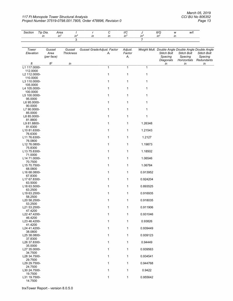
March 05, 2019 117 Ft Monopole Tower Structural Analysis CCI BU No 806352 Project Number 37519-0798.001.7805, Order 478896, Revision 0 Page 13
tnxTower Report - version 8.0.5.0
Section Tip Dia. in
Area in2
I in4
r in
C in
I/C in3
J in4
It/Q in2
w in
w/t
3 7
Tower
Elevation
ft
Gusset Area
(per face)
ft2
Gusset Thickness
in
Gusset Grade Adjust. Factor Af
Adjust. Factor
Ar
Weight Mult.
Double Angle Stitch Bolt Spacing
Diagonals in
Double Angle Stitch Bolt Spacing
Horizontals in
Double Angle Stitch Bolt Spacing
Redundants in
L1 117.0000-112.0000
1 1 1
L2 112.0000-110.0000
1 1 1
L3 110.0000-105.0000
1 1 1
L4 105.0000-100.0000
1 1 1
L5 100.0000-95.0000
1 1 1
L6 95.0000-90.0000
1 1 1
L7 90.0000-85.0000
1 1 1
L8 85.0000-81.8800
1 1 1
L9 81.8800-81.6300
1 1 1.26348
L10 81.6300-76.6300
1 1 1.21543
L11 76.6300-76.0800
1 1 1.2127
L12 76.0800-75.8300
1 1 1.19873
L13 75.8300-71.0000
1 1 1.18502
L14 71.0000-70.7500
1 1 1.06546
L15 70.7500-68.0800
1 1 1.06784
L16 68.0800-67.8300
1 1 0.913952
L17 67.8300-63.5000
1 1 0.924204
L18 63.5000-63.2500
1 1 0.893525
L19 63.2500-58.2500
1 1 0.916935
L20 58.2500-53.2500
1 1 0.918035
L21 53.2500-47.4200
1 1 0.911906
L22 47.4200-46.4200
1 1 0.931046
L23 46.4200-41.4200
1 1 0.93826
L24 41.4200-38.0800
1 1 0.939449
L25 38.0800-37.8300
1 1 0.939123
L26 37.8300-35.0000
1 1 0.94449
L27 35.0000-34.7500
1 1 0.939563
L28 34.7500-29.7500
1 1 0.934541
L29 29.7500-24.7500
1 1 0.944768
L30 24.7500-19.7500
1 1 0.9422
L31 19.7500-14.7500
1 1 0.955642
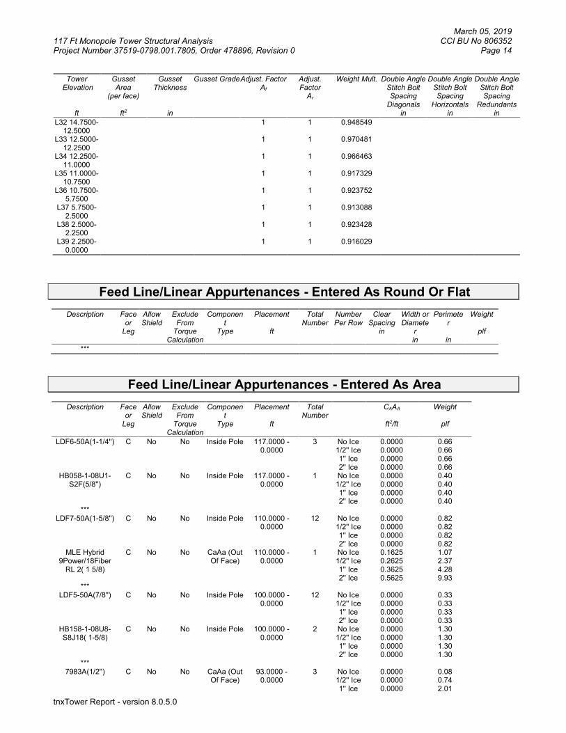
March 05, 2019 117 Ft Monopole Tower Structural Analysis CCI BU No 806352 Project Number 37519-0798.001.7805, Order 478896, Revision 0 Page 14
tnxTower Report - version 8.0.5.0
Tower Elevation
ft
Gusset Area
(per face)
ft2
Gusset Thickness
in
Gusset Grade Adjust. Factor Af
Adjust. Factor
Ar
Weight Mult.
Double Angle Stitch Bolt Spacing
Diagonals in
Double Angle Stitch Bolt Spacing
Horizontals in
Double Angle Stitch Bolt Spacing
Redundants in
L32 14.7500-12.5000
1 1 0.948549
L33 12.5000-12.2500
1 1 0.970481
L34 12.2500-11.0000
1 1 0.966463
L35 11.0000-10.7500
1 1 0.917329
L36 10.7500-5.7500
1 1 0.923752
L37 5.7500-2.5000
1 1 0.913088
L38 2.5000-2.2500
1 1 0.923428
L39 2.2500-0.0000
1 1 0.916029
Feed Line/Linear Appurtenances - Entered As Round Or Flat
Description Face or
Leg
Allow Shield
Exclude From
Torque Calculation
Component
Type
Placement
ft
Total Number
Number Per Row
Clear Spacing
in
Width or Diamete
r in
Perimeter
in
Weight
plf
***
Feed Line/Linear Appurtenances - Entered As Area
Description Face or
Leg
Allow Shield
Exclude From
Torque Calculation
Component
Type
Placement
ft
Total Number
CAAA
ft2/ft
Weight
plf
LDF6-50A(1-1/4'') C No No Inside Pole 117.0000 - 0.0000
3 No Ice 1/2'' Ice 1'' Ice 2'' Ice
0.0000 0.0000 0.0000 0.0000
0.66 0.66 0.66 0.66
HB058-1-08U1-S2F(5/8'')
C No No Inside Pole 117.0000 - 0.0000
1 No Ice 1/2'' Ice 1'' Ice 2'' Ice
0.0000 0.0000 0.0000 0.0000
0.40 0.40 0.40 0.40
*** LDF7-50A(1-5/8'') C No No Inside Pole 110.0000 -
0.0000 12 No Ice
1/2'' Ice 1'' Ice 2'' Ice
0.0000 0.0000 0.0000 0.0000
0.82 0.82 0.82 0.82
MLE Hybrid 9Power/18Fiber
RL 2( 1 5/8)
C No No CaAa (Out Of Face)
110.0000 - 0.0000
1 No Ice 1/2'' Ice 1'' Ice 2'' Ice
0.1625 0.2625 0.3625 0.5625
1.07 2.37 4.28 9.93
*** LDF5-50A(7/8'') C No No Inside Pole 100.0000 -
0.0000 12 No Ice
1/2'' Ice 1'' Ice 2'' Ice
0.0000 0.0000 0.0000 0.0000
0.33 0.33 0.33 0.33
HB158-1-08U8-S8J18( 1-5/8)
C No No Inside Pole 100.0000 - 0.0000
2 No Ice 1/2'' Ice 1'' Ice 2'' Ice
0.0000 0.0000 0.0000 0.0000
1.30 1.30 1.30 1.30
*** 7983A(1/2'') C No No CaAa (Out
Of Face) 93.0000 -
0.0000 3 No Ice
1/2'' Ice 1'' Ice
0.0000 0.0000 0.0000
0.08 0.74 2.01

March 05, 2019 117 Ft Monopole Tower Structural Analysis CCI BU No 806352 Project Number 37519-0798.001.7805, Order 478896, Revision 0 Page 15
tnxTower Report - version 8.0.5.0
Description Face or
Leg
Allow Shield
Exclude From
Torque Calculation
Component
Type
Placement
ft
Total Number
CAAA
ft2/ft
Weight
plf
2'' Ice 0.0000 6.39 7983A(1/2'') C No No CaAa (Out
Of Face) 84.0000 -
0.0000 1 No Ice
1/2'' Ice 1'' Ice 2'' Ice
0.0000 0.0000 0.0000 0.0000
0.08 0.74 2.01 6.39
7983A(1/2'') C No No CaAa (Out Of Face)
93.0000 - 84.0000
1 No Ice 1/2'' Ice 1'' Ice 2'' Ice
0.0580 0.1580 0.2580 0.4580
0.08 0.74 2.01 6.39
*** LDF6-50A(1-1/4'') C No No Inside Pole 89.0000 -
0.0000 12 No Ice
1/2'' Ice 1'' Ice 2'' Ice
0.0000 0.0000 0.0000 0.0000
0.66 0.66 0.66 0.66
2'' (Nominal) Conduit
C No No Inside Pole 89.0000 - 0.0000
2 No Ice 1/2'' Ice 1'' Ice 2'' Ice
0.0000 0.0000 0.0000 0.0000
0.72 0.72 0.72 0.72
FB-L98-002-XXX( 3/8'')
C No No Inside Pole 89.0000 - 0.0000
2 No Ice 1/2'' Ice 1'' Ice 2'' Ice
0.0000 0.0000 0.0000 0.0000
0.06 0.06 0.06 0.06
WR-VG82ST-BRDA( 5/8)
C No No Inside Pole 89.0000 - 0.0000
4 No Ice 1/2'' Ice 1'' Ice 2'' Ice
0.0000 0.0000 0.0000 0.0000
0.31 0.31 0.31 0.31
*** AVA7-50(1-5/8) C No No CaAa (Out
Of Face) 84.0000 -
0.0000 2 No Ice
1/2'' Ice 1'' Ice 2'' Ice
0.2010 0.3010 0.4010 0.6010
0.70 2.23 4.38
10.50 AVA7-50(1-5/8) C No No CaAa (Out
Of Face) 84.0000 -
0.0000 4 No Ice
1/2'' Ice 1'' Ice 2'' Ice
0.0000 0.0000 0.0000 0.0000
0.70 2.23 4.38
10.50 **
1'' Flat Reinforcement
C No No CaAa (Out Of Face)
72.5000 - 0.0000
1 No Ice 1/2'' Ice 1'' Ice 2'' Ice
0.1667 0.2778 0.3889 0.6111
0.00 0.00 0.00 0.00
3/4'' Flat Reinforcement
C No No CaAa (Out Of Face)
77.0800 - 72.5000
1 No Ice 1/2'' Ice 1'' Ice 2'' Ice
0.1250 0.2361 0.3472 0.5694
0.00 0.00 0.00 0.00
***
Feed Line/Linear Appurtenances Section Areas Tower Sectio
n
Tower Elevation
ft
Face AR
ft2
AF
ft2
CAAA
In Face ft2
CAAA
Out Face ft2
Weight
K
L1 117.0000-112.0000
A B C
0.000 0.000 0.000
0.000 0.000 0.000
0.000 0.000 0.000
0.000 0.000 0.000
0.00 0.00 0.01
L2 112.0000-110.0000
A B C
0.000 0.000 0.000
0.000 0.000 0.000
0.000 0.000 0.000
0.000 0.000 0.000
0.00 0.00 0.00
L3 110.0000-105.0000
A B C
0.000 0.000 0.000
0.000 0.000 0.000
0.000 0.000 0.000
0.000 0.000 0.813
0.00 0.00 0.07
L4 105.0000-100.0000
A B
0.000 0.000
0.000 0.000
0.000 0.000
0.000 0.000
0.00 0.00

March 05, 2019 117 Ft Monopole Tower Structural Analysis CCI BU No 806352 Project Number 37519-0798.001.7805, Order 478896, Revision 0 Page 16
tnxTower Report - version 8.0.5.0
Tower Sectio
n
Tower Elevation
ft
Face AR
ft2
AF
ft2
CAAA
In Face ft2
CAAA
Out Face ft2
Weight
K
C 0.000 0.000 0.000 0.813 0.07 L5 100.0000-
95.0000 A B C
0.000 0.000 0.000
0.000 0.000 0.000
0.000 0.000 0.000
0.000 0.000 0.813
0.00 0.00 0.10
L6 95.0000-90.0000 A B C
0.000 0.000 0.000
0.000 0.000 0.000
0.000 0.000 0.000
0.000 0.000 0.987
0.00 0.00 0.10
L7 90.0000-85.0000 A B C
0.000 0.000 0.000
0.000 0.000 0.000
0.000 0.000 0.000
0.000 0.000 1.103
0.00 0.00 0.14
L8 85.0000-81.8800 A B C
0.000 0.000 0.000
0.000 0.000 0.000
0.000 0.000 0.000
0.000 0.000 1.417
0.00 0.00 0.10
L9 81.8800-81.6300 A B C
0.000 0.000 0.000
0.000 0.000 0.000
0.000 0.000 0.000
0.000 0.000 0.141
0.00 0.00 0.01
L10 81.6300-76.6300 A B C
0.000 0.000 0.000
0.000 0.000 0.000
0.000 0.000 0.000
0.000 0.000 2.879
0.00 0.00 0.17
L11 76.6300-76.0800 A B C
0.000 0.000 0.000
0.000 0.000 0.000
0.000 0.000 0.000
0.000 0.000 0.379
0.00 0.00 0.02
L12 76.0800-75.8300 A B C
0.000 0.000 0.000
0.000 0.000 0.000
0.000 0.000 0.000
0.000 0.000 0.172
0.00 0.00 0.01
L13 75.8300-71.0000 A B C
0.000 0.000 0.000
0.000 0.000 0.000
0.000 0.000 0.000
0.000 0.000 3.393
0.00 0.00 0.17
L14 71.0000-70.7500 A B C
0.000 0.000 0.000
0.000 0.000 0.000
0.000 0.000 0.000
0.000 0.000 0.183
0.00 0.00 0.01
L15 70.7500-68.0800 A B C
0.000 0.000 0.000
0.000 0.000 0.000
0.000 0.000 0.000
0.000 0.000 1.952
0.00 0.00 0.09
L16 68.0800-67.8300 A B C
0.000 0.000 0.000
0.000 0.000 0.000
0.000 0.000 0.000
0.000 0.000 0.183
0.00 0.00 0.01
L17 67.8300-63.5000 A B C
0.000 0.000 0.000
0.000 0.000 0.000
0.000 0.000 0.000
0.000 0.000 3.166
0.00 0.00 0.15
L18 63.5000-63.2500 A B C
0.000 0.000 0.000
0.000 0.000 0.000
0.000 0.000 0.000
0.000 0.000 0.183
0.00 0.00 0.01
L19 63.2500-58.2500 A B C
0.000 0.000 0.000
0.000 0.000 0.000
0.000 0.000 0.000
0.000 0.000 3.656
0.00 0.00 0.17
L20 58.2500-53.2500 A B C
0.000 0.000 0.000
0.000 0.000 0.000
0.000 0.000 0.000
0.000 0.000 3.656
0.00 0.00 0.17
L21 53.2500-47.4200 A B C
0.000 0.000 0.000
0.000 0.000 0.000
0.000 0.000 0.000
0.000 0.000 4.263
0.00 0.00 0.20
L22 47.4200-46.4200 A B C
0.000 0.000 0.000
0.000 0.000 0.000
0.000 0.000 0.000
0.000 0.000 0.731
0.00 0.00 0.03
L23 46.4200-41.4200 A B C
0.000 0.000 0.000
0.000 0.000 0.000
0.000 0.000 0.000
0.000 0.000 3.656
0.00 0.00 0.17
L24 41.4200-38.0800 A B C
0.000 0.000 0.000
0.000 0.000 0.000
0.000 0.000 0.000
0.000 0.000 2.442
0.00 0.00 0.11
L25 38.0800-37.8300 A B C
0.000 0.000 0.000
0.000 0.000 0.000
0.000 0.000 0.000
0.000 0.000 0.183
0.00 0.00 0.01
L26 37.8300-35.0000 A B C
0.000 0.000 0.000
0.000 0.000 0.000
0.000 0.000 0.000
0.000 0.000 2.069
0.00 0.00 0.10
L27 35.0000-34.7500 A B
0.000 0.000
0.000 0.000
0.000 0.000
0.000 0.000
0.00 0.00
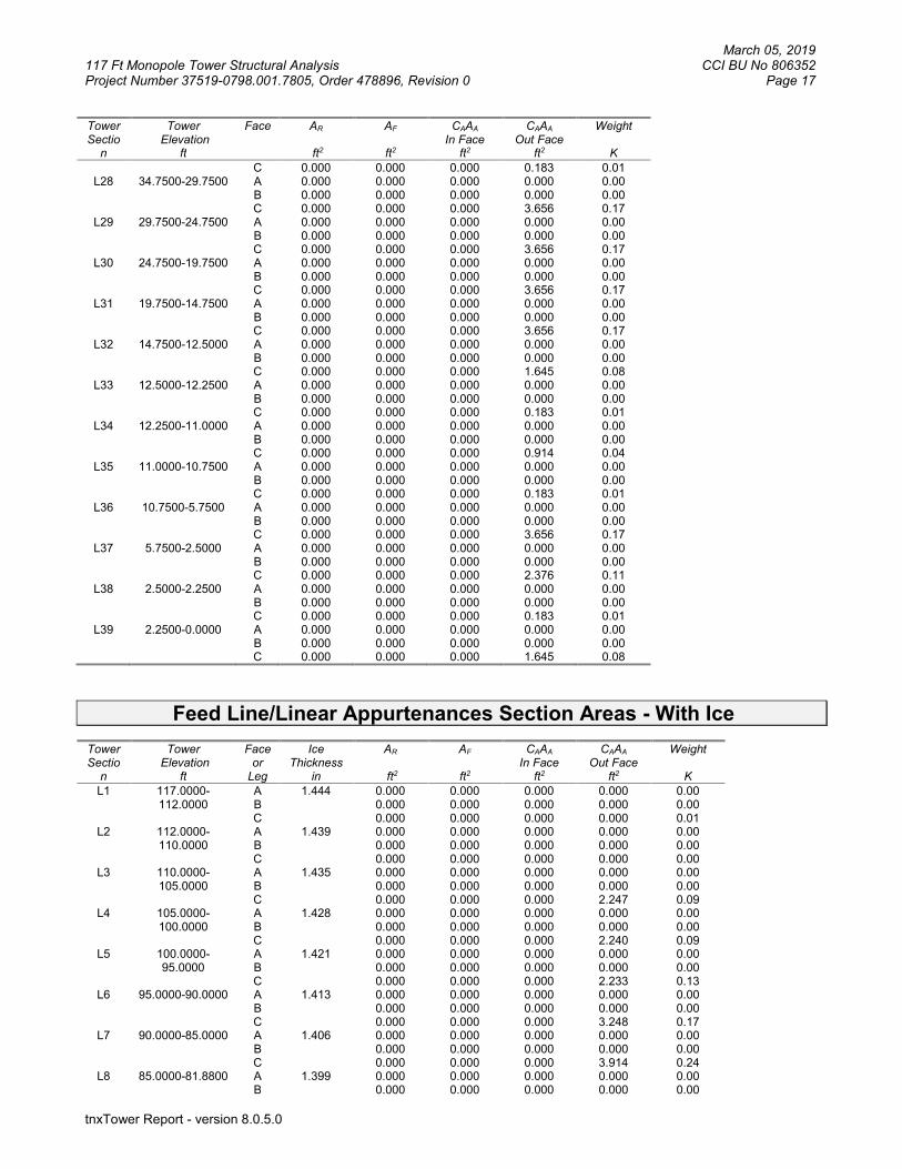
March 05, 2019 117 Ft Monopole Tower Structural Analysis CCI BU No 806352 Project Number 37519-0798.001.7805, Order 478896, Revision 0 Page 17
tnxTower Report - version 8.0.5.0
Tower Sectio
n
Tower Elevation
ft
Face AR
ft2
AF
ft2
CAAA
In Face ft2
CAAA
Out Face ft2
Weight
K
C 0.000 0.000 0.000 0.183 0.01 L28 34.7500-29.7500 A
B C
0.000 0.000 0.000
0.000 0.000 0.000
0.000 0.000 0.000
0.000 0.000 3.656
0.00 0.00 0.17
L29 29.7500-24.7500 A B C
0.000 0.000 0.000
0.000 0.000 0.000
0.000 0.000 0.000
0.000 0.000 3.656
0.00 0.00 0.17
L30 24.7500-19.7500 A B C
0.000 0.000 0.000
0.000 0.000 0.000
0.000 0.000 0.000
0.000 0.000 3.656
0.00 0.00 0.17
L31 19.7500-14.7500 A B C
0.000 0.000 0.000
0.000 0.000 0.000
0.000 0.000 0.000
0.000 0.000 3.656
0.00 0.00 0.17
L32 14.7500-12.5000 A B C
0.000 0.000 0.000
0.000 0.000 0.000
0.000 0.000 0.000
0.000 0.000 1.645
0.00 0.00 0.08
L33 12.5000-12.2500 A B C
0.000 0.000 0.000
0.000 0.000 0.000
0.000 0.000 0.000
0.000 0.000 0.183
0.00 0.00 0.01
L34 12.2500-11.0000 A B C
0.000 0.000 0.000
0.000 0.000 0.000
0.000 0.000 0.000
0.000 0.000 0.914
0.00 0.00 0.04
L35 11.0000-10.7500 A B C
0.000 0.000 0.000
0.000 0.000 0.000
0.000 0.000 0.000
0.000 0.000 0.183
0.00 0.00 0.01
L36 10.7500-5.7500 A B C
0.000 0.000 0.000
0.000 0.000 0.000
0.000 0.000 0.000
0.000 0.000 3.656
0.00 0.00 0.17
L37 5.7500-2.5000 A B C
0.000 0.000 0.000
0.000 0.000 0.000
0.000 0.000 0.000
0.000 0.000 2.376
0.00 0.00 0.11
L38 2.5000-2.2500 A B C
0.000 0.000 0.000
0.000 0.000 0.000
0.000 0.000 0.000
0.000 0.000 0.183
0.00 0.00 0.01
L39 2.2500-0.0000 A B C
0.000 0.000 0.000
0.000 0.000 0.000
0.000 0.000 0.000
0.000 0.000 1.645
0.00 0.00 0.08
Feed Line/Linear Appurtenances Section Areas - With Ice Tower Sectio
n
Tower Elevation
ft
Face or
Leg
Ice Thickness
in
AR
ft2
AF
ft2
CAAA
In Face ft2
CAAA
Out Face ft2
Weight
K
L1 117.0000-112.0000
A B C
1.444 0.000 0.000 0.000
0.000 0.000 0.000
0.000 0.000 0.000
0.000 0.000 0.000
0.00 0.00 0.01
L2 112.0000-110.0000
A B C
1.439 0.000 0.000 0.000
0.000 0.000 0.000
0.000 0.000 0.000
0.000 0.000 0.000
0.00 0.00 0.00
L3 110.0000-105.0000
A B C
1.435 0.000 0.000 0.000
0.000 0.000 0.000
0.000 0.000 0.000
0.000 0.000 2.247
0.00 0.00 0.09
L4 105.0000-100.0000
A B C
1.428 0.000 0.000 0.000
0.000 0.000 0.000
0.000 0.000 0.000
0.000 0.000 2.240
0.00 0.00 0.09
L5 100.0000-95.0000
A B C
1.421 0.000 0.000 0.000
0.000 0.000 0.000
0.000 0.000 0.000
0.000 0.000 2.233
0.00 0.00 0.13
L6 95.0000-90.0000 A B C
1.413 0.000 0.000 0.000
0.000 0.000 0.000
0.000 0.000 0.000
0.000 0.000 3.248
0.00 0.00 0.17
L7 90.0000-85.0000 A B C
1.406 0.000 0.000 0.000
0.000 0.000 0.000
0.000 0.000 0.000
0.000 0.000 3.914
0.00 0.00 0.24
L8 85.0000-81.8800 A B
1.399 0.000 0.000
0.000 0.000
0.000 0.000
0.000 0.000
0.00 0.00

March 05, 2019 117 Ft Monopole Tower Structural Analysis CCI BU No 806352 Project Number 37519-0798.001.7805, Order 478896, Revision 0 Page 18
tnxTower Report - version 8.0.5.0
Tower Sectio
n
Tower Elevation
ft
Face or
Leg
Ice Thickness
in
AR
ft2
AF
ft2
CAAA
In Face ft2
CAAA
Out Face ft2
Weight
K
C 0.000 0.000 0.000 3.756 0.24 L9 81.8800-81.6300 A
B C
1.396 0.000 0.000 0.000
0.000 0.000 0.000
0.000 0.000 0.000
0.000 0.000 0.351
0.00 0.00 0.02
L10 81.6300-76.6300 A B C
1.391 0.000 0.000 0.000
0.000 0.000 0.000
0.000 0.000 0.000
0.000 0.000 7.192
0.00 0.00 0.45
L11 76.6300-76.0800 A B C
1.387 0.000 0.000 0.000
0.000 0.000 0.000
0.000 0.000 0.000
0.000 0.000 1.006
0.00 0.00 0.05
L12 76.0800-75.8300 A B C
1.386 0.000 0.000 0.000
0.000 0.000 0.000
0.000 0.000 0.000
0.000 0.000 0.457
0.00 0.00 0.02
L13 75.8300-71.0000 A B C
1.381 0.000 0.000 0.000
0.000 0.000 0.000
0.000 0.000 0.000
0.000 0.000 8.878
0.00 0.00 0.44
L14 71.0000-70.7500 A B C
1.376 0.000 0.000 0.000
0.000 0.000 0.000
0.000 0.000 0.000
0.000 0.000 0.466
0.00 0.00 0.02
L15 70.7500-68.0800 A B C
1.373 0.000 0.000 0.000
0.000 0.000 0.000
0.000 0.000 0.000
0.000 0.000 4.967
0.00 0.00 0.24
L16 68.0800-67.8300 A B C
1.371 0.000 0.000 0.000
0.000 0.000 0.000
0.000 0.000 0.000
0.000 0.000 0.465
0.00 0.00 0.02
L17 67.8300-63.5000 A B C
1.366 0.000 0.000 0.000
0.000 0.000 0.000
0.000 0.000 0.000
0.000 0.000 8.028
0.00 0.00 0.39
L18 63.5000-63.2500 A B C
1.361 0.000 0.000 0.000
0.000 0.000 0.000
0.000 0.000 0.000
0.000 0.000 0.463
0.00 0.00 0.02
L19 63.2500-58.2500 A B C
1.355 0.000 0.000 0.000
0.000 0.000 0.000
0.000 0.000 0.000
0.000 0.000 9.227
0.00 0.00 0.44
L20 58.2500-53.2500 A B C
1.344 0.000 0.000 0.000
0.000 0.000 0.000
0.000 0.000 0.000
0.000 0.000 9.180
0.00 0.00 0.44
L21 53.2500-47.4200 A B C
1.330 0.000 0.000 0.000
0.000 0.000 0.000
0.000 0.000 0.000
0.000 0.000 10.638
0.00 0.00 0.51
L22 47.4200-46.4200 A B C
1.321 0.000 0.000 0.000
0.000 0.000 0.000
0.000 0.000 0.000
0.000 0.000 1.825
0.00 0.00 0.09
L23 46.4200-41.4200 A B C
1.312 0.000 0.000 0.000
0.000 0.000 0.000
0.000 0.000 0.000
0.000 0.000 9.049
0.00 0.00 0.43
L24 41.4200-38.0800 A B C
1.299 0.000 0.000 0.000
0.000 0.000 0.000
0.000 0.000 0.000
0.000 0.000 6.009
0.00 0.00 0.28
L25 38.0800-37.8300 A B C
1.293 0.000 0.000 0.000
0.000 0.000 0.000
0.000 0.000 0.000
0.000 0.000 0.449
0.00 0.00 0.02
L26 37.8300-35.0000 A B C
1.288 0.000 0.000 0.000
0.000 0.000 0.000
0.000 0.000 0.000
0.000 0.000 5.065
0.00 0.00 0.24
L27 35.0000-34.7500 A B C
1.282 0.000 0.000 0.000
0.000 0.000 0.000
0.000 0.000 0.000
0.000 0.000 0.446
0.00 0.00 0.02
L28 34.7500-29.7500 A B C
1.272 0.000 0.000 0.000
0.000 0.000 0.000
0.000 0.000 0.000
0.000 0.000 8.885
0.00 0.00 0.42
L29 29.7500-24.7500 A B C
1.251 0.000 0.000 0.000
0.000 0.000 0.000
0.000 0.000 0.000
0.000 0.000 8.798
0.00 0.00 0.41
L30 24.7500-19.7500 A B C
1.226 0.000 0.000 0.000
0.000 0.000 0.000
0.000 0.000 0.000
0.000 0.000 8.695
0.00 0.00 0.40
L31 19.7500-14.7500 A B
1.195 0.000 0.000
0.000 0.000
0.000 0.000
0.000 0.000
0.00 0.00

March 05, 2019 117 Ft Monopole Tower Structural Analysis CCI BU No 806352 Project Number 37519-0798.001.7805, Order 478896, Revision 0 Page 19
tnxTower Report - version 8.0.5.0
Tower Sectio
n
Tower Elevation
ft
Face or
Leg
Ice Thickness
in
AR
ft2
AF
ft2
CAAA
In Face ft2
CAAA
Out Face ft2
Weight
K
C 0.000 0.000 0.000 8.568 0.40 L32 14.7500-12.5000 A
B C
1.167 0.000 0.000 0.000
0.000 0.000 0.000
0.000 0.000 0.000
0.000 0.000 3.804
0.00 0.00 0.17
L33 12.5000-12.2500 A B C
1.156 0.000 0.000 0.000
0.000 0.000 0.000
0.000 0.000 0.000
0.000 0.000 0.420
0.00 0.00 0.02
L34 12.2500-11.0000 A B C
1.149 0.000 0.000 0.000
0.000 0.000 0.000
0.000 0.000 0.000
0.000 0.000 2.095
0.00 0.00 0.10
L35 11.0000-10.7500 A B C
1.141 0.000 0.000 0.000
0.000 0.000 0.000
0.000 0.000 0.000
0.000 0.000 0.417
0.00 0.00 0.02
L36 10.7500-5.7500 A B C
1.110 0.000 0.000 0.000
0.000 0.000 0.000
0.000 0.000 0.000
0.000 0.000 8.218
0.00 0.00 0.37
L37 5.7500-2.5000 A B C
1.035 0.000 0.000 0.000
0.000 0.000 0.000
0.000 0.000 0.000
0.000 0.000 5.143
0.00 0.00 0.23
L38 2.5000-2.2500 A B C
0.980 0.000 0.000 0.000
0.000 0.000 0.000
0.000 0.000 0.000
0.000 0.000 0.384
0.00 0.00 0.02
L39 2.2500-0.0000 A B C
0.909 0.000 0.000 0.000
0.000 0.000 0.000
0.000 0.000 0.000
0.000 0.000 3.327
0.00 0.00 0.14
Feed Line Center of Pressure
Section Elevation
ft
CPX
in
CPZ
in
CPX
Ice in
CPZ
Ice in
L1 117.0000-112.0000
0.0000 0.0000 0.0000 0.0000
L2 112.0000-110.0000
0.0000 0.0000 0.0000 0.0000
L3 110.0000-105.0000
-0.7691 0.4440 -1.3173 0.7605
L4 105.0000-100.0000
-0.7743 0.4470 -1.3404 0.7739
L5 100.0000-95.0000 -0.7797 0.4501 -1.3619 0.7863 L6 95.0000-90.0000 -0.9352 0.5400 -1.8822 1.0867 L7 90.0000-85.0000 -1.0364 0.5984 -2.2044 1.2727 L8 85.0000-81.8800 -1.9265 1.1123 -3.0573 1.7651 L9 81.8800-81.6300 -2.2878 1.3209 -3.4035 1.9650
L10 81.6300-76.6300 -2.3379 1.3498 -3.5014 2.0216 L11 76.6300-76.0800 -2.6930 1.5548 -4.1128 2.3745 L12 76.0800-75.8300 -2.6987 1.5581 -4.1228 2.3803 L13 75.8300-71.0000 -2.7534 1.5897 -4.1816 2.4143 L14 71.0000-70.7500 -2.8586 1.6504 -4.2678 2.4640 L15 70.7500-68.0800 -2.8680 1.6558 -4.2900 2.4768 L16 68.0800-67.8300 -2.8790 1.6622 -4.3138 2.4906 L17 67.8300-63.5000 -2.8929 1.6702 -4.3467 2.5095 L18 63.5000-63.2500 -2.9131 1.6819 -4.3860 2.5323 L19 63.2500-58.2500 -2.9274 1.6901 -4.4203 2.5520 L20 58.2500-53.2500 -2.9553 1.7062 -4.4835 2.5886 L21 53.2500-47.4200 -2.9843 1.7230 -4.5466 2.6250 L22 47.4200-46.4200 -2.9913 1.7270 -4.5648 2.6355 L23 46.4200-41.4200 -3.0059 1.7355 -4.5845 2.6469 L24 41.4200-38.0800 -3.0259 1.7470 -4.6239 2.6696 L25 38.0800-37.8300 -3.0331 1.7512 -4.6381 2.6778 L26 37.8300-35.0000 -3.0400 1.7551 -4.6505 2.6850 L27 35.0000-34.7500 -3.0495 1.7606 -4.6658 2.6938 L28 34.7500-29.7500 -3.0609 1.7672 -4.6845 2.7046 L29 29.7500-24.7500 -3.0816 1.7792 -4.7141 2.7217 L30 24.7500-19.7500 -3.1016 1.7907 -4.7346 2.7335
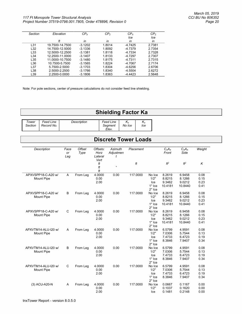
March 05, 2019 117 Ft Monopole Tower Structural Analysis CCI BU No 806352 Project Number 37519-0798.001.7805, Order 478896, Revision 0 Page 20
tnxTower Report - version 8.0.5.0
Section Elevation
ft
CPX
in
CPZ
in
CPX
Ice in
CPZ
Ice in
L31 19.7500-14.7500 -3.1202 1.8014 -4.7425 2.7381 L32 14.7500-12.5000 -3.1336 1.8092 -4.7379 2.7354 L33 12.5000-12.2500 -3.1381 1.8118 -4.7334 2.7328 L34 12.2500-11.0000 -3.1407 1.8133 -4.7297 2.7307 L35 11.0000-10.7500 -3.1480 1.8175 -4.7311 2.7315 L36 10.7500-5.7500 -3.1565 1.8224 -4.7067 2.7174 L37 5.7500-2.5000 -3.1703 1.8304 -4.6256 2.6706 L38 2.5000-2.2500 -3.1766 1.8340 -4.5504 2.6272 L39 2.2500-0.0000 -3.1806 1.8363 -4.4423 2.5648
Note: For pole sections, center of pressure calculations do not consider feed line shielding.
Shielding Factor Ka
Tower Section
Feed Line Record No.
Description Feed Line Segment
Elev.
Ka No Ice
Ka Ice
Discrete Tower Loads
Description Face or
Leg
Offset Type
Offsets: Horz
Lateral Vert
ft ft ft
Azimuth Adjustmen
t °
Placement
ft
CAAA Front
ft2
CAAA Side
ft2
Weight
K
APXVSPP18-C-A20 w/ Mount Pipe
A From Leg 4.0000 0.00 2.00
0.00 117.0000 No Ice 1/2'' Ice
1'' Ice 2'' Ice
8.2619 8.8215 9.3462
10.4181
6.9458 8.1266 9.0212
10.8440
0.08 0.15 0.23 0.41
APXVSPP18-C-A20 w/ Mount Pipe
B From Leg 4.0000 0.00 2.00
0.00 117.0000 No Ice 1/2'' Ice
1'' Ice 2'' Ice
8.2619 8.8215 9.3462
10.4181
6.9458 8.1266 9.0212
10.8440
0.08 0.15 0.23 0.41
APXVSPP18-C-A20 w/ Mount Pipe
C From Leg 4.0000 0.00 2.00
0.00 117.0000 No Ice 1/2'' Ice
1'' Ice 2'' Ice
8.2619 8.8215 9.3462
10.4181
6.9458 8.1266 9.0212
10.8440
0.08 0.15 0.23 0.41
APXVTM14-ALU-I20 w/ Mount Pipe
A From Leg 4.0000 0.00 2.00
0.00 117.0000 No Ice 1/2'' Ice
1'' Ice 2'' Ice
6.5799 7.0306 7.4733 8.3846
4.9591 5.7544 6.4723 7.9407
0.08 0.13 0.19 0.34
APXVTM14-ALU-I20 w/ Mount Pipe
B From Leg 4.0000 0.00 2.00
0.00 117.0000 No Ice 1/2'' Ice
1'' Ice 2'' Ice
6.5799 7.0306 7.4733 8.3846
4.9591 5.7544 6.4723 7.9407
0.08 0.13 0.19 0.34
APXVTM14-ALU-I20 w/ Mount Pipe
C From Leg 4.0000 0.00 2.00
0.00 117.0000 No Ice 1/2'' Ice
1'' Ice 2'' Ice
6.5799 7.0306 7.4733 8.3846
4.9591 5.7544 6.4723 7.9407
0.08 0.13 0.19 0.34
(3) ACU-A20-N A From Leg 4.0000 0.00 2.00
0.00 117.0000 No Ice 1/2'' Ice
0.0667 0.1037 0.1481
0.1167 0.1620 0.2148
0.00 0.00 0.00

March 05, 2019 117 Ft Monopole Tower Structural Analysis CCI BU No 806352 Project Number 37519-0798.001.7805, Order 478896, Revision 0 Page 21
tnxTower Report - version 8.0.5.0
Description Face or
Leg
Offset Type
Offsets: Horz
Lateral Vert
ft ft ft
Azimuth Adjustmen
t °
Placement
ft
CAAA Front
ft2
CAAA Side
ft2
Weight
K
1'' Ice 2'' Ice
0.2593 0.3426 0.01
(3) ACU-A20-N B From Leg 4.0000 0.00 2.00
0.00 117.0000 No Ice 1/2'' Ice
1'' Ice 2'' Ice
0.0667 0.1037 0.1481 0.2593
0.1167 0.1620 0.2148 0.3426
0.00 0.00 0.00 0.01
(3) ACU-A20-N C From Leg 4.0000 0.00 2.00
0.00 117.0000 No Ice 1/2'' Ice
1'' Ice 2'' Ice
0.0667 0.1037 0.1481 0.2593
0.1167 0.1620 0.2148 0.3426
0.00 0.00 0.00 0.01
TD-RRH8x20-25 A From Leg 4.0000 0.00 2.00
0.00 117.0000 No Ice 1/2'' Ice
1'' Ice 2'' Ice
4.0455 4.2975 4.5570 5.0981
1.5345 1.7142 1.9008 2.2951
0.07 0.10 0.13 0.20
TD-RRH8x20-25 B From Leg 4.0000 0.00 2.00
0.00 117.0000 No Ice 1/2'' Ice
1'' Ice 2'' Ice
4.0455 4.2975 4.5570 5.0981
1.5345 1.7142 1.9008 2.2951
0.07 0.10 0.13 0.20
TD-RRH8x20-25 C From Face 4.0000 0.00 2.00
0.00 117.0000 No Ice 1/2'' Ice
1'' Ice 2'' Ice
4.0455 4.2975 4.5570 5.0981
1.5345 1.7142 1.9008 2.2951
0.07 0.10 0.13 0.20
T-Arm Mount [TA 702-3] C None 0.00 117.0000 No Ice 1/2'' Ice
1'' Ice 2'' Ice
5.6400 6.5500 7.4600 9.2800
5.6400 6.5500 7.4600 9.2800
0.34 0.43 0.52 0.70
Stabalizer Bars C None 0.00 117.0000 No Ice 1/2'' Ice
1'' Ice 2'' Ice
2.6100 3.7000 4.7900 6.9700
2.6100 3.7000 4.7900 6.9700
0.04 0.05 0.06 0.08
**** 800 EXTERNAL NOTCH
FILTER A From Leg 2.0000
0.00 0.00
0.00 115.0000 No Ice 1/2'' Ice
1'' Ice 2'' Ice
0.6601 0.7627 0.8727 1.1149
0.3211 0.3983 0.4830 0.6744
0.01 0.02 0.02 0.04
800 EXTERNAL NOTCH FILTER
B From Leg 2.0000 0.00 0.00
0.00 115.0000 No Ice 1/2'' Ice
1'' Ice 2'' Ice
0.6601 0.7627 0.8727 1.1149
0.3211 0.3983 0.4830 0.6744
0.01 0.02 0.02 0.04
800 EXTERNAL NOTCH FILTER
C From Leg 2.0000 0.00 0.00
0.00 115.0000 No Ice 1/2'' Ice
1'' Ice 2'' Ice
0.6601 0.7627 0.8727 1.1149
0.3211 0.3983 0.4830 0.6744
0.01 0.02 0.02 0.04
TME-PCS 1900MHz 4x45W-65MHz
A From Leg 2.0000 0.00 0.00
0.00 115.0000 No Ice 1/2'' Ice
1'' Ice 2'' Ice
2.3218 2.5266 2.7388 3.1855
2.2381 2.4407 2.6507 3.0929
0.06 0.08 0.11 0.17
TME-PCS 1900MHz 4x45W-65MHz
B From Leg 2.0000 0.00 0.00
0.00 115.0000 No Ice 1/2'' Ice
1'' Ice 2'' Ice
2.3218 2.5266 2.7388 3.1855
2.2381 2.4407 2.6507 3.0929
0.06 0.08 0.11 0.17
TME-PCS 1900MHz 4x45W-65MHz
C From Leg 2.0000 0.00
0.00 115.0000 No Ice 1/2''
2.3218 2.5266
2.2381 2.4407
0.06 0.08

March 05, 2019 117 Ft Monopole Tower Structural Analysis CCI BU No 806352 Project Number 37519-0798.001.7805, Order 478896, Revision 0 Page 22
tnxTower Report - version 8.0.5.0
Description Face or
Leg
Offset Type
Offsets: Horz
Lateral Vert
ft ft ft
Azimuth Adjustmen
t °
Placement
ft
CAAA Front
ft2
CAAA Side
ft2
Weight
K
0.00 Ice 1'' Ice 2'' Ice
2.7388 3.1855
2.6507 3.0929
0.11 0.17
TME-800MHZ RRH A From Leg 2.0000 0.00 0.00
0.00 115.0000 No Ice 1/2'' Ice
1'' Ice 2'' Ice
2.1342 2.3195 2.5123 2.9201
1.7730 1.9461 2.1267 2.5100
0.05 0.07 0.10 0.16
TME-800MHZ RRH B From Leg 2.0000 0.00 0.00
0.00 115.0000 No Ice 1/2'' Ice
1'' Ice 2'' Ice
2.1342 2.3195 2.5123 2.9201
1.7730 1.9461 2.1267 2.5100
0.05 0.07 0.10 0.16
TME-800MHZ RRH C From Leg 2.0000 0.00 0.00
0.00 115.0000 No Ice 1/2'' Ice
1'' Ice 2'' Ice
2.1342 2.3195 2.5123 2.9201
1.7730 1.9461 2.1267 2.5100
0.05 0.07 0.10 0.16
Side Arm Mount [SO 102-3]
C None 0.00 115.0000 No Ice 1/2'' Ice
1'' Ice 2'' Ice
3.0000 3.4800 3.9600 4.9200
3.0000 3.4800 3.9600 4.9200
0.08 0.11 0.14 0.20
*** ERICSSON AIR 21 B2A
B4P w/ Mount Pipe A From Leg 1.0000
0.00 2.00
0.00 110.0000 No Ice 1/2'' Ice
1'' Ice 2'' Ice
6.3292 6.7751 7.2137 8.1168
5.6424 6.4259 7.1313 8.5907
0.11 0.17 0.23 0.38
ERICSSON AIR 21 B2A B4P w/ Mount Pipe
B From Leg 1.0000 0.00 2.00
0.00 110.0000 No Ice 1/2'' Ice
1'' Ice 2'' Ice
6.3292 6.7751 7.2137 8.1168
5.6424 6.4259 7.1313 8.5907
0.11 0.17 0.23 0.38
ERICSSON AIR 21 B2A B4P w/ Mount Pipe
C From Leg 1.0000 0.00 2.00
0.00 110.0000 No Ice 1/2'' Ice
1'' Ice 2'' Ice
6.3292 6.7751 7.2137 8.1168
5.6424 6.4259 7.1313 8.5907
0.11 0.17 0.23 0.38
KRY 112 144/1 A From Leg 1.0000 0.00 2.00
0.00 110.0000 No Ice 1/2'' Ice
1'' Ice 2'' Ice
0.3500 0.4259 0.5093 0.6981
0.1750 0.2343 0.3009 0.4565
0.01 0.01 0.02 0.03
KRY 112 144/1 B From Leg 1.0000 0.00 2.00
0.00 110.0000 No Ice 1/2'' Ice
1'' Ice 2'' Ice
0.3500 0.4259 0.5093 0.6981
0.1750 0.2343 0.3009 0.4565
0.01 0.01 0.02 0.03
KRY 112 144/1 B From Leg 1.0000 0.00 2.00
0.00 110.0000 No Ice 1/2'' Ice
1'' Ice 2'' Ice
0.3500 0.4259 0.5093 0.6981
0.1750 0.2343 0.3009 0.4565
0.01 0.01 0.02 0.03
Ericsson Air 21 B4A B12P-B8P 4FT w/ Mount Pipe
A From Leg 4.0000 0.00 2.00
0.00 110.0000 No Ice 1/2'' Ice
1'' Ice 2'' Ice
7.8625 8.3076 8.7610 9.6925
6.8796 7.5944 8.3255 9.8364
0.16 0.23 0.31 0.49
Ericsson Air 21 B4A B12P-B8P 4FT w/ Mount Pipe
B From Leg 4.0000 0.00 2.00
0.00 110.0000 No Ice 1/2'' Ice
1'' Ice 2'' Ice
7.8625 8.3076 8.7610 9.6925
6.8796 7.5944 8.3255 9.8364
0.16 0.23 0.31 0.49
Ericsson Air 21 B4A B12P- C From Leg 4.0000 0.00 110.0000 No Ice 7.8625 6.8796 0.16

March 05, 2019 117 Ft Monopole Tower Structural Analysis CCI BU No 806352 Project Number 37519-0798.001.7805, Order 478896, Revision 0 Page 23
tnxTower Report - version 8.0.5.0
Description Face or
Leg
Offset Type
Offsets: Horz
Lateral Vert
ft ft ft
Azimuth Adjustmen
t °
Placement
ft
CAAA Front
ft2
CAAA Side
ft2
Weight
K
B8P 4FT w/ Mount Pipe 0.00 2.00
1/2'' Ice
1'' Ice 2'' Ice
8.3076 8.7610 9.6925
7.5944 8.3255 9.8364
0.23 0.31 0.49
RRUS 11 B12 A From Leg 4.0000 0.00 2.00
0.00 110.0000 No Ice 1/2'' Ice
1'' Ice 2'' Ice
2.8333 3.0426 3.2593 3.7148
1.1821 1.3299 1.4848 1.8259
0.05 0.07 0.10 0.15
RRUS 11 B12 B From Leg 4.0000 0.00 2.00
0.00 110.0000 No Ice 1/2'' Ice
1'' Ice 2'' Ice
2.8333 3.0426 3.2593 3.7148
1.1821 1.3299 1.4848 1.8259
0.05 0.07 0.10 0.15
RRUS 11 B12 C From Leg 4.0000 0.00 2.00
0.00 110.0000 No Ice 1/2'' Ice
1'' Ice 2'' Ice
2.8333 3.0426 3.2593 3.7148
1.1821 1.3299 1.4848 1.8259
0.05 0.07 0.10 0.15
T-Arm Mount [TA 602-3] C None 0.00 110.0000 No Ice 1/2'' Ice
1'' Ice 2'' Ice
11.5900 15.4400 19.2900 26.9900
11.5900 15.4400 19.2900 26.9900
0.77 0.99 1.21 1.64
(2) 2.375'' OD x 4' Mount Pipe
A From Leg 4.0000 0.00 0.00
0.00 110.0000 No Ice 1/2'' Ice
1'' Ice 2'' Ice
0.8657 1.1106 1.3648 1.9008
0.8657 1.1106 1.3648 1.9008
0.02 0.03 0.04 0.06
(2) 2.375'' OD x 4' Mount Pipe
B From Leg 4.0000 0.00 0.00
0.00 110.0000 No Ice 1/2'' Ice
1'' Ice 2'' Ice
0.8657 1.1106 1.3648 1.9008
0.8657 1.1106 1.3648 1.9008
0.02 0.03 0.04 0.06
(2) 2.375'' OD x 4' Mount Pipe
C From Leg 4.0000 0.00 0.00
0.00 110.0000 No Ice 1/2'' Ice
1'' Ice 2'' Ice
0.8657 1.1106 1.3648 1.9008
0.8657 1.1106 1.3648 1.9008
0.02 0.03 0.04 0.06
*** (2) HBXX-6516DS-A2M w/
Mount Pipe A From Leg 4.0000
0.00 1.00
0.00 100.0000 No Ice 1/2'' Ice
1'' Ice 2'' Ice
6.6672 7.5501 8.4493 9.8792
5.5365 6.8440 8.1652
10.1139
0.07 0.13 0.19 0.35
(2) HBXX-6516DS-A2M w/ Mount Pipe
B From Leg 4.0000 0.00 1.00
0.00 100.0000 No Ice 1/2'' Ice
1'' Ice 2'' Ice
6.6672 7.5501 8.4493 9.8792
5.5365 6.8440 8.1652
10.1139
0.07 0.13 0.19 0.35
(2) HBXX-6516DS-A2M w/ Mount Pipe
C From Leg 4.0000 0.00 1.00
0.00 100.0000 No Ice 1/2'' Ice
1'' Ice 2'' Ice
6.6672 7.5501 8.4493 9.8792
5.5365 6.8440 8.1652
10.1139
0.07 0.13 0.19 0.35
800 10735V01 w/ Mount Pipe
A From Leg 4.0000 0.00 1.00
0.00 100.0000 No Ice 1/2'' Ice
1'' Ice 2'' Ice
8.8727 9.4550
10.0100 11.1272
5.4888 6.7103 7.6880 9.5633
0.06 0.12 0.19 0.36
800 10735V01 w/ Mount Pipe
B From Leg 4.0000 0.00 1.00
0.00 100.0000 No Ice 1/2'' Ice
1'' Ice 2'' Ice
8.8727 9.4550
10.0100 11.1272
5.4888 6.7103 7.6880 9.5633
0.06 0.12 0.19 0.36

March 05, 2019 117 Ft Monopole Tower Structural Analysis CCI BU No 806352 Project Number 37519-0798.001.7805, Order 478896, Revision 0 Page 24
tnxTower Report - version 8.0.5.0
Description Face or
Leg
Offset Type
Offsets: Horz
Lateral Vert
ft ft ft
Azimuth Adjustmen
t °
Placement
ft
CAAA Front
ft2
CAAA Side
ft2
Weight
K
800 10735V01 w/ Mount Pipe
C From Leg 4.0000 0.00 1.00
0.00 100.0000 No Ice 1/2'' Ice
1'' Ice 2'' Ice
8.8727 9.4550
10.0100 11.1272
5.4888 6.7103 7.6880 9.5633
0.06 0.12 0.19 0.36
(2) DB844G65ZAXY w/ Mount Pipe
A From Leg 4.0000 0.00 1.00
0.00 100.0000 No Ice 1/2'' Ice
1'' Ice 2'' Ice
4.5782 4.9555 5.3404 6.1369
4.8023 5.4160 6.0401 7.3370
0.03 0.08 0.13 0.26
(2) DB844G65ZAXY w/ Mount Pipe
B From Leg 4.0000 0.00 1.00
0.00 100.0000 No Ice 1/2'' Ice
1'' Ice 2'' Ice
4.5782 4.9555 5.3404 6.1369
4.8023 5.4160 6.0401 7.3370
0.03 0.08 0.13 0.26
(2) DB844G65ZAXY w/ Mount Pipe
C From Leg 4.0000 0.00 1.00
0.00 100.0000 No Ice 1/2'' Ice
1'' Ice 2'' Ice
4.5782 4.9555 5.3404 6.1369
4.8023 5.4160 6.0401 7.3370
0.03 0.08 0.13 0.26
(2) FD9R6004/2C-3L A From Leg 4.0000 0.00 1.00
0.00 100.0000 No Ice 1/2'' Ice
1'' Ice 2'' Ice
0.3142 0.3862 0.4656 0.6468
0.0762 0.1189 0.1685 0.2940
0.00 0.01 0.01 0.02
(2) FD9R6004/2C-3L B From Leg 4.0000 0.00 1.00
0.00 100.0000 No Ice 1/2'' Ice
1'' Ice 2'' Ice
0.3142 0.3862 0.4656 0.6468
0.0762 0.1189 0.1685 0.2940
0.00 0.01 0.01 0.02
(2) FD9R6004/2C-3L C From Leg 4.0000 0.00 1.00
0.00 100.0000 No Ice 1/2'' Ice
1'' Ice 2'' Ice
0.3142 0.3862 0.4656 0.6468
0.0762 0.1189 0.1685 0.2940
0.00 0.01 0.01 0.02
B4 RRH2X60-4R A From Leg 4.0000 0.00 1.00
0.00 100.0000 No Ice 1/2'' Ice
1'' Ice 2'' Ice
3.3554 3.6120 3.8757 4.4240
2.0048 2.2369 2.4759 2.9750
0.06 0.08 0.11 0.18
B4 RRH2X60-4R B From Leg 4.0000 0.00 1.00
0.00 100.0000 No Ice 1/2'' Ice
1'' Ice 2'' Ice
3.3554 3.6120 3.8757 4.4240
2.0048 2.2369 2.4759 2.9750
0.06 0.08 0.11 0.18
B4 RRH2X60-4R C From Leg 4.0000 0.00 1.00
0.00 100.0000 No Ice 1/2'' Ice
1'' Ice 2'' Ice
3.3554 3.6120 3.8757 4.4240
2.0048 2.2369 2.4759 2.9750
0.06 0.08 0.11 0.18
B13 RRH 4X30 A From Leg 4.0000 0.00 1.00
0.00 100.0000 No Ice 1/2'' Ice
1'' Ice 2'' Ice
2.0552 2.2405 2.4333 2.8411
1.3201 1.4754 1.6376 1.9966
0.06 0.07 0.09 0.14
B13 RRH 4X30 B From Leg 4.0000 0.00 1.00
0.00 100.0000 No Ice 1/2'' Ice
1'' Ice 2'' Ice
2.0552 2.2405 2.4333 2.8411
1.3201 1.4754 1.6376 1.9966
0.06 0.07 0.09 0.14
B13 RRH 4X30 C From Leg 4.0000 0.00 1.00
0.00 100.0000 No Ice 1/2'' Ice
1'' Ice 2'' Ice
2.0552 2.2405 2.4333 2.8411
1.3201 1.4754 1.6376 1.9966
0.06 0.07 0.09 0.14

March 05, 2019 117 Ft Monopole Tower Structural Analysis CCI BU No 806352 Project Number 37519-0798.001.7805, Order 478896, Revision 0 Page 25
tnxTower Report - version 8.0.5.0
Description Face or
Leg
Offset Type
Offsets: Horz
Lateral Vert
ft ft ft
Azimuth Adjustmen
t °
Placement
ft
CAAA Front
ft2
CAAA Side
ft2
Weight
K
B25 RRH4X30 A From Leg 4.0000 0.00 1.00
0.00 100.0000 No Ice 1/2'' Ice
1'' Ice 2'' Ice
2.2000 2.3926 2.5926 3.0148
1.7417 1.9204 2.1065 2.5009
0.06 0.08 0.10 0.16
B25 RRH4X30 B From Leg 4.0000 0.00 1.00
0.00 100.0000 No Ice 1/2'' Ice
1'' Ice 2'' Ice
2.2000 2.3926 2.5926 3.0148
1.7417 1.9204 2.1065 2.5009
0.06 0.08 0.10 0.16
B25 RRH4X30 C From Leg 4.0000 0.00 1.00
0.00 100.0000 No Ice 1/2'' Ice
1'' Ice 2'' Ice
2.2000 2.3926 2.5926 3.0148
1.7417 1.9204 2.1065 2.5009
0.06 0.08 0.10 0.16
RRFDC-3315-PF-48 A From Leg 4.0000 0.00 1.00
0.00 100.0000 No Ice 1/2'' Ice
1'' Ice 2'' Ice
3.3636 3.5972 3.8383 4.3426
2.1921 2.3950 2.6056 3.0491
0.03 0.06 0.09 0.17
RRFDC-3315-PF-48 C From Leg 4.0000 0.00 1.00
0.00 100.0000 No Ice 1/2'' Ice
1'' Ice 2'' Ice
3.3636 3.5972 3.8383 4.3426
2.1921 2.3950 2.6056 3.0491
0.03 0.06 0.09 0.17
GPS_A C From Leg 4.0000 0.00 4.00
0.00 100.0000 No Ice 1/2'' Ice
1'' Ice 2'' Ice
0.2550 0.3205 0.3934 0.5614
0.2550 0.3205 0.3934 0.5614
0.00 0.00 0.01 0.02
Platform Mount [LP 715-1] C None 0.00 100.0000 No Ice 1/2'' Ice
1'' Ice 2'' Ice
44.2100 53.9700 63.7300 83.2500
44.2100 53.9700 63.7300 83.2500
1.77 2.32 2.87 3.97
*** Pipe Mount [PM 601-3] C None 0.00 93.0000 No Ice
1/2'' Ice
1'' Ice 2'' Ice
4.3900 5.4800 6.5700 8.7500
4.3900 5.4800 6.5700 8.7500
0.20 0.24 0.28 0.36
*** 7770.00 w/ Mount Pipe A From Leg 4.0000
0.00 0.00
0.00 89.0000 No Ice 1/2'' Ice
1'' Ice 2'' Ice
5.7460 6.1791 6.6067 7.4880
4.2543 5.0137 5.7109 7.1553
0.06 0.10 0.16 0.29
7770.00 w/ Mount Pipe B From Leg 4.0000 0.00 0.00
0.00 89.0000 No Ice 1/2'' Ice
1'' Ice 2'' Ice
5.7460 6.1791 6.6067 7.4880
4.2543 5.0137 5.7109 7.1553
0.06 0.10 0.16 0.29
7770.00 w/ Mount Pipe C From Leg 4.0000 0.00 0.00
0.00 89.0000 No Ice 1/2'' Ice
1'' Ice 2'' Ice
5.7460 6.1791 6.6067 7.4880
4.2543 5.0137 5.7109 7.1553
0.06 0.10 0.16 0.29
RRUS 11 A From Leg 4.0000 0.00 0.00
0.00 89.0000 No Ice 1/2'' Ice
1'' Ice 2'' Ice
2.7908 2.9984 3.2134 3.6656
1.1923 1.3395 1.4957 1.8390
0.05 0.07 0.10 0.15
RRUS 11 B From Leg 4.0000 0.00 0.00
0.00 89.0000 No Ice 1/2'' Ice
2.7908 2.9984 3.2134
1.1923 1.3395 1.4957
0.05 0.07 0.10

March 05, 2019 117 Ft Monopole Tower Structural Analysis CCI BU No 806352 Project Number 37519-0798.001.7805, Order 478896, Revision 0 Page 26
tnxTower Report - version 8.0.5.0
Description Face or
Leg
Offset Type
Offsets: Horz
Lateral Vert
ft ft ft
Azimuth Adjustmen
t °
Placement
ft
CAAA Front
ft2
CAAA Side
ft2
Weight
K
1'' Ice 2'' Ice
3.6656 1.8390 0.15
RRUS 11 C From Leg 4.0000 0.00 0.00
0.00 89.0000 No Ice 1/2'' Ice
1'' Ice 2'' Ice
2.7908 2.9984 3.2134 3.6656
1.1923 1.3395 1.4957 1.8390
0.05 0.07 0.10 0.15
DC6-48-60-18-8F A From Leg 4.0000 0.00 0.00
0.00 89.0000 No Ice 1/2'' Ice
1'' Ice 2'' Ice
1.2117 1.8924 2.1051 2.5703
1.2117 1.8924 2.1051 2.5703
0.03 0.05 0.08 0.14
QS66512-2 w/ Mount Pipe A From Leg 4.0000 0.00 0.00
0.00 89.0000 No Ice 1/2'' Ice
1'' Ice 2'' Ice
2.6000 9.2903 9.9098
11.1763
5.0000 9.6573
10.6203 12.6104
0.14 0.21 0.30 0.49
QS66512-2 w/ Mount Pipe B From Leg 4.0000 0.00 0.00
0.00 89.0000 No Ice 1/2'' Ice
1'' Ice 2'' Ice
2.6000 9.2903 9.9098
11.1763
5.0000 9.6573
10.6203 12.6104
0.14 0.21 0.30 0.49
OPA-65R-LCUU-H6 w/ Mount Pipe
A From Leg 4.0000 0.00 0.00
0.00 89.0000 No Ice 1/2'' Ice
1'' Ice 2'' Ice
9.8953 10.4700 11.0098 12.1119
7.1792 8.3621 9.2588
11.0860
0.10 0.18 0.26 0.46
OPA-65R-LCUU-H6 w/ Mount Pipe
B From Leg 4.0000 0.00 0.00
0.00 89.0000 No Ice 1/2'' Ice
1'' Ice 2'' Ice
9.8953 10.4700 11.0098 12.1119
7.1792 8.3621 9.2588
11.0860
0.10 0.18 0.26 0.46
TPA-65R-LCUUUU-H8 w/ Mount Pipe
C From Leg 4.0000 0.00 0.00
0.00 89.0000 No Ice 1/2'' Ice
1'' Ice 2'' Ice
13.5353 14.2380 14.9495 16.3081
10.9597 12.4861 14.0367 16.3910
0.11 0.22 0.33 0.59
OPA-65R-LCUU-H8 w/ Mount Pipe
C From Leg 4.0000 0.00 0.00
0.00 89.0000 No Ice 1/2'' Ice
1'' Ice 2'' Ice
12.9838 13.6685 14.3572 15.6789
9.3187 10.7901 12.2416 14.4988
0.12 0.21 0.32 0.56
RRUS 32 B2 A From Leg 4.0000 0.00 0.00
0.00 89.0000 No Ice 1/2'' Ice
1'' Ice 2'' Ice
2.7427 2.9647 3.1941 3.6753
1.6681 1.8552 2.0493 2.4585
0.05 0.07 0.10 0.16
RRUS 32 B2 B From Leg 4.0000 0.00 0.00
0.00 89.0000 No Ice 1/2'' Ice
1'' Ice 2'' Ice
2.7427 2.9647 3.1941 3.6753
1.6681 1.8552 2.0493 2.4585
0.05 0.07 0.10 0.16
RRUS 32 B2 C From Leg 4.0000 0.00 0.00
0.00 89.0000 No Ice 1/2'' Ice
1'' Ice 2'' Ice
2.7427 2.9647 3.1941 3.6753
1.6681 1.8552 2.0493 2.4585
0.05 0.07 0.10 0.16
RRUS 32 B30 A From Leg 4.0000 0.00 0.00
0.00 89.0000 No Ice 1/2'' Ice
1'' Ice 2'' Ice
2.7427 2.9647 3.1941 3.6753
1.6681 1.8552 2.0493 2.4585
0.05 0.07 0.10 0.16
RRUS 32 B30 B From Leg 4.0000 0.00 0.00
0.00 89.0000 No Ice 1/2'' Ice
2.7427 2.9647 3.1941
1.6681 1.8552 2.0493
0.05 0.07 0.10

March 05, 2019 117 Ft Monopole Tower Structural Analysis CCI BU No 806352 Project Number 37519-0798.001.7805, Order 478896, Revision 0 Page 27
tnxTower Report - version 8.0.5.0
Description Face or
Leg
Offset Type
Offsets: Horz
Lateral Vert
ft ft ft
Azimuth Adjustmen
t °
Placement
ft
CAAA Front
ft2
CAAA Side
ft2
Weight
K
1'' Ice 2'' Ice
3.6753 2.4585 0.16
RRUS 32 B30 C From Leg 4.0000 0.00 0.00
0.00 89.0000 No Ice 1/2'' Ice
1'' Ice 2'' Ice
2.7427 2.9647 3.1941 3.6753
1.6681 1.8552 2.0493 2.4585
0.05 0.07 0.10 0.16
(2) TPX-070821 A From Leg 4.0000 0.00 0.00
0.00 89.0000 No Ice 1/2'' Ice
1'' Ice 2'' Ice
0.4688 0.5585 0.6556 0.8721
0.1009 0.1471 0.2020 0.3340
0.01 0.01 0.02 0.03
(2) TPX-070821 B From Leg 4.0000 0.00 0.00
0.00 89.0000 No Ice 1/2'' Ice
1'' Ice 2'' Ice
0.4688 0.5585 0.6556 0.8721
0.1009 0.1471 0.2020 0.3340
0.01 0.01 0.02 0.03
(2) TPX-070821 C From Leg 4.0000 0.00 0.00
0.00 89.0000 No Ice 1/2'' Ice
1'' Ice 2'' Ice
0.4688 0.5585 0.6556 0.8721
0.1009 0.1471 0.2020 0.3340
0.01 0.01 0.02 0.03
DC6-48-60-18-8F A From Leg 4.0000 0.00 0.00
0.00 89.0000 No Ice 1/2'' Ice
1'' Ice 2'' Ice
1.2117 1.8924 2.1051 2.5703
1.2117 1.8924 2.1051 2.5703
0.03 0.05 0.08 0.14
RRUS 4426 B66 A From Leg 4.0000 0.00 0.00
0.00 89.0000 No Ice 1/2'' Ice
1'' Ice 2'' Ice
1.6444 1.8044 1.9719 2.3292
0.7252 0.8421 0.9685 1.2437
0.05 0.06 0.08 0.11
RRUS 4426 B66 B From Leg 4.0000 0.00 0.00
0.00 89.0000 No Ice 1/2'' Ice
1'' Ice 2'' Ice
1.6444 1.8044 1.9719 2.3292
0.7252 0.8421 0.9685 1.2437
0.05 0.06 0.08 0.11
RRUS 4426 B66 C From Leg 4.0000 0.00 0.00
0.00 89.0000 No Ice 1/2'' Ice
1'' Ice 2'' Ice
1.6444 1.8044 1.9719 2.3292
0.7252 0.8421 0.9685 1.2437
0.05 0.06 0.08 0.11
(2) LGP21401 A From Leg 4.0000 0.00 0.00
0.00 89.0000 No Ice 1/2'' Ice
1'' Ice 2'' Ice
1.1040 1.2388 1.3810 1.6877
0.3471 0.4422 0.5444 0.7696
0.01 0.02 0.03 0.05
(2) LGP21401 B From Leg 4.0000 0.00 0.00
0.00 89.0000 No Ice 1/2'' Ice
1'' Ice 2'' Ice
1.1040 1.2388 1.3810 1.6877
0.3471 0.4422 0.5444 0.7696
0.01 0.02 0.03 0.05
(2) LGP21401 C From Leg 4.0000 0.00 0.00
0.00 89.0000 No Ice 1/2'' Ice
1'' Ice 2'' Ice
1.1040 1.2388 1.3810 1.6877
0.3471 0.4422 0.5444 0.7696
0.01 0.02 0.03 0.05
(2) 7020.00 A From Leg 4.0000 0.00 0.00
0.00 89.0000 No Ice 1/2'' Ice
1'' Ice 2'' Ice
0.1021 0.1469 0.1991 0.3258
0.1750 0.2393 0.3109 0.4765
0.00 0.01 0.01 0.02
(2) 7020.00 B From Leg 4.0000 0.00 0.00
0.00 89.0000 No Ice 1/2'' Ice
0.1021 0.1469 0.1991
0.1750 0.2393 0.3109
0.00 0.01 0.01
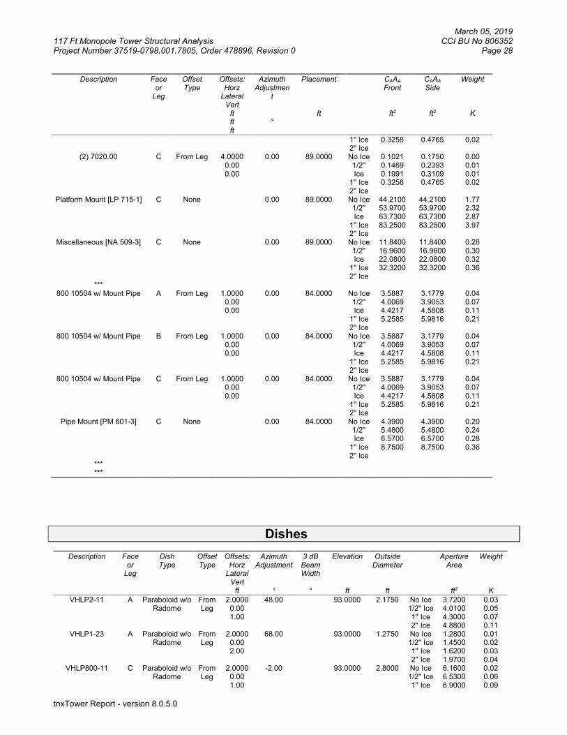
March 05, 2019 117 Ft Monopole Tower Structural Analysis CCI BU No 806352 Project Number 37519-0798.001.7805, Order 478896, Revision 0 Page 28
tnxTower Report - version 8.0.5.0
Description Face or
Leg
Offset Type
Offsets: Horz
Lateral Vert
ft ft ft
Azimuth Adjustmen
t °
Placement
ft
CAAA Front
ft2
CAAA Side
ft2
Weight
K
1'' Ice 2'' Ice
0.3258 0.4765 0.02
(2) 7020.00 C From Leg 4.0000 0.00 0.00
0.00 89.0000 No Ice 1/2'' Ice
1'' Ice 2'' Ice
0.1021 0.1469 0.1991 0.3258
0.1750 0.2393 0.3109 0.4765
0.00 0.01 0.01 0.02
Platform Mount [LP 715-1] C None 0.00 89.0000 No Ice 1/2'' Ice
1'' Ice 2'' Ice
44.2100 53.9700 63.7300 83.2500
44.2100 53.9700 63.7300 83.2500
1.77 2.32 2.87 3.97
Miscellaneous [NA 509-3] C None 0.00 89.0000 No Ice 1/2'' Ice
1'' Ice 2'' Ice
11.8400 16.9600 22.0800 32.3200
11.8400 16.9600 22.0800 32.3200
0.28 0.30 0.32 0.36
*** 800 10504 w/ Mount Pipe A From Leg 1.0000
0.00 0.00
0.00 84.0000 No Ice 1/2'' Ice
1'' Ice 2'' Ice
3.5887 4.0069 4.4217 5.2585
3.1779 3.9053 4.5808 5.9816
0.04 0.07 0.11 0.21
800 10504 w/ Mount Pipe B From Leg 1.0000 0.00 0.00
0.00 84.0000 No Ice 1/2'' Ice
1'' Ice 2'' Ice
3.5887 4.0069 4.4217 5.2585
3.1779 3.9053 4.5808 5.9816
0.04 0.07 0.11 0.21
800 10504 w/ Mount Pipe C From Leg 1.0000 0.00 0.00
0.00 84.0000 No Ice 1/2'' Ice
1'' Ice 2'' Ice
3.5887 4.0069 4.4217 5.2585
3.1779 3.9053 4.5808 5.9816
0.04 0.07 0.11 0.21
Pipe Mount [PM 601-3] C None 0.00 84.0000 No Ice 1/2'' Ice
1'' Ice 2'' Ice
4.3900 5.4800 6.5700 8.7500
4.3900 5.4800 6.5700 8.7500
0.20 0.24 0.28 0.36
*** ***
Dishes
Description Face or
Leg
Dish Type
Offset Type
Offsets: Horz
Lateral Vert
ft
Azimuth Adjustment
°
3 dB Beam Width
°
Elevation
ft
Outside Diameter
ft
Aperture Area
ft2
Weight
K
VHLP2-11 A Paraboloid w/o Radome
From Leg
2.0000 0.00 1.00
48.00 93.0000 2.1750 No Ice 1/2'' Ice 1'' Ice 2'' Ice
3.7200 4.0100 4.3000 4.8800
0.03 0.05 0.07 0.11
VHLP1-23 A Paraboloid w/o Radome
From Leg
2.0000 0.00 2.00
68.00 93.0000 1.2750 No Ice 1/2'' Ice 1'' Ice 2'' Ice
1.2800 1.4500 1.6200 1.9700
0.01 0.02 0.03 0.04
VHLP800-11 C Paraboloid w/o Radome
From Leg
2.0000 0.00 1.00
-2.00 93.0000 2.8000 No Ice 1/2'' Ice 1'' Ice
6.1600 6.5300 6.9000
0.02 0.06 0.09

March 05, 2019 117 Ft Monopole Tower Structural Analysis CCI BU No 806352 Project Number 37519-0798.001.7805, Order 478896, Revision 0 Page 29
tnxTower Report - version 8.0.5.0
Description Face or
Leg
Dish Type
Offset Type
Offsets: Horz
Lateral Vert
ft
Azimuth Adjustment
°
3 dB Beam Width
°
Elevation
ft
Outside Diameter
ft
Aperture Area
ft2
Weight
K
2'' Ice 7.6400 0.17 VHLP1-23 A Paraboloid w/o
Radome From Leg
2.0000 0.00 -1.00
68.00 93.0000 1.2750 No Ice 1/2'' Ice 1'' Ice 2'' Ice
1.2800 1.4500 1.6200 1.9700
0.01 0.02 0.03 0.04
**
Tower Pressures - No Ice
GH = 1.100
Section
Elevation
ft
z
ft
KZ
qz
psf
AG
ft2
F a c e
AF
ft2
AR
ft2
Aleg
ft2
Leg %
CAAA In
Face ft2
CAAA Out
Face ft2
L1 117.0000-112.0000
114.4685 1.302 43.256
6.410 A B C
0.000 0.000 0.000
6.410 6.410 6.410
6.410 100.00 100.00 100.00
0.000 0.000 0.000
0.000 0.000 0.000
L2 112.0000-110.0000
110.9952 1.294 42.976
2.700 A B C
0.000 0.000 0.000
2.700 2.700 2.700
2.700 100.00 100.00 100.00
0.000 0.000 0.000
0.000 0.000 0.000
L3 110.0000-105.0000
107.4715 1.285 42.685
7.092 A B C
0.000 0.000 0.000
7.092 7.092 7.092
7.092 100.00 100.00 100.00
0.000 0.000 0.000
0.000 0.000 0.813
L4 105.0000-100.0000
102.4733 1.272 42.259
7.580 A B C
0.000 0.000 0.000
7.580 7.580 7.580
7.580 100.00 100.00 100.00
0.000 0.000 0.000
0.000 0.000 0.813
L5 100.0000-95.0000
97.4751 1.259 41.817
8.056 A B C
0.000 0.000 0.000
8.056 8.056 8.056
8.056 100.00 100.00 100.00
0.000 0.000 0.000
0.000 0.000 0.813
L6 95.0000-90.0000
92.4765 1.245 41.356
8.540 A B C
0.000 0.000 0.000
8.540 8.540 8.540
8.540 100.00 100.00 100.00
0.000 0.000 0.000
0.000 0.000 0.987
L7 90.0000-85.0000
87.4777 1.23 40.875
9.024 A B C
0.000 0.000 0.000
9.024 9.024 9.024
9.024 100.00 100.00 100.00
0.000 0.000 0.000
0.000 0.000 1.103
L8 85.0000-81.8800
83.4317 1.218 40.469
5.876 A B C
0.000 0.000 0.000
5.876 5.876 5.876
5.876 100.00 100.00 100.00
0.000 0.000 0.000
0.000 0.000 1.417
L9 81.8800-81.6300
81.7549 1.213 40.297
0.478 A B C
0.000 0.000 0.000
0.478 0.478 0.478
0.478 100.00 100.00 100.00
0.000 0.000 0.000
0.000 0.000 0.141
L10 81.6300-76.6300
79.1096 1.205 40.019
9.819 A B C
0.000 0.000 0.000
9.819 9.819 9.819
9.819 100.00 100.00 100.00
0.000 0.000 0.000
0.000 0.000 2.879
L11 76.6300-76.0800
76.3548 1.196 39.721
1.110 A B C
0.000 0.000 0.000
1.110 1.110 1.110
1.110 100.00 100.00 100.00
0.000 0.000 0.000
0.000 0.000 0.379
L12 76.0800-75.8300
75.9550 1.194 39.677
0.506 A B C
0.000 0.000 0.000
0.506 0.506 0.506
0.506 100.00 100.00 100.00
0.000 0.000 0.000
0.000 0.000 0.172
L13 75.8300-71.0000
73.3969 1.186 39.392
10.005 A B C
0.000 0.000 0.000
10.005 10.005 10.005
10.005 100.00 100.00 100.00
0.000 0.000 0.000
0.000 0.000 3.393
L14 71.0000-70.7500
70.8750 1.177 39.103
0.529 A B C
0.000 0.000 0.000
0.529 0.529 0.529
0.529 100.00 100.00 100.00
0.000 0.000 0.000
0.000 0.000 0.183
L15 70.7500-68.0800
69.4097 1.172 38.932
5.721 A B C
0.000 0.000 0.000
5.721 5.721 5.721
5.721 100.00 100.00 100.00
0.000 0.000 0.000
0.000 0.000 1.952
L16 68.0800-67.8300
67.9550 1.167 38.758
0.542 A B C
0.000 0.000 0.000
0.542 0.542 0.542
0.542 100.00 100.00 100.00
0.000 0.000 0.000
0.000 0.000 0.183

March 05, 2019 117 Ft Monopole Tower Structural Analysis CCI BU No 806352 Project Number 37519-0798.001.7805, Order 478896, Revision 0 Page 30
tnxTower Report - version 8.0.5.0
Section Elevation
ft
z
ft
KZ
qz
psf
AG
ft2
F a c e
AF
ft2
AR
ft2
Aleg
ft2
Leg %
CAAA In
Face ft2
CAAA Out
Face ft2
L17 67.8300-63.5000
65.6515 1.158 38.478
9.590 A B C
0.000 0.000 0.000
9.590 9.590 9.590
9.590 100.00 100.00 100.00
0.000 0.000 0.000
0.000 0.000 3.166
L18 63.5000-63.2500
63.3750 1.15 38.193
0.563 A B C
0.000 0.000 0.000
0.563 0.563 0.563
0.563 100.00 100.00 100.00
0.000 0.000 0.000
0.000 0.000 0.183
L19 63.2500-58.2500
60.7327 1.139 37.852
11.526 A B C
0.000 0.000 0.000
11.526 11.526 11.526
11.526 100.00 100.00 100.00
0.000 0.000 0.000
0.000 0.000 3.656
L20 58.2500-53.2500
55.7334 1.119 37.174
12.013 A B C
0.000 0.000 0.000
12.013 12.013 12.013
12.013 100.00 100.00 100.00
0.000 0.000 0.000
0.000 0.000 3.656
L21 53.2500-47.4200
50.3133 1.095 36.382
14.619 A B C
0.000 0.000 0.000
14.619 14.619 14.619
14.619 100.00 100.00 100.00
0.000 0.000 0.000
0.000 0.000 4.263
L22 47.4200-46.4200
46.9194 1.079 35.851
2.531 A B C
0.000 0.000 0.000
2.531 2.531 2.531
2.531 100.00 100.00 100.00
0.000 0.000 0.000
0.000 0.000 0.731
L23 46.4200-41.4200
43.9044 1.064 35.353
12.954 A B C
0.000 0.000 0.000
12.954 12.954 12.954
12.954 100.00 100.00 100.00
0.000 0.000 0.000
0.000 0.000 3.656
L24 41.4200-38.0800
39.7432 1.042 34.620
8.928 A B C
0.000 0.000 0.000
8.928 8.928 8.928
8.928 100.00 100.00 100.00
0.000 0.000 0.000
0.000 0.000 2.442
L25 38.0800-37.8300
37.9550 1.032 34.286
0.677 A B C
0.000 0.000 0.000
0.677 0.677 0.677
0.677 100.00 100.00 100.00
0.000 0.000 0.000
0.000 0.000 0.183
L26 37.8300-35.0000
36.4103 1.023 33.987
7.755 A B C
0.000 0.000 0.000
7.755 7.755 7.755
7.755 100.00 100.00 100.00
0.000 0.000 0.000
0.000 0.000 2.069
L27 35.0000-34.7500
34.8750 1.014 33.680
0.692 A B C
0.000 0.000 0.000
0.692 0.692 0.692
0.692 100.00 100.00 100.00
0.000 0.000 0.000
0.000 0.000 0.183
L28 34.7500-29.7500
32.2356 0.997 33.127
14.098 A B C
0.000 0.000 0.000
14.098 14.098 14.098
14.098 100.00 100.00 100.00
0.000 0.000 0.000
0.000 0.000 3.656
L29 29.7500-24.7500
27.2361 0.962 31.972
14.592 A B C
0.000 0.000 0.000
14.592 14.592 14.592
14.592 100.00 100.00 100.00
0.000 0.000 0.000
0.000 0.000 3.656
L30 24.7500-19.7500
22.2366 0.922 30.636
15.084 A B C
0.000 0.000 0.000
15.084 15.084 15.084
15.084 100.00 100.00 100.00
0.000 0.000 0.000
0.000 0.000 3.656
L31 19.7500-14.7500
17.2370 0.874 29.036
15.578 A B C
0.000 0.000 0.000
15.578 15.578 15.578
15.578 100.00 100.00 100.00
0.000 0.000 0.000
0.000 0.000 3.656
L32 14.7500-12.5000
13.6224 0.85 28.236
7.170 A B C
0.000 0.000 0.000
7.170 7.170 7.170
7.170 100.00 100.00 100.00
0.000 0.000 0.000
0.000 0.000 1.645
L33 12.5000-12.2500
12.3750 0.85 28.236
0.803 A B C
0.000 0.000 0.000
0.803 0.803 0.803
0.803 100.00 100.00 100.00
0.000 0.000 0.000
0.000 0.000 0.183
L34 12.2500-11.0000
11.6242 0.85 28.236
4.033 A B C
0.000 0.000 0.000
4.033 4.033 4.033
4.033 100.00 100.00 100.00
0.000 0.000 0.000
0.000 0.000 0.914
L35 11.0000-10.7500
10.8750 0.85 28.236
0.809 A B C
0.000 0.000 0.000
0.809 0.809 0.809
0.809 100.00 100.00 100.00
0.000 0.000 0.000
0.000 0.000 0.183
L36 10.7500-5.7500
8.2377 0.85 28.236
16.436 A B C
0.000 0.000 0.000
16.436 16.436 16.436
16.436 100.00 100.00 100.00
0.000 0.000 0.000
0.000 0.000 3.656
L37 5.7500-2.5000
4.1199 0.85 28.236
10.946 A B C
0.000 0.000 0.000
10.946 10.946 10.946
10.946 100.00 100.00 100.00
0.000 0.000 0.000
0.000 0.000 2.376
L38 2.5000-2.2500
2.3750 0.85 28.236
0.850 A B C
0.000 0.000 0.000
0.850 0.850 0.850
0.850 100.00 100.00 100.00
0.000 0.000 0.000
0.000 0.000 0.183
L39 2.2500-0.0000
1.1226 0.85 28.236
7.709 A B
0.000 0.000
7.709 7.709
7.709 100.00 100.00
0.000 0.000
0.000 0.000

March 05, 2019 117 Ft Monopole Tower Structural Analysis CCI BU No 806352 Project Number 37519-0798.001.7805, Order 478896, Revision 0 Page 31
tnxTower Report - version 8.0.5.0
Section Elevation
ft
z
ft
KZ
qz
psf
AG
ft2
F a c e
AF
ft2
AR
ft2
Aleg
ft2
Leg %
CAAA In
Face ft2
CAAA Out
Face ft2
C 0.000 7.709 100.00 0.000 1.645
Tower Pressure - With Ice
GH = 1.100
Section
Elevation
ft
z
ft
KZ
qz
psf
tZ
in
AG
ft2
F a c e
AF
ft2
AR
ft2
Aleg
ft2
Leg %
CAAA In
Face ft2
CAAA Out
Face ft2
L1 117.0000-112.0000
114.4685 1.302 7.510 1.4439 7.613 A B C
0.000 0.000 0.000
7.613 7.613 7.613
7.613 100.00 100.00 100.00
0.000 0.000 0.000
0.000 0.000 0.000
L2 112.0000-110.0000
110.9952 1.294 7.461 1.4394 3.180 A B C
0.000 0.000 0.000
3.180 3.180 3.180
3.180 100.00 100.00 100.00
0.000 0.000 0.000
0.000 0.000 0.000
L3 110.0000-105.0000
107.4715 1.285 7.411 1.4348 8.288 A B C
0.000 0.000 0.000
8.288 8.288 8.288
8.288 100.00 100.00 100.00
0.000 0.000 0.000
0.000 0.000 2.247
L4 105.0000-100.0000
102.4733 1.272 7.337 1.4280 8.770 A B C
0.000 0.000 0.000
8.770 8.770 8.770
8.770 100.00 100.00 100.00
0.000 0.000 0.000
0.000 0.000 2.240
L5 100.0000-95.0000
97.4751 1.259 7.260 1.4208 9.240 A B C
0.000 0.000 0.000
9.240 9.240 9.240
9.240 100.00 100.00 100.00
0.000 0.000 0.000
0.000 0.000 2.233
L6 95.0000-90.0000
92.4765 1.245 7.180 1.4134 9.718 A B C
0.000 0.000 0.000
9.718 9.718 9.718
9.718 100.00 100.00 100.00
0.000 0.000 0.000
0.000 0.000 3.248
L7 90.0000-85.0000
87.4777 1.23 7.096 1.4056 10.195 A B C
0.000 0.000 0.000
10.195 10.195 10.195
10.195 100.00 100.00 100.00
0.000 0.000 0.000
0.000 0.000 3.914
L8 85.0000-81.8800
83.4317 1.218 7.026 1.3989 6.604 A B C
0.000 0.000 0.000
6.604 6.604 6.604
6.604 100.00 100.00 100.00
0.000 0.000 0.000
0.000 0.000 3.756
L9 81.8800-81.6300
81.7549 1.213 6.996 1.3961 0.536 A B C
0.000 0.000 0.000
0.536 0.536 0.536
0.536 100.00 100.00 100.00
0.000 0.000 0.000
0.000 0.000 0.351
L10 81.6300-76.6300
79.1096 1.205 6.948 1.3915 10.978 A B C
0.000 0.000 0.000
10.978 10.978 10.978
10.978 100.00 100.00 100.00
0.000 0.000 0.000
0.000 0.000 7.192
L11 76.6300-76.0800
76.3548 1.196 6.896 1.3866 1.237 A B C
0.000 0.000 0.000
1.237 1.237 1.237
1.237 100.00 100.00 100.00
0.000 0.000 0.000
0.000 0.000 1.006
L12 76.0800-75.8300
75.9550 1.194 6.888 1.3858 0.563 A B C
0.000 0.000 0.000
0.563 0.563 0.563
0.563 100.00 100.00 100.00
0.000 0.000 0.000
0.000 0.000 0.457
L13 75.8300-71.0000
73.3969 1.186 6.839 1.3811 11.117 A B C
0.000 0.000 0.000
11.117 11.117 11.117
11.117 100.00 100.00 100.00
0.000 0.000 0.000
0.000 0.000 8.878
L14 71.0000-70.7500
70.8750 1.177 6.789 1.3763 0.586 A B C
0.000 0.000 0.000
0.586 0.586 0.586
0.586 100.00 100.00 100.00
0.000 0.000 0.000
0.000 0.000 0.466
L15 70.7500-68.0800
69.4097 1.172 6.759 1.3734 6.333 A B C
0.000 0.000 0.000
6.333 6.333 6.333
6.333 100.00 100.00 100.00
0.000 0.000 0.000
0.000 0.000 4.967
L16 68.0800-67.8300
67.9550 1.167 6.729 1.3705 0.600 A B C
0.000 0.000 0.000
0.600 0.600 0.600
0.600 100.00 100.00 100.00
0.000 0.000 0.000
0.000 0.000 0.465
L17 67.8300-63.5000
65.6515 1.158 6.680 1.3658 10.575 A B C
0.000 0.000 0.000
10.575 10.575 10.575
10.575 100.00 100.00 100.00
0.000 0.000 0.000
0.000 0.000 8.028
L18 63.5000-63.2500
63.3750 1.15 6.631 1.3610 0.620 A B C
0.000 0.000 0.000
0.620 0.620 0.620
0.620 100.00 100.00 100.00
0.000 0.000 0.000
0.000 0.000 0.463
L19 63.2500- 60.7327 1.139 6.572 1.3552 12.655 A 0.000 12.655 12.655 100.00 0.000 0.000
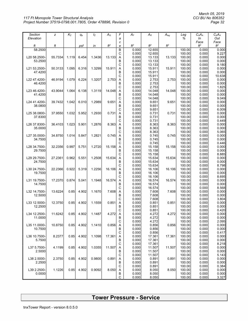
March 05, 2019 117 Ft Monopole Tower Structural Analysis CCI BU No 806352 Project Number 37519-0798.001.7805, Order 478896, Revision 0 Page 32
tnxTower Report - version 8.0.5.0
Section Elevation
ft
z
ft
KZ
qz
psf
tZ
in
AG
ft2
F a c e
AF
ft2
AR
ft2
Aleg
ft2
Leg %
CAAA In
Face ft2
CAAA Out
Face ft2
58.2500 B C
0.000 0.000
12.655 12.655
100.00 100.00
0.000 0.000
0.000 9.227
L20 58.2500-53.2500
55.7334 1.119 6.454 1.3436 13.133 A B C
0.000 0.000 0.000
13.133 13.133 13.133
13.133 100.00 100.00 100.00
0.000 0.000 0.000
0.000 0.000 9.180
L21 53.2500-47.4200
50.3133 1.095 6.316 1.3299 15.911 A B C
0.000 0.000 0.000
15.911 15.911 15.911
15.911 100.00 100.00 100.00
0.000 0.000 0.000
0.000 0.000
10.638 L22 47.4200-
46.4200 46.9194 1.079 6.224 1.3207 2.753 A
B C
0.000 0.000 0.000
2.753 2.753 2.753
2.753 100.00 100.00 100.00
0.000 0.000 0.000
0.000 0.000 1.825
L23 46.4200-41.4200
43.9044 1.064 6.138 1.3119 14.048 A B C
0.000 0.000 0.000
14.048 14.048 14.048
14.048 100.00 100.00 100.00
0.000 0.000 0.000
0.000 0.000 9.049
L24 41.4200-38.0800
39.7432 1.042 6.010 1.2989 9.651 A B C
0.000 0.000 0.000
9.651 9.651 9.651
9.651 100.00 100.00 100.00
0.000 0.000 0.000
0.000 0.000 6.009
L25 38.0800-37.8300
37.9550 1.032 5.952 1.2930 0.731 A B C
0.000 0.000 0.000
0.731 0.731 0.731
0.731 100.00 100.00 100.00
0.000 0.000 0.000
0.000 0.000 0.449
L26 37.8300-35.0000
36.4103 1.023 5.901 1.2876 8.363 A B C
0.000 0.000 0.000
8.363 8.363 8.363
8.363 100.00 100.00 100.00
0.000 0.000 0.000
0.000 0.000 5.065
L27 35.0000-34.7500
34.8750 1.014 5.847 1.2821 0.745 A B C
0.000 0.000 0.000
0.745 0.745 0.745
0.745 100.00 100.00 100.00
0.000 0.000 0.000
0.000 0.000 0.446
L28 34.7500-29.7500
32.2356 0.997 5.751 1.2720 15.158 A B C
0.000 0.000 0.000
15.158 15.158 15.158
15.158 100.00 100.00 100.00
0.000 0.000 0.000
0.000 0.000 8.885
L29 29.7500-24.7500
27.2361 0.962 5.551 1.2508 15.634 A B C
0.000 0.000 0.000
15.634 15.634 15.634
15.634 100.00 100.00 100.00
0.000 0.000 0.000
0.000 0.000 8.798
L30 24.7500-19.7500
22.2366 0.922 5.319 1.2256 16.106 A B C
0.000 0.000 0.000
16.106 16.106 16.106
16.106 100.00 100.00 100.00
0.000 0.000 0.000
0.000 0.000 8.695
L31 19.7500-14.7500
17.2370 0.874 5.041 1.1948 16.574 A B C
0.000 0.000 0.000
16.574 16.574 16.574
16.574 100.00 100.00 100.00
0.000 0.000 0.000
0.000 0.000 8.568
L32 14.7500-12.5000
13.6224 0.85 4.902 1.1670 7.608 A B C
0.000 0.000 0.000
7.608 7.608 7.608
7.608 100.00 100.00 100.00
0.000 0.000 0.000
0.000 0.000 3.804
L33 12.5000-12.2500
12.3750 0.85 4.902 1.1559 0.851 A B C
0.000 0.000 0.000
0.851 0.851 0.851
0.851 100.00 100.00 100.00
0.000 0.000 0.000
0.000 0.000 0.420
L34 12.2500-11.0000
11.6242 0.85 4.902 1.1487 4.272 A B C
0.000 0.000 0.000
4.272 4.272 4.272
4.272 100.00 100.00 100.00
0.000 0.000 0.000
0.000 0.000 2.095
L35 11.0000-10.7500
10.8750 0.85 4.902 1.1410 0.856 A B C
0.000 0.000 0.000
0.856 0.856 0.856
0.856 100.00 100.00 100.00
0.000 0.000 0.000
0.000 0.000 0.417
L36 10.7500-5.7500
8.2377 0.85 4.902 1.1098 17.361 A B C
0.000 0.000 0.000
17.361 17.361 17.361
17.361 100.00 100.00 100.00
0.000 0.000 0.000
0.000 0.000 8.218
L37 5.7500-2.5000
4.1199 0.85 4.902 1.0355 11.507 A B C
0.000 0.000 0.000
11.507 11.507 11.507
11.507 100.00 100.00 100.00
0.000 0.000 0.000
0.000 0.000 5.143
L38 2.5000-2.2500
2.3750 0.85 4.902 0.9800 0.891 A B C
0.000 0.000 0.000
0.891 0.891 0.891
0.891 100.00 100.00 100.00
0.000 0.000 0.000
0.000 0.000 0.384
L39 2.2500-0.0000
1.1226 0.85 4.902 0.9092 8.050 A B C
0.000 0.000 0.000
8.050 8.050 8.050
8.050 100.00 100.00 100.00
0.000 0.000 0.000
0.000 0.000 3.327
Tower Pressure - Service

March 05, 2019 117 Ft Monopole Tower Structural Analysis CCI BU No 806352 Project Number 37519-0798.001.7805, Order 478896, Revision 0 Page 33
tnxTower Report - version 8.0.5.0
GH = 1.100
Section
Elevation
ft
z
ft
KZ
qz
psf
AG
ft2
F a c e
AF
ft2
AR
ft2
Aleg
ft2
Leg %
CAAA In
Face ft2
CAAA Out
Face ft2
L1 117.0000-112.0000
114.4685 1.302 10.185
6.410 A B C
0.000 0.000 0.000
6.410 6.410 6.410
6.410 100.00 100.00 100.00
0.000 0.000 0.000
0.000 0.000 0.000
L2 112.0000-110.0000
110.9952 1.294 10.119
2.700 A B C
0.000 0.000 0.000
2.700 2.700 2.700
2.700 100.00 100.00 100.00
0.000 0.000 0.000
0.000 0.000 0.000
L3 110.0000-105.0000
107.4715 1.285 10.051
7.092 A B C
0.000 0.000 0.000
7.092 7.092 7.092
7.092 100.00 100.00 100.00
0.000 0.000 0.000
0.000 0.000 0.813
L4 105.0000-100.0000
102.4733 1.272 9.950 7.580 A B C
0.000 0.000 0.000
7.580 7.580 7.580
7.580 100.00 100.00 100.00
0.000 0.000 0.000
0.000 0.000 0.813
L5 100.0000-95.0000
97.4751 1.259 9.846 8.056 A B C
0.000 0.000 0.000
8.056 8.056 8.056
8.056 100.00 100.00 100.00
0.000 0.000 0.000
0.000 0.000 0.813
L6 95.0000-90.0000
92.4765 1.245 9.738 8.540 A B C
0.000 0.000 0.000
8.540 8.540 8.540
8.540 100.00 100.00 100.00
0.000 0.000 0.000
0.000 0.000 0.987
L7 90.0000-85.0000
87.4777 1.23 9.624 9.024 A B C
0.000 0.000 0.000
9.024 9.024 9.024
9.024 100.00 100.00 100.00
0.000 0.000 0.000
0.000 0.000 1.103
L8 85.0000-81.8800
83.4317 1.218 9.529 5.876 A B C
0.000 0.000 0.000
5.876 5.876 5.876
5.876 100.00 100.00 100.00
0.000 0.000 0.000
0.000 0.000 1.417
L9 81.8800-81.6300
81.7549 1.213 9.488 0.478 A B C
0.000 0.000 0.000
0.478 0.478 0.478
0.478 100.00 100.00 100.00
0.000 0.000 0.000
0.000 0.000 0.141
L10 81.6300-76.6300
79.1096 1.205 9.423 9.819 A B C
0.000 0.000 0.000
9.819 9.819 9.819
9.819 100.00 100.00 100.00
0.000 0.000 0.000
0.000 0.000 2.879
L11 76.6300-76.0800
76.3548 1.196 9.353 1.110 A B C
0.000 0.000 0.000
1.110 1.110 1.110
1.110 100.00 100.00 100.00
0.000 0.000 0.000
0.000 0.000 0.379
L12 76.0800-75.8300
75.9550 1.194 9.342 0.506 A B C
0.000 0.000 0.000
0.506 0.506 0.506
0.506 100.00 100.00 100.00
0.000 0.000 0.000
0.000 0.000 0.172
L13 75.8300-71.0000
73.3969 1.186 9.275 10.005 A B C
0.000 0.000 0.000
10.005 10.005 10.005
10.005 100.00 100.00 100.00
0.000 0.000 0.000
0.000 0.000 3.393
L14 71.0000-70.7500
70.8750 1.177 9.207 0.529 A B C
0.000 0.000 0.000
0.529 0.529 0.529
0.529 100.00 100.00 100.00
0.000 0.000 0.000
0.000 0.000 0.183
L15 70.7500-68.0800
69.4097 1.172 9.167 5.721 A B C
0.000 0.000 0.000
5.721 5.721 5.721
5.721 100.00 100.00 100.00
0.000 0.000 0.000
0.000 0.000 1.952
L16 68.0800-67.8300
67.9550 1.167 9.126 0.542 A B C
0.000 0.000 0.000
0.542 0.542 0.542
0.542 100.00 100.00 100.00
0.000 0.000 0.000
0.000 0.000 0.183
L17 67.8300-63.5000
65.6515 1.158 9.060 9.590 A B C
0.000 0.000 0.000
9.590 9.590 9.590
9.590 100.00 100.00 100.00
0.000 0.000 0.000
0.000 0.000 3.166
L18 63.5000-63.2500
63.3750 1.15 8.993 0.563 A B C
0.000 0.000 0.000
0.563 0.563 0.563
0.563 100.00 100.00 100.00
0.000 0.000 0.000
0.000 0.000 0.183
L19 63.2500-58.2500
60.7327 1.139 8.913 11.526 A B C
0.000 0.000 0.000
11.526 11.526 11.526
11.526 100.00 100.00 100.00
0.000 0.000 0.000
0.000 0.000 3.656
L20 58.2500-53.2500
55.7334 1.119 8.753 12.013 A B C
0.000 0.000 0.000
12.013 12.013 12.013
12.013 100.00 100.00 100.00
0.000 0.000 0.000
0.000 0.000 3.656
L21 53.2500-47.4200
50.3133 1.095 8.566 14.619 A B C
0.000 0.000 0.000
14.619 14.619 14.619
14.619 100.00 100.00 100.00
0.000 0.000 0.000
0.000 0.000 4.263
L22 47.4200-46.4200
46.9194 1.079 8.441 2.531 A B
0.000 0.000
2.531 2.531
2.531 100.00 100.00
0.000 0.000
0.000 0.000
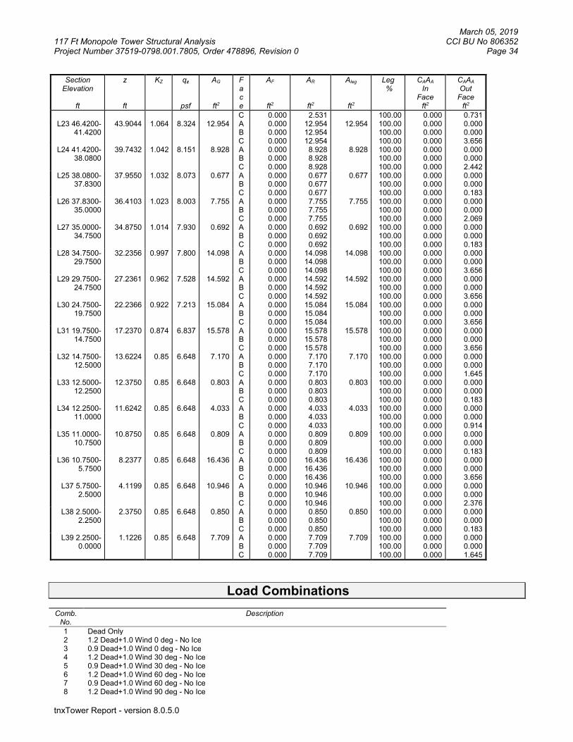
March 05, 2019 117 Ft Monopole Tower Structural Analysis CCI BU No 806352 Project Number 37519-0798.001.7805, Order 478896, Revision 0 Page 34
tnxTower Report - version 8.0.5.0
Section Elevation
ft
z
ft
KZ
qz
psf
AG
ft2
F a c e
AF
ft2
AR
ft2
Aleg
ft2
Leg %
CAAA In
Face ft2
CAAA Out
Face ft2
C 0.000 2.531 100.00 0.000 0.731 L23 46.4200-
41.4200 43.9044 1.064 8.324 12.954 A
B C
0.000 0.000 0.000
12.954 12.954 12.954
12.954 100.00 100.00 100.00
0.000 0.000 0.000
0.000 0.000 3.656
L24 41.4200-38.0800
39.7432 1.042 8.151 8.928 A B C
0.000 0.000 0.000
8.928 8.928 8.928
8.928 100.00 100.00 100.00
0.000 0.000 0.000
0.000 0.000 2.442
L25 38.0800-37.8300
37.9550 1.032 8.073 0.677 A B C
0.000 0.000 0.000
0.677 0.677 0.677
0.677 100.00 100.00 100.00
0.000 0.000 0.000
0.000 0.000 0.183
L26 37.8300-35.0000
36.4103 1.023 8.003 7.755 A B C
0.000 0.000 0.000
7.755 7.755 7.755
7.755 100.00 100.00 100.00
0.000 0.000 0.000
0.000 0.000 2.069
L27 35.0000-34.7500
34.8750 1.014 7.930 0.692 A B C
0.000 0.000 0.000
0.692 0.692 0.692
0.692 100.00 100.00 100.00
0.000 0.000 0.000
0.000 0.000 0.183
L28 34.7500-29.7500
32.2356 0.997 7.800 14.098 A B C
0.000 0.000 0.000
14.098 14.098 14.098
14.098 100.00 100.00 100.00
0.000 0.000 0.000
0.000 0.000 3.656
L29 29.7500-24.7500
27.2361 0.962 7.528 14.592 A B C
0.000 0.000 0.000
14.592 14.592 14.592
14.592 100.00 100.00 100.00
0.000 0.000 0.000
0.000 0.000 3.656
L30 24.7500-19.7500
22.2366 0.922 7.213 15.084 A B C
0.000 0.000 0.000
15.084 15.084 15.084
15.084 100.00 100.00 100.00
0.000 0.000 0.000
0.000 0.000 3.656
L31 19.7500-14.7500
17.2370 0.874 6.837 15.578 A B C
0.000 0.000 0.000
15.578 15.578 15.578
15.578 100.00 100.00 100.00
0.000 0.000 0.000
0.000 0.000 3.656
L32 14.7500-12.5000
13.6224 0.85 6.648 7.170 A B C
0.000 0.000 0.000
7.170 7.170 7.170
7.170 100.00 100.00 100.00
0.000 0.000 0.000
0.000 0.000 1.645
L33 12.5000-12.2500
12.3750 0.85 6.648 0.803 A B C
0.000 0.000 0.000
0.803 0.803 0.803
0.803 100.00 100.00 100.00
0.000 0.000 0.000
0.000 0.000 0.183
L34 12.2500-11.0000
11.6242 0.85 6.648 4.033 A B C
0.000 0.000 0.000
4.033 4.033 4.033
4.033 100.00 100.00 100.00
0.000 0.000 0.000
0.000 0.000 0.914
L35 11.0000-10.7500
10.8750 0.85 6.648 0.809 A B C
0.000 0.000 0.000
0.809 0.809 0.809
0.809 100.00 100.00 100.00
0.000 0.000 0.000
0.000 0.000 0.183
L36 10.7500-5.7500
8.2377 0.85 6.648 16.436 A B C
0.000 0.000 0.000
16.436 16.436 16.436
16.436 100.00 100.00 100.00
0.000 0.000 0.000
0.000 0.000 3.656
L37 5.7500-2.5000
4.1199 0.85 6.648 10.946 A B C
0.000 0.000 0.000
10.946 10.946 10.946
10.946 100.00 100.00 100.00
0.000 0.000 0.000
0.000 0.000 2.376
L38 2.5000-2.2500
2.3750 0.85 6.648 0.850 A B C
0.000 0.000 0.000
0.850 0.850 0.850
0.850 100.00 100.00 100.00
0.000 0.000 0.000
0.000 0.000 0.183
L39 2.2500-0.0000
1.1226 0.85 6.648 7.709 A B C
0.000 0.000 0.000
7.709 7.709 7.709
7.709 100.00 100.00 100.00
0.000 0.000 0.000
0.000 0.000 1.645
Load Combinations Comb.
No. Description
1 Dead Only 2 1.2 Dead+1.0 Wind 0 deg - No Ice 3 0.9 Dead+1.0 Wind 0 deg - No Ice 4 1.2 Dead+1.0 Wind 30 deg - No Ice 5 0.9 Dead+1.0 Wind 30 deg - No Ice 6 1.2 Dead+1.0 Wind 60 deg - No Ice 7 0.9 Dead+1.0 Wind 60 deg - No Ice 8 1.2 Dead+1.0 Wind 90 deg - No Ice

March 05, 2019 117 Ft Monopole Tower Structural Analysis CCI BU No 806352 Project Number 37519-0798.001.7805, Order 478896, Revision 0 Page 35
tnxTower Report - version 8.0.5.0
Comb. No.
Description
9 0.9 Dead+1.0 Wind 90 deg - No Ice 10 1.2 Dead+1.0 Wind 120 deg - No Ice 11 0.9 Dead+1.0 Wind 120 deg - No Ice 12 1.2 Dead+1.0 Wind 150 deg - No Ice 13 0.9 Dead+1.0 Wind 150 deg - No Ice 14 1.2 Dead+1.0 Wind 180 deg - No Ice 15 0.9 Dead+1.0 Wind 180 deg - No Ice 16 1.2 Dead+1.0 Wind 210 deg - No Ice 17 0.9 Dead+1.0 Wind 210 deg - No Ice 18 1.2 Dead+1.0 Wind 240 deg - No Ice 19 0.9 Dead+1.0 Wind 240 deg - No Ice 20 1.2 Dead+1.0 Wind 270 deg - No Ice 21 0.9 Dead+1.0 Wind 270 deg - No Ice 22 1.2 Dead+1.0 Wind 300 deg - No Ice 23 0.9 Dead+1.0 Wind 300 deg - No Ice 24 1.2 Dead+1.0 Wind 330 deg - No Ice 25 0.9 Dead+1.0 Wind 330 deg - No Ice 26 1.2 Dead+1.0 Ice+1.0 Temp 27 1.2 Dead+1.0 Wind 0 deg+1.0 Ice+1.0 Temp 28 1.2 Dead+1.0 Wind 30 deg+1.0 Ice+1.0 Temp 29 1.2 Dead+1.0 Wind 60 deg+1.0 Ice+1.0 Temp 30 1.2 Dead+1.0 Wind 90 deg+1.0 Ice+1.0 Temp 31 1.2 Dead+1.0 Wind 120 deg+1.0 Ice+1.0 Temp 32 1.2 Dead+1.0 Wind 150 deg+1.0 Ice+1.0 Temp 33 1.2 Dead+1.0 Wind 180 deg+1.0 Ice+1.0 Temp 34 1.2 Dead+1.0 Wind 210 deg+1.0 Ice+1.0 Temp 35 1.2 Dead+1.0 Wind 240 deg+1.0 Ice+1.0 Temp 36 1.2 Dead+1.0 Wind 270 deg+1.0 Ice+1.0 Temp 37 1.2 Dead+1.0 Wind 300 deg+1.0 Ice+1.0 Temp 38 1.2 Dead+1.0 Wind 330 deg+1.0 Ice+1.0 Temp 39 Dead+Wind 0 deg - Service 40 Dead+Wind 30 deg - Service 41 Dead+Wind 60 deg - Service 42 Dead+Wind 90 deg - Service 43 Dead+Wind 120 deg - Service 44 Dead+Wind 150 deg - Service 45 Dead+Wind 180 deg - Service 46 Dead+Wind 210 deg - Service 47 Dead+Wind 240 deg - Service 48 Dead+Wind 270 deg - Service 49 Dead+Wind 300 deg - Service 50 Dead+Wind 330 deg - Service
Maximum Member Forces Sectio
n No.
Elevation ft
Component Type
Condition Gov. Load
Comb.
Axial
K
Major Axis Moment
kip-ft
Minor Axis Moment
kip-ft
L1 117 - 112 Pole Max Tension 26 0.00 -0.00 0.00 Max. Compression 26 -4.62 -0.70 -0.40 Max. Mx 8 -1.64 -21.80 -0.53 Max. My 14 -1.62 -0.65 -22.92 Max. Vy 8 3.83 -21.80 -0.53 Max. Vx 14 4.01 -0.65 -22.92 Max. Torque 16 0.40
L2 112 - 110 Pole Max Tension 1 0.00 0.00 0.00 Max. Compression 26 -4.76 -0.70 -0.40 Max. Mx 8 -1.71 -29.58 -0.64 Max. My 14 -1.69 -0.75 -31.07 Max. Vy 8 3.96 -29.58 -0.64 Max. Vx 14 4.14 -0.75 -31.07 Max. Torque 16 0.40
L3 110 - 105 Pole Max Tension 1 0.00 0.00 0.00 Max. Compression 26 -9.79 -0.75 -0.41 Max. Mx 8 -3.97 -67.79 -0.93 Max. My 14 -3.94 -1.05 -70.17 Max. Vy 8 7.11 -67.79 -0.93

March 05, 2019 117 Ft Monopole Tower Structural Analysis CCI BU No 806352 Project Number 37519-0798.001.7805, Order 478896, Revision 0 Page 36
tnxTower Report - version 8.0.5.0
Section
No.
Elevation ft
Component Type
Condition Gov. Load
Comb.
Axial
K
Major Axis Moment
kip-ft
Minor Axis Moment
kip-ft
Max. Vx 2 -7.30 0.42 69.78 Max. Torque 16 0.41
L4 105 - 100 Pole Max Tension 1 0.00 0.00 0.00 Max. Compression 26 -10.28 -0.72 -0.43 Max. Mx 8 -4.26 -104.27 -1.20 Max. My 14 -4.24 -1.30 -107.58 Max. Vy 20 -7.49 103.55 0.85 Max. Vx 2 -7.67 0.70 107.18 Max. Torque 16 0.40
L5 100 - 95 Pole Max Tension 1 0.00 0.00 0.00 Max. Compression 26 -19.83 -0.07 -0.17 Max. Mx 8 -7.94 -179.31 -1.28 Max. My 14 -7.91 -1.28 -183.75 Max. Vy 20 -14.40 178.90 1.07 Max. Vx 2 -14.61 0.97 183.52 Max. Torque 16 0.39
L6 95 - 90 Pole Max Tension 1 0.00 0.00 0.00 Max. Compression 26 -21.18 0.32 0.09 Max. Mx 8 -8.70 -255.20 -0.39 Max. My 2 -8.68 -0.42 260.19 Max. Vy 20 -15.62 254.94 0.29 Max. Vx 14 15.71 -0.03 -260.16 Max. Torque 15 -1.59
L7 90 - 85 Pole Max Tension 1 0.00 0.00 0.00 Max. Compression 26 -31.34 1.00 0.78 Max. Mx 8 -13.31 -359.63 1.46 Max. My 2 -13.30 -2.80 364.97 Max. Vy 20 -22.35 359.33 -0.86 Max. Vx 14 22.33 1.98 -364.21 Max. Torque 15 -2.85
L8 85 - 81.88 Pole Max Tension 1 0.00 0.00 0.00 Max. Compression 26 -32.77 1.13 0.71 Max. Mx 8 -14.10 -430.92 2.43 Max. My 2 -14.09 -4.25 436.21 Max. Vy 20 -23.19 430.68 -1.89 Max. Vx 14 23.17 3.39 -435.48 Max. Torque 15 -2.89
L9 81.88 - 81.63
Pole Max Tension 1 0.00 0.00 0.00
Max. Compression 26 -32.84 1.15 0.70 Max. Mx 8 -14.17 -436.72 2.50 Max. My 2 -14.16 -4.36 442.00 Max. Vy 20 -23.21 436.48 -1.98 Max. Vx 14 23.18 3.51 -441.27 Max. Torque 15 -2.90
L10 81.63 - 76.63
Pole Max Tension 1 0.00 0.00 0.00
Max. Compression 26 -34.18 1.43 0.55 Max. Mx 8 -15.14 -553.85 4.04 Max. My 2 -15.13 -6.68 559.05 Max. Vy 20 -23.70 553.73 -3.63 Max. Vx 14 23.67 5.77 -558.38 Max. Torque 15 -3.00
L11 76.63 - 76.08
Pole Max Tension 1 0.00 0.00 0.00
Max. Compression 26 -34.33 1.46 0.53 Max. Mx 8 -15.26 -566.88 4.21 Max. My 2 -15.25 -6.93 572.08 Max. Vy 20 -23.75 566.77 -3.82 Max. Vx 14 23.72 6.02 -571.41 Max. Torque 15 -3.02
L12 76.08 - 75.83
Pole Max Tension 1 0.00 0.00 0.00
Max. Compression 26 -34.41 1.48 0.52 Max. Mx 8 -15.32 -572.82 4.29 Max. My 2 -15.32 -7.05 578.01 Max. Vy 20 -23.77 572.71 -3.90 Max. Vx 14 23.74 6.13 -577.34 Max. Torque 15 -3.02

March 05, 2019 117 Ft Monopole Tower Structural Analysis CCI BU No 806352 Project Number 37519-0798.001.7805, Order 478896, Revision 0 Page 37
tnxTower Report - version 8.0.5.0
Section
No.
Elevation ft
Component Type
Condition Gov. Load
Comb.
Axial
K
Major Axis Moment
kip-ft
Minor Axis Moment
kip-ft
L13 75.83 - 71 Pole Max Tension 1 0.00 0.00 0.00 Max. Compression 26 -35.90 1.76 0.37 Max. Mx 20 -16.43 688.78 -5.50 Max. My 2 -16.43 -9.28 693.88 Max. Vy 20 -24.30 688.78 -5.50 Max. Vx 14 24.27 8.31 -693.27 Max. Torque 15 -3.15
L14 71 - 70.75 Pole Max Tension 1 0.00 0.00 0.00 Max. Compression 26 -36.00 1.78 0.36 Max. Mx 20 -16.52 694.86 -5.58 Max. My 2 -16.52 -9.40 699.95 Max. Vy 20 -24.32 694.86 -5.58 Max. Vx 14 24.29 8.42 -699.34 Max. Torque 15 -3.15
L15 70.75 - 68.08
Pole Max Tension 1 0.00 0.00 0.00
Max. Compression 26 -36.98 1.93 0.27 Max. Mx 20 -17.26 760.20 -6.47 Max. My 2 -17.26 -10.64 765.19 Max. Vy 20 -24.64 760.20 -6.47 Max. Vx 14 24.61 9.63 -764.61 Max. Torque 15 -3.23
L16 68.08 - 67.83
Pole Max Tension 1 0.00 0.00 0.00
Max. Compression 26 -37.07 1.95 0.26 Max. Mx 20 -17.34 766.37 -6.55 Max. My 2 -17.34 -10.75 771.34 Max. Vy 20 -24.66 766.37 -6.55 Max. Vx 14 24.63 9.74 -770.77 Max. Torque 15 -3.24
L17 67.83 - 63.5 Pole Max Tension 1 0.00 0.00 0.00 Max. Compression 26 -38.60 2.21 0.11 Max. Mx 20 -18.50 874.22 -7.99 Max. My 2 -18.50 -12.75 879.01 Max. Vy 20 -25.16 874.22 -7.99 Max. Vx 14 25.14 11.69 -878.50 Max. Torque 15 -3.36
L18 63.5 - 63.25 Pole Max Tension 1 0.00 0.00 0.00 Max. Compression 26 -38.70 2.24 0.10 Max. Mx 20 -18.59 880.52 -8.07 Max. My 2 -18.59 -12.87 885.30 Max. Vy 20 -25.19 880.52 -8.07 Max. Vx 14 25.16 11.81 -884.78 Max. Torque 15 -3.37
L19 63.25 - 58.25
Pole Max Tension 1 0.00 0.00 0.00
Max. Compression 26 -40.76 2.54 -0.07 Max. Mx 20 -20.20 1007.97 -9.73 Max. My 2 -20.19 -15.18 1012.54 Max. Vy 20 -25.79 1007.97 -9.73 Max. Vx 14 25.77 14.06 -1012.09 Max. Torque 15 -3.51
L20 58.25 - 53.25
Pole Max Tension 1 0.00 0.00 0.00
Max. Compression 26 -42.84 2.84 -0.25 Max. Mx 20 -21.84 1138.41 -11.39 Max. My 2 -21.84 -17.49 1142.77 Max. Vy 20 -26.39 1138.41 -11.39 Max. Vx 14 26.36 16.32 -1142.39 Max. Torque 15 -3.67
L21 53.25 - 47.42
Pole Max Tension 1 0.00 0.00 0.00
Max. Compression 26 -43.37 2.91 -0.29 Max. Mx 20 -22.25 1171.49 -11.80 Max. My 2 -22.25 -18.07 1175.80 Max. Vy 20 -26.54 1171.49 -11.80 Max. Vx 14 26.51 16.88 -1175.43 Max. Torque 15 -3.70
L22 47.42 - Pole Max Tension 1 0.00 0.00 0.00

March 05, 2019 117 Ft Monopole Tower Structural Analysis CCI BU No 806352 Project Number 37519-0798.001.7805, Order 478896, Revision 0 Page 38
tnxTower Report - version 8.0.5.0
Section
No.
Elevation ft
Component Type
Condition Gov. Load
Comb.
Axial
K
Major Axis Moment
kip-ft
Minor Axis Moment
kip-ft
46.42 Max. Compression 26 -47.34 3.26 -0.50 Max. Mx 20 -25.45 1321.69 -13.66 Max. My 2 -25.45 -20.65 1325.75 Max. Vy 20 -27.28 1321.69 -13.66 Max. Vx 14 27.26 19.40 -1325.45 Max. Torque 15 -3.88
L23 46.42 - 41.42
Pole Max Tension 1 0.00 0.00 0.00
Max. Compression 26 -49.56 3.57 -0.68 Max. Mx 20 -27.24 1459.51 -15.32 Max. My 2 -27.24 -22.96 1463.35 Max. Vy 20 -27.85 1459.51 -15.32 Max. Vx 14 27.83 21.66 -1463.12 Max. Torque 15 -4.03
L24 41.42 - 38.08
Pole Max Tension 1 0.00 0.00 0.00
Max. Compression 26 -51.06 3.79 -0.81 Max. Mx 20 -28.45 1553.15 -16.43 Max. My 2 -28.45 -24.50 1556.85 Max. Vy 20 -28.23 1553.15 -16.43 Max. Vx 14 28.20 23.16 -1556.66 Max. Torque 15 -4.13
L25 38.08 - 37.83
Pole Max Tension 1 0.00 0.00 0.00
Max. Compression 26 -51.16 3.81 -0.82 Max. Mx 20 -28.55 1560.21 -16.52 Max. My 2 -28.55 -24.61 1563.89 Max. Vy 20 -28.25 1560.21 -16.52 Max. Vx 14 28.22 23.27 -1563.72 Max. Torque 15 -4.14
L26 37.83 - 35 Pole Max Tension 1 0.00 0.00 0.00 Max. Compression 26 -52.39 3.98 -0.92 Max. Mx 20 -29.53 1640.60 -17.45 Max. My 2 -29.53 -25.91 1644.15 Max. Vy 20 -28.57 1640.60 -17.45 Max. Vx 14 28.54 24.55 -1644.01 Max. Torque 15 -4.23
L27 35 - 34.75 Pole Max Tension 1 0.00 0.00 0.00 Max. Compression 26 -52.51 4.01 -0.93 Max. Mx 20 -29.64 1647.74 -17.54 Max. My 2 -29.64 -26.03 1651.29 Max. Vy 20 -28.58 1647.74 -17.54 Max. Vx 14 28.55 24.66 -1651.15 Max. Torque 15 -4.24
L28 34.75 - 29.75
Pole Max Tension 1 0.00 0.00 0.00
Max. Compression 26 -54.88 4.33 -1.13 Max. Mx 20 -31.57 1792.04 -19.19 Max. My 2 -31.57 -28.32 1795.35 Max. Vy 20 -29.14 1792.04 -19.19 Max. Vx 14 29.11 26.90 -1795.29 Max. Torque 15 -4.40
L29 29.75 - 24.75
Pole Max Tension 1 0.00 0.00 0.00
Max. Compression 26 -57.27 4.66 -1.32 Max. Mx 20 -33.55 1939.02 -20.85 Max. My 14 -33.55 29.14 -1942.12 Max. Vy 20 -29.67 1939.02 -20.85 Max. Vx 14 29.64 29.14 -1942.12 Max. Torque 15 -4.55
L30 24.75 - 19.75
Pole Max Tension 1 0.00 0.00 0.00
Max. Compression 26 -59.68 4.99 -1.51 Max. Mx 20 -35.55 2088.59 -22.49 Max. My 14 -35.55 31.37 -2091.53 Max. Vy 20 -30.17 2088.59 -22.49 Max. Vx 14 30.14 31.37 -2091.53 Max. Torque 15 -4.71
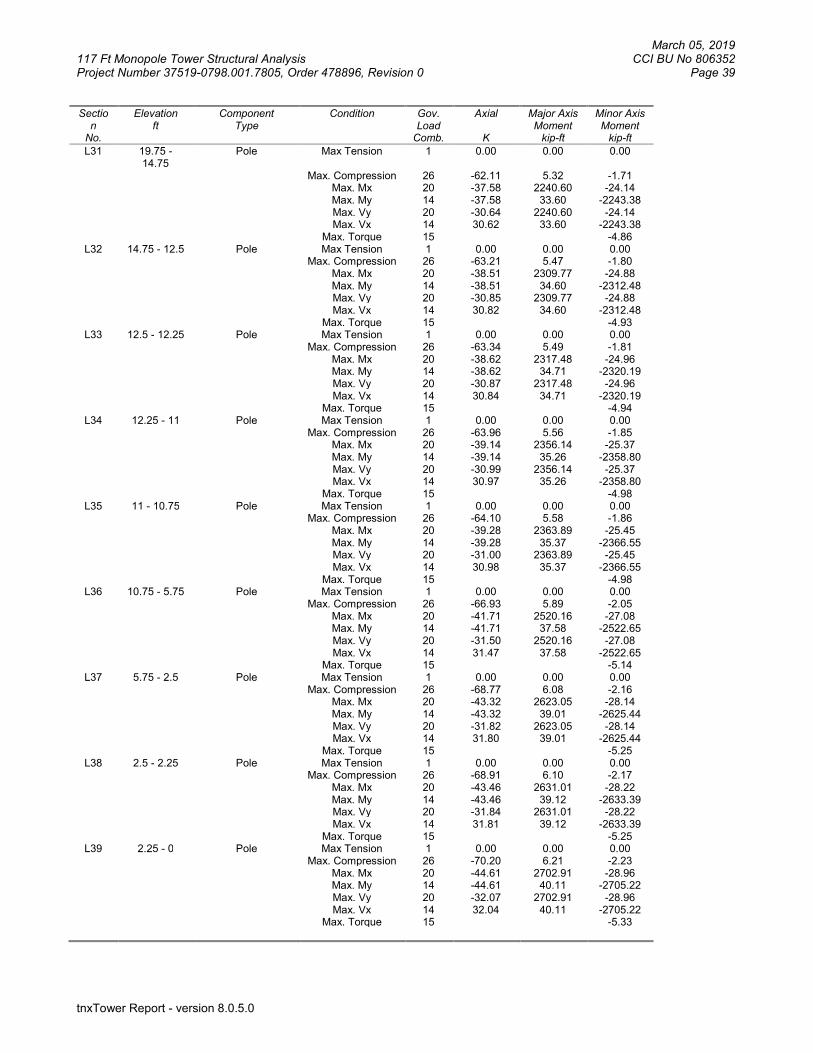
March 05, 2019 117 Ft Monopole Tower Structural Analysis CCI BU No 806352 Project Number 37519-0798.001.7805, Order 478896, Revision 0 Page 39
tnxTower Report - version 8.0.5.0
Section
No.
Elevation ft
Component Type
Condition Gov. Load
Comb.
Axial
K
Major Axis Moment
kip-ft
Minor Axis Moment
kip-ft
L31 19.75 - 14.75
Pole Max Tension 1 0.00 0.00 0.00
Max. Compression 26 -62.11 5.32 -1.71 Max. Mx 20 -37.58 2240.60 -24.14 Max. My 14 -37.58 33.60 -2243.38 Max. Vy 20 -30.64 2240.60 -24.14 Max. Vx 14 30.62 33.60 -2243.38 Max. Torque 15 -4.86
L32 14.75 - 12.5 Pole Max Tension 1 0.00 0.00 0.00 Max. Compression 26 -63.21 5.47 -1.80 Max. Mx 20 -38.51 2309.77 -24.88 Max. My 14 -38.51 34.60 -2312.48 Max. Vy 20 -30.85 2309.77 -24.88 Max. Vx 14 30.82 34.60 -2312.48 Max. Torque 15 -4.93
L33 12.5 - 12.25 Pole Max Tension 1 0.00 0.00 0.00 Max. Compression 26 -63.34 5.49 -1.81 Max. Mx 20 -38.62 2317.48 -24.96 Max. My 14 -38.62 34.71 -2320.19 Max. Vy 20 -30.87 2317.48 -24.96 Max. Vx 14 30.84 34.71 -2320.19 Max. Torque 15 -4.94
L34 12.25 - 11 Pole Max Tension 1 0.00 0.00 0.00 Max. Compression 26 -63.96 5.56 -1.85 Max. Mx 20 -39.14 2356.14 -25.37 Max. My 14 -39.14 35.26 -2358.80 Max. Vy 20 -30.99 2356.14 -25.37 Max. Vx 14 30.97 35.26 -2358.80 Max. Torque 15 -4.98
L35 11 - 10.75 Pole Max Tension 1 0.00 0.00 0.00 Max. Compression 26 -64.10 5.58 -1.86 Max. Mx 20 -39.28 2363.89 -25.45 Max. My 14 -39.28 35.37 -2366.55 Max. Vy 20 -31.00 2363.89 -25.45 Max. Vx 14 30.98 35.37 -2366.55 Max. Torque 15 -4.98
L36 10.75 - 5.75 Pole Max Tension 1 0.00 0.00 0.00 Max. Compression 26 -66.93 5.89 -2.05 Max. Mx 20 -41.71 2520.16 -27.08 Max. My 14 -41.71 37.58 -2522.65 Max. Vy 20 -31.50 2520.16 -27.08 Max. Vx 14 31.47 37.58 -2522.65 Max. Torque 15 -5.14
L37 5.75 - 2.5 Pole Max Tension 1 0.00 0.00 0.00 Max. Compression 26 -68.77 6.08 -2.16 Max. Mx 20 -43.32 2623.05 -28.14 Max. My 14 -43.32 39.01 -2625.44 Max. Vy 20 -31.82 2623.05 -28.14 Max. Vx 14 31.80 39.01 -2625.44 Max. Torque 15 -5.25
L38 2.5 - 2.25 Pole Max Tension 1 0.00 0.00 0.00 Max. Compression 26 -68.91 6.10 -2.17 Max. Mx 20 -43.46 2631.01 -28.22 Max. My 14 -43.46 39.12 -2633.39 Max. Vy 20 -31.84 2631.01 -28.22 Max. Vx 14 31.81 39.12 -2633.39 Max. Torque 15 -5.25
L39 2.25 - 0 Pole Max Tension 1 0.00 0.00 0.00 Max. Compression 26 -70.20 6.21 -2.23 Max. Mx 20 -44.61 2702.91 -28.96 Max. My 14 -44.61 40.11 -2705.22 Max. Vy 20 -32.07 2702.91 -28.96 Max. Vx 14 32.04 40.11 -2705.22 Max. Torque 15 -5.33

March 05, 2019 117 Ft Monopole Tower Structural Analysis CCI BU No 806352 Project Number 37519-0798.001.7805, Order 478896, Revision 0 Page 40
tnxTower Report - version 8.0.5.0
Maximum Reactions
Location Condition Gov. Load
Comb.
Vertical K
Horizontal, X K
Horizontal, Z K
Pole Max. Vert 26 70.20 -0.00 0.00 Max. Hx 21 33.46 32.06 -0.32 Max. Hz 2 44.62 -0.46 32.03 Max. Mx 2 2704.82 -0.46 32.03 Max. Mz 8 2700.99 -32.05 0.30 Max. Torsion 25 4.37 15.77 27.51 Min. Vert 9 33.46 -32.05 0.30 Min. Hx 9 33.46 -32.05 0.30 Min. Hz 15 33.46 0.43 -32.03 Min. Mx 14 -2705.22 0.43 -32.03 Min. Mz 20 -2702.91 32.06 -0.32 Min. Torsion 15 -5.33 0.43 -32.03
Tower Mast Reaction Summary
Load Combination
Vertical
K
Shearx
K
Shearz
K
Overturning Moment, Mx
kip-ft
Overturning Moment, Mz
kip-ft
Torque
kip-ft Dead Only 37.18 0.00 -0.00 -0.02 0.37 0.00 1.2 Dead+1.0 Wind 0 deg - No Ice
44.62 0.46 -32.03 -2704.82 -41.80 -4.10
0.9 Dead+1.0 Wind 0 deg - No Ice
33.46 0.46 -32.03 -2684.70 -41.62 -4.11
1.2 Dead+1.0 Wind 30 deg - No Ice
44.62 16.28 -27.78 -2345.80 -1373.17 -2.80
0.9 Dead+1.0 Wind 30 deg - No Ice
33.46 16.28 -27.78 -2328.37 -1363.12 -2.80
1.2 Dead+1.0 Wind 60 deg - No Ice
44.62 27.87 -16.19 -1368.16 -2349.35 -1.15
0.9 Dead+1.0 Wind 60 deg - No Ice
33.46 27.87 -16.19 -1358.00 -2332.06 -1.14
1.2 Dead+1.0 Wind 90 deg - No Ice
44.62 32.05 -0.30 -27.31 -2700.99 1.00
0.9 Dead+1.0 Wind 90 deg - No Ice
33.46 32.05 -0.30 -27.11 -2681.11 1.01
1.2 Dead+1.0 Wind 120 deg - No Ice
44.62 27.81 15.59 1313.04 -2345.27 3.08
0.9 Dead+1.0 Wind 120 deg - No Ice
33.46 27.81 15.59 1303.28 -2327.98 3.09
1.2 Dead+1.0 Wind 150 deg - No Ice
44.62 15.70 27.57 2327.33 -1320.21 4.64
0.9 Dead+1.0 Wind 150 deg - No Ice
33.46 15.70 27.57 2310.04 -1310.51 4.64
1.2 Dead+1.0 Wind 180 deg - No Ice
44.62 -0.43 32.03 2705.22 40.11 5.32
0.9 Dead+1.0 Wind 180 deg - No Ice
33.46 -0.43 32.03 2685.13 39.73 5.33
1.2 Dead+1.0 Wind 210 deg - No Ice
44.62 -16.28 27.79 2347.16 1374.11 3.92
0.9 Dead+1.0 Wind 210 deg - No Ice
33.46 -16.28 27.79 2329.74 1363.84 3.92
1.2 Dead+1.0 Wind 240 deg - No Ice
44.62 -27.87 16.21 1370.02 2350.54 1.39
0.9 Dead+1.0 Wind 240 deg - No Ice
33.46 -27.87 16.21 1359.87 2333.03 1.39
1.2 Dead+1.0 Wind 270 deg - No Ice
44.62 -32.06 0.32 28.96 2702.91 -1.13
0.9 Dead+1.0 Wind 270 deg - No Ice
33.46 -32.06 0.32 28.77 2682.78 -1.14
1.2 Dead+1.0 Wind 300 deg - No Ice
44.62 -27.78 -15.62 -1316.27 2343.42 -2.82
0.9 Dead+1.0 Wind 300 deg 33.46 -27.78 -15.62 -1306.46 2325.94 -2.83

March 05, 2019 117 Ft Monopole Tower Structural Analysis CCI BU No 806352 Project Number 37519-0798.001.7805, Order 478896, Revision 0 Page 41
tnxTower Report - version 8.0.5.0
Load Combination
Vertical
K
Shearx
K
Shearz
K
Overturning Moment, Mx
kip-ft
Overturning Moment, Mz
kip-ft
Torque
kip-ft - No Ice 1.2 Dead+1.0 Wind 330 deg - No Ice
44.62 -15.77 -27.51 -2321.74 1328.43 -4.36
0.9 Dead+1.0 Wind 330 deg - No Ice
33.46 -15.77 -27.51 -2304.46 1318.46 -4.37
1.2 Dead+1.0 Ice+1.0 Temp 70.20 0.00 -0.00 2.23 6.21 0.00 1.2 Dead+1.0 Wind 0 deg+1.0 Ice+1.0 Temp
70.20 0.08 -8.49 -727.08 -1.20 -1.37
1.2 Dead+1.0 Wind 30 deg+1.0 Ice+1.0 Temp
70.20 4.28 -7.36 -629.52 -361.02 -0.92
1.2 Dead+1.0 Wind 60 deg+1.0 Ice+1.0 Temp
70.20 7.36 -4.27 -364.69 -625.23 -0.31
1.2 Dead+1.0 Wind 90 deg+1.0 Ice+1.0 Temp
70.20 8.48 -0.05 -2.17 -721.15 0.43
1.2 Dead+1.0 Wind 120 deg+1.0 Ice+1.0 Temp
70.20 7.36 4.17 359.78 -625.51 1.09
1.2 Dead+1.0 Wind 150 deg+1.0 Ice+1.0 Temp
70.20 4.19 7.33 631.35 -352.02 1.53
1.2 Dead+1.0 Wind 180 deg+1.0 Ice+1.0 Temp
70.20 -0.08 8.49 731.97 14.17 1.65
1.2 Dead+1.0 Wind 210 deg+1.0 Ice+1.0 Temp
70.20 -4.29 7.36 634.40 374.55 1.17
1.2 Dead+1.0 Wind 240 deg+1.0 Ice+1.0 Temp
70.20 -7.37 4.28 369.78 638.56 0.37
1.2 Dead+1.0 Wind 270 deg+1.0 Ice+1.0 Temp
70.20 -8.49 0.06 7.49 734.62 -0.45
1.2 Dead+1.0 Wind 300 deg+1.0 Ice+1.0 Temp
70.20 -7.36 -4.17 -355.48 638.41 -1.03
1.2 Dead+1.0 Wind 330 deg+1.0 Ice+1.0 Temp
70.20 -4.20 -7.31 -625.50 366.69 -1.47
Dead+Wind 0 deg - Service 37.18 0.11 -7.54 -634.30 -9.53 -0.97 Dead+Wind 30 deg - Service 37.18 3.83 -6.54 -550.14 -321.75 -0.66 Dead+Wind 60 deg - Service 37.18 6.56 -3.81 -320.87 -550.68 -0.27 Dead+Wind 90 deg - Service 37.18 7.54 -0.07 -6.43 -633.05 0.23 Dead+Wind 120 deg - Service
37.18 6.55 3.67 307.89 -549.71 0.72
Dead+Wind 150 deg - Service
37.18 3.70 6.49 545.75 -309.32 1.10
Dead+Wind 180 deg - Service
37.18 -0.10 7.54 634.38 9.68 1.27
Dead+Wind 210 deg - Service
37.18 -3.83 6.54 550.41 322.52 0.93
Dead+Wind 240 deg - Service
37.18 -6.56 3.82 321.26 551.50 0.33
Dead+Wind 270 deg - Service
37.18 -7.55 0.08 6.77 634.03 -0.27
Dead+Wind 300 deg - Service
37.18 -6.54 -3.68 -308.69 549.82 -0.67
Dead+Wind 330 deg - Service
37.18 -3.71 -6.48 -544.48 311.80 -1.03
Solution Summary
Load Comb.
Sum of Applied Forces Sum of Reactions % Error PX
K PY K
PZ K
PX K
PY K
PZ K
1 0.00 -37.18 0.00 0.00 37.18 0.00 0.000% 2 0.46 -44.62 -32.03 -0.46 44.62 32.03 0.000% 3 0.46 -33.46 -32.03 -0.46 33.46 32.03 0.000% 4 16.28 -44.62 -27.78 -16.28 44.62 27.78 0.000% 5 16.28 -33.46 -27.78 -16.28 33.46 27.78 0.000% 6 27.87 -44.62 -16.19 -27.87 44.62 16.19 0.000% 7 27.87 -33.46 -16.19 -27.87 33.46 16.19 0.000% 8 32.05 -44.62 -0.30 -32.05 44.62 0.30 0.002% 9 32.05 -33.46 -0.30 -32.05 33.46 0.30 0.001% 10 27.81 -44.62 15.59 -27.81 44.62 -15.59 0.000%

March 05, 2019 117 Ft Monopole Tower Structural Analysis CCI BU No 806352 Project Number 37519-0798.001.7805, Order 478896, Revision 0 Page 42
tnxTower Report - version 8.0.5.0
Load
Comb.
Sum of Applied Forces Sum of Reactions % Error PX
K PY K
PZ K
PX K
PY K
PZ K
11 27.81 -33.46 15.59 -27.81 33.46 -15.59 0.000% 12 15.70 -44.62 27.57 -15.70 44.62 -27.57 0.000% 13 15.70 -33.46 27.57 -15.70 33.46 -27.57 0.000% 14 -0.43 -44.62 32.03 0.43 44.62 -32.03 0.000% 15 -0.43 -33.46 32.03 0.43 33.46 -32.03 0.000% 16 -16.28 -44.62 27.79 16.28 44.62 -27.79 0.000% 17 -16.28 -33.46 27.79 16.28 33.46 -27.79 0.000% 18 -27.87 -44.62 16.21 27.87 44.62 -16.21 0.000% 19 -27.87 -33.46 16.21 27.87 33.46 -16.21 0.000% 20 -32.06 -44.62 0.32 32.06 44.62 -0.32 0.001% 21 -32.06 -33.46 0.32 32.06 33.46 -0.32 0.000% 22 -27.78 -44.62 -15.62 27.78 44.62 15.62 0.000% 23 -27.78 -33.46 -15.62 27.78 33.46 15.62 0.000% 24 -15.77 -44.62 -27.51 15.77 44.62 27.51 0.000% 25 -15.77 -33.46 -27.51 15.77 33.46 27.51 0.000% 26 0.00 -70.20 0.00 -0.00 70.20 0.00 0.002% 27 0.08 -70.20 -8.49 -0.08 70.20 8.49 0.000% 28 4.28 -70.20 -7.36 -4.28 70.20 7.36 0.000% 29 7.36 -70.20 -4.27 -7.36 70.20 4.27 0.000% 30 8.48 -70.20 -0.05 -8.48 70.20 0.05 0.000% 31 7.36 -70.20 4.17 -7.36 70.20 -4.17 0.000% 32 4.19 -70.20 7.33 -4.19 70.20 -7.33 0.000% 33 -0.08 -70.20 8.49 0.08 70.20 -8.49 0.000% 34 -4.29 -70.20 7.36 4.29 70.20 -7.36 0.000% 35 -7.37 -70.20 4.28 7.37 70.20 -4.28 0.000% 36 -8.49 -70.20 0.06 8.49 70.20 -0.06 0.000% 37 -7.36 -70.20 -4.17 7.36 70.20 4.17 0.000% 38 -4.20 -70.20 -7.31 4.20 70.20 7.31 0.000% 39 0.11 -37.18 -7.54 -0.11 37.18 7.54 0.001% 40 3.83 -37.18 -6.54 -3.83 37.18 6.54 0.000% 41 6.56 -37.18 -3.81 -6.56 37.18 3.81 0.000% 42 7.55 -37.18 -0.07 -7.54 37.18 0.07 0.003% 43 6.55 -37.18 3.67 -6.55 37.18 -3.67 0.000% 44 3.70 -37.18 6.49 -3.70 37.18 -6.49 0.000% 45 -0.10 -37.18 7.54 0.10 37.18 -7.54 0.000% 46 -3.83 -37.18 6.54 3.83 37.18 -6.54 0.000% 47 -6.56 -37.18 3.82 6.56 37.18 -3.82 0.000% 48 -7.55 -37.18 0.08 7.55 37.18 -0.08 0.003% 49 -6.54 -37.18 -3.68 6.54 37.18 3.68 0.000% 50 -3.71 -37.18 -6.48 3.71 37.18 6.48 0.000%
Non-Linear Convergence Results
Load Combination
Converged? Number of Cycles
Displacement Tolerance
Force Tolerance
1 Yes 6 0.00000001 0.00000001 2 Yes 16 0.00000001 0.00005719 3 Yes 15 0.00000001 0.00011970 4 Yes 18 0.00000001 0.00008611 5 Yes 18 0.00000001 0.00006184 6 Yes 18 0.00000001 0.00009151 7 Yes 18 0.00000001 0.00006585 8 Yes 14 0.00000001 0.00009956 9 Yes 14 0.00000001 0.00007079 10 Yes 18 0.00000001 0.00008911 11 Yes 18 0.00000001 0.00006431 12 Yes 18 0.00000001 0.00008012 13 Yes 18 0.00000001 0.00005764 14 Yes 16 0.00000001 0.00014114 15 Yes 16 0.00000001 0.00010810 16 Yes 18 0.00000001 0.00009631 17 Yes 18 0.00000001 0.00006945 18 Yes 18 0.00000001 0.00008680 19 Yes 18 0.00000001 0.00006236 20 Yes 15 0.00000001 0.00007619

March 05, 2019 117 Ft Monopole Tower Structural Analysis CCI BU No 806352 Project Number 37519-0798.001.7805, Order 478896, Revision 0 Page 43
tnxTower Report - version 8.0.5.0
21 Yes 15 0.00000001 0.00005833 22 Yes 18 0.00000001 0.00008301 23 Yes 18 0.00000001 0.00005972 24 Yes 18 0.00000001 0.00009170 25 Yes 18 0.00000001 0.00006628 26 Yes 7 0.00000001 0.00001861 27 Yes 17 0.00000001 0.00007234 28 Yes 17 0.00000001 0.00008120 29 Yes 17 0.00000001 0.00008141 30 Yes 17 0.00000001 0.00007116 31 Yes 17 0.00000001 0.00008105 32 Yes 17 0.00000001 0.00008037 33 Yes 17 0.00000001 0.00007279 34 Yes 17 0.00000001 0.00008363 35 Yes 17 0.00000001 0.00008263 36 Yes 17 0.00000001 0.00007245 37 Yes 17 0.00000001 0.00008168 38 Yes 17 0.00000001 0.00008241 39 Yes 13 0.00000001 0.00009968 40 Yes 14 0.00000001 0.00008490 41 Yes 14 0.00000001 0.00010165 42 Yes 12 0.00000001 0.00009377 43 Yes 14 0.00000001 0.00010256 44 Yes 14 0.00000001 0.00007936 45 Yes 14 0.00000001 0.00006411 46 Yes 14 0.00000001 0.00012147 47 Yes 14 0.00000001 0.00008602 48 Yes 12 0.00000001 0.00010096 49 Yes 14 0.00000001 0.00008180 50 Yes 14 0.00000001 0.00011355
Maximum Tower Deflections - Service Wind
Section No.
Elevation
ft
Horz. Deflection
in
Gov. Load
Comb.
Tilt °
Twist °
L1 117 - 112 15.82 40 1.41 0.01 L2 112 - 110 14.35 40 1.39 0.01 L3 110 - 105 13.76 40 1.38 0.01 L4 105 - 100 12.34 40 1.33 0.01 L5 100 - 95 10.98 40 1.26 0.01 L6 95 - 90 9.70 40 1.19 0.01 L7 90 - 85 8.51 40 1.09 0.01 L8 85 - 81.88 7.42 40 0.98 0.00 L9 81.88 - 81.63 6.80 40 0.90 0.00
L10 81.63 - 76.63 6.76 40 0.90 0.00 L11 76.63 - 76.08 5.87 46 0.80 0.00 L12 76.08 - 75.83 5.78 46 0.79 0.00 L13 75.83 - 71 5.74 46 0.78 0.00 L14 71 - 70.75 4.99 47 0.70 0.00 L15 70.75 - 68.08 4.95 47 0.70 0.00 L16 68.08 - 67.83 4.57 47 0.66 0.00 L17 67.83 - 63.5 4.54 47 0.66 0.00 L18 63.5 - 63.25 3.96 47 0.61 0.00 L19 63.25 - 58.25 3.93 47 0.61 0.00 L20 58.25 - 53.25 3.32 47 0.56 0.00 L21 53.25 - 47.42 2.77 47 0.50 0.00 L22 52 - 46.42 2.64 47 0.49 0.00 L23 46.42 - 41.42 2.08 47 0.46 0.00 L24 41.42 - 38.08 1.63 47 0.40 0.00 L25 38.08 - 37.83 1.37 47 0.37 0.00 L26 37.83 - 35 1.35 47 0.36 0.00 L27 35 - 34.75 1.14 47 0.33 0.00 L28 34.75 - 29.75 1.13 47 0.33 0.00 L29 29.75 - 24.75 0.81 47 0.28 0.00 L30 24.75 - 19.75 0.55 47 0.23 0.00 L31 19.75 - 14.75 0.34 47 0.17 0.00 L32 14.75 - 12.5 0.18 47 0.12 0.00 L33 12.5 - 12.25 0.13 47 0.10 0.00 L34 12.25 - 11 0.12 47 0.10 0.00 L35 11 - 10.75 0.10 47 0.09 0.00
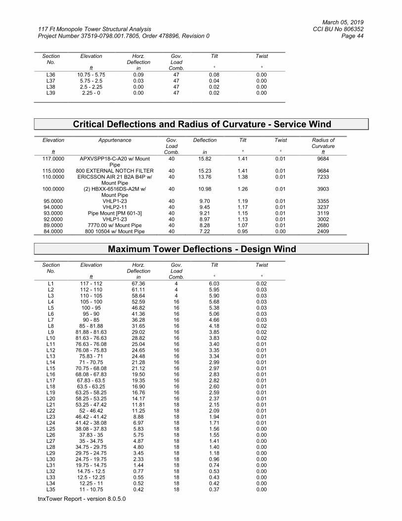
March 05, 2019 117 Ft Monopole Tower Structural Analysis CCI BU No 806352 Project Number 37519-0798.001.7805, Order 478896, Revision 0 Page 44
tnxTower Report - version 8.0.5.0
Section No.
Elevation
ft
Horz. Deflection
in
Gov. Load
Comb.
Tilt °
Twist °
L36 10.75 - 5.75 0.09 47 0.08 0.00 L37 5.75 - 2.5 0.03 47 0.04 0.00 L38 2.5 - 2.25 0.00 47 0.02 0.00 L39 2.25 - 0 0.00 47 0.02 0.00
Critical Deflections and Radius of Curvature - Service Wind
Elevation
ft
Appurtenance Gov. Load
Comb.
Deflection
in
Tilt °
Twist °
Radius of Curvature
ft
117.0000 APXVSPP18-C-A20 w/ Mount Pipe
40 15.82 1.41 0.01 9684
115.0000 800 EXTERNAL NOTCH FILTER 40 15.23 1.41 0.01 9684 110.0000 ERICSSON AIR 21 B2A B4P w/
Mount Pipe 40 13.76 1.38 0.01 7233
100.0000 (2) HBXX-6516DS-A2M w/ Mount Pipe
40 10.98 1.26 0.01 3903
95.0000 VHLP1-23 40 9.70 1.19 0.01 3355 94.0000 VHLP2-11 40 9.45 1.17 0.01 3237 93.0000 Pipe Mount [PM 601-3] 40 9.21 1.15 0.01 3119 92.0000 VHLP1-23 40 8.97 1.13 0.01 3002 89.0000 7770.00 w/ Mount Pipe 40 8.28 1.07 0.01 2680 84.0000 800 10504 w/ Mount Pipe 40 7.22 0.95 0.00 2409
Maximum Tower Deflections - Design Wind
Section No.
Elevation
ft
Horz. Deflection
in
Gov. Load
Comb.
Tilt °
Twist °
L1 117 - 112 67.36 4 6.03 0.02 L2 112 - 110 61.11 4 5.95 0.03 L3 110 - 105 58.64 4 5.90 0.03 L4 105 - 100 52.59 16 5.68 0.03 L5 100 - 95 46.82 16 5.38 0.03 L6 95 - 90 41.36 16 5.06 0.03 L7 90 - 85 36.28 16 4.66 0.03 L8 85 - 81.88 31.65 16 4.18 0.02 L9 81.88 - 81.63 29.02 16 3.85 0.02
L10 81.63 - 76.63 28.82 16 3.83 0.02 L11 76.63 - 76.08 25.04 16 3.40 0.01 L12 76.08 - 75.83 24.65 16 3.35 0.01 L13 75.83 - 71 24.48 16 3.34 0.01 L14 71 - 70.75 21.28 16 2.99 0.01 L15 70.75 - 68.08 21.12 16 2.97 0.01 L16 68.08 - 67.83 19.50 16 2.83 0.01 L17 67.83 - 63.5 19.35 16 2.82 0.01 L18 63.5 - 63.25 16.90 16 2.60 0.01 L19 63.25 - 58.25 16.76 16 2.59 0.01 L20 58.25 - 53.25 14.17 16 2.37 0.01 L21 53.25 - 47.42 11.81 18 2.15 0.01 L22 52 - 46.42 11.25 18 2.09 0.01 L23 46.42 - 41.42 8.88 18 1.94 0.01 L24 41.42 - 38.08 6.97 18 1.71 0.01 L25 38.08 - 37.83 5.83 18 1.56 0.00 L26 37.83 - 35 5.75 18 1.55 0.00 L27 35 - 34.75 4.87 18 1.41 0.00 L28 34.75 - 29.75 4.80 18 1.40 0.00 L29 29.75 - 24.75 3.45 18 1.18 0.00 L30 24.75 - 19.75 2.33 18 0.96 0.00 L31 19.75 - 14.75 1.44 18 0.74 0.00 L32 14.75 - 12.5 0.77 18 0.53 0.00 L33 12.5 - 12.25 0.55 18 0.43 0.00 L34 12.25 - 11 0.52 18 0.42 0.00 L35 11 - 10.75 0.42 18 0.37 0.00

March 05, 2019 117 Ft Monopole Tower Structural Analysis CCI BU No 806352 Project Number 37519-0798.001.7805, Order 478896, Revision 0 Page 45
tnxTower Report - version 8.0.5.0
Section No.
Elevation
ft
Horz. Deflection
in
Gov. Load
Comb.
Tilt °
Twist °
L36 10.75 - 5.75 0.40 18 0.36 0.00 L37 5.75 - 2.5 0.11 18 0.19 0.00 L38 2.5 - 2.25 0.02 18 0.08 0.00 L39 2.25 - 0 0.02 18 0.07 0.00
Critical Deflections and Radius of Curvature - Design Wind
Elevation
ft
Appurtenance Gov. Load
Comb.
Deflection
in
Tilt °
Twist °
Radius of Curvature
ft
117.0000 APXVSPP18-C-A20 w/ Mount Pipe
4 67.36 6.03 0.02 2413
115.0000 800 EXTERNAL NOTCH FILTER 4 64.86 6.00 0.03 2413 110.0000 ERICSSON AIR 21 B2A B4P w/
Mount Pipe 4 58.64 5.90 0.03 1783
100.0000 (2) HBXX-6516DS-A2M w/ Mount Pipe
16 46.82 5.38 0.03 937
95.0000 VHLP1-23 16 41.36 5.06 0.03 799 94.0000 VHLP2-11 16 40.31 4.99 0.03 769 93.0000 Pipe Mount [PM 601-3] 16 39.28 4.91 0.03 741 92.0000 VHLP1-23 16 38.26 4.83 0.03 713 89.0000 7770.00 w/ Mount Pipe 16 35.31 4.57 0.02 636 84.0000 800 10504 w/ Mount Pipe 16 30.78 4.07 0.02 571
Compression Checks Pole Design Data
Section
No. Elevation
ft
Size
L
ft
Lu
ft
Kl/r
A
in2
Pu
K
L1 117 - 112 (1) TP15.4886x14.36x0.1875 5.0000 0.0000 0.0 9.2380 -1.62 L2 112 - 110 (2) TP15.94x15.4886x0.1875 2.0000 0.0000 0.0 9.5106 -1.69 L3 110 - 105 (3) TP17.07x15.94x0.1875 5.0000 0.0000 0.0 10.192
8 -3.95
L4 105 - 100 (4) TP18.2x17.07x0.1875 5.0000 0.0000 0.0 10.8750
-4.24
L5 100 - 95 (5) TP19.3221x18.2x0.25 5.0000 0.0000 0.0 15.3530
-7.91
L6 95 - 90 (6) TP20.4442x19.3221x0.25 5.0000 0.0000 0.0 16.2563
-8.68
L7 90 - 85 (7) TP21.5663x20.4442x0.25 5.0000 0.0000 0.0 17.1596
-13.30
L8 85 - 81.88 (8) TP22.2665x21.5663x0.25 3.1200 0.0000 0.0 17.7233
-14.09
L9 81.88 - 81.63 (9)
TP22.3226x22.2665x0.35 0.2500 0.0000 0.0 24.7631
-14.16
L10 81.63 - 76.63 (10)
TP23.4447x22.3226x0.3563
5.0000 0.0000 0.0 26.4853
-15.12
L11 76.63 - 76.08 (11)
TP23.5681x23.4447x0.3563
0.5500 0.0000 0.0 26.6269
-15.24
L12 76.08 - 75.83 (12)
TP23.6242x23.5681x0.4625
0.2500 0.0000 0.0 34.4936
-15.30
L13 75.83 - 71 (13)
TP24.7082x23.6242x0.4563
4.8300 0.0000 0.0 35.6291
-16.41
L14 71 - 70.75 (14)
TP24.7643x24.7082x0.675
0.2500 0.0000 0.0 52.3581
-16.50
L15 70.75 - 68.08 (15)
TP25.3635x24.7643x0.6625
2.6700 0.0000 0.0 52.6934
-17.25
L16 68.08 - 67.83 (16)
TP25.4196x25.3635x0.7125
0.2500 0.0000 0.0 56.6842
-17.33
L17 67.83 - 63.5 (17)
TP26.3913x25.4196x0.6875
4.3300 0.0000 0.0 56.9018
-18.48
L18 63.5 - 63.25 (18)
TP26.4474x26.3913x0.9 0.2500 0.0000 0.0 74.0365
-18.57
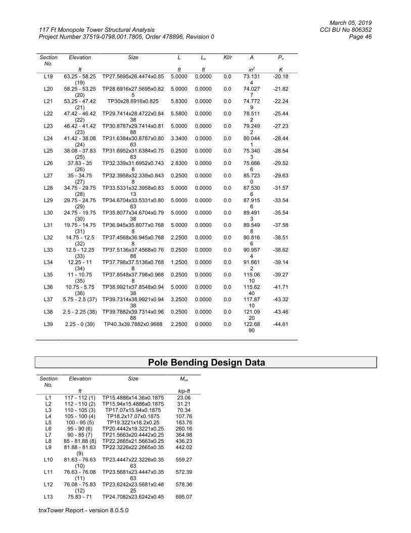
March 05, 2019 117 Ft Monopole Tower Structural Analysis CCI BU No 806352 Project Number 37519-0798.001.7805, Order 478896, Revision 0 Page 46
tnxTower Report - version 8.0.5.0
Section No.
Elevation
ft
Size
L
ft
Lu
ft
Kl/r
A
in2
Pu
K
L19 63.25 - 58.25 (19)
TP27.5695x26.4474x0.85 5.0000 0.0000 0.0 73.1314
-20.18
L20 58.25 - 53.25 (20)
TP28.6916x27.5695x0.825
5.0000 0.0000 0.0 74.0277
-21.82
L21 53.25 - 47.42 (21)
TP30x28.6916x0.825 5.8300 0.0000 0.0 74.7729
-22.24
L22 47.42 - 46.42 (22)
TP29.7414x28.4722x0.8438
5.5800 0.0000 0.0 78.5112
-25.44
L23 46.42 - 41.42 (23)
TP30.8787x29.7414x0.8188
5.0000 0.0000 0.0 79.2492
-27.23
L24 41.42 - 38.08 (24)
TP31.6384x30.8787x0.8063
3.3400 0.0000 0.0 80.0441
-28.44
L25 38.08 - 37.83 (25)
TP31.6952x31.6384x0.7563
0.2500 0.0000 0.0 75.3403
-28.54
L26 37.83 - 35 (26)
TP32.339x31.6952x0.7438
2.8300 0.0000 0.0 75.6666
-29.52
L27 35 - 34.75 (27)
TP32.3958x32.339x0.8438
0.2500 0.0000 0.0 85.7230
-29.63
L28 34.75 - 29.75 (28)
TP33.5331x32.3958x0.8313
5.0000 0.0000 0.0 87.5306
-31.57
L29 29.75 - 24.75 (29)
TP34.6704x33.5331x0.8063
5.0000 0.0000 0.0 87.9156
-33.54
L30 24.75 - 19.75 (30)
TP35.8077x34.6704x0.7938
5.0000 0.0000 0.0 89.4913
-35.54
L31 19.75 - 14.75 (31)
TP36.945x35.8077x0.7688
5.0000 0.0000 0.0 89.5498
-37.58
L32 14.75 - 12.5 (32)
TP37.4568x36.945x0.7688
2.2500 0.0000 0.0 90.8166
-38.51
L33 12.5 - 12.25 (33)
TP37.5136x37.4568x0.7688
0.2500 0.0000 0.0 90.9574
-38.62
L34 12.25 - 11 (34)
TP37.798x37.5136x0.7688
1.2500 0.0000 0.0 91.6612
-39.14
L35 11 - 10.75 (35)
TP37.8548x37.798x0.9688
0.2500 0.0000 0.0 115.0610
-39.27
L36 10.75 - 5.75 (36)
TP38.9921x37.8548x0.9438
5.0000 0.0000 0.0 115.6240
-41.71
L37 5.75 - 2.5 (37) TP39.7314x38.9921x0.9438
3.2500 0.0000 0.0 117.8710
-43.32
L38 2.5 - 2.25 (38) TP39.7882x39.7314x0.9688
0.2500 0.0000 0.0 121.0920
-43.46
L39 2.25 - 0 (39) TP40.3x39.7882x0.9688 2.2500 0.0000 0.0 122.6890
-44.61
Pole Bending Design Data Section
No. Elevation
ft
Size
Mux
kip-ft
L1 117 - 112 (1) TP15.4886x14.36x0.1875 23.06 L2 112 - 110 (2) TP15.94x15.4886x0.1875 31.21 L3 110 - 105 (3) TP17.07x15.94x0.1875 70.34 L4 105 - 100 (4) TP18.2x17.07x0.1875 107.76 L5 100 - 95 (5) TP19.3221x18.2x0.25 183.76 L6 95 - 90 (6) TP20.4442x19.3221x0.25 260.16 L7 90 - 85 (7) TP21.5663x20.4442x0.25 364.98 L8 85 - 81.88 (8) TP22.2665x21.5663x0.25 436.23 L9 81.88 - 81.63
(9) TP22.3226x22.2665x0.35 442.02
L10 81.63 - 76.63 (10)
TP23.4447x22.3226x0.3563
559.27
L11 76.63 - 76.08 (11)
TP23.5681x23.4447x0.3563
572.39
L12 76.08 - 75.83 (12)
TP23.6242x23.5681x0.4625
578.36
L13 75.83 - 71 TP24.7082x23.6242x0.45 695.07

March 05, 2019 117 Ft Monopole Tower Structural Analysis CCI BU No 806352 Project Number 37519-0798.001.7805, Order 478896, Revision 0 Page 47
tnxTower Report - version 8.0.5.0
Section No.
Elevation
ft
Size
Mux
kip-ft
(13) 63 L14 71 - 70.75
(14) TP24.7643x24.7082x0.67
5 701.18
L15 70.75 - 68.08 (15)
TP25.3635x24.7643x0.6625
766.88
L16 68.08 - 67.83 (16)
TP25.4196x25.3635x0.7125
773.07
L17 67.83 - 63.5 (17)
TP26.3913x25.4196x0.6875
881.49
L18 63.5 - 63.25 (18)
TP26.4474x26.3913x0.9 887.83
L19 63.25 - 58.25 (19)
TP27.5695x26.4474x0.85 1015.93
L20 58.25 - 53.25 (20)
TP28.6916x27.5695x0.825
1147.05
L21 53.25 - 47.42 (21)
TP30x28.6916x0.825 1180.33
L22 47.42 - 46.42 (22)
TP29.7414x28.4722x0.8438
1331.40
L23 46.42 - 41.42 (23)
TP30.8787x29.7414x0.8188
1470.01
L24 41.42 - 38.08 (24)
TP31.6384x30.8787x0.8063
1564.18
L25 38.08 - 37.83 (25)
TP31.6952x31.6384x0.7563
1571.27
L26 37.83 - 35 (26)
TP32.339x31.6952x0.7438
1652.10
L27 35 - 34.75 (27)
TP32.3958x32.339x0.8438
1659.28
L28 34.75 - 29.75 (28)
TP33.5331x32.3958x0.8313
1804.36
L29 29.75 - 24.75 (29)
TP34.6704x33.5331x0.8063
1952.12
L30 24.75 - 19.75 (30)
TP35.8077x34.6704x0.7938
2102.58
L31 19.75 - 14.75 (31)
TP36.945x35.8077x0.7688
2255.55
L32 14.75 - 12.5 (32)
TP37.4568x36.945x0.7688
2325.15
L33 12.5 - 12.25 (33)
TP37.5136x37.4568x0.7688
2332.92
L34 12.25 - 11 (34)
TP37.798x37.5136x0.7688
2371.81
L35 11 - 10.75 (35)
TP37.8548x37.798x0.9688
2379.61
L36 10.75 - 5.75 (36)
TP38.9921x37.8548x0.9438
2536.82
L37 5.75 - 2.5 (37) TP39.7314x38.9921x0.9438
2640.33
L38 2.5 - 2.25 (38) TP39.7882x39.7314x0.9688
2648.33
L39 2.25 - 0 (39) TP40.3x39.7882x0.9688 2720.67
Pole Shear Design Data Section
No. Elevation
ft
Size
Actual Vu
K
L1 117 - 112 (1) TP15.4886x14.36x0.1875 4.01 L2 112 - 110 (2) TP15.94x15.4886x0.1875 4.14 L3 110 - 105 (3) TP17.07x15.94x0.1875 7.30 L4 105 - 100 (4) TP18.2x17.07x0.1875 7.68 L5 100 - 95 (5) TP19.3221x18.2x0.25 14.61 L6 95 - 90 (6) TP20.4442x19.3221x0.25 15.71 L7 90 - 85 (7) TP21.5663x20.4442x0.25 22.33

March 05, 2019 117 Ft Monopole Tower Structural Analysis CCI BU No 806352 Project Number 37519-0798.001.7805, Order 478896, Revision 0 Page 48
tnxTower Report - version 8.0.5.0
Section No.
Elevation
ft
Size
Actual Vu
K
L8 85 - 81.88 (8) TP22.2665x21.5663x0.25 23.17 L9 81.88 - 81.63
(9) TP22.3226x22.2665x0.35 23.18
L10 81.63 - 76.63 (10)
TP23.4447x22.3226x0.3563
23.84
L11 76.63 - 76.08 (11)
TP23.5681x23.4447x0.3563
23.89
L12 76.08 - 75.83 (12)
TP23.6242x23.5681x0.4625
23.92
L13 75.83 - 71 (13)
TP24.7082x23.6242x0.4563
24.44
L14 71 - 70.75 (14)
TP24.7643x24.7082x0.675
24.47
L15 70.75 - 68.08 (15)
TP25.3635x24.7643x0.6625
24.78
L16 68.08 - 67.83 (16)
TP25.4196x25.3635x0.7125
24.81
L17 67.83 - 63.5 (17)
TP26.3913x25.4196x0.6875
25.31
L18 63.5 - 63.25 (18)
TP26.4474x26.3913x0.9 25.34
L19 63.25 - 58.25 (19)
TP27.5695x26.4474x0.85 25.94
L20 58.25 - 53.25 (20)
TP28.6916x27.5695x0.825
26.55
L21 53.25 - 47.42 (21)
TP30x28.6916x0.825 26.70
L22 47.42 - 46.42 (22)
TP29.7414x28.4722x0.8438
27.44
L23 46.42 - 41.42 (23)
TP30.8787x29.7414x0.8188
28.01
L24 41.42 - 38.08 (24)
TP31.6384x30.8787x0.8063
28.39
L25 38.08 - 37.83 (25)
TP31.6952x31.6384x0.7563
28.41
L26 37.83 - 35 (26)
TP32.339x31.6952x0.7438
28.72
L27 35 - 34.75 (27)
TP32.3958x32.339x0.8438
28.74
L28 34.75 - 29.75 (28)
TP33.5331x32.3958x0.8313
29.29
L29 29.75 - 24.75 (29)
TP34.6704x33.5331x0.8063
29.82
L30 24.75 - 19.75 (30)
TP35.8077x34.6704x0.7938
30.36
L31 19.75 - 14.75 (31)
TP36.945x35.8077x0.7688
30.83
L32 14.75 - 12.5 (32)
TP37.4568x36.945x0.7688
31.04
L33 12.5 - 12.25 (33)
TP37.5136x37.4568x0.7688
31.05
L34 12.25 - 11 (34)
TP37.798x37.5136x0.7688
31.18
L35 11 - 10.75 (35)
TP37.8548x37.798x0.9688
31.19
L36 10.75 - 5.75 (36)
TP38.9921x37.8548x0.9438
31.69
L37 5.75 - 2.5 (37) TP39.7314x38.9921x0.9438
32.01
L38 2.5 - 2.25 (38) TP39.7882x39.7314x0.9688
32.03
L39 2.25 - 0 (39) TP40.3x39.7882x0.9688 32.26
March 05, 2019 117 Ft Monopole Tower Structural Analysis CCI BU No 806352 Project Number 37519-0798.001.7805, Order 478896, Revision 0 Page 49
tnxTower Report - version 8.0.5.0
APPENDIX B
BASE LEVEL DRAWING

March 05, 2019 117 Ft Monopole Tower Structural Analysis CCI BU No 806352 Project Number 37519-0798.001.7805, Order 478896, Revision 0 Page 50
tnxTower Report - version 8.0.5.0
March 05, 2019 117 Ft Monopole Tower Structural Analysis CCI BU No 806352 Project Number 37519-0798.001.7805, Order 478896, Revision 0 Page 51
tnxTower Report - version 8.0.5.0
APPENDIX C
ADDITIONAL CALCULATIONS
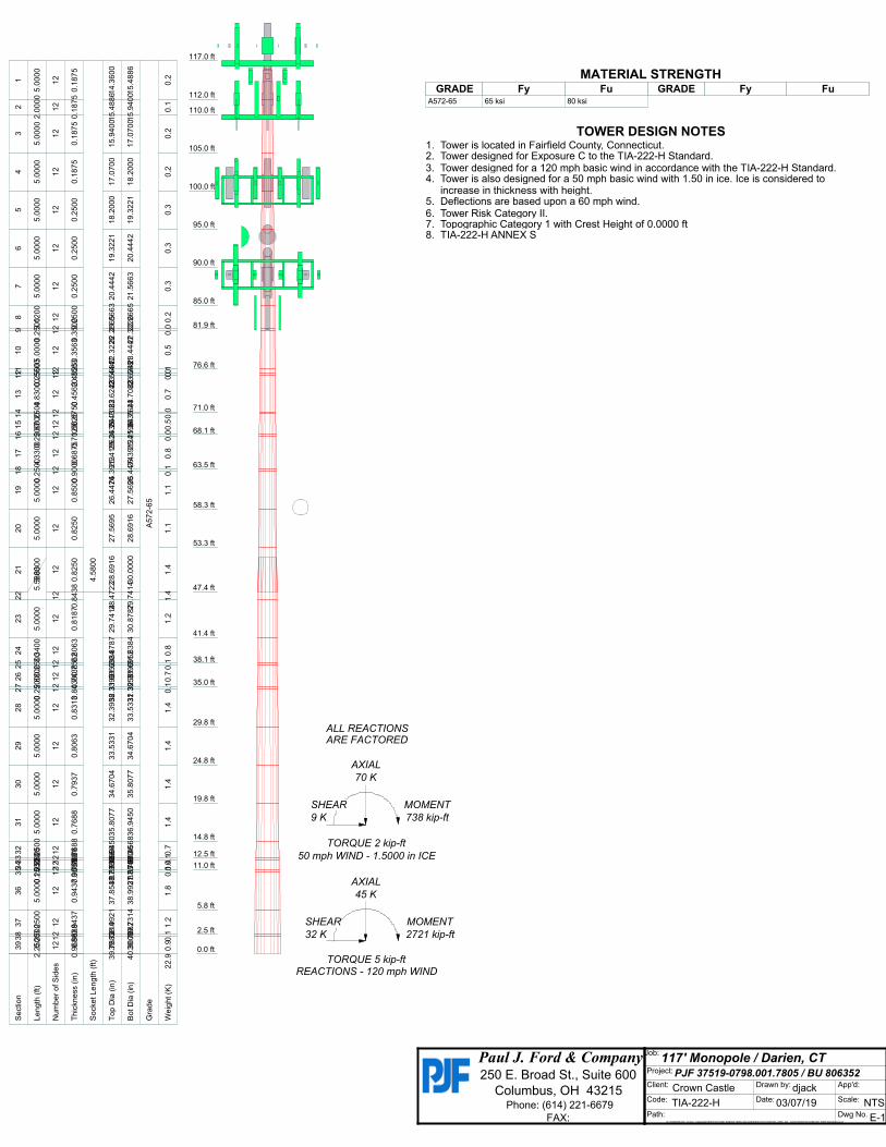
Paul J. Ford & Company 250 E. Broad St., Suite 600
Columbus, OH 43215 Phone: (614) 221-6679
FAX:
Job: 117' Monopole / Darien, CT
Project: PJF 37519-0798.001.7805 / BU 806352 Client: Crown Castle Drawn by: djack App'd:
Code: TIA-222-H Date: 03/07/19 Scale: NTS Path:
G:\TOWER\375_Crown_Castle\2019\37519-0798_806352_BRG 302 943052\37519-0798.001.7805_SA_1704178\37519-0798.001.7805 Reinforced.eri
Dwg No. E-1
117.0 ft
112.0 ft
110.0 ft
105.0 ft
100.0 ft
95.0 ft
90.0 ft
85.0 ft
81.9 ft
76.6 ft
71.0 ft
68.1 ft
63.5 ft
58.3 ft
53.3 ft
47.4 ft
41.4 ft
38.1 ft
35.0 ft
29.8 ft
24.8 ft
19.8 ft
14.8 ft
12.5 ft
11.0 ft
5.8 ft
2.5 ft
0.0 ft
REACTIONS - 120 mph WINDTORQUE 5 kip-ft
32 K
SHEAR
2721 kip-ft
MOMENT
45 K
AXIAL
50 mph WIND - 1.5000 in ICE
TORQUE 2 kip-ft
9 K
SHEAR
738 kip-ft
MOMENT
70 K
AXIAL
ARE FACTOREDALL REACTIONS
S
ectio
n1
23
45
67
89
10
11
12
13
14
15
16
17
18
19
20
21
22
23
24
25
26
27
28
29
30
31
32
33
34
35
36
37
38
39
L
en
gth
(ft)
5.0
00
02
.00
00
5.0
00
05
.00
00
5.0
00
05
.00
00
5.0
00
03
.12
00
0.2
50
05
.00
00
0.5
50
00
.25
00
4.8
30
00
.25
00
2.6
70
00
.25
00
4.3
30
00
.25
00
5.0
00
05
.00
00
5.8
30
05
.58
00
5.0
00
03
.34
00
0.2
50
02
.83
00
0.2
50
05
.00
00
5.0
00
05
.00
00
5.0
00
02
.25
00
0.2
50
01
.25
00
0.2
50
05
.00
00
3.2
50
00
.25
00
2.2
50
0
N
um
be
r o
f S
ide
s1
21
21
21
21
21
21
21
21
21
21
21
21
21
21
21
21
21
21
21
21
21
21
21
21
21
21
21
21
21
21
21
21
21
21
21
21
21
21
2
T
hic
kn
ess (
in)
0.1
87
50
.18
75
0.1
87
50
.18
75
0.2
50
00
.25
00
0.2
50
00
.25
00
0.3
50
00
.35
63
0.3
56
30
.46
25
0.4
56
20
.67
50
0.6
62
50
.71
25
0.6
87
50
.90
00
0.8
50
00
.82
50
0.8
25
00
.84
38
0.8
18
70
.80
63
0.7
56
20
.74
38
0.8
43
80
.83
13
0.8
06
30
.79
37
0.7
68
80
.76
88
0.7
68
80
.76
88
0.9
68
80
.94
37
0.9
43
70
.96
88
0.9
68
8
S
ocke
t L
en
gth
(ft)
4.5
80
0
T
op
Dia
(in
)1
4.3
60
01
5.4
88
61
5.9
40
01
7.0
70
01
8.2
00
01
9.3
22
12
0.4
44
22
1.5
66
32
2.2
66
52
2.3
22
62
3.4
44
72
3.5
68
12
3.6
24
22
4.7
08
22
4.7
64
32
5.3
63
52
5.4
19
62
6.3
91
32
6.4
47
42
7.5
69
52
8.6
91
62
8.4
72
22
9.7
41
43
0.8
78
73
1.6
38
43
1.6
95
23
2.3
39
03
2.3
95
83
3.5
33
13
4.6
70
43
5.8
07
73
6.9
45
03
7.4
56
83
7.5
13
63
7.7
98
03
7.8
54
83
8.9
92
13
9.7
31
43
9.7
88
2
B
ot D
ia (
in)
15
.48
86
15
.94
00
17
.07
00
18
.20
00
19
.32
21
20
.44
42
21
.56
63
22
.26
65
22
.32
26
23
.44
47
23
.56
81
23
.62
42
24
.70
82
24
.76
43
25
.36
35
25
.41
96
26
.39
13
26
.44
74
27
.56
95
28
.69
16
30
.00
00
29
.74
14
30
.87
87
31
.63
84
31
.69
52
32
.33
90
32
.39
58
33
.53
31
34
.67
04
35
.80
77
36
.94
50
37
.45
68
37
.51
36
37
.79
80
37
.85
48
38
.99
21
39
.73
14
39
.78
82
40
.30
00
G
rad
eA
57
2-6
5
W
eig
ht (K
)0
.20
.10
.20
.20
.30
.30
.30
.20
.00
.50
.10
.00
.70
.00
.50
.00
.80
.11
.11
.11
.41
.41
.20
.80
.10
.70
.11
.41
.41
.41
.40
.70
.10
.40
.11
.81
.20
.10
.92
2.9
MATERIAL STRENGTHGRADE GRADEFy FyFu Fu
A572-65 65 ksi 80 ksi
TOWER DESIGN NOTES1. Tower is located in Fairfield County, Connecticut.2. Tower designed for Exposure C to the TIA-222-H Standard.3. Tower designed for a 120 mph basic wind in accordance with the TIA-222-H Standard.4. Tower is also designed for a 50 mph basic wind with 1.50 in ice. Ice is considered to
increase in thickness with height.5. Deflections are based upon a 60 mph wind.6. Tower Risk Category II.7. Topographic Category 1 with Crest Height of 0.0000 ft8. TIA-222-H ANNEX S

H
Site BU:
Work Order:
Pole Geometry Copyright © 2019 Crown Castle
1
2
3
4
Reinforcement Configuration
1 2 3 4 5 6 7 8 9 10 11 12
1 o o o
2 o o o
3 o o o
4 o o o
5 o o o
6 o
7 o o
8 o o o
9 o o o
10 c
11 c c
12 o o o
13 c c c
1415
Reinforcement Details
1
2
3
4
5
6
7
8
9
10
11
12
13
plate
plate
plate
plate
plate
2
3
12.50
35
63.5
71
35
49
38.08
38.08
68.08
81.8868.08
0
35
51.5
0
35
12.5
2.5
38.08
0 11 plate FP 1.25 x 4.5_1 3
0 2.5 plate 2
68.08 76.08 plate CCI-040075; (1) (1.1875)_1 3
FP 1.25 x 5.25_1
1.25 4.5 5.625 2.25 n/a n/a 0.000 5.625 0.0000
4 0.75 3 0.375 n/a n/a 16.000 2.063 1.1875
1.25 5.25 6.5625 2.625 n/a n/a 0.000 6.563 0.0000
1.25 5.25 6.5625 2.625 n/a n/a 0.000 6.563 0.0000
4.5 1 4.5 0.5 n/a n/a 19.250 3.250 1.1875
6 1 6 0.5 n/a n/a 16.000 4.750 1.1875
4.5 1 4.5 0.5 n/a n/a 19.250 3.250 1.1875
4.5 1 4.5 0.5 n/a n/a 19.250 3.250 1.1875
4 0.75 3 0.375 n/a n/a 16.000 2.063 1.1875
4.5 1 4.5 0.5 n/a n/a 19.250
1
1
117
110
100
3
3
3
3
3
1
plate
plate
plate
Bottom Effective
Elevation (ft) Type
plate
plate
Top Effective
Elevation (ft)
Pole Face to
Centroid (in)
0.5
0.5
0.5
Gross Area (in2)
6
4.5
4.5
B (in)
6
4.5
4.5
H (in)
Reinforcement
Material
A572-65
A572-65
A572-65
A572-65
A572-65
A572-65
A572-65
A572-65
A572-65
A572-65
A572-65
A572-65
A572-65
Pole Material
15.94
52
7
10
52.58
52
0.1875
18.2 0.1875
0.25
0.34375
14.36
15.94
18.20
28.47
Top Diameter (in)
Pole Height Above
Base (ft) Section Length (ft)
Lap Splice Length
(ft)
A572-6512
12
0
0
30
40.3
4.58
0
12
12
1
A572-65
A572-65
A572-65
MS-450; (1) (1.1875)_2
1.1875
1.1875
Auto
Auto
Auto
Bottom Diameter
(in)
Number
3
1
Bottom
Termination
Length (in)
Top
Termination
Length (in) Lu (in)
n/a
CCI-045100; (1) (1.1875)_1
CCI-040075; (1) (1.1875)_1
CCI-045100; (1) (1.1875)_1
FP 1.25 x 5.25_1
806352
CCI-060100; (1) (1.1875)_1
MS-600; (1) (1.1875)_1
MS-450; (1) (1.1875)_1
CCI-045100; (1) (1.1875)_1
3.250 1.1875
Model
Number of Sides
Net Area (in2)
4.750
n/a n/a
Bend Radius (in)
Auto
Bolt Hole Size (in)
1.1875
Wall Thickness (in)
3.250
n/a n/a 3.250
n/a 16.250
12.000
21.000
CCI-045100; (1) (1.1875)_1
per TIA-222-
CCIpole - version 4.3.0 Analysis Date: 3/7/2019Page 1

TNX Geometry Input
5
1 -
2 -
3 -
4 -
5 -
6 -
7 -
8 -
9 -
10 -
11 -
12 -
13 -
14 -
15 -
16 -
17 -
18 -
19 -
20 -
21 -
22 -
23 -
24 -
25 -
26 -
27 -
28 -
29 -
30 -
31 -
32 -
33 -
34 -
35 -
36 -
37 -
38 -
39 -
0 12 A572-65
0.924
0.913
0.923
0.916
1.068
0.914
0.924
0.917
A572-65
Weight
Multiplier
1.000
1.000
1.000
1.263
1.000
1.000
1.000
1.000
1.000
0.942
0.956
0.949
0.970
0.966
0.939
0.939
0.944
0.940
0.935
0.945
0.894
1.199
1.185
1.065
0.917
0.918
0.912
0.931
1.215
1.213
A572-65
0.7125
0.938
32.396
5 12 14.360
Tapered Pole
Grade
A572-65
A572-65
A572-65
A572-65
A572-65
5 12
0
Section Height (ft) Section Length (ft)
Lap Splice Length
(ft) Number of Sides Top Diameter (in)
Bottom Diameter
(in)
15.489117 112
112 110
105
100
110
105
Increment (ft):
0.1875
0 12 15.489 15.940
Wall Thickness (in)
0.1875
5 12 15.940 17.070 0.1875
2
0.18755
12 19.322 20.444 0.25
17.070 18.200
18.200 19.322 0.25
12
A572-65
5 12 20.444 21.566 0.25 A572-65
5
22.323 0.35 A572-65
3.12 12 21.566 22.266 0.25
5 12 22.323 23.445
A572-65
0.25 12 22.266
0.55 12 23.445 23.568 0.35625
0.35625 A572-65
A572-65
0.4625 A572-65
12 23.624 24.708 0.45625
12 23.568 23.624
A572-65
0.25
0.25 12 24.708 24.764 0.675 A572-65
4.83
71 70.75
2.67 12 24.76470.75 68.08
0.6875 A572-65
25.363 0.6625
12 25.363 25.42068.08 67.83
67.83 63.5 4.33 12 25.420 26.391
5 12
0.25
0.25 12
26.447 27.570 0.85
12 27.570 28.692
0.9 A572-65
A572-65
0.825 A572-65
29.741 0.84375 A572-65
5.83 4.58 12 28.692 30.000 0.825
26.391 26.447
3.34
2.83 12 31.695 32.339
12 32.396 33.533
5 12 29.741
A572-65
5
5.58 12 28.472
30.879 0.81875
12 30.879 31.638
A572-65
0.80625 A572-65
34.75 29.75
29.75 24.75
0.25 12 31.638 31.695 0.75625 A572-65
A572-65
5
5 12 34.670
0.25 12 32.339
0.74375 A572-65
A572-65
0.83125 A572-65
37.798
A572-65
0.76875 A572-65
0.79375 A572-65
5 12 33.533 34.670 0.80625
2.25
1.25 12 37.514
5 12 35.808 36.945 0.76875
12 36.945 37.457
0.25
12 37.855 38.992
A572-6512
0.25 12
0.84375
35.808
0.76875 A572-65
A572-65
0.94375 A572-65
37.855 0.96875
5
37.798
37.457 37.514 0.76875
2.25 12 39.788
A572-65
0.96875 A572-65
39.731 0.94375
40.300 0.96875 A572-65
0.25 12 39.731 39.788
3.25 12 38.992
100 95
95 90
90 85
85 81.88
81.88 81.63
81.63 76.63
76.63 76.08
76.08 75.83
75.83 71
63.25 58.25
63.5 63.25
58.25 53.25
53.25 52
46.42 41.42
52 46.42
41.42 38.08
38.08 37.83
35 34.75
37.83 35
19.75 14.75
24.75 19.75
14.75 12.5
12.5 12.25
11 10.75
10.75 5.75
5.75 2.5
2.25 0
2.5 2.25
12.25 11
CCIpole - version 4.3.0 Page 2 Analysis Date: 3/7/2019

TNX Section Forces
5
Pu (K)
Mux (kip-
ft) Vu (K)
### 1 - 1.62 23.06 4.01
### 2 - 1.69 31.21 4.14
### 3 - 3.95 70.34 7.30
### 4 - 4.24 107.76 7.68
### 5 - 7.91 183.76 14.61
### 6 - 8.68 260.19 15.71
### 7 - 13.30 364.98 22.33
### 8 - 14.09 436.23 23.17
### 9 - 14.16 442.02 23.18
### 10 - 15.12 559.27 23.84
### 11 - 15.24 572.39 23.89
### 12 - 15.30 578.36 23.92
### 13 - 16.41 695.07 24.44
### 14 - 16.50 701.18 24.47
### 15 - 17.25 766.88 24.78
### 16 - 17.33 773.07 24.81
### 17 - 18.48 881.49 25.31
### 18 - 18.57 887.82 25.34
### 19 - 20.18 1015.92 25.94
### 20 - 21.82 1147.05 26.55
### 21 - 22.24 1180.33 26.70
### 22 - 25.44 1331.40 27.44
### 23 - 27.23 1470.01 28.01
### 24 - 28.44 1564.17 28.39
### 25 - 28.54 1571.27 28.41
### 26 - 29.52 1652.10 28.72
### 27 - 29.63 1659.28 28.74
### 28 - 31.57 1804.36 29.29
### 29 - 33.54 1952.12 29.82
### 30 - 35.54 2102.58 30.36
### 31 - 37.58 2255.55 30.83
### 32 - 38.51 2325.15 31.04
### 33 - 38.62 2332.91 31.05
### 34 - 39.14 2371.81 31.18
### 35 - 39.27 2379.61 31.19
### 36 - 41.71 2536.82 31.69
### 37 - 43.32 2640.33 32.01
### 38 - 43.46 2648.34 32.03
### 39 - 44.61 2720.66 32.260
TNX Output
Section Height (ft)
117 112
112 110
105
100
110
105
Increment (ft):
71 70.75
70.75 68.08
68.08 67.83
67.83 63.5
34.75 29.75
29.75 24.75
100 95
95 90
90 85
85 81.88
81.88 81.63
81.63 76.63
76.63 76.08
76.08 75.83
75.83 71
63.25 58.25
63.5 63.25
58.25 53.25
53.25 52
46.42 41.42
52 46.42
41.42 38.08
38.08 37.83
35 34.75
37.83 35
19.75 14.75
24.75 19.75
14.75 12.5
12.5 12.25
11 10.75
10.75 5.75
5.75 2.5
2.25 0
2.5 2.25
12.25 11
CCIpole - version 4.3.0 Analysis Date: 3/7/2019Page 3
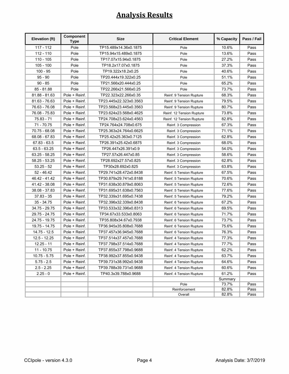
Analysis Results
Reinforcement 82.8% Pass
73.7% Pass
Overall 82.8% Pass
Summary
Pole 73.7% Pass
Pole TP18.2x17.07x0.1875 Pole 37.3% Pass
40.6%
Pole TP22.266x21.566x0.25 Pole
Pole + Reinf. TP23.624x23.568x0.4625 Reinf. 12 Tension Rupture
Pole + Reinf. TP25.42x25.363x0.7125 Reinf. 3 Compression
Pole + Reinf. TP28.692x27.57x0.825 Reinf. 3 Compression
Pole + Reinf. TP31.638x30.879x0.8063 Reinf. 5 Tension Rupture
Pole + Reinf. TP33.533x32.396x0.8313 Reinf. 6 Tension Rupture
Pole + Reinf. TP37.457x36.945x0.7688 Reinf. 6 Tension Rupture
Pole + Reinf. TP38.992x37.855x0.9438 Reinf. 4 Tension Rupture
Pole
Pole
Component
TypeSize Critical Element % Capacity Pass / Fail
10.6% PassPole TP15.489x14.36x0.1875 Pole
Pole TP15.94x15.489x0.1875 Pole 13.6% Pass
27.2% PassTP17.07x15.94x0.1875 Pole
Pole 51.1% Pass
Pass
Pole TP21.566x20.444x0.25 Pole 65.2% Pass
105 - 100
100 - 95
95 - 90
90 - 85
Pole
TP19.322x18.2x0.25 Pole
TP20.444x19.322x0.25
Pole + Reinf. TP22.323x22.266x0.35 Reinf. 9 Tension Rupture 68.3% Pass
Pole + Reinf. TP23.445x22.323x0.3563 Reinf. 9 Tension Rupture 79.5% Pass
Pole + Reinf. TP23.568x23.445x0.3563 Reinf. 9 Tension Rupture 80.7% Pass
73.8% Pass
Pole + Reinf. TP24.708x23.624x0.4563 Reinf. 12 Tension Rupture 82.8% Pass
Pole + Reinf. TP24.764x24.708x0.675 Reinf. 3 Compression 67.3% Pass
Pole + Reinf. TP25.363x24.764x0.6625 Reinf. 3 Compression 71.1% Pass
62.8% Pass
Pole + Reinf. TP26.391x25.42x0.6875 Reinf. 3 Compression 68.0% Pass
Pole + Reinf. TP26.447x26.391x0.9 Reinf. 3 Compression 54.0% Pass
Pole + Reinf. TP27.57x26.447x0.85 Reinf. 3 Compression 58.6% Pass
62.8% Pass
Pole + Reinf. TP30x28.692x0.825 Reinf. 3 Compression 63.8% Pass
Pole + Reinf. TP29.741x28.472x0.8438 Reinf. 5 Tension Rupture 67.5% Pass
Pole + Reinf. TP30.879x29.741x0.8188 Reinf. 5 Tension Rupture 70.6% Pass
72.6% Pass
Pole + Reinf. TP31.695x31.638x0.7563 Reinf. 5 Tension Rupture 77.6% Pass
Pole + Reinf. TP32.339x31.695x0.7438 Reinf. 5 Tension Rupture 79.2% Pass
Pole + Reinf. TP32.396x32.339x0.8438 Reinf. 6 Tension Rupture 67.2% Pass
69.5% Pass
Pole + Reinf. TP34.67x33.533x0.8063 Reinf. 6 Tension Rupture 71.7% Pass
Pole + Reinf. TP35.808x34.67x0.7938 Reinf. 6 Tension Rupture 73.7% Pass
Pole + Reinf. TP36.945x35.808x0.7688 Reinf. 6 Tension Rupture 75.6% Pass
76.3% Pass
Pole + Reinf. TP37.514x37.457x0.7688 Reinf. 4 Tension Rupture 77.3% Pass
Pole + Reinf. TP37.798x37.514x0.7688 Reinf. 4 Tension Rupture 77.7% Pass
Pole + Reinf. TP37.855x37.798x0.9688 Reinf. 4 Tension Rupture 62.2% Pass
63.7% Pass
Pole + Reinf. TP39.731x38.992x0.9438 Reinf. 4 Tension Rupture 64.6% Pass
Pole + Reinf. TP39.788x39.731x0.9688 Reinf. 4 Tension Rupture 60.6% Pass
Pole + Reinf. TP40.3x39.788x0.9688 Reinf. 4 Tension Rupture 61.2% Pass
Elevation (ft)
117 - 112
112 - 110
110 - 105
85 - 81.88
81.88 - 81.63
81.63 - 76.63
76.63 - 76.08
76.08 - 75.83
75.83 - 71
71 - 70.75
70.75 - 68.08
68.08 - 67.83
67.83 - 63.5
63.5 - 63.25
63.25 - 58.25
58.25 - 53.25
53.25 - 52
52 - 46.42
46.42 - 41.42
41.42 - 38.08
38.08 - 37.83
37.83 - 35
35 - 34.75
34.75 - 29.75
29.75 - 24.75
24.75 - 19.75
19.75 - 14.75
14.75 - 12.5
12.5 - 12.25
12.25 - 11
11 - 10.75
10.75 - 5.75
5.75 - 2.5
2.5 - 2.25
2.25 - 0
CCIpole - version 4.3.0 Analysis Date: 3/7/2019Page 4
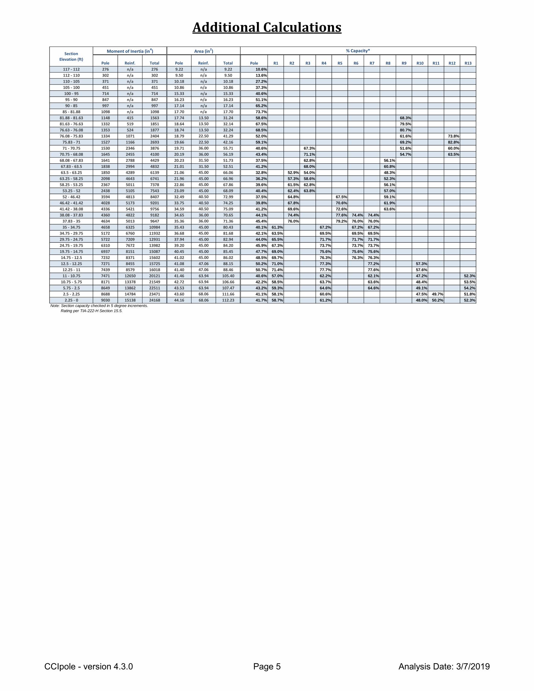
Additional Calculations
Pole R1 R2 R3 R4 R5 R6 R7 R8 R9 R10 R11 R12 R13
117 - 112 10.6%
112 - 110 13.6%
110 - 105 27.2%
105 - 100 37.3%
100 - 95 40.6%
95 - 90 51.1%
90 - 85 65.2%
85 - 81.88 73.7%
81.88 - 81.63 58.6% 68.3%
81.63 - 76.63 67.5% 79.5%
76.63 - 76.08 68.5% 80.7%
76.08 - 75.83 52.0% 61.6% 73.8%
75.83 - 71 59.1% 69.2% 82.8%
71 - 70.75 40.6% 67.3% 51.6% 60.0%
70.75 - 68.08 43.4% 71.1% 54.7% 63.5%
68.08 - 67.83 37.5% 62.8% 56.1%
67.83 - 63.5 41.2% 68.0% 60.8%
63.5 - 63.25 32.8% 52.9% 54.0% 48.3%
63.25 - 58.25 36.2% 57.3% 58.6% 52.3%
58.25 - 53.25 39.6% 61.5% 62.8% 56.1%
53.25 - 52 40.4% 62.4% 63.8% 57.0%
52 - 46.42 37.5% 64.8% 67.5% 59.1%
46.42 - 41.42 39.8% 67.8% 70.6% 61.9%
41.42 - 38.08 41.2% 69.6% 72.6% 63.6%
38.08 - 37.83 44.1% 74.4% 77.6% 74.4% 74.4%
37.83 - 35 45.4% 76.0% 79.2% 76.0% 76.0%
35 - 34.75 40.1% 61.3% 67.2% 67.2% 67.2%
34.75 - 29.75 42.1% 63.5% 69.5% 69.5% 69.5%
29.75 - 24.75 44.0% 65.5% 71.7% 71.7% 71.7%
24.75 - 19.75 45.9% 67.3% 73.7% 73.7% 73.7%
19.75 - 14.75 47.7% 69.0% 75.6% 75.6% 75.6%
14.75 - 12.5 48.5% 69.7% 76.3% 76.3% 76.3%
12.5 - 12.25 50.2% 71.0% 77.3% 77.2% 57.3%
12.25 - 11 50.7% 71.4% 77.7% 77.6% 57.6%
11 - 10.75 40.6% 57.0% 62.2% 62.1% 47.2% 52.3%
10.75 - 5.75 42.2% 58.5% 63.7% 63.6% 48.4% 53.5%
5.75 - 2.5 43.2% 59.3% 64.6% 64.6% 49.1% 54.2%
2.5 - 2.25 41.1% 58.1% 60.6% 47.5% 49.7% 51.8%
2.25 - 0 41.7% 58.7% 61.2% 48.0% 50.2% 52.3%
Note: Section capacity checked in 5 degree increments.
Rating per TIA-222-H Section 15.5.
15.33
16.23
n/a
n/a
9.22
9.50
10.18
10.86
Reinf. Total
Moment of Inertia (in4) Area (in2)
n/a
n/a
n/a
n/a
451 451 10.86
714 714 15.33
Reinf.
n/a
n/a
n/a
n/a
n/a
847 847 16.23
997 997 17.14
371 371 10.18
Pole Total Pole
276 276 9.22
302 302 9.50
1098 1098 17.70
1148 1563 17.74
1332 1851 18.64
1353 1877 18.74
n/a
n/a
n/a
415
519
524
1334 2404 18.79
1527 2693 19.66
1530 3876 19.71
1645 4100 20.19
1641 4429 20.23
1838 4832 21.012994
1071
1166
2346
2455
2788
1850 6139 21.06
2098 6741 21.96
2367 7378 22.86
2438 7543 23.09
3594 8407 32.49
4028 9201 33.75
4289
4643
5011
5105
4813
5173
4336 9756 34.59
4360 9182 34.65
4634 9647 35.36
4658 10984 35.43
5172 11932 36.68
5722 12931 37.94
5421
4822
5013
6325
6760
7209
6310 13982 39.20
6937 15087 40.45
7232 15602 41.02
7271 15725 41.08
7439 16018 41.40
7471 20121 41.46
7672
8151
8371
8455
8579
12650
8171 21549 42.72
8649 22511 43.53
8688 23471 43.60
9030 24168 44.16
13378
13862
14784
15138
n/a 17.14
n/a 17.70
13.50 31.24
13.50 32.14
13.50 32.24
22.50 41.29
22.50 42.16
36.00 55.71
36.00 56.19
31.50 51.73
31.50 52.51
45.00 66.06
45.00 66.96
45.00 67.86
45.00 68.09
40.50 72.99
40.50 74.25
40.50 75.09
36.00 70.65
36.00 71.36
45.00 80.43
45.00 81.68
45.00 82.94
45.00 84.20
45.00 85.45
45.00 86.02
47.06 88.15
47.06 88.46
63.94 105.40
63.94 106.66
63.94 107.47
68.06 111.66
68.06 112.23
% Capacity*Section
Elevation (ft)
CCIpole - version 4.3.0 Analysis Date: 3/7/2019Page 5

Monopole Flange Plate Connection
*TIA-222-H Section 15.5 Applied
Top Plate Data Bottom Plate Data
22" OD x 1.5" Plate (A36; Fy=36 ksi, Fu=58 ksi) 22" OD x 1.5" Plate (A36; Fy=36 ksi, Fu=58 ksi)
Top Stiffener Data Bottom Stiffener Data
N/A N/A
Top Pole Data Bottom Pole Data
15.94" x 0.1875" 12-sided pole (A572-65; Fy=65 ksi, Fu=80 ksi) 15.94" x 0.1875" 12-sided pole (A572-65; Fy=65 ksi, Fu=80 ksi)
Max Load (kips) 7.54
Allowable (kips) 54.54
Stress Rating: 13.2% Pass
Top Plate Capacity Bottom Plate Capacity
2.91 (Flexural) 2.91 (Flexural)
32.40 32.40
8.6% Pass 8.6% Pass
3.1% Pass 3.1% Pass
Elevation = 110 ft.
Order # Axial Force (kips) 2.00
BU # 806352 Applied Loads
Site Name Moment (kip-ft) 31.00
Shear Force (kips) 4.00
TIA-222 Revision H
Bottom Plate - ExternalTop Plate - External
Allowable Stress (ksi): Allowable Stress (ksi):
Connection Properties
Bolt Data
Analysis Results
Bolt Capacity
Max Stress (ksi): Max Stress (ksi):
(10) 1" ø bolts (A325 N; Fy=92 ksi, Fu=120 ksi) on 19.2" BC
Stress Rating: Stress Rating:
Tension Side Stress Rating: Tension Side Stress Rating:
Show image?
Plate Dia.
Shaft Dia.
Pole Shape
Plate Type:
Plate Geometry:
Plate Quantity
Plate Dia. 2
Shaft Dia. 2
Show image?
Plate Dia.
Shaft Dia.
Pole Shape
Plate Type:
Plate Geometry:
Plate Quantity
Plate Dia. 2
Shaft Dia. 2
CCIplate - version 3.6.0 Analysis Date: 3/7/2019
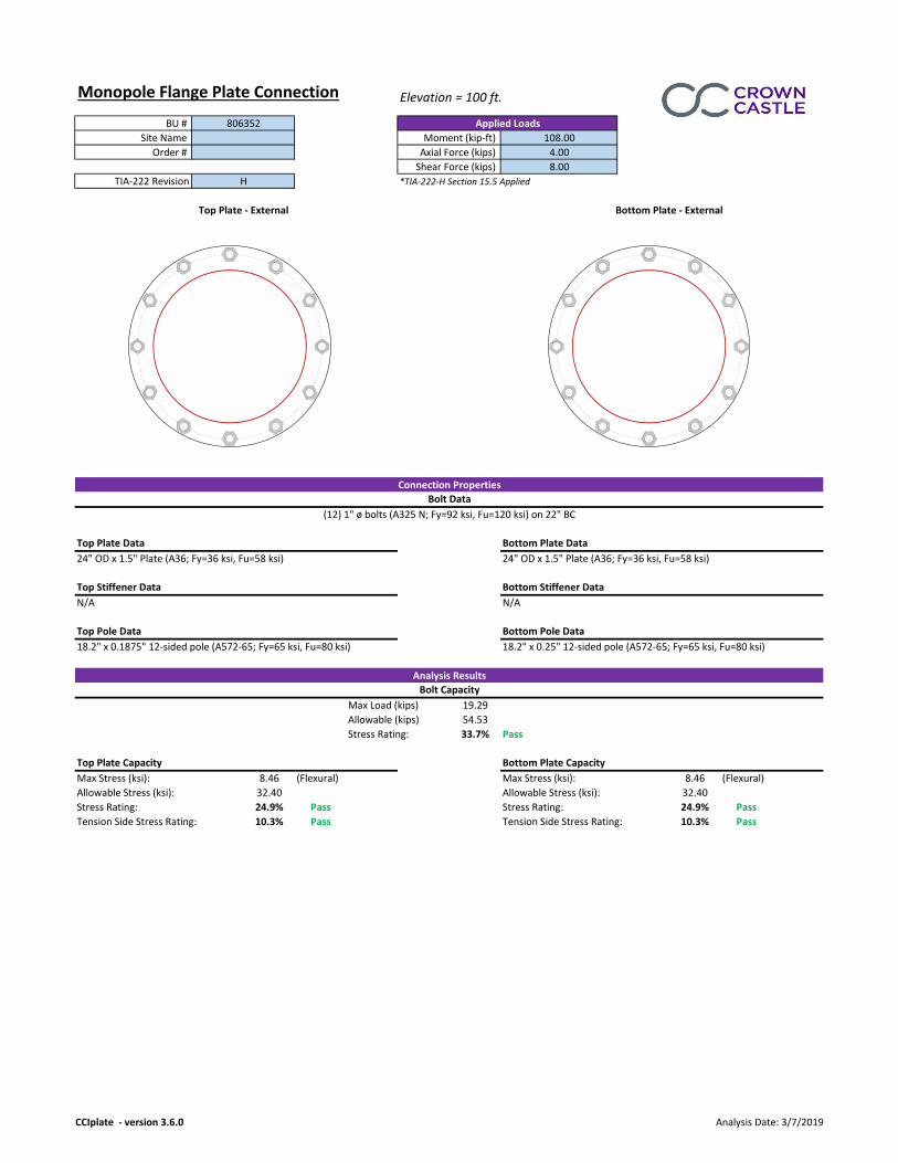
Monopole Flange Plate Connection
*TIA-222-H Section 15.5 Applied
Top Plate Data Bottom Plate Data
24" OD x 1.5" Plate (A36; Fy=36 ksi, Fu=58 ksi) 24" OD x 1.5" Plate (A36; Fy=36 ksi, Fu=58 ksi)
Top Stiffener Data Bottom Stiffener Data
N/A N/A
Top Pole Data Bottom Pole Data
18.2" x 0.1875" 12-sided pole (A572-65; Fy=65 ksi, Fu=80 ksi) 18.2" x 0.25" 12-sided pole (A572-65; Fy=65 ksi, Fu=80 ksi)
Max Load (kips) 19.29
Allowable (kips) 54.53
Stress Rating: 33.7% Pass
Top Plate Capacity Bottom Plate Capacity
8.46 (Flexural) 8.46 (Flexural)
32.40 32.40
24.9% Pass 24.9% Pass
10.3% Pass 10.3% Pass
Elevation = 100 ft.
Order # Axial Force (kips) 4.00
BU # 806352 Applied Loads
Site Name Moment (kip-ft) 108.00
Shear Force (kips) 8.00
TIA-222 Revision H
Bottom Plate - ExternalTop Plate - External
Allowable Stress (ksi): Allowable Stress (ksi):
Connection Properties
Bolt Data
Analysis Results
Bolt Capacity
Max Stress (ksi): Max Stress (ksi):
(12) 1" ø bolts (A325 N; Fy=92 ksi, Fu=120 ksi) on 22" BC
Stress Rating: Stress Rating:
Tension Side Stress Rating: Tension Side Stress Rating:
Show image?
Plate Dia.
Shaft Dia.
Pole Shape
Plate Type:
Plate Geometry:
Plate Quantity
Plate Dia. 2
Shaft Dia. 2
CCIplate - version 3.6.0 Analysis Date: 3/7/2019
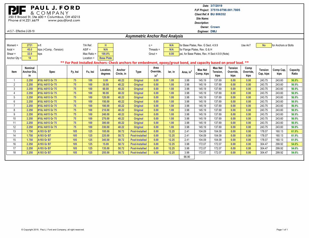
Date:
PJF Project:
Client Ref. #
Site Name:
Description:
Owner:
v4.5.7 - Effective 2-28-19 Engineer:
Moment = 2721 k-ft TIA Ref. H η = N/A for Base Plates, Rev. G Sect. 4.9.9 Use An? No for Anchors or Bolts
Axial = 45.0 kips (+Comp, -Tension) ASIF = N/A Threads = N/A for Flange Plates, Rev. G & H
Shear = 32.0 kips Max Ratio = 100.0% Grout = 0.00 psi, for Base Plates, Rev. H Sect 4.9.9 (Note)
Anchor Qty = 18 Location = Base Plate
Item
Nominal
Anchor Dia,
in
Spec Fy, ksi Fu, ksiLocation,
degrees
Anchor
Circle, inType
Area
Override,
in2
lar, in Area, in2 Max Net
Comp, kips
Max Net
Tension,
kips
Tension
Override,
kips
Comp
Override,
kips
Tension
Cap, kips
Comp Cap,
kips
Capacity
Ratio
1 2.250 #18J A615 Gr 75 75 100 0.00 48.22 Original 0.00 1.00 3.98 145.19 137.69 0.00 0.00 243.75 243.60 56.9%
2 2.250 #18J A615 Gr 75 75 100 30.00 48.22 Original 0.00 1.00 3.98 145.19 137.69 0.00 0.00 243.75 243.60 56.9%
3 2.250 #18J A615 Gr 75 75 100 60.00 48.22 Original 0.00 1.00 3.98 145.19 137.69 0.00 0.00 243.75 243.60 56.9%
4 2.250 #18J A615 Gr 75 75 100 90.00 48.22 Original 0.00 1.00 3.98 145.19 137.69 0.00 0.00 243.75 243.60 56.9%
5 2.250 #18J A615 Gr 75 75 100 120.00 48.22 Original 0.00 1.00 3.98 145.19 137.69 0.00 0.00 243.75 243.60 56.9%
6 2.250 #18J A615 Gr 75 75 100 150.00 48.22 Original 0.00 1.00 3.98 145.19 137.69 0.00 0.00 243.75 243.60 56.9%
7 2.250 #18J A615 Gr 75 75 100 180.00 48.22 Original 0.00 1.00 3.98 145.19 137.69 0.00 0.00 243.75 243.60 56.9%
8 2.250 #18J A615 Gr 75 75 100 210.00 48.22 Original 0.00 1.00 3.98 145.19 137.69 0.00 0.00 243.75 243.60 56.9%
9 2.250 #18J A615 Gr 75 75 100 240.00 48.22 Original 0.00 1.00 3.98 145.19 137.69 0.00 0.00 243.75 243.60 56.9%
10 2.250 #18J A615 Gr 75 75 100 270.00 48.22 Original 0.00 1.00 3.98 145.19 137.69 0.00 0.00 243.75 243.60 56.9%
11 2.250 #18J A615 Gr 75 75 100 300.00 48.22 Original 0.00 1.00 3.98 145.19 137.69 0.00 0.00 243.75 243.60 56.9%
12 2.250 #18J A615 Gr 75 75 100 330.00 48.22 Original 0.00 1.00 3.98 145.19 137.69 0.00 0.00 243.75 243.60 56.9%
13 1.750 A193 Gr B7 105 125 105.00 58.72 Post-Installed 0.00 12.25 2.41 104.09 104.09 0.00 0.00 178.07 160.13 61.9%
14 1.750 A193 Gr B7 105 125 225.00 58.72 Post-Installed 0.00 12.25 2.41 104.09 104.09 0.00 0.00 178.07 160.13 61.9%
15 1.750 A193 Gr B7 105 125 345.00 58.72 Post-Installed 0.00 12.25 2.41 104.09 104.09 0.00 0.00 178.07 160.13 61.9%
16 2.250 A193 Gr B7 105 125 15.00 58.72 Post-Installed 0.00 12.25 3.98 172.07 172.07 0.00 0.00 304.47 299.92 54.6%
17 2.250 A193 Gr B7 105 125 135.00 58.72 Post-Installed 0.00 12.25 3.98 172.07 172.07 0.00 0.00 304.47 299.92 54.6%
18 2.250 A193 Gr B7 105 125 255.00 58.72 Post-Installed 0.00 12.25 3.98 172.07 172.07 0.00 0.00 304.47 299.92 54.6%
66.90
3/7/2019
37519-0798.001.7805
BU 806352
Crown
Asymmetric Anchor Rod Analysis
DMJ
** For Post Installed Anchors: Check anchors for embedment, epoxy/grout bond, and capacity based on proof load. **
© Copyright 2019, Paul J. Ford and Company, all right reserved. Page 1 of 1

Monopole Base Plate Connection
*TIA-222-H Section 15.5 Applied
#VALUE!
Anchor Rod Data Anchor Rod Summary (units of kips, kip-in)
(12) 2-1/4" ø bolts (A615-75 N; Fy=75 ksi, Fu=100 ksi) on 48.22" BC Pu_c = 145.06 φPn_c = 243.75 Stress Rating
Vu = 2.67 φVn = 73.13 56.8%
Base Plate Data Mu = n/a φMn = n/a Pass
54.22" OD x 2.5" Plate (A572-60; Fy=60 ksi, Fu=75 ksi)
Base Plate Summary
Stiffener Data Max Stress (ksi): 21.28 (Flexural)
N/A Allowable Stress (ksi): 54
Stress Rating: 37.5% Pass
Pole Data
40.3" x 0.34375" 12-sided pole (A572-65; Fy=65 ksi, Fu=80 ksi)
45.00
32.00
Adjusted Pole Reactions
BU # 806352
Applied Loads
Site Name
Order #
Analysis Considerations
Site Info
TIA-222 Revision H
Grout Considered: No
Analysis ResultsConnection Properties
Iar (in) 1
Moment (kip-ft) 1705.00
Axial Force (kips) 45.00
Shear Force (kips) 32.00
Moment (kip-ft)
Axial Force (kips)
Shear Force (kips)
0.00
CCIplate - version 3.6.0 Analysis Date: 3/7/2019
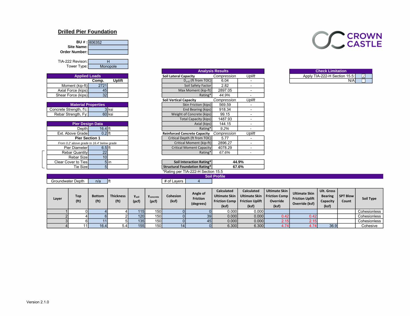
TIA-222 Revison: Check Pier Capacity only at location of Max Moment? No
Tower Type:
Soil Lateral Capacity Compression UpliftComp. Uplift 6.04 -
2721 2.82 -
45 2897.05 -
32 44.9% -
Soil Vertical Capacity Compression Uplift
569.59 -
3 ksi 918.34 -
60 ksi 99.15 -
1487.93 -
144.15 -
16.4 ft 9.2% -
0.2 ft Reinforced Concrete Capacity Compression Uplift
5.77 -
2896.27 -
6.5 ft 4078.29 -
22 67.6% -
10
5 in
5
*Rating per TIA-222-H Section 15.5
n/a ft # of Layers 4
FALSE 1 0 4 4 115 150 0 0 0.000 0.000
FALSE 2 4 6 2 120 150 0 39 0.000 0.000 0.42 0.42
FALSE 3 6 11 5 135 150 0 45 0.000 0.000 2.15 2.15
FALSE 4 11 16.4 5.4 155 150 14 0 6.300 6.300 4.74 4.74 36.9
Check Limitation
Apply TIA-222-H Section 15.5:
Pier Diameter
Rebar Quantity
Rebar Strength, Fy:
End Bearing (kips)
Total Capacity (kips)Axial (kips)
Depth
Ext. Above Grade
Critical Depth (ft from TOC)Critical Moment (kip-ft)
Critical Moment CapacityRating*
Pier Section 1
From 0.2' above grade to 16.4' below grade
Rebar Size
Clear Cover to Ties
Tie Size
Rating*
Ultimate Skin
Friction Uplift
Override (ksf)
Groundwater Depth
Soil Profile
Soil TypeSPT Blow
Count
Ult. Gross
Bearing
Capacity
(ksf)
γsoil
(pcf)
γconcrete
(pcf)
Cohesion
(ksf)
Angle of
Friction
(degrees)
Calculated
Ultimate Skin
Friction Uplift
(ksf)
Calculated
Ultimate Skin
Friction Comp
(ksf)
LayerTop
(ft)
Bottom
(ft)
Thickness
(ft)
Ultimate Skin
Friction Comp
Override
(ksf)
Analysis Results
Drilled Pier Foundation
BU # :
Site Name:
Order Number:
Monopole
Applied Loads
Material Properties
Pier Design Data
H
806352
Moment (kip-ft)
Axial Force (kips)
Shear Force (kips)
Concrete Strength, f'c:
Dv=0 (ft from TOC)
Soil Safety FactorMax Moment (kip-ft)
Rating*
Skin Friction (kips)
Weight of Concrete (kips)
Cohesive
44.9%
67.6%
Soil Interaction Rating*Structural Foundation Rating*
N/A
Cohesionless
Cohesionless
Cohesionless
Version 2.1.0
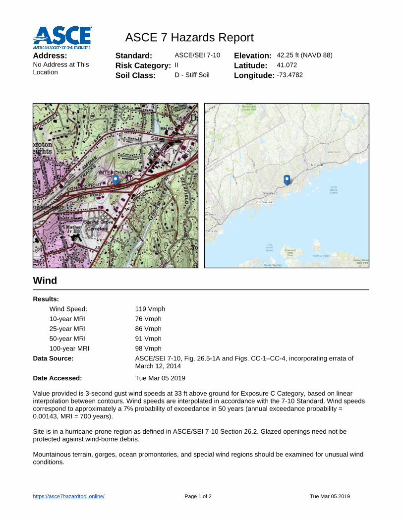
ASCE 7 Hazards ReportAddress:No Address at This Location
Standard: ASCE/SEI 7-10
Risk Category: II
Soil Class: D - Stiff Soil
Elevation: 42.25 ft (NAVD 88)
Latitude:Longitude:
41.072
-73.4782
Wind
Results:
Data Source:
Date Accessed:
Wind Speed: 119 Vmph
10-year MRI 76 Vmph
25-year MRI 86 Vmph
50-year MRI 91 Vmph
100-year MRI 98 Vmph
ASCE/SEI 7-10, Fig. 26.5-1A and Figs. CC-1–CC-4, incorporating errata of March 12, 2014
Tue Mar 05 2019
Value provided is 3-second gust wind speeds at 33 ft above ground for Exposure C Category, based on linear interpolation between contours. Wind speeds are interpolated in accordance with the 7-10 Standard. Wind speeds correspond to approximately a 7% probability of exceedance in 50 years (annual exceedance probability = 0.00143, MRI = 700 years).
Site is in a hurricane-prone region as defined in ASCE/SEI 7-10 Section 26.2. Glazed openings need not be protected against wind-borne debris.
Mountainous terrain, gorges, ocean promontories, and special wind regions should be examined for unusual wind conditions.
Page 1 of 2https://asce7hazardtool.online/ Tue Mar 05 2019

Ice
Results:
Data Source:
Date Accessed:
Ice Thickness: 0.75 in.
Concurrent Temperature: 15 F
Gust Speed: 50 mph
Standard ASCE/SEI 7-10, Figs. 10-2 through 10-8
Tue Mar 05 2019
Ice thicknesses on structures in exposed locations at elevations higher than the surrounding terrain and in valleys and gorges may exceed the mapped values.
Values provided are equivalent radial ice thicknesses due to freezing rain with concurrent 3-second gust speeds, for a 50-year mean recurrence interval, and temperatures concurrent with ice thicknesses due to freezing rain. Thicknesses for ice accretions caused by other sources shall be obtained from local meteorological studies. Ice thicknesses in exposed locations at elevations higher than the surrounding terrain and in valleys and gorges may exceed the mapped values.
The ASCE 7 Hazard Tool is provided for your convenience, for informational purposes only, and is provided “as is” and without warranties of any kind. The location data included herein has been obtained from information developed, produced, and maintained by third party providers; or has been extrapolated from maps incorporated in the ASCE 7 standard. While ASCE has made every effort to use data obtained from reliable sources or methodologies, ASCE does not make any representations or warranties as to the accuracy, completeness, reliability, currency, or quality of any data provided herein. Any third-party links provided by this Tool should not be construed as an endorsement, affiliation, relationship, or sponsorship of such third-party content by or from ASCE.
ASCE does not intend, nor should anyone interpret, the results provided by this Tool to replace the sound judgment of a competent professional, having knowledge and experience in the appropriate field(s) of practice, nor to substitute for the standard of care required of such professionals in interpreting and applying the contents of this Tool or the ASCE 7 standard.
In using this Tool, you expressly assume all risks associated with your use. Under no circumstances shall ASCE or its officers, directors, employees, members, affiliates, or agents be liable to you or any other person for any direct, indirect, special, incidental, or consequential damages arising from or related to your use of, or reliance on, the Tool or any information obtained therein. To the fullest extent permitted by law, you agree to release and hold harmless ASCE from any and all liability of any nature arising out of or resulting from any use of data provided by the ASCE 7 Hazard Tool.
Page 2 of 2https://asce7hazardtool.online/ Tue Mar 05 2019

T-11
RE
V.
DATE
CH
K'D
BY
DR
AW
N B
Y
PR
OF
ES
SIO
NA
L E
NG
INE
ER
SE
AL
DE
SC
RIP
TIO
N
DATE:
SCALE:
JOB NO.
Sheet No. of
09/06/18AS NOTED
18000.66
8
engi
neer
ing
Cent
ered
on
Solut
ions
SM
ww
w.C
ente
kEng
.com
(203
) 488
-058
0(2
03) 4
88-8
587
Fax
63-2
Nor
th B
ranf
ord
Road
Bran
ford
, CT 0
6405
WIR
EL
ES
S C
OM
MU
NIC
AT
ION
S F
AC
ILIT
Y
AT
&T
MO
BIL
ITY
0
09/0
6/1
8KA
WTJ
RC
ON
ST
RU
CT
ION
DR
AW
ING
S -
IS
SU
ED
FO
R C
ON
ST
RU
CT
ION
1
03/2
7/1
9FJ
PTJ
RC
ON
ST
RU
CT
ION
DR
AW
ING
S -
IS
SU
ED
FO
R C
ON
ST
RU
CT
ION
TITLE SHEET
CT2104 - LTE 5C AWS/6C 700 UPPER D/5G 850DARIEN
CROWN CASTLE SITE NO.: 80635250 LEDGE ROAD
DARIEN, CT 06820
WIRELESS COMMUNICATIONS FACILITY
AT&T SITE NUMBER:
SITE ADDRESS:
LESSEE/APPLICANT:
ENGINEER:
PROJECT COORDINATES:
{CROWN CASTLE SITE NO.: 80635250 LEDGE ROADDARIEN, CT 06820}
PROJECTLOCATION
01,000 1,000 2,000500
{\C1;CT2104}
CENTEK ENGINEERING, INC.63-2 NORTH BRANFORD RD. BRANFORD,CT 06405
AT&T MOBILITY500 ENTERPRISE DRIVE, SUITE 3AROCKY HILL, CT 06067
AT&T SITE NAME:
{\C1;DARIEN}
19.
18.
9.
1.
8.
7.
6.
5.
4.
3.
17.
16.
15.
14.
13.
12.
11.
10.
20.
21.
CONTRACTOR SHALL REVIEW ALL DRAWINGS AND SPECIFICATIONS IN THE CONTRACT DOCUMENT SET. CONTRACTOR SHALL COORDINATE ALL WORK SHOWN IN THE SET OF DRAWINGS. THE CONTRACTOR SHALL PROVIDE A COMPLETE SET OF DRAWINGS TO ALL SUBCONTRACTORS AND ALL RELATED PARTIES. THE SUBCONTRACTORS SHALL EXAMINE ALL THE DRAWINGS AND SPECIFICATIONS FOR THE INFORMATION THAT AFFECTS THEIR WORK.CONTRACTOR SHALL PROVIDE A COMPLETE BUILD-OUT WITH ALL FINISHES, STRUCTURAL, MECHANICAL, AND ELECTRICAL COMPONENTS AND PROVIDE ALL ITEMS AS SHOWN OR INDICATED ON THE DRAWINGS OR IN THE WRITTEN SPECIFICATIONS.CONTRACTOR SHALL FURNISH ALL MATERIAL, LABOR AND EQUIPMENT TO COMPLETE THE WORK AND FURNISH A COMPLETED JOB ALL IN ACCORDANCE WITH LOCAL AND STATE GOVERNING AUTHORITIES AND OTHER AUTHORITIES HAVING LAWFUL JURISDICTION OVER THE WORK.CONTRACTOR SHALL SECURE AND PAY FOR ALL PERMITS AND ALL INSPECTIONS REQUIRED AND SHALL ALSO PAY FEES REQUIRED FOR THE GENERAL CONSTRUCTION, PLUMBING, ELECTRICAL AND HVAC. PERMITS SHALL BE PAID FOR BY THE RESPECTIVE SUBCONTRACTORS.
CONTRACTOR SHALL MAINTAIN A CURRENT SET OF DRAWINGS AND SPECIFICATIONS ON SITE AT ALL TIMES AND INSURE DISTRIBUTION OF NEW DRAWINGS TO SUBCONTRACTORS AND OTHER RELEVANT PARTIES AS SOON AS THEY ARE MADE AVAILABLE. ALL OLD DRAWINGS SHALL BE MARKED VOID AND REMOVED FROM THE CONTRACT AREA. THE CONTRACTOR SHALL FURNISH AN 'AS-BUILT' SET OF DRAWINGS TO OWNER UPON COMPLETION OF PROJECT.LOCATION OF EQUIPMENT, AND WORK SUPPLIED BY OTHERS THAT IS DIAGRAMMATICALLY INDICATED ON THE DRAWINGS SHALL BE DETERMINED BY THE CONTRACTOR. THE CONTRACTOR SHALL DETERMINE LOCATIONS AND DIMENSIONS SUBJECT TO STRUCTURAL CONDITIONS AND WORK OF THE SUBCONTRACTORS.THE CONTRACTOR IS SOLELY RESPONSIBLE TO DETERMINE CONSTRUCTION PROCEDURE AND SEQUENCE, AND TO ENSURE THE SAFETY OF THE EXISTING STRUCTURES AND ITS COMPONENT PARTS DURING CONSTRUCTION. THIS INCLUDES THE ADDITION OF WHATEVER SHORING, BRACING, UNDERPINNING, ETC. THAT MAY BE NECESSARY. MAINTAIN EXISTING BUILDING'S/PROPERTY'S OPERATIONS, COORDINATE WORK WITH BUILDING/PROPERTY OWNER.
DRAWINGS INDICATE THE MINIMUM STANDARDS, BUT IF ANY WORK SHOULD BE INDICATED TO BE SUBSTANDARD TO ANY ORDINANCES, LAWS, CODES, RULES, OR REGULATIONS BEARING ON THE WORK, THE CONTRACTOR SHALL INCLUDE IN HIS WORK AND SHALL EXECUTE THE WORK CORRECTLY IN ACCORDANCE WITH SUCH ORDINANCES, LAWS, CODES, RULES OR REGULATIONS WITH NO INCREASE IN COSTS.ALL UTILITY WORK SHALL BE IN ACCORDANCE WITH LOCAL UTILITY COMPANY REQUIREMENTS AND SPECIFICATIONS.
ALL EQUIPMENT AND PRODUCTS PURCHASED ARE TO BE REVIEWED BY CONTRACTOR AND ALL APPLICABLE SUBCONTRACTORS FOR ANY CONDITION PER MFR.'S RECOMMENDATIONS. CONTRACTOR TO SUPPLY THESE ITEMS AT NO COST TO OWNER OR CONSTRUCTION MANAGER.
CONTRACTOR SHALL BE RESPONSIBLE FOR ALL ON-SITE SAFETY FROM THE TIME THE JOB IS AWARDED UNTIL ALL WORK IS COMPLETE AND ACCEPTED BY THE OWNER.
CONTRACTOR TO REVIEW ALL SHOP DRAWINGS AND SUBMIT COPY TO ENGINEER FOR APPROVAL. DRAWINGS MUST BEAR THE CHECKER'S INITIALS BEFORE SUBMITTING TO THE CONSTRUCTION MANAGER FOR REVIEW.THE CONTRACTOR SHALL FIELD VERIFY ALL DIMENSIONS, ELEVATIONS, ANGLES, AND EXISTING CONDITIONS AT THE SITE, PRIOR TO FABRICATION AND/OR INSTALLATION OF ANY WORK IN THE CONTRACT AREA.COORDINATION, LAYOUT, FURNISHING AND INSTALLATION OF CONDUIT AND ALL APPURTENANCES REQUIRED FOR PROPER INSTALLATION OF ELECTRICAL AND TELECOMMUNICATION SERVICE SHALL BE THE SOLE RESPONSIBILITY OF THE CONTRACTOR.ALL EQUIPMENT AND PRODUCTS PURCHASED ARE TO BE REVIEWED BY CONTRACTOR AND ALL APPLICABLE SUB- CONTRACTORS FOR ANY CONDITION PER THE MANUFACTURER'S RECOMMENDATIONS. CONTRACTOR TO SUPPLY THESE ITEMS AT NO COST TO OWNER OR CONSTRUCTION MANAGER.ALL DAMAGE CAUSED TO ANY EXISTING STRUCTURE SHALL BE THE SOLE RESPONSIBILITY OF THE CONTRACTOR. THE CONTRACTOR WILL BE HELD LIABLE FOR ALL REPAIRS REQUIRED FOR EXISTING STRUCTURES IF DAMAGED DURING CONSTRUCTION ACTIVITIES.THE CONTRACTOR SHALL CONTACT "CALL BEFORE YOU DIG" AT LEAST 48 HOURS PRIOR TO ANY EXCAVATIONS AT 1-800-922-4455. ALL UTILITIES SHALL BE IDENTIFIED AND CLEARLY MARKED PRIOR TO ANY EXCAVATION WORK. CONTRACTOR SHALL MAINTAIN AND PROTECT MARKED UTILITIES THROUGHOUT PROJECT COMPLETION.CONTRACTOR SHALL COMPLY WITH OWNERS ENVIRONMENTAL ENGINEER ON ALL METHODS AND PROVISIONS FOR ALL EXCAVATION ACTIVITIES INCLUDING SOIL DISPOSAL. ALL BACKFILL MATERIALS TO BE PROVIDED BY THE CONTRACTOR.
THE COMPOUND, TOWER, PRIMARY GROUND RING, ELECTRICAL SERVICE TO THE METER BANK AND TELEPHONE SERVICE TO THE DEMARCATION POINT ARE PROVIDED BY SITE OWNER. AS BUILT FIELD CONDITIONS REGARDING THESE ITEMS SHALL BE CONFIRMED BY THE CONTRACTOR. SHOULD ANY FIELD CONDITIONS PRECLUDE COMPLIANCE WITH THE DRAWINGS, THE CONTRACTOR SHALL IMMEDIATELY NOTIFY THE ENGINEER AND SHALL NOT PROCEED WITH ANY AFFECTED WORK.2.
ALL WORK SHALL BE IN ACCORDANCE WITH THE 2015 INTERNATIONAL BUILDING CODE AS MODIFIED BY THE 2018 CONNECTICUT STATE BUILDING CODE, INCLUDING THE TIA-222 REVISION "G" STRUCTURAL STANDARDS FOR STEEL ANTENNA TOWERS AND SUPPORTING STRUCTURES, 2018 CONNECTICUT FIRE SAFETY CODE AND, 2017 NATIONAL ELECTRICAL CODE AND LOCAL CODES.500 ENTERPRISE DRIVEROCKY HILL, CONNECTICUT
{50 LEDGE ROADDARIEN, CONNECTICUT}
1. HEAD NORTHEAST ON ENTERPRISE DR TOWARD CAPITAL BLVD 0.36 MI2. TURN LEFT ONTO CAPITAL BLVD 0.27 MI3. TURN LEFT ONTO WEST ST 0.30 MI4. TURN LEFT TO MERGE ONTO I-91 S TOWARD NEW HAVEN 9.59 MI5. TAKE EXIT 17 FOR CT-15 S/W CROSS PKWY TOWARD E MAIN ST 30.24 MI6. MERGE ONTO CT-8 S TOWARD BRIDGEPORT 5.93 MI7. MERGE ONTO I-95 S/GOVERNOR JOHN DAVIS LODGE TPKE TOWARD NY CITY 17.23 MI8. TAKE EXIT 11 FOR US-1 TOWARD DARIEN/ROWAYTON 0.18 MI9. KEEP LEFT TO TAKE RAMP TOWARD NOROTON 0.05 MI10. MERGE ONTO LEDGE RD 0.24 MI11. 126 LEDGE RD IS ON THE RIGHT
FROM:
SITE DIRECTIONS
TO:
GENERAL NOTES
VICINITY MAP SCALE: 1" = 1000'
PROJECT INFORMATION
SITE COORDINATES AND GROUND ELEVATION REFERENCED FROM GOOGLE EARTH.
PROJECT SUMMARY
∂∂∂
∂∂∂∂∂∂
AT&T PACE ID NUMBER: PACE JOB 1 - MRCTB030972PACE JOB 2 - MRCTB031059PACE JOB 3 - MRCTB032125
AT&T FA LOCATION CODE: 10035058
SHEET INDEX
T-1 TITLE SHEET 0
C-1 PLANS AND ELEVATION 0
E-1 SCHEMATIC DIAGRAM AND NOTES 0
C-2 ANTENNA CONFIGURATION DETAILS 0
E-2 WIRING DIAGRAM 0
E-3 TYPICAL ELECTRICAL DETAILS 0
N-1 NOTES, SPECIFICATIONS AND ANTENNA SCHEDULE 0
C-3 DETAILS 0

N-1
RE
V.
DATE
CH
K'D
BY
DR
AW
N B
Y
PR
OF
ES
SIO
NA
L E
NG
INE
ER
SE
AL
DE
SC
RIP
TIO
N
DATE:
SCALE:
JOB NO.
Sheet No. of
09/06/18AS NOTED
18000.66
8
engi
neer
ing
Cent
ered
on
Solut
ions
SM
ww
w.C
ente
kEng
.com
(203
) 488
-058
0(2
03) 4
88-8
587
Fax
63-2
Nor
th B
ranf
ord
Road
Bran
ford
, CT 0
6405
WIR
EL
ES
S C
OM
MU
NIC
AT
ION
S F
AC
ILIT
Y
AT
&T
MO
BIL
ITY
0
09/0
6/1
8KA
WTJ
RC
ON
ST
RU
CT
ION
DR
AW
ING
S -
IS
SU
ED
FO
R C
ON
ST
RU
CT
ION
1
03/2
7/1
9FJ
PTJ
RC
ON
ST
RU
CT
ION
DR
AW
ING
S -
IS
SU
ED
FO
R C
ON
ST
RU
CT
ION
NOTES,SPECIFICATIONS
AND ANTENNASCHEDULE
2
∂
∂
∂
∂
ANTENNA SCHEDULE
SECTOR AZIMUTHANTENNA
ANTE
NN
A
HEI
GH
TBANDEXISTING/PROPOSED
A1
A4
B1
B4
C1
C4
EXISTING
TMA/DIPLEXER/TRIPLEXER (QTY) (E/P) RRU (QTY) FEEDER (QTY)
\pxi-3,l4,t4;TPX-070821 (4)
SIZE(INCHES)(L x W x D)
72 x 12 x 9.6 TRIPLEXER:
DIPLEXER:
(E/P) RAYCAP (QTY)
\A1;\pxi-3.0476,l4.0476,t4.0476;(E) RAYCAP DC6-48-60-18-8F (1)
EXISTING
LTE 700/850/1900/1900/5G 850/AWS
UMTS 850
LTE 700/WCS CCI: OPA-65R-LCUU-H6
QUINTEL: QS66512-2 89' 75°
75°
\pxi-3,l4,t4; POWERWAVE: LGP 21901 (2)
(E) RRUS-11 (1), (E) RRUS-32 (1) \A1;1{\H0.7x;\S1/4;\H1.4286x;"\H1x;%%C ANDREW COAX (2)}SIZE (INCHES)(L x W x D)RRU
RRUS-32 27.2 x 12.1 x 7
RRUS-32 B2
RRUS-11 19.7 x 17 x 7.2
A3
B3
C3
POWERWAVE: 7770
EXISTING 72 x 14.8 x 7.4
55 x 11 x 5 142°
FEEDER AND DC POWER (1)
96 x 14.4 x 8.6 315°
92.7 x 14.4 x 7 315°
22°
27.2 x 12.1 x 7
4426 B66 15.0 x 13.2 x 5.8
4478 B5 16.5 x 13.4 x 7.7
B14 4478 14.9 x 13.1 x 7.3TMA: \pxi-3,l4,t4; POWERWAVE: LGP 21401 850 BYPASS (2)
(E) RRUS-32 B2 (1), (P) B14 4478 (1), (P) 4478 B5 (1), (P) 4426 B66 (1) \A1;1{\H0.7x;\S5/8;\H1.4286x;%%C COAX (3), \A0;\H0.99998x;FEEDER AND DC POWER (1)}
EXISTING \pxi-3,l4,t4;TPX-070821 (4)72 x 12 x 9.6 TRIPLEXER:
DIPLEXER:EXISTING
LTE 700/850/1900/1900/5G 850/AWS
UMTS 850
LTE 700/WCS CCI: OPA-65R-LCUU-H6
QUINTEL: QS66512-2 195°
195°
\pxi-3,l4,t4; POWERWAVE: LGP 21901 (2)
(E) RRUS-11 (1), (E) RRUS-32 (1)\A1;1{\H0.7x;\S1/4;\H1.4286x;"\H1x;%%C ANDREW COAX (2)}POWERWAVE: 7770
EXISTING 72 x 14.8 x 7.4
55 x 11 x 5 262° FEEDER AND DC POWER (1)TMA: \pxi-3,l4,t4; POWERWAVE: LGP 21401 850 BYPASS (2)
(E) RRUS-32 B2 (1), (P) B14 4478 (1), (P) 4478 B5 (1), (P) 4426 B66 (1)
EXISTING
EXISTING
EXISTING
LTE 700/850/1900/1900/5G 850/AWS
UMTS 850LTE 700/WCS CCI: OPA-65R-LCUU-H8
CCI: TPA-65R-LCUUUU-H8
POWERWAVE: 7770 55 x 11 x 5
\pxi-3,l4,t4;TPX-070821 (4)
\pxi-3,l4,t4; POWERWAVE: LGP 21901 (2) TMA: \pxi-3,l4,t4; POWERWAVE: LGP 21401 850 BYPASS (2)DIPLEXER:
(E) RRUS-11 (1), (E) RRUS-32 (1)
(E) RRUS-32 B2 (1), (P) 4478 B5 (1), (P) 4426 B66 (1)
\A1;1{\H0.7x;\S1/4;\H1.4286x;"\H1x;%%C ANDREW COAX (2)}FEEDER AND DC POWER (1)
\A1;1{\H0.7x;\S5/8;\H1.4286x;%%C COAX (3), \A0;\H0.99998x;FEEDER AND DC POWER (1)}
\A1;1{\H0.7x;\S1/4;\H1.4286x;"\H1x;%%C ANDREW COAX (2)}FEEDER AND DC POWER (1)
\A1;1{\H0.7x;\S5/8;\H1.4286x;%%C COAX (3), \A0;\H0.99998x;FEEDER AND DC POWER (1)}
89'
89'
89'
89'
89'
89'
89'
89'
\A1;\pxi-3.0476,l4.0476,t4.0476;(E) RAYCAP DC6-48-60-18-8F (1)
TRIPLEXER:

\A1;13'-10"%%P
\A1;1
3'-9"%
%P
RE
V.
DATE
CH
K'D
BY
DR
AW
N B
Y
PR
OF
ES
SIO
NA
L E
NG
INE
ER
SE
AL
DE
SC
RIP
TIO
N
DATE:
SCALE:
JOB NO.
Sheet No. of
09/06/18AS NOTED
18000.66
8
engi
neer
ing
Cent
ered
on
Solut
ions
SM
ww
w.C
ente
kEng
.com
(203
) 488
-058
0(2
03) 4
88-8
587
Fax
63-2
Nor
th B
ranf
ord
Road
Bran
ford
, CT 0
6405
WIR
EL
ES
S C
OM
MU
NIC
AT
ION
S F
AC
ILIT
Y
AT
&T
MO
BIL
ITY
0
09/0
6/1
8KA
WTJ
RC
ON
ST
RU
CT
ION
DR
AW
ING
S -
IS
SU
ED
FO
R C
ON
ST
RU
CT
ION
1
03/2
7/1
9FJ
PTJ
RC
ON
ST
RU
CT
ION
DR
AW
ING
S -
IS
SU
ED
FO
R C
ON
ST
RU
CT
ION
PLANS ANDELEVATION
C-1
1SCALE: 1/4" = 1'-0"
3
TOP OF EXISTING MONOPOLEEL. %%P117'{ }A.G.L.
C-1
3SCALE: 1/8" = 1'-0"
GRADE
TRUE NORTH
0GRAPHIC SCALE
( IN FEET )1 inch = ft.
0( IN FEET )
1 inch = ft.
C-1
3
EXISTING COMPOUND CHAINLINK FENCE
C-1
2
EXISTING DOUBLE ACCESS GATE
EXISTING AT&T GENERATOR ON CONCRETE PAD
EXISTING METER BANK
EXISTING ICE BRIDGE
EXISTING %%P117' TALL MONOPOLE TOWEREXISTING AT&T EQUIPMENT SHELTER
EXISTING EQUIPMENT ROOM, BY OTHERS. AT&T ANTENNASEL. %%P89'{ }A.G.L.
EXISTING AT&T CABLES ROUTED INSIDE MONOPOLE.
EXISTING %%P117' TALL MONOPOLE
EXISTING AT&T EQUIPMENT ROOM
EXISTING AT&T GPS ANTENNAS, TYP. OF (2)
C-1
2SCALE: 1/2" = 1'-0" TRUE NORTH
EXISTING TRANSFER SWITCH
EXISTING AC PANEL
EXISTING EQUIPMENT SHELTER ACCESS DOOR
EXISTING TELCO BACKBOARD
EXISTING DESK
EXISTING RBS CABINET
EXISTING FIF RACK
EXISTING DC POWER PLANT
EXISTING FLOOR MOUNTED BATTERY RACK
∂∂
EXISTING GALAXY CABINET
EXISTING HVAC UNITS, TYP OF (2)
∂∂
EXISTING AT&T COAX CABLE PORTS
PROPOSED AT&T SURGE ARRESTORS(P/N: POLYPHASER TSXDC-4310FM)TYP. OF (4) PER RRU/(8) TOTALCONNECTED TO (P) {B14 4478}

RE
V.
DATE
CH
K'D
BY
DR
AW
N B
Y
PR
OF
ES
SIO
NA
L E
NG
INE
ER
SE
AL
DE
SC
RIP
TIO
N
DATE:
SCALE:
JOB NO.
Sheet No. of
09/06/18AS NOTED
18000.66
8
engi
neer
ing
Cent
ered
on
Solut
ions
SM
ww
w.C
ente
kEng
.com
(203
) 488
-058
0(2
03) 4
88-8
587
Fax
63-2
Nor
th B
ranf
ord
Road
Bran
ford
, CT 0
6405
WIR
EL
ES
S C
OM
MU
NIC
AT
ION
S F
AC
ILIT
Y
AT
&T
MO
BIL
ITY
0
09/0
6/1
8KA
WTJ
RC
ON
ST
RU
CT
ION
DR
AW
ING
S -
IS
SU
ED
FO
R C
ON
ST
RU
CT
ION
1
03/2
7/1
9FJ
PTJ
RC
ON
ST
RU
CT
ION
DR
AW
ING
S -
IS
SU
ED
FO
R C
ON
ST
RU
CT
ION
ANTENNACONFIGURATION
DETAILS
4
C-2
3SCALE: 1/2" = 1'-0"
EXISTING ANTENNA ELEVATION
EXISTING RRUS-11'S, TYP. OF (1) PERSECTOR/(3) TOTAL
EXISTING AT&T PANEL ANTENNA POS. 1,(ALPHA & BETA SECTOR)(P/N: QUINTEL QS66512-2)TYP. OF (1) PER SECTOR/(2) TOTAL{TO REMAIN}
EXISTING TMA'S, TYP. OF (2)PER SECTOR/(6) TOTAL {TO REMAIN}
EXISTING AT&T PANEL ANTENNA POS. 4,(P/N: POWERWAVE 7770),TYP. OF (1) PER SECTOR/(3) TOTAL {TO REMAIN}
EXISTING AT&T PANEL ANTENNA POS. 3,(ALPHA & BETA SECTOR)(P/N: CCI OPA-65R-LCUU-H6),TYP. OF (1) PER SECTOR/(2) TOTAL {TO REMAIN}
EXISTING AT&T SURGE ARRESTORS, TYP. OF (2) {\C1;TO REMAIN}
EXISTING AT&T PANEL ANTENNAPOS. 3, (GAMMA SECTOR)(P/N: CCI OPA-65R-LCUU-H8),TYP. OF (1) PER SECTOR/(1) TOTAL{TO REMAIN}
EXISTING AT&T PANEL ANTENNAPOS. 1, (GAMMA SECTOR)(P/N: CCI TPA-65R-LCUUUU-H8),TYP. OF (1) PER SECTOR/(1)TOTAL {TO REMAIN}
EXISTING AT&T TOWER MOUNT {\C1;TO REMAIN}
EXISTING %%P117' TALL MONOPOLE
C-2
3
EXISTING RRUS-32 B2'S, TYP. OF (1) PER SECTOR/(3) TOTAL {\C1;TO REMAIN}
EXISTING RRUS-32'S, TYP. OF (1) PER SECTOR/(3) TOTAL {\C1;TO REMAIN}
C-2
1SCALE: 1/2" = 1'-0"
EXISTING ANTENNA PLANNORTH
EXISTING AT&T PANEL ANTENNA POS. 3,(ALPHA & BETA SECTOR)(P/N: CCI OPA-65R-LCUU-H6),TYP. OF (1) PER SECTOR/(2) TOTAL {TO REMAIN}
EXISTING TMA'S, TYP. OF (2) PER SECTOR/(6) TOTAL {\C1;TO REMAIN}
EXISTING AT&T PANEL ANTENNA POS. 4,(P/N: POWERWAVE 7770),OF (1) PER SECTOR/(3) TOTAL {TO
{EXISTING RRUS-32'S,TYP. OF (1) PER SECTOR/(3) TOTAL TOREMAIN}
{EXISTING RRUS-32 B2'S, TYP. OF (1)PER SECTOR/(3) TOTALTO REMAIN}
EXISTING AT&T PANEL ANTENNA POS. 1,(ALPHA & BETA SECTOR)(P/N: QUINTEL QS66512-2)TYP. OF (1) PER SECTOR/(2) TOTAL {TO REMAIN}
EXISTING AT&T SURGE ARRESTORS, TYP. OF (2) {\C1;TO REMAIN}
EXISTING RRUS-11'S, TYP. OF (1) PERSECTOR/(3) TOTAL
AT&T ANTENNASEL. %%P89' A.G.L.
EXISTING AT&T TOWER MOUNT {\C1;TO REMAIN}
EXISTING AT&T TRIPLEXER'S,(P/N: CCI TPX-070821)TYP. OF (2) PER SECTOR/(6) TOTAL {TO REMAIN}
EXISTING %%P117' TALL MONOPOLE
EXISTING AT&TTRIPLEXER'S,(P/N: CCI TPX-070821)TYP. OF (2) PER SECTOR/(6) TOTAL {TO REMAIN}
C-2
4SCALE: 1/2" = 1'-0"
C-2
4
C-2
2SCALE: 1/2" = 1'-0" NORTH
AT&T ANTENNASEL. %%P89' A.G.L.
PROPOSED AT&T 4426 B66, TYP. OF (1) PER SECTOR/(3) TOTAL MOUNTED ON PROPOSED DUAL SWIVEL MOUNT
\A1;6'-0" MIN.
\A1;6'-0" MIN. \A1;6'-0
" MIN.
{EXISTING AT&T RRURE-LOCATED FROM POS.1 TOPOS.3, TYP. (1) PER SECTOR.TOTAL (3)(P/N: RRUS-11) MOUNTED ON
PROPOSED AT&T 4426 B66, TYP. OF (1) PER SECTOR/(3) TOTAL MOUNTED ON PROPOSED DUAL SWIVEL MOUNT
PROPOSED AT&T RRU DUALSWIVEL MOUNTS TYP. OF (2)
PER SECTOR SITE PRO
EXISTING AT&T RRUS-32 B2 RE-LOCATED ON PROPOSED DUAL SWIVEL MOUNT, TYP. PER SECTOR
PROPOSED AT&T RRU DUALSWIVEL MOUNTS TYP. OF (2)
EXISTING AT&T RRUS-32 B2 RE-LOCATED ON PROPOSED DUAL SWIVEL MOUNT, TYP. PER SECTOR
EXISTING AT&T RRU RE-LOCATED FROMPOS.1 TO POS.3, TYP. (1) PER SECTOR. TOTAL(3)(P/N: RRUS-11) MOUNTED ON PROPOSED

\A1;WIDTH
\A1;
HEIG
HT
\A1;{\LBOTTOM VIEW}\A1;{\LFRONT VIEW}
\A1;D
EPTH
\A1;WIDTH
\A1;WIDTH
\A1;
HEIG
HT
\A1;{\LBOTTOM VIEW}\A1;{\LFRONT VIEW}
\A1;D
EPTH
\A1;WIDTH
RE
V.
DATE
CH
K'D
BY
DR
AW
N B
Y
PR
OF
ES
SIO
NA
L E
NG
INE
ER
SE
AL
DE
SC
RIP
TIO
N
DATE:
SCALE:
JOB NO.
Sheet No. of
09/06/18AS NOTED
18000.66
8
engi
neer
ing
Cent
ered
on
Solut
ions
SM
ww
w.C
ente
kEng
.com
(203
) 488
-058
0(2
03) 4
88-8
587
Fax
63-2
Nor
th B
ranf
ord
Road
Bran
ford
, CT 0
6405
WIR
EL
ES
S C
OM
MU
NIC
AT
ION
S F
AC
ILIT
Y
AT
&T
MO
BIL
ITY
0
09/0
6/1
8KA
WTJ
RC
ON
ST
RU
CT
ION
DR
AW
ING
S -
IS
SU
ED
FO
R C
ON
ST
RU
CT
ION
1
03/2
7/1
9FJ
PTJ
RC
ON
ST
RU
CT
ION
DR
AW
ING
S -
IS
SU
ED
FO
R C
ON
ST
RU
CT
ION
DETAILS
5
C-3
2SCALE: 1" = 1'-0"
RRU (REMOTE RADIO UNIT)
MAKE: ERICSSONMODEL: 4426 B66 15.0"L x 13.2"W x 5.8"D 48.5 LBS.
EQUIPMENT DIMENSIONS WEIGHT
{NOTES:}1. CONTRACTOR TO COORDINATE FINAL EQUIPMENT MODEL SELECTION WITH AT&T CONSTRUCTION MANAGER PRIORTO ORDERING.
ABOVE: 16" MIN.BELOW: 12" MIN.FRONT: 36" MIN.
CLEARANCES
C-3 NOT TO SCALE
RRU (REMOTE RADIO UNIT)
EQUIPMENT DIMENSIONS WEIGHT
{NOTES:}1. CONTRACTOR TO COORDINATE FINAL EQUIPMENT MODEL SELECTION WITH AT&TCONSTRUCTION MANAGER PRIOR TO ORDERING.
ABOVE: 16" MIN.BELOW: 12" MIN.FRONT: 36" MIN.
CLEARANCES
3
RRU (REMOTE RADIO UNIT)
MAKE: ERICSSONMODEL: 4478 B5 16.5"L x 13.4"W x 7.7"D 59.9 LBS.EQUIPMENT DIMENSIONS WEIGHT
{NOTES:}1. CONTRACTOR TO COORDINATE FINAL EQUIPMENT MODEL SELECTION WITH AT&TCONSTRUCTION MANAGER PRIOR TO ORDERING.
ABOVE: 16" MIN.BELOW: 12" MIN.FRONT: 36" MIN.
CLEARANCES
C-3
1SCALE: 1" = 1'-0"
RRU (REMOTE RADIO UNIT)
MAKE: ERICSSONMODEL: B14 4478 14.9"L x 13.1"W x 7.3"D 60 LBS.
EQUIPMENT DIMENSIONS WEIGHT
{NOTES:}1. CONTRACTOR TO COORDINATE FINAL EQUIPMENT MODEL SELECTION WITH AT&T CONSTRUCTION MANAGER PRIORTO ORDERING.
ABOVE: 16" MIN.BELOW: 12" MIN.FRONT: 36" MIN.
CLEARANCES
C-3
4SCALE: NOT TO SCALE
SURGE ARESSTOR
MAKE: POLYPHASERMODEL: TSX-4310FM-P 3.07"H x %%C1.18"D XX LBS.
EQUIPMENT DIMENSIONS WEIGHT
{NOTES:}1. CONTRACTOR TO COORDINATE FINAL EQUIPMENT MODEL SELECTION WITH AT&TCONSTRUCTION MANAGER PRIOR TO ORDERING.
C-3
5NOT TO SCALE
RRU DUAL SWIVEL MOUNT
MAKE: SITE PRO 1PART NO.: RRUDSM 27.75"L x 6.5"W x 4.7"D 39.4 LBS.EQUIPMENT DIMENSIONS WEIGHT

1" LFMCNOTE(S): 7 (TYP FOR 6)
1-PAIR, SINGLE MODEFIBER CABLE NOTE(S):2, 3 (TYP. FOR 6)
2/C 10 AWG SHIELDEDDC CABLES NOTE(S):1, 2, 3 (TYP FOR 6)
\A1;NOTE(S): 3, 6
\A1;ALARM CABLE
{DC6-1}FIBER & POWER DISTRIBUTIONUNIT W/DC SURGE PROTECTIONNOTE(S): 5
\A1;2 AWG
\A1;A
LARM
{RRU-32 B2}1900 BANDSECTORS A/B/C
{RRU-32}WCS BANDSECTORS A/B/C
COAX JUMPERS(TYP FOR 6)
2 AWG(TYP FOR 3)
\A1;ALARM
AISG CABLE FORRET CONTROLNOTE(S): 11
\A1;TOWER
DC SURGE PROTECTIONSHELFNOTE(S): 4
48V DC BREAKER PANEL(1) 25A (FOR RBS) &(6) 25A BREAKERSNOTES: 1, 12
\A1;(12) 1/C 10 AWG IN CABLE TRAY/RACK OR (12) 1/C 8 AWG IN 1 1/2" EMT OR IMC
\A1;6/C SHIELDED DC CABLES (TYP FOR 2)
\A1;EQUIPMENT LOCATED AT GROUND LEVEL
\A1;INDOOR FRAME/RACK
\A1;(2) 2 AWG
NETWORK INTERFACEDEVICE(VARIES BY MARKET)IN TELCO RACK
SIADIN TELCO RACK
18-PAIR, SINGLE MODEFIBER CABLE
\A1;BY OTHERS
\A1;6 AWG
\A1;ALARM CABLES
\A1;P
DU
RBS 6601NOTE(S): 12
\A1;6 AWG
GPS 01 RECEIVERUNIT
DIGITAL CABLE
\A1;2 AWG
\A1;GPS ANTENNA & SURGE SUPPRESSOR
1-PAIR SM FIBER CABLE
MFR 49' POWER CABLE INCABLE TRAY/RACKNOTE(S): 12
6601 MU SUP v2{}700 BAND & 1900 BAND
\A1;66 BLOCK
\A1;OVP/SAU
ALARM CABLE
\A1;FIBER MGMT TRAY
1" LFMC CONDUIT(W/ PULL STRING)
\A1;F
IBER
{RRU-11}700 BANDSECTORS A/B/C
\A1;FIBER
\A1;F
IBER
\A1;A
LARM\A1;ALARM {RRU-4426 B66}
AWS BANDSECTORS A/B/C
\A1;F
IBER
\A1;FIBER
\A1;F
IBER
\A1;F
IBER
\A1;F
IBER
\A1;FIBER\A1;FIBER\A1;FIBER \A1;FIBER
\A1;FIBER \A1;FIBER\A1;FIBER \A1;FIBER
{RRU-4478 B5}850 BANDSECTORS A/B/C
{RRU-B14 4478}700 UPPER D BANDSECTORS A/B/C
E-1
RE
V.
DATE
CH
K'D
BY
DR
AW
N B
Y
PR
OF
ES
SIO
NA
L E
NG
INE
ER
SE
AL
DE
SC
RIP
TIO
N
DATE:
SCALE:
JOB NO.
Sheet No. of
09/06/18AS NOTED
18000.66
8
engi
neer
ing
Cent
ered
on
Solut
ions
SM
ww
w.C
ente
kEng
.com
(203
) 488
-058
0(2
03) 4
88-8
587
Fax
63-2
Nor
th B
ranf
ord
Road
Bran
ford
, CT 0
6405
WIR
EL
ES
S C
OM
MU
NIC
AT
ION
S F
AC
ILIT
Y
AT
&T
MO
BIL
ITY
0
09/0
6/1
8KA
WTJ
RC
ON
ST
RU
CT
ION
DR
AW
ING
S -
IS
SU
ED
FO
R C
ON
ST
RU
CT
ION
1
03/2
7/1
9FJ
PTJ
RC
ON
ST
RU
CT
ION
DR
AW
ING
S -
IS
SU
ED
FO
R C
ON
ST
RU
CT
ION
SCHEMATICDIAGRAM
AND NOTES
%%UELECTRICAL NOTES
THE TESTING FIRM SHALL INCLUDE THE FOLLOWING INFORMATION WITH THE REPORT:
A. CONTRACTOR SHALL RETAIN THE SERVICES OF A LOCAL INDEPENDENT ELECTRICAL TESTING FIRM (WITHMINIMUM 5 YEARS COMMERCIAL EXPERIENCE IN THE ELECTRICAL TESTING INDUSTRY) AS SPECIFIED BYOWNER TO PERFORM:
B. TESTING SHALL BE PERFORMED IN THE PRESENCE AND TO THE SATISFACTION OF OWNERSCONSTRUCTION REPRESENTATIVE. TESTING DATA SHALL BE INITIALED AND DATED BY THE CONSTRUCTIONAND INCLUDED WITH THE WRITTEN REPORT/ANALYSIS.
C. THE CONTRACTOR SHALL FORWARD SIX (6) COPIES OF THE INDEPENDENT ELECTRICAL TESTING FIRMREPORT/ANALYSIS TO ENGINEER A MINIMUM OF TEN (10) WORKING DAYS PRIOR TO THE JOB TURNOVER.
D. CONTRACTOR TO PROVIDE A MINIMUM OF ONE (1) WEEK NOTICE TO OWNER AND ENGINEER FOR ALL TESTSREQUIRING WITNESSING.
{\C1;TEST 1: }RESISTANCE TO GROUND TEST ON THE CELLULAR GROUNDING SYSTEM.
1. TESTING PROCEDURE INCLUDING THE MAKE AND MODEL OF TEST EQUIPMENT.
2. CERTIFICATION OF TESTING EQUIPMENT CALIBRATION WITHIN SIX (6) MONTHS OF DATE OF TESTING.INCLUDE CERTIFICATION LAB ADDRESS AND TELEPHONE NUMBER.
3. GRAPHICAL DESCRIPTION OF TESTING METHOD ACTUALLY IMPLEMENTED.
1. PRIOR TO START OF CONSTRUCTION CONTRACTOR SHALL COORDINATE WITHOWNER FOR ALL CONSTRUCTION STANDARDS AND SPECIFICATIONS, AND ALLMANUFACTURER DOCUMENTATION FOR ALL EQUIPMENT TO BE INSTALLED.
2. INSTALL ALL EQUIPMENT IN ACCORDANCE WITH LOCAL BUILDING CODE, NATIONALELECTRIC CODE, OWNER AND MANUFACTURER'S SPECIFICATIONS.
3. CONNECT ALL NEW EQUIPMENT TO EXISTING TELCO AS REQUIRED BYMANUFACTURER.
4. MAINTAIN ALL CLEARANCES REQUIRED BY NEC AND EQUIPMENT MANUFACTURER.
5. PRIOR TO INSTALLATION CONTRACTOR SHALL MEASURE EXISTING ELECTRICALLOAD AND VERIFY EXISTING AVAILABLE CAPACITY FOR PROPOSED INSTALLATION. IFINADEQUATE CAPACITY IS AVAILABLE, CONTRACTOR SHALL COORDINATE WITHLOCAL ELECTRIC UTILITY COMPANY TO UPGRADE EXISTING ELECTRIC SERVICE.
6. CONTRACTOR SHALL INSPECT EXISTING GROUNDING AND LIGHTNINGPROTECTION SYSTEM AND ENSURE THAT IT IS IN COMPLIANCE WITH NEC, AND SITEOWNER'S SPECIFICATIONS. THE RESULTS OF THIS INSPECTION SHALL BEPRESENTED TO OWNERS REPRESENTATIVE, AND ANY DEFICIENCIES SHALL BECORRECTED.
7. ALL TRANSMISSION TOWER SITES CONTAIN AN EXTENSIVE BURIED GROUNDINGSYSTEM. ALL GROUNDING WORK MUST BE COORDINATED WITH, AND APPROVED BY,THE TOWER OWNER'S SITE REPRESENTATIVE. ALL OF THE TOWER OWNER'SSPECIFICATIONS MUST BE STRICTLY FOLLOWED.
8. PROVIDE AND INSTALL GROUND KITS FOR ALL NEW COAXIAL CABLES AND BONDTO EXISTING OWNERS GROUNDING SYSTEM PER OWNERS SPECIFICATIONS ANDNEC.
9. ALL CONDUCTORS SHALL BE TYPE THWN (INT. APPLICATION) AND XHHW (EXT.APPLICATION), 75 DEGREE C, 600 VOLT INSULATION, SOFT ANNEALED STRANDEDCOPPER. #10 AWG AND SMALLER SHALL BE SPLICED USING ACCEPTABLESOLDERLESS PRESSURE CONNECTORS. #8 AWG AND LARGER SHALL BE SPLICEDUSING COMPRESSION SPLIT-BOLT TYPE CONNECTORS, #12 AWG SHALL BE THEMINIMUM SIZE CONDUCTOR FOR LINE VOLTAGE BRANCH CIRCUITS. REFER TO PANELSCHEDULE FOR BRANCH CIRCUIT CONDUCTOR SIZE(S). CONDUCTORS SHALL BECOLOR CODED FOR CONSISTENT PHASE IDENTIFICATION:
10. MINIMUM BENDING RADIUS FOR CONDUCTORS SHALL BE 12 TIMES THE LARGESTDIAMETER OF BRANCH CIRCUIT CONDUCTOR.
11. THE ENTIRE ELECTRICAL INSTALLATION SHALL BE MADE IN STRICT ACCORDANCEWITH ALL LOCAL, STATE AND NATIONAL CODES AND REGULATIONS WHICH MAYAPPLY AND NOTHING IN THE DRAWINGS OR SPECIFICATIONS SHALL BE INTERPRETEDAS AN INFRINGEMENT OF SUCH CODES OR REGULATIONS.
12. THE ELECTRICAL CONTRACTOR IS TO BE RESPONSIBLE FOR THE COMPLETEINSTALLATION AND COORDINATION OF THE ENTIRE ELECTRICAL SERVICE. ALLACTIVITIES TO BE COORDINATED THROUGH OWNER'S REPRESENTATIVE, DESIGNENGINEER AND OTHER AUTHORITIES HAVING JURISDICTION OF TRADES.
13. THE CONTRACTOR SHALL BE RESPONSIBLE FOR OBTAINING ALL PERMITS ANDPAY ALL FEES AS MAY BE REQUIRED FOR THE ELECTRICAL WORK AND FORSCHEDULING OF ALL INSPECTIONS AS MAY BE REQUIRED BY THE LOCAL AUTHORITY.
14. THE CONTRACTOR SHALL BE RESPONSIBLE FOR COORDINATION WITH THE SITEAND/OR BUILDING OWNER FOR NEW AND/OR DEMOLITION WORK INVOLVED.
15. THE CONTRACTOR SHALL GUARANTEE ALL NEW WORK FOR A PERIOD OF ONEYEAR FROM THE ACCEPTANCE DATE BY THE OWNER. THE CONTRACTOR SHALL BERESPONSIBLE FOR OBTAINING WARRANTIES FROM ALL EQUIPMENTMANUFACTURERS FOR SUBMISSION TO THE OWNER.
16. DRAWINGS INDICATE GENERAL ARRANGEMENT OF WORK INCLUDED INCONTRACT. CONTRACTOR SHALL WITHOUT EXTRA CHARGE, MAKE MODIFICATIONSTO THE LAYOUT OF THE WORK TO PREVENT CONFLICT WITH WORK OF OTHERTRADES AND FOR THE PROPER INSTALLATION OF WORK. CHECK ALL DRAWINGS ANDVISIT JOB SITE TO VERIFY SPACE AND TYPE OF EXISTING CONDITIONS IN WHICHWORK WILL BE DONE, PRIOR TO SUBMITTAL OF BID.
17. ALL NON-CURRENT CARRYING PARTS OF THE ELECTRICAL AND TELEPHONECONDUIT SYSTEMS SHALL BE MECHANICALLY AND ELECTRICALLY CONNECTED TOPROVIDE AN INDEPENDENT RETURN PATH TO THE EQUIPMENT GROUNDINGSOURCES.
18. GROUNDING SYSTEM WILL BE IN ACCORDANCE WITH THE LATEST ACCEPTABLEEDITION OF THE NATIONAL ELECTRICAL CODE AND REQUIREMENTS PER LOCALINSPECTOR HAVING JURISDICTION.
19. EACH EQUIPMENT GROUND CONDUCTOR SHALL BE SIZED IN ACCORDANCE WITHTHE N.E.C. ARTICLE 250-122. (MIN. #12 AWG).{20. CONTRACTOR SHALL PROVIDE A CELLULAR GROUNDING SYSTEM WITH THEMAXIMUM AC RESISTANCE TO GROUND OF 5 OHM BETWEEN ANY POINT ON THE
{\LTESTS BY INDEPENDENT ELECTRICAL TESTING FIRM}
E-1
1 NOT TO SCALE
6
1. BREAKERS TO BE TAGGED AND LOCKED OUT. A 20A (MIN.) OR 30A (MAX.) BREAKER FOR RRUs MAY BE SUBSTITUTED FOR THE RECOMMENDED 25A BREAKER. SIZE 12 CONDUCTORS MAY BE USED ONLY WITH 20A BREAKERS.2. LEAVE COILED AND PROTECTED UNTIL TERMINATED.3. DC AND FIBER CABLE SHALL BE ROUTED WITH THE EXISTING COAX CABLE.4. DC SURGE PROTECTION SHELF SHALL BE RAYCAP DCx-48-60-RM.5. FIBER & DC DISTRIBUTION BOX W/DC SURGE PROTECTION SHALL BE RAYCAP DC6-48-60-18-8F.6. SUPPORT FIBER & DC POWER CABLES WITH SNAP-IN HANGERS SPACED NO GREATER THAN 3 FEET APART ON TOWER. SUPPORT FIBER AND DC POWER CABLES INSIDE MONOPOLE WITH CABLE HOISTING GRIPS AT 250 FTMAXIMUM INTERVALS. DRESS CABLES TO PREVENT CONTACT WITH ENTRANCE AND EXIT OPENINGS.7. CONDUIT TO BE USED ON A TOWER IF THE RRU IS MORE THAN 10' FROM THE DISTRIBUTION UNITS. MAX CABLE LENGTH IS 16 FEET.8. SINGLE-CONDUCTOR DC POWER CABLES SHALL BE TELCOFLEX{ OR KS24194, COPPER, UL LISTED RHH NON-HALOGEN, LOW SMOKE WITH BRAIDED COVER, TYPE TC (1/0 AND LARGER). UNLESS OTHERWISE NOTED, STRANDINGSHALL BE CLASS B (TYPE III) FOR CABLES SIZES 14, 12 & 10 AWG AND CLASS I (TYPE IV) FOR SIZES 8 AWG AND LARGER. CABLES SHALL BE COLOR CODED RED FOR +24V, BLUE FOR -48V AND GRAY FOR 24V AND 48V RETURNCONDUCTORS. MULTI-CONDUCTOR DC POWER CABLES SHALL BE COPPER, CLASS B STRANDING WITH FLAME RETARDANT PVC JACKET, TYPE TC, UL LISTED FOR 90°C DRY/ 75°C WET INSTALLATION.9. GROUNDING WIRES SHALL BE COPPER, GREEN THHN/THWN UL LISTED FOR 90C DRY/75C WET INSTALLATION. MINIMUM SIZE IS 6 AWG UNLESS NOTED OTHERWISE.10. FIBER OPTIC CABLES SHALL BE INSTALLED IN FLEXIBLE CONDUIT AS SCOPED BY MARKET.}11. RET CONTROL FROM THE RRU IS AN OPTIONAL METHOD OF CONNECTION. REFER TO RF DATA SHEET FOR APPLICABILITY.12. RBS 6601 VARIANT 2 REQUIRES A 25A BREAKER AND 10 AWG (MIN.) CONDUCTORS. REPLACE EXISTING 15A OR 20A BREAKERS AND 12 AWG CONDUCTORS WHEN UPGRADING AN EXISTING RBS 6601 VARIANT 1.
® ™

DC SURGE PROTECTION SHELF RAYCAP DCx-RM (NOTE: 2)+ + + + + +
+ + + +
6 AWG
TO RACK "P"GROUND BAR
(12) 1/C POWER CABLES
6/C SHIELDED POWER CABLESNC
C
66 B
LO
CK
ALARM CABLE
(NOTE: 3)
-48V DC POWER PLANTDISTRIBUTION PANEL
TOCRGB
+
+
+
+
GN
D
DC
PW
R
FIB
ER
OP
TIC
GN
D
DC
PW
R
FIBER OP
TIC
+
+
+
+
+ +
{DC6-1}FIBER & POWER DISTRIBUTIONWITH48V SURGE PROTECTIONRAYCAP DC6(NOTE(S): 3)
TOGROUND
+
+
+
+
2/C SHIELDED POWER CABLES(6 TYP)
2 AWG
NC
C
GN
D
DC
PW
R
FIB
ER
OP
TIC
GN
D
DC
PW
R
FIB
ER
OP
TIC
+ +
ALA
RM
ALA
RM
ALARM CABLE
TO GROUND TO GROUND
RD/BL
BK/BL
RD/BL
BK/BL
RD/OR
BK/OR
RD/OR
BK/OR
DC-A/B/C-700
DC-A/B/C-1900
RD
BK
RD
BK
RD
BK
RD
BK
WH
BL
BK RD
2 AWG 2 AWG
ALA
RM
ALA
RM
TO GROUND TO GROUND2 AWG 2 AWG
SEE NOTE: 4 (TYP)
DC-A/B/C-WCS BAND
DC-A/B/C-AWS BAND
BK RD
BK RDBK RD
{RRU-32 B2}1900 BANDSECTOR A/B/C
{RRU-4426 B66}AWS BANDSECTOR A/B/C
{RRU-11}700 BANDSECTOR A/B/C
{RRU-32}WCS BANDSECTOR A/B/C
-48V
0V
(1) 2/C MFR POWER CABLE
TO CRGB SECTION "{\Fromanc|c0;I}"
RACK "{I}" GROUND BAR(NOTE: 2)
TO CRGB SECTION "P"
RACK "P" GROUND BAR(NOTE: 2)
2 AWG 2 AWG
2 3 4
15
62 3 4
15 6 +
FIBER PORTS
FIBER PORTS
DUS-41
DUS-41-48V
+
A
+
B
OVPGPS-01
SAU
SIAD (NOTES: 2, 7)
6601 (NOTE: 2)
-48V TERM. IN REAR
OVP
6 AWG
(NOTE: 2)
MFR CABLES
TO RACK "{\Fromanc|c0;I}" GROUND BAR
ERICSSON ALARM CABLE
++
DC - LINE
A/B
/C-W
CS
-
A/B
/C-W
CS
+
BK/G
NA
/B/C
-700+
BK/G
NA
/B/C
-700-
BK/G
N
BK/G
N
BK/G
NA
/B/C
-1900+
BK/G
NA
/B/C
-1900- BK
/GN
A/B
/C-A
WS
+
BK/G
NA
/B/C
-AW
S-
+
GN
D
DC
PW
R
FIBER OP
TIC
+
-
ALA
RM
TO GROUND
BK RD
GN
D
DC
PW
R
FIBER OP
TIC
+ -
ALA
RM
2 AWG
TO GROUND
2 AWG
DC-A/B/C-850 BAND
{RRU-4478 B5}850 BANDSECTOR A/B/C
{RRU-B14 4478}700 UPPER DBANDSECTOR A/B/C
DC-A/B/C-700 UPPER D BAND
E-2
RE
V.
DATE
CH
K'D
BY
DR
AW
N B
Y
PR
OF
ES
SIO
NA
L E
NG
INE
ER
SE
AL
DE
SC
RIP
TIO
N
DATE:
SCALE:
JOB NO.
Sheet No. of
09/06/18AS NOTED
18000.66
8
engi
neer
ing
Cent
ered
on
Solut
ions
SM
ww
w.C
ente
kEng
.com
(203
) 488
-058
0(2
03) 4
88-8
587
Fax
63-2
Nor
th B
ranf
ord
Road
Bran
ford
, CT 0
6405
WIR
EL
ES
S C
OM
MU
NIC
AT
ION
S F
AC
ILIT
Y
AT
&T
MO
BIL
ITY
0
09/0
6/1
8KA
WTJ
RC
ON
ST
RU
CT
ION
DR
AW
ING
S -
IS
SU
ED
FO
R C
ON
ST
RU
CT
ION
1
03/2
7/1
9FJ
PTJ
RC
ON
ST
RU
CT
ION
DR
AW
ING
S -
IS
SU
ED
FO
R C
ON
ST
RU
CT
ION
7
%%U WIRING DIAGRAME-2
1 NOT TO SCALE
%%ULTE WIRING DIAGRAM NOTES:
“ ”
WIRINGDIAGRAM

RE
V.
DATE
CH
K'D
BY
DR
AW
N B
Y
PR
OF
ES
SIO
NA
L E
NG
INE
ER
SE
AL
DE
SC
RIP
TIO
N
DATE:
SCALE:
JOB NO.
Sheet No. of
09/06/18AS NOTED
18000.66
8
engi
neer
ing
Cent
ered
on
Solut
ions
SM
ww
w.C
ente
kEng
.com
(203
) 488
-058
0(2
03) 4
88-8
587
Fax
63-2
Nor
th B
ranf
ord
Road
Bran
ford
, CT 0
6405
WIR
EL
ES
S C
OM
MU
NIC
AT
ION
S F
AC
ILIT
Y
AT
&T
MO
BIL
ITY
0
09/0
6/1
8KA
WTJ
RC
ON
ST
RU
CT
ION
DR
AW
ING
S -
IS
SU
ED
FO
R C
ON
ST
RU
CT
ION
1
03/2
7/1
9FJ
PTJ
RC
ON
ST
RU
CT
ION
DR
AW
ING
S -
IS
SU
ED
FO
R C
ON
ST
RU
CT
ION
8
E-3
TYPICALELECTRICAL
DETAILS
E-3
3 NOT TO SCALE
3
"
1
47/16"
2"
5
1
3/4"
2
LEGEND
1. TINNED COPPER GROUND BAR, 1/4"x 4"x 20", NEWTONINSTRUMENT CO. HOLE CENTERS TO MATCH NEMA DOUBLELUG .
2. INSULATORS, NEWTON INSTRUMENT CAT. NO. 2. 3061-4.
3. 3. 5/8" LOCK WASHERS, NEWTON INSTRUMENT CO. CAT.NO. 3015-8.
4. WALL MOUNTING BRACKET, NEWTON INSTRUMENT CO. 4.CAT NO. A-6056.
5. STAINLESS STEEL SECURITY SCREWS.
%%U ANTENNA CABLE GROUNDING DETAILE-3
5 NOT TO SCALE
12" APPROX.6"
CABLEWAVE WEATHERPROOFING KIT
ENCLOSURE
ANTENNA CABLE
1 1/4" DIA. MAX. 3 3/4"
#6 AWG STRANDED COPPER GROUND WIRE (GROUNDED TO GROUND BAR) (STANDARD CABLEWAVE GROUNDING KIT)CABLE GROUND KIT
RX
E-3
6 NOT TO SCALE
CABLEWAVE WEATHERPROOFING KIT,
CIGBE GROUND BAR NEWTON, SIMILAR TO MOUNTED NEAR/BELOW ANTENNA
ANTENNA CABLE TO CABLE TRAY (TYP.)
CABLEWAVEGROUND KIT(TYP.) (SEE
GROUND WIRE TO CIGBE/MIGB
FROM ANTENNA FRAME SUPPORT
JUMPER REQUIRED ONLY WHEN 1 1/4"%%C AND LARGER (TYP.)
CABLEWAVE CONNECTOR WEATHERPROOFING KIT ( TYP. )
#2 SOLID TINNED COPPER WIRE
RX
TX
#6 AWG
FROM ANTENNA
TX
%%u ANTENNA CABLE GROUNDING - TOWERE-3
2 NOT TO SCALE
(2) #2 AWG BCWTO EQUIPMENT BUILDING
EXISTING
VIA TRAY OR ICEBRIDGE
GROUND RING
(BY CONTRACTOR)
TOWER FOUNDATION
TOWER
GROUND KITSTANDARD
#6 AWG (PROVIDED
GROUND2/0 INSULATED
COAX CABLE
(TYP. FOR ALL)
W/GROUND KIT TYP.)
TO ANTENNAC
BOTTOM OF TOWERSEE NOTE 1
ANTENNA GROUND BAR
LUG
LUG
LUG
ANTENNA GROUND BAR TOP OF TOWER SEE SCHEMATIC DIAGRAM OF GROUNDING SYSTEM ON DRAWING E-3
E-3
1 NOT TO SCALE
GROUNDBAR
GROUND WIRETO GROUND BAR ATBASE OF TOWER
TO NEXT GROUNDBAR (TYPICAL)
#6 AWGGROUND WIRE
G
G
G
G
G
ANTENNA MOUNTING PIPE(SEE NOTE 3)
COAXIAL CABLEDIN CONNECTOR
COAXIAL CABLEGROUNDING KIT (SEENOTE 1) TYP.
COAXIAL CABLE
ANTENNA(SEE NOTE 3)
TOWER MOUNTED EQUIPMENT, TYP. (TMA, RRU, RRH, SURGE SUPPRESSER, GPS RECEIVER, ECT.)G
{NOTES:}1. BOND COAXIAL CABLE GROUND KITS TO EACH OWNER'SGROUND BAR ALONG ENTIRE COAX RUN FROM ANTENNA TOSHELTER.
2. BOND ALL EQUIPMENT TO GROUND PER NEC ANDMANUFACTURERS SPECIFICATIONS.
3. DETAIL IS TYPICAL FOR ALL ANTENNA SECTORS, INCLUDINGGPS ANTENNA.
E-3 NOT TO SCALE
EACH RRH CABINET SHALL BE GROUNDED IN THE FOLLOWING MANNER:
E-3
4 NOT TO SCALE
#2 AWG
{\C1;GROUND WIRE TO GROUND BAR AT TOWER BASE.}SECTOR GROUND BAR
SURGE PROTECTOR
#6 AWG GROUND CABLE. (6' MAX DISTANCE).
1. AT TOP OF THE CABINET2. AT RIGHT SIDE OF THE CABINET.
GG
G
G
#2 AWG
#2 AWG TO ADJUSTMENT SECTOR GROUND BAR (TYP).

Centerline Communications, LLC 95 Ryan Drive, Suite 1 Raynham MA 02767
Radio Frequency Emissions Analysis Report
AT&T Existing Facility
Site ID: CT2104
FA#: 10035058
Darien
50 Ledge Road
Darien, CT 06820
February 19, 2019
Centerline Communications Project Number: 950006-170
Site Compliance Summary
Compliance Status: COMPLIANT
Site total MPE% of
FCC general
population
allowable limit:
30.94 %

Centerline Communications, LLC 95 Ryan Drive, Suite 1 Raynham MA 02767
February 19, 2019
AT&T Mobility – New England
Attn: John Benedetto, RF Manager
550 Cochituate Road
Suite 550 – 13&14
Framingham, MA 06040
Emissions Analysis for Site: CT2104 – Darien
Centerline Communications, LLC (“Centerline”) was directed to analyze the proposed AT&T facility
located at 50 Ledge Road, Darien, CT, for the purpose of determining whether the emissions from the
Proposed AT&T Antenna Installation located on this property are within specified federal limits.
All information used in this report was analyzed as a percentage of current Maximum Permissible
Exposure (% MPE) as listed in the FCC OET Bulletin 65 Edition 97-01and ANSI/IEEE Std C95.1. The
FCC regulates Maximum Permissible Exposure in units of microwatts per square centimeter (W/cm2).
The number of W/cm2 calculated at each sample point is called the power density. The exposure limit
for power density varies depending upon the frequencies being utilized. Wireless Carriers and Paging
Services use different frequency bands each with different exposure limits, therefore it is necessary to
report results and limits in terms of percent MPE rather than power density.
All results were compared to the FCC (Federal Communications Commission) radio frequency exposure
rules, 47 CFR 1.1307(b)(1) – (b)(3), to determine compliance with the Maximum Permissible Exposure
(MPE) limits for General Population/Uncontrolled environments as defined below.
General population/uncontrolled exposure limits apply to situations in which the general population may
be exposed or in which persons who are exposed as a consequence of their employment may not be made
fully aware of the potential for exposure or cannot exercise control over their exposure. Therefore,
members of the general population would always be considered under this category when exposure is not
employment related, for example, in the case of a telecommunications tower that exposes persons in a
nearby residential area.
Population exposure to radio frequencies is regulated and enforced in units of microwatts per square
centimeter (μW/cm2). The general population exposure limits for the 700 and 850 MHz Bands are
approximately 467 μW/cm2 and 567 μW/cm2 respectively. The general population exposure limit for the
1900 MHz (PCS), 2100 MHz (AWS) and 2300 MHz (WCS) bands is 1000 μW/cm2. Because each carrier
will be using different frequency bands, and each frequency band has different exposure limits, it is
necessary to report percent of MPE rather than power density.

Centerline Communications, LLC 95 Ryan Drive, Suite 1 Raynham MA 02767
Occupational/controlled exposure limits apply to situations in which persons are exposed as a
consequence of their employment and in which those persons who are exposed have been made fully
aware of the potential for exposure and can exercise control over their exposure. Occupational/controlled
exposure limits also apply where exposure is of a transient nature as a result of incidental passage through
a location where exposure levels may be above general population/uncontrolled limits (see below), as
long as the exposed person has been made fully aware of the potential for exposure and can exercise
control over his or her exposure by leaving the area or by some other appropriate means.
Additional details can be found in FCC OET 65.

Centerline Communications, LLC 95 Ryan Drive, Suite 1 Raynham MA 02767
CALCULATIONS
Calculations were performed for the proposed AT&T Wireless antenna facility located at 50 Ledge
Road, Darien, CT, using the equipment information listed below. All calculations were performed per
the specifications under FCC OET 65. Since AT&T is proposing highly focused directional panel
antennas, which project most of the emitted energy out toward the horizon, all calculations were
performed assuming a lobe representing the maximum gain of the antenna per the antenna manufactures
supplied specifications, minus 10 dB, was focused at the base of the tower. For this report the sample
point is the top of a 6-foot person standing at the base of the tower.
Per FCC OET Bulletin No. 65 - Edition 97-01 recommendations to achieve the maximum anticipated
value at each sample point, all power levels emitting from the proposed antenna installation are increased
by a factor of 2.56 to account for possible in-phase reflections from the surrounding environment. All
power values expressed and analyzed are maximum power levels expected to be used on all radios.
All emissions values for additional carriers were taken from the Connecticut Siting Council (CSC) active
MPE database. Values in this database are provided by the individual carriers themselves
For each sector the following channel counts, frequency bands and power levels were utilized as shown in
Table 1:
Technology Frequency Band Channel Count
Transmit Power per
Channel (W)
LTE 700 MHz (Band 14) 2 40
LTE 850 MHz 2 40
LTE 1900 MHz (PCS) 4 40
5G 850 MHz 2 25
LTE 2100 MHz (AWS) 4 30
UMTS 850 MHz 2 30
LTE 700 MHz 2 40
LTE 2300 MHz (WCS) 2 30
Table 1: Channel Data Table

Centerline Communications, LLC 95 Ryan Drive, Suite 1 Raynham MA 02767
The following antennas listed in Table 2 were used in the modeling for transmission in the 700 MHz, 850
MHz, 1900 MHz (PCS), 2100 MHz (AWS) and 2300 MHz (WCS) frequency bands. This is based on
feedback from the carrier with regards to anticipated antenna selection. Maximum gain values for all
antennas are listed in the Inventory and Power Data table below. The maximum gain of the antenna per
the antenna manufactures supplied specifications, minus 10 dB, was used for all calculations. This value
is a very conservative estimate as gain reductions for these particular antennas are typically much higher
in this direction.
Sector
Antenna
Number Antenna Make / Model
Antenna
Centerline
(ft)
A 1 Quintel QS66512-2 89
A 2 Powerwave 7770 89
A 3 CCI OPA-65R-LCUU-H6 89
B 1 Quintel QS66512-2 89
B 2 Powerwave 7770 89
B 3 CCI OPA-65R-LCUU-H6 89
C 1 CCI OPA-65R-LCUU-H8 89
C 2 Powerwave 7770 89
C 3 CCI OPA-65R-LCUU-H8 89
Table 2: Antenna Data
All calculations were done with respect to uncontrolled / general population threshold limits.

Centerline Communications, LLC 95 Ryan Drive, Suite 1 Raynham MA 02767
RESULTS
Per the calculations completed for the proposed AT&T configurations Table 3 shows resulting emissions
power levels and percentages of the FCC’s allowable general population limit.
Antenna
ID
Antenna Make /
Model Frequency Bands
Antenna Gain
(dBd)
Channel
Count
Total TX
Power (W) ERP (W) MPE %
Antenna
A1 Quintel QS66512-2
700 MHz / 850 MHz
/ 1900 MHz (PCS) /
2100 MHz (AWS)
10.85 / 11.35
/ 13.85/14.35 12 490 9,896.72 6.45
Antenna
A2 Powerwave 7770 850 MHz 11.4 2 60 828.23 0.76
Antenna
A3
CCI
OPA-65R-LCUU-H6
700 MHz /
2300 MHz (WCS) 11.65 / 15.45 6 200 5,378.76 3.50
Sector A Composite MPE% 10.72
Antenna
B1 Quintel QS66512-2
700 MHz / 850 MHz
/ 1900 MHz (PCS) /
2100 MHz (AWS)
10.85 / 11.35
/ 13.85/14.35 12 490 9,896.72 6.45
Antenna
B2 Powerwave 7770 850 MHz 11.4 2 60 828.23 0.76
Antenna
B3
CCI OPA-65R-
LCUU-H6
700 MHz /
2300 MHz (WCS) 11.65 / 15.45 6 200 5,378.76 3.50
Sector B Composite MPE% 10.72
Antenna
C1
CCI OPA-65R-
LCUU-H8
700 MHz / 850 MHz
/ 1900 MHz (PCS) /
2100 MHz (AWS)
12.55 / 13.35
/ 14.85 /
15.05 12 490 12,977.18 8.75
Antenna
C2 Powerwave 7770 850 MHz 11.4 2 60 828.23 0.76
Antenna
C3
CCI OPA-65R-
LCUU-H8
700 MHz /
2300 MHz (WCS) 12.55 / 14.95 6 200 5,190.39 3.57
Sector C Composite MPE% 13.08
Table 3: AT&T Emissions Levels

Centerline Communications, LLC 95 Ryan Drive, Suite 1 Raynham MA 02767
The Following table (table 4) shows all additional carriers on site and their MPE% as recorded in the
CSC active MPE database for this facility along with the newly calculated maximum AT&T MPE
contributions per this report. FCC OET 65 specifies that for carriers utilizing directional antennas that the
highest recorded sector value be used for composite site MPE values due to their greatly reduced
emissions contributions in the directions of the adjacent sectors. For this site, the sector with the largest
calculated MPE% is Sector C. Table 5 below shows a summary for each AT&T Sector as well as the
composite MPE value for the site.
Table 4: All Carrier MPE Contributions
Table 5: Site MPE Summary
Site Composite MPE%
Carrier MPE%
AT&T – Max Per Sector Value (Sector C) 13.08 %
Verizon Wireless 3.98 %
Clearwire 0.39 %
Sprint 5.95 %
MetroPCS 3.95 %
T-Mobile 3.59 %
Site Total MPE %: 30.94 %
AT&T Sector A Total: 10.72 %
AT&T Sector B Total: 10.72 %
AT&T Sector C Total: 13.08 %
Site Total: 30.94 %

Centerline Communications, LLC 95 Ryan Drive, Suite 1 Raynham MA 02767
FCC OET 65 specifies that for carriers utilizing directional antennas that the highest recorded sector value
be used for composite site MPE values due to their greatly reduced emissions contributions in the
directions of the adjacent sectors. Table 6 below details a breakdown by frequency band and technology
for the MPE power values for the maximum calculated AT&T sector(s). For this site, the sector with the
largest calculated MPE% is Sector C.
Table 6: AT&T Maximum Sector MPE Power Values
AT&T _ Frequency Band / Technology
Max Power Values
(Sector C)
#
Channels
Watts ERP
(Per Channel)
Height
(feet)
Total Power
Density
(W/cm2)
Frequency
(MHz)
Allowable
MPE
(W/cm2)
Calculated
% MPE
AT&T 700 MHz LTE (Band 14) - Antenna 1 2 719.55 89 7.51 700 MHz 467 1.61%
AT&T 850 MHz LTE - Antenna 1 2 865.09 89 9.03 850 MHz 567 1.59%
AT&T 1900 MHz (PCS) LTE - Antenna 1 4 1,221.97 89 25.51 1900 MHz (PCS) 1000 2.55%
AT&T 2100 MHz (AWS) LTE - Antenna 1 4 959.67 89 20.03 2100 MHz (AWS) 1000 2.00%
AT&T 850 MHz 5G - Antenna 1 2 540.68 89 5.64 850 MHz 567 1.00%
AT&T 850 MHz UMTS - Antenna 2 2 414.12 89 4.32 850 MHz 567 0.76%
AT&T 700 MHz LTE - Antenna 3 2 719.55 89 7.51 700 MHz 467 1.61%
AT&T 2300 MHz (WCS) LTE - Antenna 3 4 937.82 89 19.58 2300 MHz (WCS) 1000 1.96%
Total: 13.08%

Centerline Communications, LLC 95 Ryan Drive, Suite 1 Raynham MA 02767
Summary
All calculations performed for this analysis yielded results that were within the allowable limits for
general population exposure to RF Emissions.
The anticipated maximum composite contributions from the AT&T facility as well as the site composite
emissions value with regards to compliance with FCC’s allowable limits for general population exposure
to RF Emissions are shown here:
AT&T Sector Power Density Value (%)
Sector A: 10.72 %
Sector B: 10.72 %
Sector C: 13.08 %
AT&T Maximum Total
(Sector C): 13.08 %
Site Total: 30.94 %
Site Compliance Status: COMPLIANT
The anticipated composite MPE value for this site assuming all carriers present is 30.94 % of the
allowable FCC established general population limit sampled at the ground level. This is based upon
values listed in the Connecticut Siting Council database for existing carrier emissions.
FCC guidelines state that if a site is found to be out of compliance (over allowable thresholds), that
carriers over a 5% contribution to the composite value will require measures to bring the site into
compliance. For this facility, the composite values calculated were well within the allowable 100%
threshold standard per the federal government.
Scott Heffernan RF Engineering Director
Centerline Communications, LLC
95 Ryan Drive, Suite 1
Raynham, MA 02767

3/25/2019 CampusShip Tracking: UPS - United States
https://www.campusship.ups.com/campus_track/printSummary?loc=en_US&page=summary&summaryCount=1&billingExist=0&numRecord=1&summ… 1/1
Tracking Summary
Tracking Numbers
Tracking Number: 1Z 870 26W 02 9922 276 1Type: Package Status: Delivered Delivered On: 03/19/2019
2:33 P.M.
Delivered To: DARIEN, CT, US Received By: DICEGLIE Service: UPS 2nd Day Air
Tracking results provided by UPS: 03/25/2019 2:05 P.M. ET
NOTICE: UPS authorizes you to use UPS tracking systems solely to track shipmentstendered by or for you to UPS for delivery and for no other purpose. Any other use of UPStracking systems and information is strictly prohibited.

3/25/2019 CampusShip Tracking: UPS - United States
https://www.campusship.ups.com/campus_track/processRequest 1/2
Home (/us/en/Home.page?) > Shipping (/us/en/shipping.page?) > Existing Shipments View Shipping History
Track Shipments
Tracking Summary Printer Friendly | Help
Tracking results provided by UPS: 03/25/2019 2:02 P.M. ET
Tracking Number: 1Z 870 26W 02 9821 774 2 Type: Package Status: Delivered On: 03/19/2019
2:33 P.M.
Delivered To: DARIEN, CT, US Received By: DICEGLIE Service: UPS 2nd Day Air
View package progress
Delivered
Printer Friendly
NOTICE: UPS authorizes you to use UPS tracking systems solely to track shipmentstendered by or for you to UPS for delivery and for no other purpose. Any other use ofUPS tracking systems and information is strictly prohibited.
Back to Shipping History(https://www.campusship.ups.com/cship/create?ActionOriginPair=returntohistory___ShippingHistory&loc=en_US)
IN T
1/ 1
Severe Flooding Impacting Areas of Iowa ...More (/us/en/service-alerts.page?id=alert1)
UPS CampusShip®
QUICK START

3/25/2019 CampusShip Tracking: UPS - United States
https://www.campusship.ups.com/campus_track/processRequest 2/2
Copyright ©1994- 2019 United Parcel Service of America, Inc. All rights reserved.
Legal
Re
Shi
Vie
Vo(hAc

3/25/2019 CampusShip Tracking: UPS - United States
https://www.campusship.ups.com/campus_track/printSummary?loc=en_US&page=summary&summaryCount=1&billingExist=0&numRecord=1&summ… 1/1
Tracking Summary
Tracking Numbers
Tracking Number: 1Z 870 26W 02 9786 433 0Type: Package Status: Delivered Delivered On: 03/19/2019
10:12 A.M.
Delivered To: CLIFTON PARK, NY, US Received By: VADNEY Service: UPS 2nd Day Air
Tracking results provided by UPS: 03/25/2019 1:58 P.M. ET
NOTICE: UPS authorizes you to use UPS tracking systems solely to track shipmentstendered by or for you to UPS for delivery and for no other purpose. Any other use of UPStracking systems and information is strictly prohibited.