the proposed pointed mountain gas plant …pubs.aina.ucalgary.ca/gran/58318.pdf · for design...
TRANSCRIPT
f
r THE ASSOCIATION OF 11 PROFESSIONAL ENGINEERS 11 OF ALBERTA
11 P245 PERMIT NUMBER
ELMER W, BROOKER & ASSOCIATES LTD.
I
PRELIMINARY SOILS INVESTIGATION
- At The Site Of > .
THE PROPOSED POINTED MOUNTAIN GAS PLANT
AMOCO
Subm i tted To:
L.G. GRIMBLE & ASSOCIATES LTD.
I
FEBRUARY, 1971

1. INTRODUCTION
TABLE OF CONTENTS
11. RECOMMENDATIONS
2.1 Foundation Type 2.2 Depth and Size of Foundation 2.3 Design N e t Bearing Values
2.3.1 Static Foundation Loads 2.3.2 Dynamic Foundation Loads
2.4 Lateral Pile Capacity 2.5 Excavations and Swelling Considerations 2.6 Frost und Frost Heave 2.7 Grade-Supported Floor Slabs 2.8 Backfill 2.9 Drainage 2.10 Concrete
i c c 1 c ci 1 a' 8 i 8 I' I ELMER W. BROOKER & ASSOCIATES LTD.
. . .. . , . . . . " . - -
Page
1
2 2
3 4 5 5 6 7 7 8 9
5
111. FIELD AND LABORATORY INVESTIGATIONS 9
IV. SITE CONDITIONS
V. SUBSURFACE CONDITIONS
VI, LIMITATIONS
t o
10
11
APPENDIX A Drawings
APPENDIX B Drawings
A- 1 Key Plan A-2 Site Plan A-3 & A-4 Stratigraphic Sections
B-1 to B-IO Borehole Logs B-11 & B-12 Grain Size Curves B-13 Compaction Test Results 8-14 Summary of Results

1 . INTRODUCTION
On February 5th and bth, 1971, a field investigation was conducted to determine the soil
and foundation conditions at the site of the proposed Pointed Mountain Gas Plant for Amoco
Canada Petroleum Company Ltd. The gas plant i s being built to process natural gas from a
nearby well on Pointed Mountain and is located as shown on the key plan, Drawing No. A-1,
-
Appendix A. Drawing No. A-2 i s a site plan showing the testhole locations relative to the
reference grid system established on site.
* -
Authorization to carry out t h i s investigotion was received from Mr. L, G. Grimble, P, Eng.
of L. G. Grimble and Associates Ltd., prime consultants to Amoco. The following items
we,re considered within the terms of reference of the assignment.
a . Suitability of site chosen.
b. 5ubsurfac.e so il conditions.
C . Foundat ion proposa Is.
Subsurface soils consist of a s i l t stratum overlying a clay layer which extends to an
upproximate depth of 9 feet below existing grade. The s i l t stratum was observed to an
approximate average depth of 4.0 feet below existing grade! Noted below the clay layer
was a hard glacial t i l l composed primarily of silty clay. The soils encduntered provide
good foundation conditions with respect to bearing capacity and tolerable settlement. Soils
a t a shallow depth show medium to high swelling potential, hence consideration has been
given to this aspect in the following recommendations.
ELMER W. BROOKER & ASSOCIATES LTD.
E - 310 Page 2
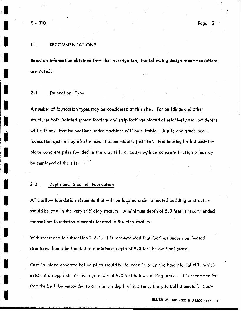
11. RECOMMENDATIONS
Based on information obtained from the investigation, the following design recommendations
are stated. , +
2.1 Foundation Type
A number of foundation types may be considered at this site. For buildings and other
structures both isoloted spread footings and strip footings placed at relatively shallow depths
w i l l suffice. Mat foundations under machines will be suitable. A pile and grade beam
foundation system may also be used if economically justified. End bearing belled cast-in-
place concrete piles founded in the clay till, or cast-in-place concrete frictiqn piles may
be employed at the site. \ . , - .
2.2 Depth and Size of Foundation
All shallow foundation elements that wi l l be located under a heated building or structure
should be cast in the very s t i f f clay stratum. A minimum depth of 5.0 feet is recommended
for shallow foundation elements located in the clay stratum.
With reference to subsection 2.6.1, i t is recornmended that footings under non-heated
structures should be located at a minimum depth of 9.0 feet below final grade.
Cast-in-place concrete belled piles should be founded in or on the hard glacial till, which
exists at an approximate average depth of 9.0 feet below existing grade. It i s recommended
that the bel ls be embedded to a minimum depth of 2.5 times the pile bell diameter'. Cast-
ELMER W. BROOKER & ASSOCIATES LTD.
_...
E - 310 Page 3
in-place concrete friction piles should also be founded in the till stratum. The top 9 feet
of pile ernbeddment should be considered to contribute negligible frictional resistance with
respect to bearing capacity beneath unheated areas, due to frost and seasonal moisture
variation effects. Beneath heated areas,the top 5 feet of p i le embeddment should be
considered to contribute negligible frictional resistance due to moisture variation effects.
Strip and squure footings should have u minimum width of 1.5 and 3.0 feet, respectively.
Piles should be constructed with a minimum shaft diameter of 16 inches.
1
2.3 Design N e t Bearing Values
2.3.1 Static Foundation Loads
a. Spread or Mat Foundations
, , , .'. Spread or mat foundations, resisting static loads, may be designed
using net allowable beariw pressures of 3300 and 4000 pounds per
square foot, for foundation elements founded in the light brown
-7-
silty clay and till, respectively.
b. Cast-In-Place Concrete Piles
End bearing cast-in-place belled piles may be designed to resist
static louds using a net allowable bearing pressure ofJ!O-pounds
per square foot. These piles should be founded in t i l l and be
embedded to a minimum depth of 2.5 times the pile bell diameter.

Page 4 E - 310
Cast-in-place concrete friction piles may be designed to resist
static loads using an allowable skin friction of 500 pounds per I I .
square foot. . .
2.3.2 Dynamic Foundat ion Loads
a . Spread or Mat Foundations
Spread or mat type foundution subjected to dynamic loads #, should
be desgined using reduced net allowable bearing pressures as
follows: Net Allowable Bearing Capacity
Machine Type " Foundation Soil (P.S.F.)
Reciprocating Eng ines Light brown silty clay 825
Centrifugal Engines . A Light brown silty clay 1650
Reciprocating Engines T i l l
Centrifugal Engines T.il.1
1000
2000
In addition to using the reduced net allowable bearing tapacities given
above, machine foundation, either for centrifugal or reciprocating
equipment, should be proportioned on the basis of elastic half space
theory. Allowable amplitudes of movement, frequency ratio and
damping should be taken into uccount. For design considerations of
foundations supporting dynamic loads the following dynamic soils
properties are recommended.
ELMER W. BAOOKER & ASSOCIATES LTD.
E - 310 Page 5
Gd - Dynamic Shear Modulus - 10,000 psi
p - Poisons Ratio - 0.47
These dynamic properties have been inferred from laboratory test
results on representotive samples of the silty clay and t i l l underlying
the site.
, .
b. Cast-in-Place Concrete Piles
End bearing cart-in-place concrete belled piles may be designed
to resist dynamic looding conditionsusing a net allowable bearing
pressure of 3000 pounds per square foot. These piles should be
founded in the till and should be embedded to a minimum depth
of 2.5 times the pile bell diameter. Cast-in-place concrete
friction piles, supporting dynamic loads, may be designed using
an allowable skin friction value of 250 pounds per square foot.
2.4 Lateral Pi le Camcitv
An allowable lateral bearing pressure of 400 pounds per square foot per foot of pile
embeddment length may be used in designing short piles to resist lateral loads. The effective
pile embeddment length should be measured from a point 2 pile diameters below final grade.
2.5 Excavations and Swelling Considerations
2.5.1 N o loose, disturbed, remoulded or slough material should be allowed to remain J
in open footing or pile excavations. Hand cleaning must be undertaken if an
ELMER W. BROOKER & ASSOCIATES LTD.
Page 6 E - 310
acceptable surface cannot be prepared by mechanical equipment. Since the
silty clay and clay till are of stiff consistency, slopes in the order of 20 feet
high are expected to stand vertically for short periods of t ime. However, the
design of cut back side slopes i s controlled by the Workmens Compensation Act
2.5.2
2.6
2.6.1
and a slope of 2 vertical to 1 horizontal i s normally recommended in this type
of material. Deterioration of side slopes with time and possible wet weather
conditions can be expected.
The relatively dry condition of the silty clay and underlying clay till with
respect to their plasticity characteristics, suggests that swelling movements
are probable if free water i s allowed access to these materials.' Constant
volume swelling tests reveal that the swelling potential of the clay i s very
high. Excavations should, therefore, be sheltered from snow, rain, freezing
temperatures and the ingress of free water. A skin codt of concrete, placed
immediately after an excavation i s completed, would be helpful in protecting
the foundation soil from the elements of weather and consequent alteration of
the existing moisture content.
Frost ond Frost Heave
Frost Penetration
The geographic location of the site, with respect to existing freezing index
mops, indicates that the area of the plant site i s subject to a long term average
of approximately 5200 degree days of freezing annually. Considering the soil
types existing on site and allowing for conditions of exposed ground, the
- ELMER W. BROOKER 8 ASSOCIATES LTD.
. .
E - 310 Page 7
&
f
anticipated depth of frost penetration under unheated areas i s 8 to 9 feet.
Therefore, it is recommended that footings under unheated structures should
have a minimum depth of cover of 9 feet.
2.6.2 Frost Heave
The soil materials in their natural state at this site are moisture deficient and
medium to highly plastic. Thus, they are considered to be only moderately
frost unstable and should not heave excessively when frozen. However, i f
drainage is poor and water i s allowed to accumulate in the subsoil, both
rebound heave and/or frost heave may occur. Therefore, well developed site
drainage i s recommended.
2.7 Grade - Supported Floor Slabs
Floor slabs may be supported on grade on the local inorganic silt, clay or clay till. A
leveling course of clean granular material should be placed beneath the grade supported
floor slabs. I t is recommended that the leveling course be kept to a minimum thickness of
about 6 inches and that. site preparation prevent the collection of free water in the leveling
course, which can act as a reservoir. Floor slabs should bestructurally separated from
machine bases and other components of the foundation systems.
2.8 Backfill
g 2.8.1 The local inorganic clay or clay t i l l excavated at the site wi l l be suitable as
random backfill material adjacent to footings and foundation walls. Some
ELMER W. BROOKER & ASSOCIATES LTR.

E - 310 Page 8
moisture conditioning may be necesxlry as the materials; particularly the
clay till, are presently dry of optimum. Random backfill should be placed
in layers not exceeding 6 inches in thickness. Compaction of the backfill
should be to a mean compaction of 95% of Standard Proctor maximum dry
density, with not more than 5% of the tests falling below 93% of Standard
Proctor maximum dry density.
I 2.8.2 The local inorganic clay and clay till mcty also be used as backfill to provide
structural support beneath foundations and adjacent to machine bases.
Compaction of this backfill material must be to a mean dry density of 100%
of Standard Proctor maximum dry density with not more than 10% of the test
results falling below 98% of Standard Proctor maximum dry density.
2.8.3 Frozen backfill or backfill placed on frozen surfaces i s not considered to be
suitable for random backfill adjacent footings, foundation walls, or for
backfill providing structural support. Frozen f i l l material i s considered
suitable only for providing temporary working surfaces from which work can
be carried out.
-8 r - ..:
2.9 Drainage
The site should be sloped to provide positive drainage away from all structures. In order that
erosion by running water is minimized, steep drainage gradients should be avoided. Since the
materials on site are moderately frost susceptible, accumulation of moisture in the subsoil
should be avoided in order that frost heaving i s minimized or prevented.
I .!
I
ELMER V. BROOKER & ASSOCIATES LTD.
E - 310 Page 9
2 . 1 0 Concrete
Type V Sulphate Resistant Portland Cement i s recommended for concrete in contract with the
natural soil A minimum 28 day concrete compressive strength of 3500 pounds per square
inch i s recommended for foundation units.
111. FIELD AND LABORATORY INVESTIGATIONS
Field drill ing was carried out using a Texoma hydraulic dri l l rig, which wus capable of
drilling to a maximum depth of 30 feet. A total of 10 testholes were drilled and logged
on site, with the depth of penetration ranging from 12 feet to 30 feet. The lesser depth
was essentially the depth at which penetration refusal was encountered due to the presence
of a very rocky zone in the t i l l stratum. In addition, two holes which were not logged,
were attempted and abandoned after penetration refusal was met at shallow depths. The
testhole locations are shown on Drawing No. A-2, Appendix A, and detailed logs ore
enclosed as Drawings No. B - 1 to B-10, inclusive, Appendix B. . . , ' .
Disturbed bag samples were taken at approximately 2 foot depth intervals and undisturbed
Shelby tube samples were taken at 5 or 10 foot intervals in the testholes. Standard
Penetration tests were'not carried out as the dri l l r ig was not equipped to perform this test.
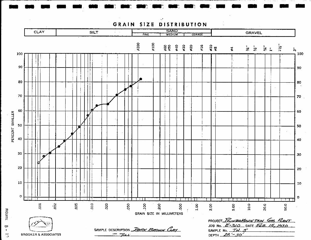
Standard laboratory tests were undertaken on representative samples to determine the
natural moisture content profile, grain size distribution, plasticity indices, unconfined
compressive strength, swelling and consolidation characteristics, compaction characteristics,
and water solubk sulphate content of the subsoil. The results from the preceding tests are
ELMER W. BROOKER & ASSOCIATES LTD.
I E - 310 Page 10
graphically displayed on the testhole logs, on grain size distribution curves presented as
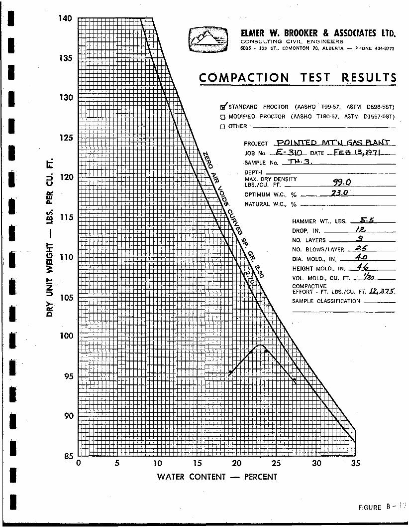
Drawings No. B-11 and B-12, and on a compaction curve, presented as Drawing No. B-13.
A tabular summary of results is included as Drawing No. 8-14,
IV SITE CONDITIONS
The site i s located in the foothil Is areu adjacent to Pointed Mountain, os shown on the key
plan, Drawing No. A-1 . The ground at the site presently slopes to the south and east.
Gullies in the urea are moderately steep and form a drainage network leading to Fishermans
Lake. Good site drainage may be readily achieved through proper site grading. The area is
thickly wooded with mature poplar and a few spruce trees. Approximately 6 inches of moss
and organic cover exists over the entire site.
At the time of the investigation approximately 18 inches of snow cbvered the site and the
depth of frost penetrarion was noted to be approximately 3 feet. Permafrost was not
encountered in any of the testholes.
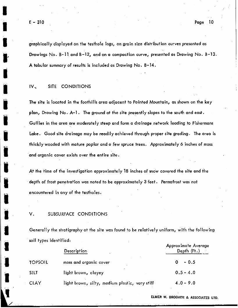
V. SUBSURFACE CONDITIONS
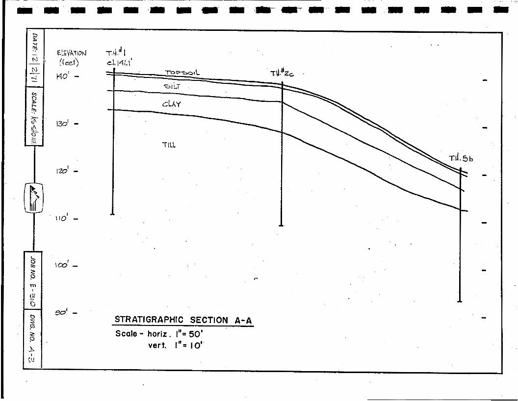
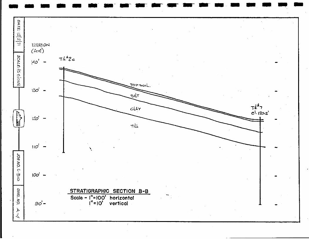
Generally the stratigraphy at the site was found to be relatively uniform, with
soil types identified:
Description
TOPS01 L moss and organic cover
the following
Approximate Average Depth (Ft .)
0 - 0.5
SILT light brown, clayey 0.5 - 4.0
CLAY light brown, silty, medium plastic, very stiff 4.0 - 9.0
ELMER W. BROOKER & ASSOCIATES LTD.

E - 310 Page 11
TI 11 dark brown, silty, clayey, with stones and rust spots, becoming more silty and less-stoney with depth, medium plastic, hard 9.0 - End of Hole
NOTE: 1 . The maximum depth of testhole penetration was 30 feet.
I 2 . Penetration refusal was met in several of the testholes at approximately the 12 foot depth where a very rocky zone was encountered in the til I . , .
3. No groundwater was observed in any of the testholes which
4. The depth of frost penetration was found to be approximately
were checked at intervals of 2 and 8 hours after drill ing.
3 feet.
c Two stratigraphic sections are included as Drawings No. A-3 and A-4, Appendix A.
c c c
VI. LIMITATIONS
Information presented herein i s based on the findings in ten testholes. Similar conditions
were observed in each testhole, indicating that noted conditions are .believed to be
representative of the entire site. However, since the maximum depth of penetration was
limited to 30 feet and there may be considerable excavation carried out in levelling the
site, the effective depth of investigation w i l l b e correspondingly reduced. Consequently,
if conditions other then those-presented here-in are noted during construction, we should
be notified in order that our recommendations may be evaluated in light of new findings.

E - 310
Respectfully Submitted,
ELMER W. BROQKER
Lawrence A. Bolanko,
Gurry R. Gilchrist, P.
LAB:sjw
Page 12
I
ELMER W. BROOKER & ASSOCIATES LTD.

' .
KEY PLAN

JOB NO. E - 310 SUMMARY OF RESULTS
1- HOLE UNCONFINED COMPRESSION TEST
" I WET I WATER I COMPRESSIVE I FAILURE OTHER TESTS IDENSITY I CONTENT i STRENGTH I STRAIN REMARKS
figure see
1138.0 I 12.0 1 5.63 I 7.87 1 2 - 138
12- 133
28 - 294
2 4 - 6
2 28 - 30
4 22
5 6
Direct Shear
31.2 1 f I I 17.4 50.0 18.7
13.5 38.0 14.5
SOLUBLE SULP -!ATE I* 28 - 30 ' 23.5 I
140
135
130
125
t 5 120
E U
6
115 4
I r s2 110
I-
5 != 2 .
105 2 n
100
9s
90
ELMER W. BROOKER .& ASSOCIATES LFD, CONSULTING C I V I L ENGINEERS 6035 - 103 ST., EDMONTON 70, ALBERTA - PHONE 434.8773
COMPACTION TEST RESULTS -
dSTANDARD PROCTOR (AASHO ' T99-57, ASTM D698-58T)
0 MODIFIED PROCTOR (AASHO T180-57, ASTM 01557-58T)
PROJECT - P O I W E D MT*a- 9 A m JOB No. E- qm DATE FF 13: 197 ! SAMPLE No. 3 .
MAX. DRY DENSITY LBS./CU. FT. 99.0 OPTIMUM W.C., % 23.0 NATURAL W*C., %
HAMMER WT., LBS. 5. r DROP, IN. A NO. LAYERS -3 NO. BLOWS/LAYER 25 DIA. MOLD., IN. 4Q HEIGHT MOLD., IN. 44 VOL. MOLD., CU. Ff. COMPACTIVE EFFORT - FT. LSS./CU. FT. &a SAMPLE CLASSIFICATION
-
5 10 15 20 25 WATER CONTENT - PERCENT
30 35
r- "
.-
. ..
O'O
Z
0.0 r
003
OO
'Z
00' I
OGO'
020'
010'
GOO' FIGU
RE
B - 1'

P#
8#
OI#
9I#
OZ#
OW
OW
0s # 09x
001 #
0.05
O'O
Z
0'0 1
OO
'G
00'2
00' 1
0
0
0
0
0
0
2 m
m
h
W
Ln s
0
0
m
0
N
0
4
tl3llWW
S IN33U
3d
001;' ;
+ w
E
002' 5
N
w
rn
050'
OZO'
010'
500-
ZOO'
100'
i VI
w c
i U I I It ci ci
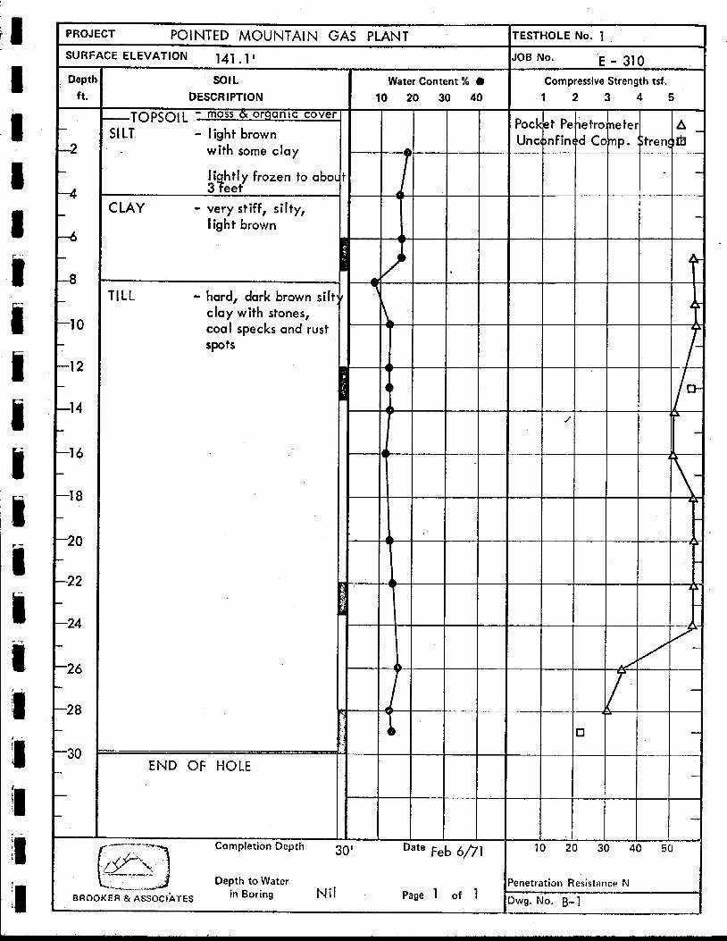
PROJECT POINTED MOUNTAIN GAS PLANT
SURFACE ELEVATION 141.1 I - Deptl
ft. -
-2
-4
-6
-a
-1 0
-1 2
-1 4
-1 6
-1 8
-20
-2 2
-24
-2 6
-2 8
-30
SOIL DESCRIPTION
-TOPSOIL moss d omanlc cover
SILT - light brown with some clay
3Qeet li htly frozen to abol
CLAY - very stiff, silty, I igh t brown
TILL - hard, dark brown silt clay with stones, coal specks and rust spots
END OF HOLE
Water Content 56 0 10 20 30 40
te Feb 6/71
Page 1 of 1
IOB No. E - 310 Compressive Strength tsf.
1 2 3 4 5
/
10 20 30 40 50
metration Resistance N
i L
wg. No. B-1
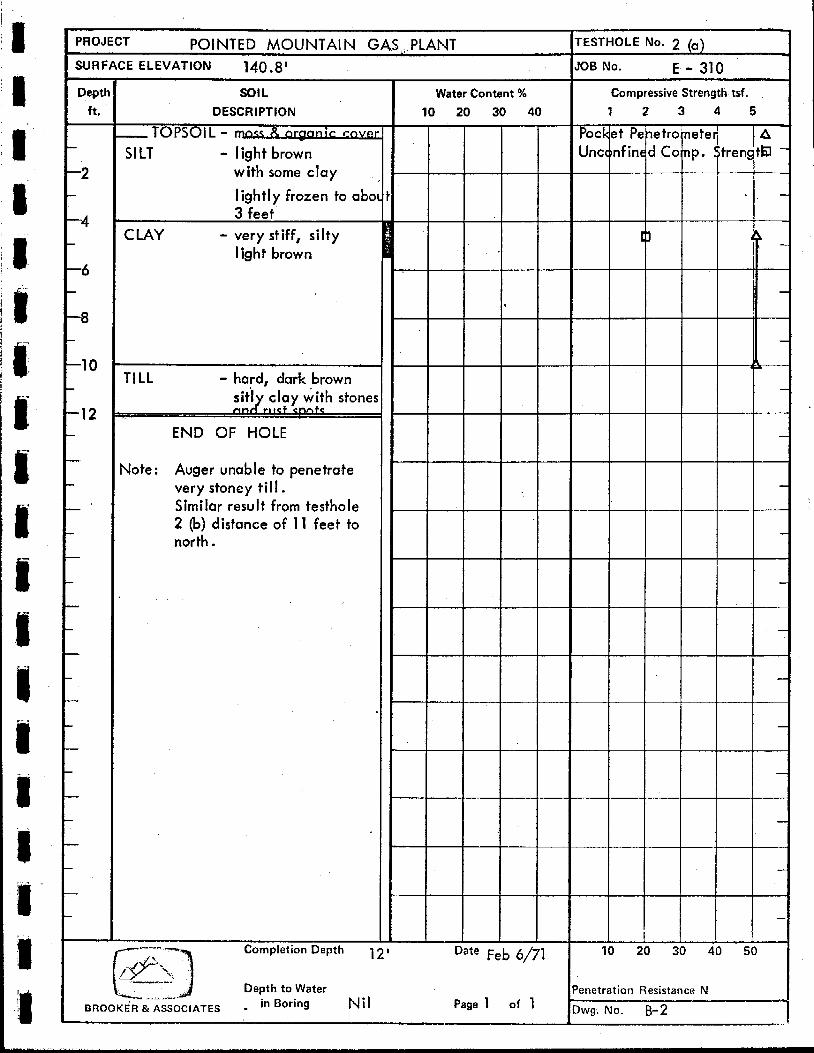
PROJECT POINTED MOUNTAIN GASA, PLANT SURFACE ELEVATION 140.8'
SOIL DESCRIPTION
-TOPSOIL - -ic r w
SILT - light brown with some clay
lightly frozen to abo 3 feet
C LAY - very stiff, silty I ish t brown
TILL - hard, dark brown s i t i clay with stone! rrn rltqt c n n t q
END OF HOLE
qote : Auger unable to penetrate very stoney till. Similar result from testhole 2 (b) distance of 11 feet to north.
Water Content % 10 20 30 40
tESfHOLE No. 2 (a)
JOB No. E - 310
Compressive Strength tsf.
1 2 3 4 5
Pocket PI Unconf in
10 :
le tro nete( Conp. Streng
30 40 5
'enetration Resistance N
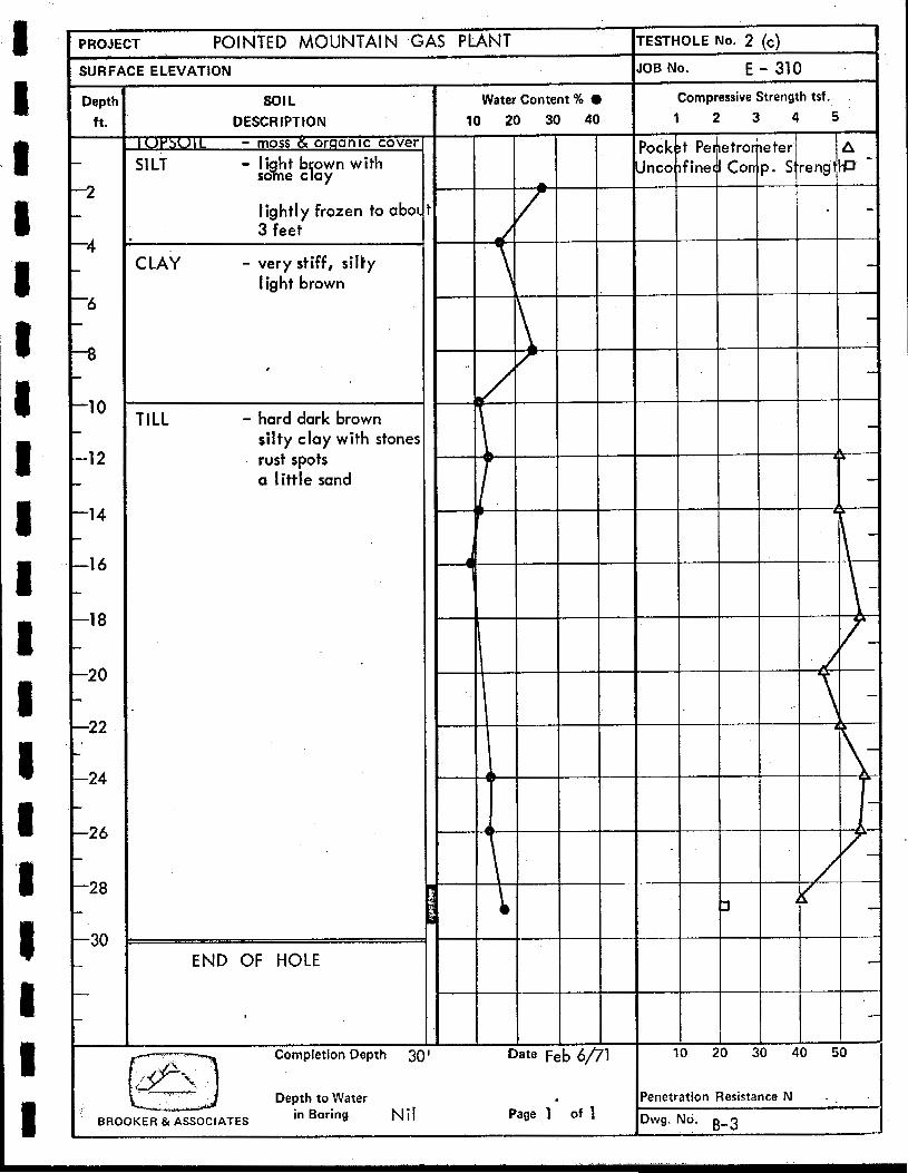
PROJECT POINTED MOUNTAIN GAS PLANT TESTHOLE NO. 2 (c)
SURFACE ELEVATION 7
Depth ft. -
-2
-4
-6 -
-8
-1 0
-1 2 ..
-1 4 -
-1 6 -
-1 8 - -20 9
-22
-24 - -26 -
-28 ...
-30 -
- -
-
s o l L DESCRIPTION
U I L - moss & organic cover
so e c ay
lightly frozen to obol 3 feet
SILT - lignht brown with
CLAY - very stiff, silty I ig h t brown
TILL - hard dark brown silty clay with stones rust spots a little sand
END OF HOLE " . -. . .. .
JOB No. E - 310
Water Content 46 0 Compressive Strength tsf.
10 20 30 40 1 2 3 4 5
END OF HOLE
Note: Abondoned, too stoney for auger to penetrate
Completion Depth L
13' Date
Feb 6/71
Depth to Water
BROOKER &ASSOCIATES in Boring Nil Page 1 of 1
ZEE 10 20 30 1
enetration Resistance N

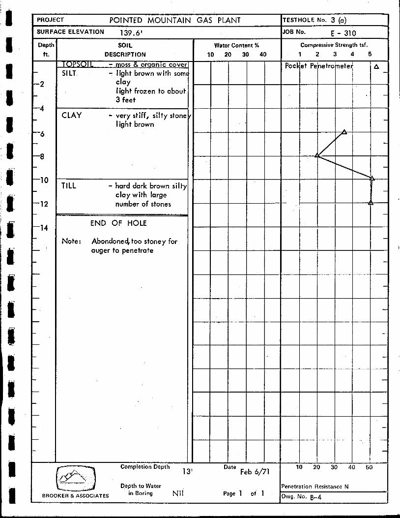
PROJECT POINTED MOUNTAIN GAS PLANT ITESTHOLE No. 3 (b) SURFACE ELEVATION 139 -6' JOB NO. E - 310
Depth
ft. - -2
-4
-6
-8
-10
-12
-14
SOIL DESCRIPTION
- TOPSOI L - WCC - i r . c n v a
SILT - light brown with soml clay lightly frozen to abol 3 feet
CLAY - very stiff, silty, stoney light brown
TILL - hard dark brown silty clay with large number of stones
Note: Abandoned, too stoney for auger to penetrate
(3c) Abandoned at 3;' .for Same reason
Water Content % I Compressive Strength tsf
10 20 30 40 1 2 3 4 5
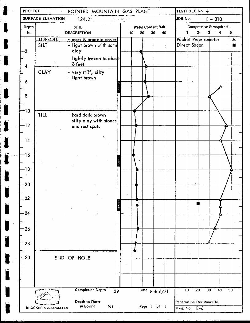
PROJECT POINTED MOUNTAIN GAS PLANT SURFACE ELEVATION 124.2' ," - ,. .. ~ '
Oept
ft. -
-2
-4
-6
-8
-1 0
-12
-1 4
-1 6
-18
-20
-22
- 24
- 26
- 28
- 30
-
SOIL DESCRIPTION
TnPSQl I I ss & -le C O M
SILT' - I ight brown with soml clay
lightly frozen to abol 3 feet
C LAY - very stiff, silty I ight brown
TILL - hard dark brown silty clay with stones and rust spots
Water Content %O 10 20 30 40
. . . .. . . .. . .. ". - - .
END OF HOLE
Date Feb 6/71
Page 1 of 1
'ESTHOLE No. 4 OB No. E - 310
Compressive Strength tsf.
1 2 3 4 5
20 30 40 E
enetration Resistance N
Iwg. NO. B-6
'I I
I
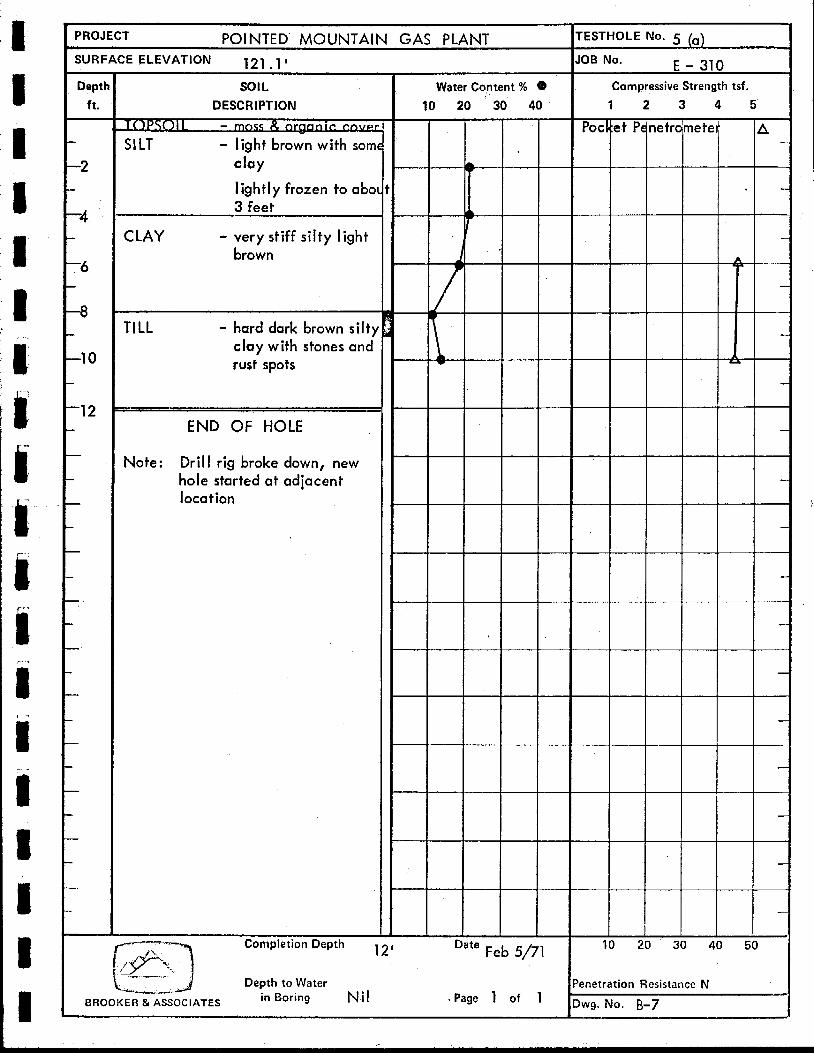
PROJECT POINTED' MOUNTAIN GAS PLANT TESTHOLE No. 5 (a)
IOB No. E - 310 Compressive Strength tsf.
1 2 3 4 5
SURFACE ELEVATION 121 1 I ". . .
SOIL DESCRIPTION
SILT - light brown with som clay
lightly frozen to abo 3 feet
Water Content %
10 20 30 40
C LAY - very stiff silty light brown
TILL - hard dark brown silt) clay with stones and rust spots
END OF HOLE
Drill rig broke down, new hole started at adjacent location
Note :
Completion Depth te Feb 5/71 10 20 30 I
Depth to Water in Boring Nil . Page
enetration Resistance N 1 of 1 BROOKER & ASSOCIATES
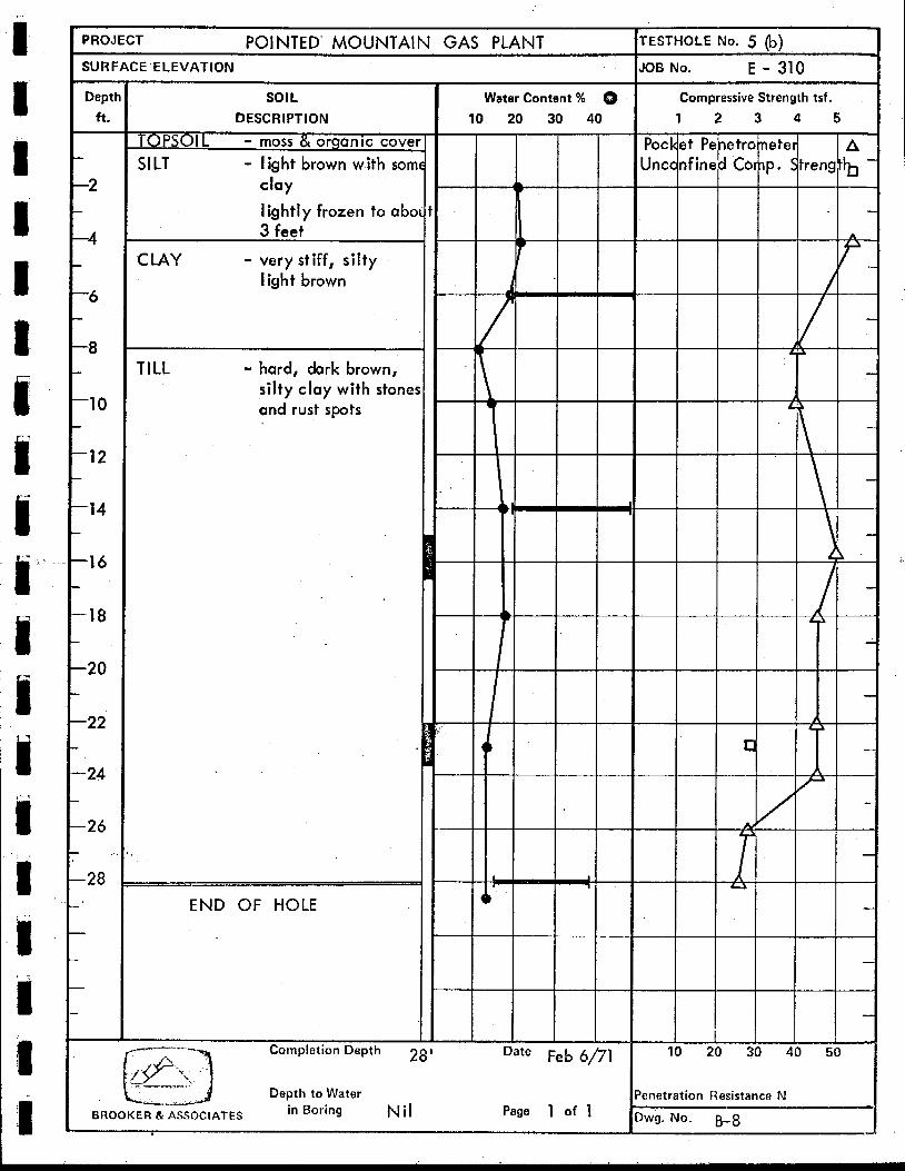
PROJECT POINTED' MOUNTAIN GAS PLANT 'ESTHOLE No. 5 (b) OB No. E - 310
Compressive Strength tsf.
1 2 3 4 5
SURFACE ELEVATION - Deptl
ft. - I
-2 -
-4
-6 I
-8 *
-1 0
-12 -
-1 4
-1 6
-18
-20
-22
-24
-26
-28
-
I
Water Content % 8 10 20 30 40
sot L DESCRIPTION
TOPSOIL - moss & organlc cove1
SILT - light brown with som clay
lightly frozen to abo 3 feet
CLAY - very stiff, silty i igh t brown
pot Jnc -
;t Pe7etronete I f ined Corlp . I
I
A
n
LI
20 30 4
TILL - hard, dark brown, silty clay with stone! and rust spots
c
END OF HOLE
Date Feb 6,
metration Resistance N Wg. No, B-8 Page 1 of 1 BHOOKER &ASSOCIATES
I
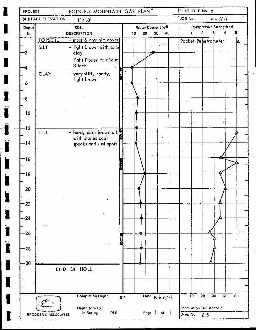
PROJECT POINTED’ MOUNTAIN GAS PLANT
114 .O’ sol L
DESCRIPTION
TOPSOIL - moss- & organic cover
SILT - light brown with som clay
light frozen to about 3 feet
CLAY - very stiff, sandy, I ig h t brown
TILL - hard, dark brown sill . .
with.stones coal specks and rust spots
END OF HOLE
Completion Depth
Depth to Water in Boring Nil
Water Content %e 10 20 30 40
30’ Feb 6/71
I Page 1 of 1
”
ESTNOLE No. 6 3B No. E - 310
Compressive Strength tsf.
1 2 3 4 5
10 20 30 40 50
’enetration Resistance N
)wg. No. 6-9

,8
-1 0
‘12
-14
- 1 d
- l €
- 2(
- 2: -
- 24 - - 2t
sol L DESCRIPTION
>PSO\L - moss & organic cover
LT - light brown with somc clay
lightly frozen to abol t 3 feet
,LAY - very stiff, silty, light brown
rlLL - hard dark brown silty clay with stones coal specks and rust spots
L E
. END OF HOLE

I
I
2
ts 8
-
ai I I
0
. . ..
.. .. .. "".,"*
I t
1
c
I
9
I
I w
u)
a
I- cn
I
13 1
I I
I
I I
I I
I I