the “pwm switch” in mode transitioning spice...
TRANSCRIPT

ON Semiconductor
The “PWM Switch” in mode transitioning SPICE models
PCIM Germany 2005
Christophe Basso - Application Manager

November 2001 Christophe Basso – PCIM 2005www.onsemi.com
2
The The ““PWM SwitchPWM Switch”” in mode transitioning SPICE modelsin mode transitioning SPICE models
Agenda
Why average simulations?What techniques already exist?The PWM Switch conceptThe voltage-mode caseThe current-mode caseChecking averaged model’s validityConclusion

November 2001 Christophe Basso – PCIM 2005www.onsemi.com
3
The The ““PWM SwitchPWM Switch”” in mode transitioning SPICE modelsin mode transitioning SPICE models
Unveil open-loop ac response for stabilization purposesHelps to assess impact of stray elements variations on stabilityCan predict transient response with large-signal modelsSimulation time is quick as frequency component fades away
Why average simulations?

November 2001 Christophe Basso – PCIM 2005www.onsemi.com
4
The The ““PWM SwitchPWM Switch”” in mode transitioning SPICE modelsin mode transitioning SPICE models
What techniques already exist?StateState--Space AveragingSpace Averaging (SSA)Introduced by Slobodan Ćuk in the 80’Long and painful processFails to predict sub-harmonic oscillations
uL
xLdt
dx 1211+−=
2.
1112 xCoutRload
xCoutdt
dx−=
211 xLdt
dx−=
2.
1112 xCoutRload
xCoutdt
dx−=
VoutL
C R
x1
x2u1
VoutL
C R
x1
x2
offon
Apply smoothing process Linearize
Pfffff!

November 2001 Christophe Basso – PCIM 2005www.onsemi.com
5
The The ““PWM SwitchPWM Switch”” in mode transitioning SPICE modelsin mode transitioning SPICE models
What techniques already exist?The GSIMGSIM conceptIntroduced by Sam Ben-Yaakov in the 90’Easy to derive but not fully invariant (dual inductors converters?)Fully auto-toggling mode modelsFails to predict sub-harmonic oscillations
b c
Lf
on off
V(a
,b)
V(a
,c)
Fsw
a
Vin C R
Ib Ic
Ia
a
b
c
Lf
on
off
V(a,b)
V(a,c)
Fsw

November 2001 Christophe Basso – PCIM 2005www.onsemi.com
6
The The ““PWM SwitchPWM Switch”” in mode transitioning SPICE modelsin mode transitioning SPICE models
What techniques already exist?The CoPECCoPEC modelIntroduced by the Colorado Power Electronic Center in the 90’Easy to derive and fully invariantFully auto-toggling mode modelsFails to predict sub-harmonic oscillations
i1(t)
i12(t)
v1(t) v2(t)
Q1 D1
d(t)
i1(t)
v1(t) v2(t)
i12(t)
D':D
i1(t)
i12(t)
v1(t) v2(t)
Q1 D1
d1(t)
i1(t)
v1(t) v2(t)
i12(t)
Re(d1) I2
I2=(Re x i1^2) / v2
CCM DCM

November 2001 Christophe Basso – PCIM 2005www.onsemi.com
7
The The ““PWM SwitchPWM Switch”” in mode transitioning SPICE modelsin mode transitioning SPICE models
What techniques already exist?The RidleyRidley modelsIntroduced by Raymond Ridley from VPEC in the 90’Use z-transform methodNo auto-toggling mode modelsCan only work in acCan predict sub-harmonic oscillations in CCM
1
Rload3
5
Resr100m
Cout220uF
2
VgAC = 0
Vout
4
DutyV2AC = 1
3
Vin Vout
Gnd Ctrl
AC model
DRS = 20mFS = 50kVOUT = 5RL = 3VIN = 11X1RI = 0.33L = 37.5u
0
0
0
0.458 0

November 2001 Christophe Basso – PCIM 2005www.onsemi.com
8
The The ““PWM SwitchPWM Switch”” in mode transitioning SPICE modelsin mode transitioning SPICE models
What techniques already exist?The PWM SwitchPWM SwitchIntroduced by Vatché Vorpérian in the mid-80’Easy to derive and fully invariantNo auto-toggling mode modelsCan predict sub-harmonic oscillations in CCMDCM model was never published!
ca
p
d
d'
Ia(t) Ic(t)
Vap(t) Vcp(t)
a c
PWM switch p
d
d'
Vin
L
C R Vout

November 2001 Christophe Basso – PCIM 2005www.onsemi.com
9
The The ““PWM SwitchPWM Switch”” in mode transitioning SPICE modelsin mode transitioning SPICE models
The PWM Switch concept
Vin
L
C R Voutac
PW
M s
witc
hp
d
d'
Linear network
Linear network
off
on
diode + transistor = guilty for non-linearity!What do you plead?

November 2001 Christophe Basso – PCIM 2005www.onsemi.com
10
The The ““PWM SwitchPWM Switch”” in mode transitioning SPICE modelsin mode transitioning SPICE models
The PWM Switch concept
1
4
2
Q1
5
Rb_upper1Meg
Rb_lower100k
Vg
Vout
8
3
7
h11 Beta.Ib
Rc10k
Re150
Ce1nF
ReqRb_upper//Rb_lower
b c
e
ib ic
ie
VinRc10k
Re150
Ce1nF
Vin
Vout
Ve
Remember the bipolarsEbers-Moll model…
Replace Q1 by its small-signal model

November 2001 Christophe Basso – PCIM 2005www.onsemi.com
11
The The ““PWM SwitchPWM Switch”” in mode transitioning SPICE modelsin mode transitioning SPICE models
An invariant association
a c
PWM switch p
d
d'
Vin
L
C R Vout
Vin
L
C R Voutac
PW
M s
witc
hp
d
d'
Vin
LC R Vout
ac
PWM
sw
itch
p
d
d'
ca
p
d
d'
Ia(t) Ic(t)
Vap(t) Vcp(t)
Buck
BoostBuck-boost
November 2001 Christophe Basso – PCIM 2005www.onsemi.com
12
The The ““PWM SwitchPWM Switch”” in mode transitioning SPICE modelsin mode transitioning SPICE models
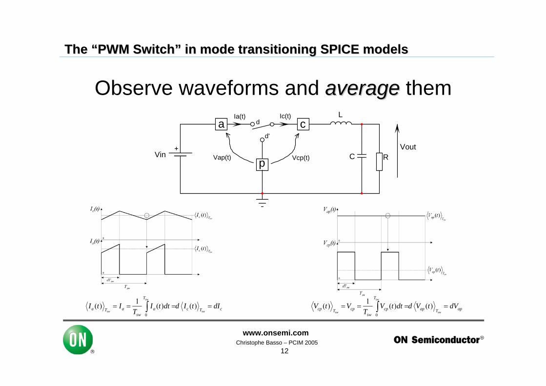
Observe waveforms and averageaverage themca
p
d
d'
Ia(t) Ic(t)
Vap(t) Vcp(t)Vin
L
C RVout
0
1( ) ( ) ( )sw
sw sw
T
a a a c cT Tsw
I t I I t dt d I t dIT
= = = =∫0
1( ) ( ) ( )sw
sw sw
T
cp cp cp ap apT Tsw
V t V V t dt d V t dVT
= = = =∫

November 2001 Christophe Basso – PCIM 2005www.onsemi.com
13
The The ““PWM SwitchPWM Switch”” in mode transitioning SPICE modelsin mode transitioning SPICE models
PWM Switch model in CCM: a 1:D transformer!
ca
p
Ia(t) Ic(t)
V=d.V(a,p)
p
I=d.Ic
ca
p
Ia(t) Ic(t)
1 dVap Vcp
Large-signal (non-linear) model

November 2001 Christophe Basso – PCIM 2005www.onsemi.com
14
The The ““PWM SwitchPWM Switch”” in mode transitioning SPICE modelsin mode transitioning SPICE models
Use it immediately, SPICESPICE linearizes it for you!
L
d
100uH
Vbias0.4AC = 1
C1100u
R110
Vout
Vin10
a
cp10.0 10.0
16.7
0.400
Always verify the dc operating point!

November 2001 Christophe Basso – PCIM 2005www.onsemi.com
15
The The ““PWM SwitchPWM Switch”” in mode transitioning SPICE modelsin mode transitioning SPICE models
The original CCM/DCM PWM Switch models
CCM: common « passive »
a
c
pd1 d2
d3
a c
p
d 1-d
DCM: common « common »
Looks likeauto-toggling
is impossible…
( )apv t ( )cpv t
( )cpv t( )acv t

November 2001 Christophe Basso – PCIM 2005www.onsemi.com
16
The The ““PWM SwitchPWM Switch”” in mode transitioning SPICE modelsin mode transitioning SPICE models
Deriving the DCM PWM Switch in common « passive »
ca
p
d1
d2
Ia(t) Ic(t)
Vap(t) Vcp(t)Vin
L
C RVout
d3
IaIpeak
Vap
Ipeak
Ic
VcpVap
Vcp
d1Tsw d2Tsw d3Tsw
t
t
t
t
IaIpeak
Vap
Ipeak
Ic
VcpVap
Vcp
d1Tsw d2Tsw d3Tsw
t
t
t
t
1
2peak
a
I dI =
( )1 2 1 2
2 2 2peak peak peak
c
I d I d I d dI
+= + =
( ) ( )1 2 1 2
1 1
22
ac a
d d d dII Id d
+ += =
1
2peak
a
I dI =
( )1 2 1 2
2 2 2peak peak peak
c
I d I d I d dI
+= + =
( ) ( )1 2 1 2
1 1
22
ac a
d d d dII Id d
+ += =

November 2001 Christophe Basso – PCIM 2005www.onsemi.com
17
The The ““PWM SwitchPWM Switch”” in mode transitioning SPICE modelsin mode transitioning SPICE models
An auto-toggling version: clamp the equation!
ca
p
Ia(t) Ic(t)
1 NVap Vcp
N=d1/(d1+d2)
12 1
1 1
2 ² 2c ac sw sw c
ac sw ac
I L V d T LF Id dV d T d V−
= = −Model input
Clamp d2:d2 CCM = 1- d1
d2 DCM = 1- d1- d3
d2 < d2 CCMmodel is in DCM!

November 2001 Christophe Basso – PCIM 2005www.onsemi.com
18
The The ““PWM SwitchPWM Switch”” in mode transitioning SPICE modelsin mode transitioning SPICE models
In voltage mode, add the PWM modulator gain
3
V410
4
L175u
17d
a c
PWM switch VM p
X4PWMCCMVM
GAI
N
XPWMGAINK = 0.5
5.0
10.0
5.00
0.500 1PWM
peak
KV
=

November 2001 Christophe Basso – PCIM 2005www.onsemi.com
19
The The ““PWM SwitchPWM Switch”” in mode transitioning SPICE modelsin mode transitioning SPICE models
Testing the auto-toggling modelVout
2
Cout100uIC = 0
Resr70m3
V410
4 17
L175u vout
vout
5
7
RupperRupper
Rlower10k
8
6
X2AMPSIMPVHIGH = 1.9
V22.5
Verr
13
R3R3
C3C3
14
R2R2
C1C1
C2C2
d
a c
PWM switch VM p
X10PWMVM2L = 75uFs = 100k
R520m 4.99
4.99
10.0
4.99
0.499
2.50
2.50
5.00
0.329
GA
IN XPWMGAINK = 0.5
19
XstepPSW1
Vstep
Vout
16
Cout100uIC =
Resr70m
10
V410
1 4
L175uIC =
7
X2PSW1
D2N = 0.01
R420m
vout
+-
36
X8COMPAR
VsawTran Generators = PULSE
13
RupperRupper
Rlower10k
8
X1AMPSIMPVHIGH = 1.9
V22.5
Verr
18
R3R3
C3C3
19
R2R2
C1C1
C2C2
vout
20
XstepPSW1 Vstep
Averaged model Cycle-by-cycle

November 2001 Christophe Basso – PCIM 2005www.onsemi.com
20
The The ““PWM SwitchPWM Switch”” in mode transitioning SPICE modelsin mode transitioning SPICE models
Comparing results with a stepload…
4.60
4.80
5.00
5.20
5.40
,
9.75m 11.2m 12.7m 14.2m 15.7mtime in seconds
300m
500m
700m
900m
1.10
Cycle-by-cycle
Averaged model
Cycle-by-cycle
Averaged model
Output voltage
Error voltage I can’t believethis result…

November 2001 Christophe Basso – PCIM 2005www.onsemi.com
21
The The ““PWM SwitchPWM Switch”” in mode transitioning SPICE modelsin mode transitioning SPICE models
Current-mode PWM switchSame approach as before:
observe and average waveformsget the equivalent representationperturb for small-signal analysis
CCM DCM

November 2001 Christophe Basso – PCIM 2005www.onsemi.com
22
The The ““PWM SwitchPWM Switch”” in mode transitioning SPICE modelsin mode transitioning SPICE models
CCM operation, current expression
1
2
3
'( )( ) ( ) ( )
2
(1 )2
f swc i c sw e
c sw e swc cp
i i
S d t TI t R V t d t T S
V T S TI d V dR R L
= − −
= − − −
1 2
3
ca
p
Ia(t) Ic(t)
I=Vc/Ri
p
I=d.Ic I=Iu Cs
'( )( ) ( ) ( )
2
(1 )2
f swc i c sw e
c sw e swc cp
i i
S d t TI t R V t d t T S
V T S TI d V dR R L
= − −
= − − −
1 2
3
ca
p
Ia(t) Ic(t)
I=Vc/Ri
p
I=d.Ic I=Iu Cs

November 2001 Christophe Basso – PCIM 2005www.onsemi.com
23
The The ““PWM SwitchPWM Switch”” in mode transitioning SPICE modelsin mode transitioning SPICE models
DCM operation, current expression1c sw e
peaki
V d T SIR
− ×=
12
c sw ec sw f
i
V d T SI d T SR
α−= −
( )1 2 1 2
2 2 2peak peak peak
c
I d I d I d dI
+= + =
ca
p
Ia(t) Ic(t)
I=Vc/Ri
p
I=(d1/(d1+d2)).Ic I=Iu
1 1 22
( , ) 12
d Tsw Se d dV c pI d TswRi L
µ × × +⎛ ⎞= + × × × −⎜ ⎟⎝ ⎠

November 2001 Christophe Basso – PCIM 2005www.onsemi.com
24
The The ““PWM SwitchPWM Switch”” in mode transitioning SPICE modelsin mode transitioning SPICE models
The PWM SwitchPWM Switch, the final encapsulation
Vout
16
Cout220uF
Resr70m
V425
1 4
L175u
vout
9
d
a c
PWM switch CM p
duty-cycle2
X1PWMDCMCM
duty_cycle
R420m
10
X5PSW1
V2
6
R710k
R810k
7
8
X4AMPSIMP
V62.5
vout
Y4
L41p
11
C31p
V7AC = 1
12
R120k
C110n
C2470p
Vout
16
Cout220uFIC = 4.6
Resr70m
V425
1 4
L175uIC = 250m
voutR41
12
X2PSW1
2
V1
10+-
614
13
X3COMPAR
17
R3470
C1x100p
B1Voltage
V(4,vout)
D11n5818
18
R710k
R810k
19
X4AMPSIMP
V62.5
vout
Verr
24
R120k
C110n
C2470p
20
X5PSW1
V2
S
R
Q
Q
A buck: averaged model vs cycle-by-cycle

November 2001 Christophe Basso – PCIM 2005www.onsemi.com
25
The The ““PWM SwitchPWM Switch”” in mode transitioning SPICE modelsin mode transitioning SPICE models
Good matching between both models
Error voltage
Output voltage
It can’t be, he is cheating!

November 2001 Christophe Basso – PCIM 2005www.onsemi.com
26
The The ““PWM SwitchPWM Switch”” in mode transitioning SPICE modelsin mode transitioning SPICE models
Testing the ac response
2
Vin126
1 4
X1xXFMRRATIO = -0.1
D1MBR140P
6
L12.2uH
Rs10m
Rload149
R17300m
C210uF
15
R4100m
C1470uF
5
R151.5k
10
16
out1
14
LoL1kH
12
CoL1kF
VstimAC = 1
out2
13
X3TL431
Rlow1k
Rupp3.9k
out2
Cf100nF
7
R5100m
C5470uF
out1
Vout
vcac
PW
M s
witc
h C
Mp
duty
-cyc
le
3
18
PWMCMX1L = 1.8mFs = 66kRi = 1.5
dc
L31.8m
11
V34.8
R78k
VFB
126
-127
12.7
12.2 12.2 12.2
12.212.2
10.6
9.88
0.6490.649
0
2.50
12.2
0
0.649
0.408
4.80
A dcm current-mode flyback
November 2001 Christophe Basso – PCIM 2005www.onsemi.com
27
The The ““PWM SwitchPWM Switch”” in mode transitioning SPICE modelsin mode transitioning SPICE models
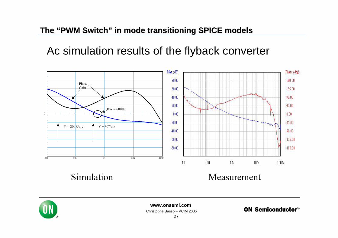
10 100 1K 10K 100K
0
Y = 20dB/div Y = 45°/div
Phase Gain
BW = 600Hz
Simulation Measurement
Ac simulation results of the flyback converter

November 2001 Christophe Basso – PCIM 2005www.onsemi.com
28
The The ““PWM SwitchPWM Switch”” in mode transitioning SPICE modelsin mode transitioning SPICE models
If the load increases…
-20.0
0
20.0
40.0
60.0
vdbf
b in
db(
volts
)pl
ot1
1
10 100 1k 10k 100kfrequency in hertz
60.0
100
140
180
220
ph_v
fb in
deg
rees
Plo
t2
2
CCM operation
Sub-harmonic oscillations!
phase
gain

November 2001 Christophe Basso – PCIM 2005www.onsemi.com
29
The The ““PWM SwitchPWM Switch”” in mode transitioning SPICE modelsin mode transitioning SPICE models
Testing on a multi-output forward
parametersRsense=0.35Vout=28L1=130uL2=130uN1=0.5N2=0.215
Rupper=(Vout-2.5)/250ufc=5kpm=50Gfc=8.84pfc=-66
G=10^(-Gfc/20)boost=pm-(pfc)-90pi=3.14159K=tan((boost/2+45)*pi/180)C2=1/(2*pi*fc*G*k*Rupper)C1=C2*(K^2-1)R2=k/(2*pi*fc*C1)
Vout1
6
Cout148u
Resr1245m
11 3
L1L1
13
RupperRupper
Rlower10k
18
V32.5
19
Verrx
R970m
20
R2R2
C1C1
C2C2
X4AMPSIMP
vc
a c
PWM switch CM p
duty-cycle
10 8
1
X5PWMCM2L = L1/N1^2+L2/N2^2Fs = 200kRi = RsenseSe = 0
X6XFMRRATIO = N1V6
160
dc
9 Vout2
2
Cout2100u
Resr2100m
4 5
L2L2
R2x70m
Rload26
X1XFMRRATIO = N2
vout
vout
LoL1kH
7
CoL1kF
Rload17
V1AC = 1
X7XFMRRATIO = N1/N2
28.0
28.0
28.3 28.3
2.50
2.500.861
0.861
160 56.6
0.861
0.356
12.0
12.0
12.2 12.2
0
Coupled inductances
28 V
12 V
A multi-output forward

November 2001 Christophe Basso – PCIM 2005www.onsemi.com
30
The The ““PWM SwitchPWM Switch”” in mode transitioning SPICE modelsin mode transitioning SPICE models
Output voltage bang on the 28 V output…
27.2
27.6
28.0
28.4
28.8
vout
, vou
t1 in
vol
tsPl
ot1
13
3.93m 4.83m 5.74m 6.64m 7.55mtime in seconds
11.7
11.9
12.1
12.3
12.5
vout
2#a
in v
olts
11.6
11.8
12.0
12.2
12.4
vout
2 in
vol
tsPl
ot2
24
A forward converter
Inductances arecoupled…
28 V
12 V
Cycle-by-cycleAveraged

November 2001 Christophe Basso – PCIM 2005www.onsemi.com
31
The The ““PWM SwitchPWM Switch”” in mode transitioning SPICE modelsin mode transitioning SPICE models
Output voltage bang on the 28 V output…
A forward converter
Inductances areun-coupled…
27.2
27.6
28.0
28.4
28.8
vout
, vou
t1 in
vol
tspl
ot1
14
3.83m 4.75m 5.68m 6.61m 7.54mtime in seconds
11.2
11.6
12.0
12.4
12.8
vout
2, v
out2
#a in
vol
tsP
lot2
23
28 V
12 V
Cycle-by-cycleAveraged

November 2001 Christophe Basso – PCIM 2005www.onsemi.com
32
The The ““PWM SwitchPWM Switch”” in mode transitioning SPICE modelsin mode transitioning SPICE models
Instability in the buck DCM current-mode
1 10 100 1k 10k 100k 1Megfrequency in hertz
-80.0
-40.0
0
40.0
80.0vd
bout
, vdb
out#
1, v
dbou
t#2
in d
b(vo
lts)
-180
-90.0
0
90.0
180
vpho
ut, v
phou
t#1,
vph
out#
2 in
deg
rees
Plo
t1
1
2
3
4
5
6
Phase Vin = 7 V Rload = 100 Ω
Phase Vin = 7.5 V Rload = 50 Ω
Gain Vin = 7.5 V Rload = 50 Ω
Phase Vin = 10 V Rload = 50 Ω
Gain Vin = 7 V Rload = 100 Ω
Gain Vin = 10 V Rload = 50 Ω
Vin = 7V M = 0.71 Vin = 7.5V M = 0.66 Vin = 10V M = 0.5
The DCM buckshows instability
as M > 0.66without ramp
> 20 dB increase
Phase jumps to –180°

November 2001 Christophe Basso – PCIM 2005www.onsemi.com
33
The The ““PWM SwitchPWM Switch”” in mode transitioning SPICE modelsin mode transitioning SPICE models
Instability in the buck DCM current-mode
Adding 0.086 x Soff
cures the problem
1 10 100 1k 10k 100k 1Megfrequency in hertz
-180
-90.0
0
90.0
180
vpho
ut, v
phou
t#2
in d
egre
es
-40.0
-20.0
0
20.0
40.0
vdbo
ut, v
dbou
t#2
in d
b(vo
lts)
Plot
1
1
2
3
4
Phase Vin = 7 V Rload = 100 Ω No ramp
Phase Vin = 7 V Rload = 100 Ω Sa = 12.28 kV/s
Gain Vin = 7 V Rload = 100 Ω No ramp
Gain Vin = 7 V Rload = 100 Ω Sa = 12.28 kV/s

November 2001 Christophe Basso – PCIM 2005www.onsemi.com
34
The The ““PWM SwitchPWM Switch”” in mode transitioning SPICE modelsin mode transitioning SPICE models
The conclusion
The CM PWM Switch DCM was derivedTwo auto-toggling models developedGood matching of average vs realityModels also exist in BCM (PFC simulations)Exist in both IsSpice and PSpice