the rail engineer - issue 107 - september 2013
DESCRIPTION
The Rail Engineer Issue 107 September 2013TRANSCRIPT
September 2013 - iSSue 107
this issueq HigHland communications 32q Plug and Play cabling 34q controlling crossrail 40q train Protection & driver aids 44
signalling - the next five yearsAn interview with Mark Southwell. 22
safety rules, rule! Life Saving Rules by Gareth Llewellyn. 52
national track Plant show reviewA sea of yellow and orange. 60
many sites at Liverpool Street
The new Crossrail Station. 14
TeChnoLoGy � deSiGn � M&e � S&T � STATionS � eneRGy � dePoTS � PLAnT � TRACk � RoLLinG SToCk
the railengineerby rail engineers for rail engineers
www.therailengineer.com
signallingminedown
the

news 6more earthwork woes.
signalling down the mine 10the world’s largest underground iron ore mine.
Half-time at nottingham 18Nottingham Station is undergoing a traumatic experience.
signalling - the next five years 22An interview with mark Southwell.
counting cardiff 27Delivering a complex signalling programme.
signalling plug and play cabling 34engineers examine the technology.
controlling crossrail 40the Signalling and Control System.
class ii transformers 42A challenge to offer ‘something different’.
train protection and driver aids 44Driving a train requires a high level of concentration.
regulating for safety 56ian prosser of the Orr speaks to Nigel Wordsworth.
see more at www.therailengineer.com
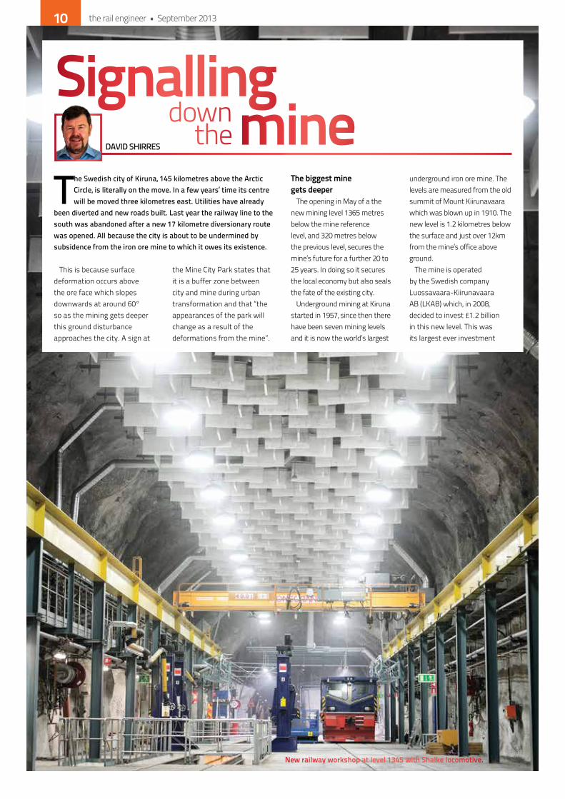
(cover image)new railway workshop at level 1345 with shalke locomotive.
Contents14
32
52
60
Many sites atLiverpool StreetThe new Crossrail Station
Safety rules, rule!Life Saving Rules by Gareth Llewellyn
National Track Plant Exhibition Review
Highland Communications
the rail engineer • September 2013 3
We’re looking to highlight the latest projects and innovations in
Plant and Equipment Concretein the November Issue of the rail engineer.
Got a fantastic innovation? Working on a great project? Call Nigel on 01530 56 57 00 NOW!

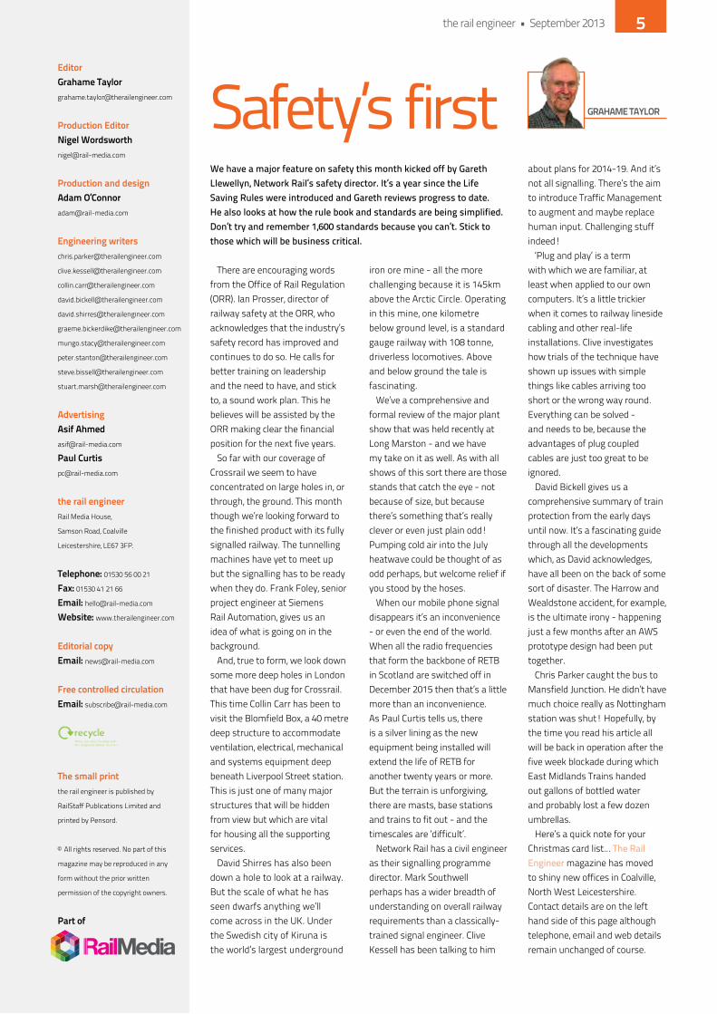
We have a major feature on safety this month kicked off by Gareth Llewellyn, Network Rail’s safety director. It’s a year since the Life Saving Rules were introduced and Gareth reviews progress to date. He also looks at how the rule book and standards are being simplified. Don’t try and remember 1,600 standards because you can’t. Stick to those which will be business critical.
There are encouraging words from the office of Rail Regulation (oRR). ian Prosser, director of railway safety at the oRR, who acknowledges that the industry’s safety record has improved and continues to do so. he calls for better training on leadership and the need to have, and stick to, a sound work plan. This he believes will be assisted by the oRR making clear the financial position for the next five years.
So far with our coverage of Crossrail we seem to have concentrated on large holes in, or through, the ground. This month though we’re looking forward to the finished product with its fully signalled railway. The tunnelling machines have yet to meet up but the signalling has to be ready when they do. Frank Foley, senior project engineer at Siemens Rail Automation, gives us an idea of what is going on in the background.
And, true to form, we look down some more deep holes in London that have been dug for Crossrail. This time Collin Carr has been to visit the Blomfield Box, a 40 metre deep structure to accommodate ventilation, electrical, mechanical and systems equipment deep beneath Liverpool Street station. This is just one of many major structures that will be hidden from view but which are vital for housing all the supporting services.
david Shirres has also been down a hole to look at a railway. But the scale of what he has seen dwarfs anything we’ll come across in the Uk. Under the Swedish city of kiruna is the world’s largest underground
iron ore mine - all the more challenging because it is 145km above the Arctic Circle. operating in this mine, one kilometre below ground level, is a standard gauge railway with 108 tonne, driverless locomotives. Above and below ground the tale is fascinating.
We’ve a comprehensive and formal review of the major plant show that was held recently at Long Marston - and we have my take on it as well. As with all shows of this sort there are those stands that catch the eye - not because of size, but because there’s something that’s really clever or even just plain odd! Pumping cold air into the July heatwave could be thought of as odd perhaps, but welcome relief if you stood by the hoses.
When our mobile phone signal disappears it’s an inconvenience - or even the end of the world. When all the radio frequencies that form the backbone of ReTB in Scotland are switched off in december 2015 then that’s a little more than an inconvenience. As Paul Curtis tells us, there is a silver lining as the new equipment being installed will extend the life of ReTB for another twenty years or more. But the terrain is unforgiving, there are masts, base stations and trains to fit out - and the timescales are ‘difficult’.
network Rail has a civil engineer as their signalling programme director. Mark Southwell perhaps has a wider breadth of understanding on overall railway requirements than a classically-trained signal engineer. Clive kessell has been talking to him
about plans for 2014-19. And it’s not all signalling. There’s the aim to introduce Traffic Management to augment and maybe replace human input. Challenging stuff indeed!
‘Plug and play’ is a term with which we are familiar, at least when applied to our own computers. it’s a little trickier when it comes to railway lineside cabling and other real-life installations. Clive investigates how trials of the technique have shown up issues with simple things like cables arriving too short or the wrong way round. everything can be solved - and needs to be, because the advantages of plug coupled cables are just too great to be ignored.
david Bickell gives us a comprehensive summary of train protection from the early days until now. it’s a fascinating guide through all the developments which, as david acknowledges, have all been on the back of some sort of disaster. The harrow and Wealdstone accident, for example, is the ultimate irony - happening just a few months after an AWS prototype design had been put together.
Chris Parker caught the bus to Mansfield Junction. he didn’t have much choice really as nottingham station was shut! hopefully, by the time you read his article all will be back in operation after the five week blockade during which east Midlands Trains handed out gallons of bottled water and probably lost a few dozen umbrellas.
here’s a quick note for your Christmas card list... The Rail Engineer magazine has moved to shiny new offices in Coalville, north West Leicestershire. Contact details are on the left hand side of this page although telephone, email and web details remain unchanged of course.
Safety’s firsteditorgrahame [email protected]
Production editornigel [email protected]
Production and designadam o’[email protected]
engineering [email protected]
advertisingasif [email protected]
Paul [email protected]
the rail engineerRail Media house,
Samson Road, Coalville
Leicestershire, Le67 3FP.
telephone: 01530 56 00 21
Fax: 01530 41 21 66
email: [email protected]
Website: www.therailengineer.com
editorial copyemail: [email protected]
Free controlled circulationemail: [email protected]
the small printthe rail engineer is published by
RailStaff Publications Limited and
printed by Pensord.
© All rights reserved. no part of this
magazine may be reproduced in any
form without the prior written
permission of the copyright owners.
Part of
graHame taylor
the rail engineer • September 2013 5

Construction of the Liefkenshoek railway link, the new direct freight link between the left and right banks of Antwerp in Belgium, is well underway and running to plan.
The newly-constructed twin tunnels under the Scheldt River and kanaaldok are about six kilometres long, which makes them the longest rail tunnels in
Belgium.it is also the biggest railway
construction site in the country, with hundreds of people working there at peak times.
Financing, design, construction and maintenance is being undertaken by a PPP contract with Locorail, a joint venture of BAM PPP, CFe and Vinci Concessions. The 16.2 kilometre, double-track rail link consists of 4.8 kilometres of embankment, 4.2 kilometres of open and
covered trench, 1.2 kilometres of existing tunnel (reopening of the already built but never used Beveren rail tunnel) and almost six kilometres of double-bored tunnel with an internal diameter of 7.3 metres.
Tunnel construction works started in november 2008 and have just been largely completed although some work is still going on in the right hand bank. Meanwhile, Belgian rail infrastructure manager infrabel started laying the tracks and installing the signal system and overhead lines on the section between the South yard and the Beveren rail tunnel last year.
Plans are to commence testing next spring with the new route coming into service in September 2014.
Longest rail tunnels in Belgium
Network Rail is not only affected by its own earthwork problems. The Hatfield Stainforth landslip started in a colliery adjacent to the line. Now another neighbour, this one next to the tunnel portal at Chipping Camden in the Cotswolds, is causing trouble.
The land, which is privately owned and measures around 14,000m², has moved by nearly a metre in the last eight weeks and has created a scar in the cutting five metres high, posing a risk to the safe operation of the railway. To temporarily mitigate the risk, all the lineside equipment has been diverted and a stringent monitoring regime put in place.
Mike Gallop, route asset management director, network Rail Western, said: “We need to stabilise the cutting immediately to protect the railway, otherwise we could risk the line being shut
from a potential land slip.”Approximately 80,000 tonnes of
earth will be removed from the cutting to create a safe gradient that will prevent the land from moving, thus stabilising the cutting for the long-term. As part of this work, all the trees on the affected land will be removed but network Rail plans to work closely with the landowner, harrowby estates, and the local authorities to replant the land with native tree species that are in keeping with the appearance of this Area of outstanding natural Beauty.
More earthwork woes
Stadler Pankow, the Berlin-based member of the Swiss Stadler group, has received an order for four additional Variobahn trams from London Tramlink. The five-segment trams are 32 metres long and 2.65 metres wide. They have low floors throughout, at a maximum level of 385mm, making the trams easier to board. They have 72 seats and standing room for 134 passengers, can reach a maximum speed of 80 km/h, and are fully air conditioned.
The new trams will be delivered in 2015. They are part of an option on the original order for six vehicles which have been in operation in the London Borough of Croydon since spring 2012.
The Stadler Variobahn is a proven design. First developed 20 years ago by ABB henschel, which became part of Adtranz, variants are now in regular use in Bochum, Bergen, Mannheim, Potsdam, helsinki and Sydney. The fleet has now covered 90 million miles and the experience gained allows Stadler to offer a product with short maintenance intervals, high passenger comfort, sustainability, flexibility and reliability.
Michael daum, director of Stadler Pankow Gmbh, explains: “We are delighted with the high level of satisfaction with the Variobahn. The four additional trams will be built at our factories in Berlin before being transported to London.”
More new trams
neWSPh
oTo:
TUC
RAi
L
the rail engineer • September 20136
How do you connect speed and sustainability?
Think Murphy.
Breathing life into infrastructure
For deeper thinking visit www.murphygroup.co.uk
Electrification is the future of rail infrastructure, linking passengerswith faster journey times and a reduced environmental impact. It’s a task which will demand prodigious levels of teamwork and first-class commitment to safe practices. Murphy has animpressive track record of working collaboratively and safely as principal contractor and we’ve won multiple safety awards,including Network Rail’s Partnership Award for Safety. Ourspecialist engineering capability is well recognised for itsinnovative approach to the delivery of complex civil engineering
projects such as upgrading the UK’s Railways to accommodate for the National Electrification Programme.
For more than 60 years, Murphy has been building andmaintaining the infrastructure of the nation. We continue to break new ground with high-profile projects across a range of key industries. From national tunnelling, power and rail projects to major water and wastewater contracts and process plantconstruction; with Murphy, the thinking is always as important as the delivery.

The countdown is on to the opening of the new square at King’s Cross, and the end of the King’s Cross station reconstruction project, due at the end of September.
The new Western Concourse was opened before last year’s olympics. during the Games the entire station was open, and then immediately afterwards the old ‘temporary’ southern concourse was closed for demolition. in its
place will be king’s Cross Square, a new 75,000 sq feet space that will give passengers and people in the area improved entrances to the London Underground, an area dedicated to public art, a stunning lighting scheme and double the
number of trees. Boris Johnson, Mayor of London,
and Sir david higgins, network Rail’s chief executive, marked the 50-day countdown by touring the site where J. Murphy & Sons Limited is currently working on the final phase of civil engineering works to complete king’s Cross Square. They then laid one of the final paving stones on the new square.
Boris Johnson commented
afterwards: “The incredible regeneration of king’s Cross continues apace. network Rail is renovating this historic location with ingenuity and flair and this wonderful new square will be the perfect gateway to almost 70 acres of new public spaces, businesses and homes for Londoners, setting a new standard that we should aspire to for all future station redevelopment.”
The countdown to King’s Cross Square
neWS
Plans have been revealed to build a battery powered train for testing on the British network. This could see trains running on battery power over non-electrified lines, before charging at terminal stations, or using their batteries to run over diesel lines in otherwise electrified parts of the railway.
Funding is coming from network Rail, the enabling innovation Team (hosted by the Rail Safety and Standards Board) and the department for Transport. network Rail will be working closely with derby-based train manufacturer Bombardier and operator Greater Anglia, and the project will use one of the operator’s Class 379s as a test-bed to determine future battery requirements and what kind of train might be needed.
This train will be adapted by Bombardier and fitted with two different forms of batteries: lithium (iron magnesium) phosphate and hot sodium nickel salt. The batteries will undergo many lab tests before being fitted to the train.
Bombardier said: “We are very
enthusiastic to be collaborating in this ground breaking project with network Rail. This project is an innovative development to provide an integrated battery system as a power source for the well proven electrostar train.”
The modified 379 will then undergo a variety of tests, some on the old dalby test track. Should those tests be successful, the train will then run on an electrified branch line on the Anglia route with its pantograph down. This is so that if there is a problem, it can raise its pantograph, and collect power again. This running will be both in and out of passenger service.
once the programme is complete, by the end of 2014, the unit will be returned to its former state and will run as a normal unit again in service.
Battery powered trains for East Anglia
www.moore-concrete.com
Bridge Deck Construction
Station PlatformsViaduct SlabsBespoke Units
STRUCTURAL PRECASTFOR RAILWAYS
MOORE CONCRETE PRODUCTS LTDCaherty House, 41 Woodside Rd,
Ballymena BT42 4QH N.I. T. 028 2565 2566F. 028 2565 8480 E. [email protected]
the rail engineer • September 20138
neWS
personal devices and provide the up to date information that passengers want.
Many of these technologies bring social benefits such as reducing carbon foot print and also benefit from sound economic business cases for instance by reducing fuel use, improving safety, or by providing advertising revenue streams.
The ability to support a multiplicity of systems on train is now all the easier by utilising a common ethernet connection between equipment, ensuring installation costs are minimised through installation during a single period of downtime.
The need to keep rolling stock in continued service means that investment in rolling stock assets is essential to ensure that they are up to date, meet passenger expectation and are sought
after by train operators. These initiatives make it all the more timely to take the opportunity to overlay maintenance and refurbishment with vehicle enhancement programmes.
At RVe 2013 you can meet the experts from many leading companies including Brentto industry, Creactive design, dC Airco, icomera, infodev, Televic, the event organisers onyxrail and many more. The event for 2013 is supported by the Rail Alliance and Rail Media Group. RVe 2013 will be bigger, broader and better than RVe2012. exhibition space is going fast and visitors to this free event can be assured of a rewarding visit so put RVe derby on Thursday 3 october in your diary and we will look forward to welcoming you.
register online now at:www.rve2013.co.uk
Imagine if your passengers could see how full each carriage of an approaching train is, real time on their smartphone. Imagine if you could view live CCTV images in an off-train facility, send text or RSS based bulletins directly to information screens on the train, provide location based advertising or advise your drivers of the optimal speed to improve punctuality and minimise energy usage.
Whilst it sounds futuristic ,all of these technologies are available today and can be installed retrospectively to existing rail assets.
often, uplifts are driven by the need to be innovative in the franchise bidding process, or to look more deeply into how assets can remain not only leasable but of increased value to operators whilst delivering real benefits to the passenger or the operator.
Passengers want a good travelling experience, to be well informed and to travel in cool carriages. They also expect value for money within the ticket price. These demands provide challenges to operators balancing service and cost.
Modern interior design incorporating the best materials, colourways and solutions can significantly lift the interior ambience of older trains and Led lighting can provide consistent low energy lighting or provide mood lighting lasting for the residual life of the train.
Passengers expect to be safe when travelling and the latest CCTV systems enable timely intervention to intercept the perpetrators of crime not just to bring them to justice afterward. entertainment content servers coupled with WiFi services can enable content streaming to
Technology, Materials, Design!Rail Vehicle Enchancements 2013 is far more than just a trade show
the rail engineer • September 2013 9
The Swedish city of Kiruna, 145 kilometres above the Arctic Circle, is literally on the move. In a few years’ time its centre will be moved three kilometres east. Utilities have already
been diverted and new roads built. Last year the railway line to the south was abandoned after a new 17 kilometre diversionary route was opened. All because the city is about to be undermined by subsidence from the iron ore mine to which it owes its existence.
This is because surface deformation occurs above the ore face which slopes downwards at around 60° so as the mining gets deeper this ground disturbance approaches the city. A sign at
the Mine City Park states that it is a buffer zone between city and mine during urban transformation and that “the appearances of the park will change as a result of the deformations from the mine”.
the biggest mine gets deeper
The opening in May of a the new mining level 1365 metres below the mine reference level, and 320 metres below the previous level, secures the mine’s future for a further 20 to 25 years. in doing so it secures the local economy but also seals the fate of the existing city.
Underground mining at kiruna started in 1957, since then there have been seven mining levels and it is now the world’s largest
underground iron ore mine. The levels are measured from the old summit of Mount kiirunavaara which was blown up in 1910. The new level is 1.2 kilometres below the surface and just over 12km from the mine’s office above ground.
The mine is operated by the Swedish company Luossavaara-kiirunavaara AB (LkAB) which, in 2008, decided to invest £1.2 billion in this new level. This was its largest ever investment
Signallingminedown
theDAVID SHIRRES
new railway workshop at level 1345 with shalke locomotive.
the rail engineer • September 201310
and required the removal of 4.3 million cubic metres of rock and the construction of 87 kilometres of new tunnels. When fully operational in 2017, it will be able to produce 35 million tonnes (Mt) per annum. This is done by depositing ore from night-time blasting operations into loading chutes for transport to a crushing plant that evenly grades for hoisting to the surface.
The ore is lifted a total of 1.4 kilometres in two stages at 17 metres per second in skips that carry 34 tonnes. People and equipment, however, do not descend in mine shafts. instead they are transported in vehicles that take around 20 minutes to drive down the mine’s 10° slopeways.
rails above and below the surface
Since iron ore mining started in 1890, almost a billion tonnes of ore has been extracted. however, large scale mining operations required the opening of the railway to Lulea, on the Baltic, in 1899. in 1903, this line was extended to the ice-free port of narvik in norway. Clearly this railway is essential to the mine. What is not so visible is the railway network down the mine which is also an essential part of the mine’s production process.
When fully operational, the new mine level will have ten loading chute galleries for newly extracted ore, and one kilometre away in stable rock, four crushing plants. Speaking to The Rail Engineer, hans engberg, LkAB’s project manager for the new level, explained that a detailed study had shown that a railway was the most cost effective way to transport ore underground as it offered a high degree of automation and, unlike conveyors, can handle unevenly-graded extracted ore.
the underground networkThus the new mining level has
a rail network to transport ore between loading chutes and crushing plants. Loading chutes drop ore into the wagons. during
unloading the entire train is supported on rollers as the full-size wagon bottom doors open to dump around 700 tonnes of ore into the crusher in two and a half minutes. To maximise capacity and minimise spillage the new level is a standard gauge (1435 mm) railway compared with the 891 mm gauge railway on the 1045 metre level above.
When fully operational in 2017, there will be a 15 kilometre network with ten loading chute galleries and four crushing plants with a daily haulage capacity of 140,000 tonnes per day. however the mine’s seven trains will carry a typical total of 100,000 tonnes a day in 125 train movements. Currently two trains operate on a 12 kilometre network which connects three loading chutes, one crusher and the workshop.
each train consists of 21 unbraked wagons and carries between 600 and 800 tonnes of ore. The locomotives produced by Shalke are 108-tonne Bo-Bo locomotives. They have four 225 kW AC traction motors powered from an overhead 750 volt dC supply or their own batteries and have a maximum speed of 25 km per hour.
cbtc underground hans engberg explains that
kiruna’s underground mine has to compete with open cast mines on the quality of its ore and efficient mining operations. hence the underground railway has to be fully automated leading to the selection of Bombardier’s inTeRFLo 150 system to control the mine’s driverless trains. This is a Communications Based Train Control (CBTC) system which maximises throughput by variable moving blocks.
The inTeRFLo 150 system provides safety through automatic train protection (ATP) and traffic automation through automatic train operation (ATo). The ATP ensures adherence to the railway
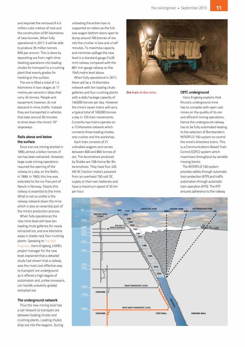
0m
142m
230m275m320m
420m
540m
740m775m
1045m
1175m
1365m
1900 19101920
19301940
1950
1960
19651970
1980
1990
2000
2005
LANDSLIDE ZONE FISSURE ZONE DEFORMATION ZONE
ORE REFININGPLANT
RAILWAY TONARVIK (NORWAY)
MAIN TRANSPORT LEVEL
CRUSHING
CRUSHING FOOT WALL HANGING WALL
NEW MAIN TRANSPORT LEVEL
ORE BODY
ore train in the mine.
the rail engineer • September 2013 11
speed profile and provides safe train separation and junction control. The ATo is an automatic driver that commands the locomotive to drive according to given authorities and perform precision stops where needed.
Train location is determined from tagged balises and axle-driven tachometers. A traffic control centre (TCC) provides centralised traffic control, manages the interlocking and a radio block centre for train communication, issuing movement authorities to the train.
inTeRFLo 150 is suitable for both regional and industrial lines. in 1999 it was first used in
Chile’s el Teniente mine. it works in the same way as the CiTyFLo 650 system to be installed on London Underground’s (LU) Sub Surface lines as described in issue 102 of The Rail Engineer (April 2013) but is adapted for mining operations with automatic route setting, derailment detection, integration with loading and unloading systems, and compatibility with whatever radio system is used in the mine. The kiruna installation includes 57 point machines and 180 balises. Bombardier is also supplying on-board ATo and ATP equipment for nine production and four service locomotives.
The head of industrial mining for Bombardier Rail Control Solutions, Valentine Paramasivam, considers that there is great potential for increased use of automated railways in mines. To this end, Bombardier have partnering agreements with companies such as ABB, Schalke, Midroc Automation and nordic Mining Technology to further exploit this market. As an example they were recently awarded a train control systems contract for the Grasberg copper and gold mine on Papua, indonesia, 2,700 metres above sea level, which will have a 28 kilometre rail network.
the iron ore linekiruna’s mine currently has
a licence to extract 30 Mt per annum, 37% of which is waste. iron ore waste is good aggregate material but is too expensive to transport. on the surface a processing plant produces iron ore products, mainly pellets. kiruna and adjacent mines produce 27 Mt of such products for dispatch by rail to the ports of Lulea on the Baltic or narvik in norway which, being ice-free all year, takes 60% of this traffic.
The 473 kilometre Lulea to narvik railway is single track line and electrified at 15kV 162/3 hz AC. Trains travelling the 170 kilometres from kiruna to narvik first descend to Lake Torneträsk at 400 metres before climbing at a 1 in 91 gradient to reach the 523 metre summit on the Swedish / norwegian border. The railway then clings to the side of a fjord as it descends to narvik, 42 kilometres away with a maximum gradient of 1 in 60. At 68° north this is the most northerly point of the european rail network.
Since 1995, the line has been operated by Malmtrafik (MTAB), a subsidiary of LkAB. in 2007 it was upgraded to increase the axle load limit from 25 to 30 tonnes and passing loops
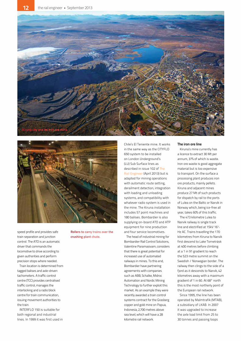
rollers to carry trains over the crushing plant chute.
Kiruna city and its iron ore mine.
the rail engineer • September 201312
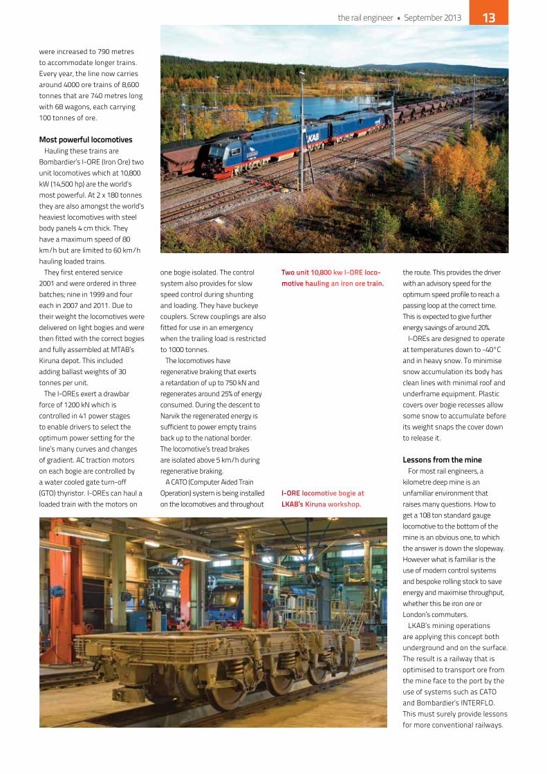
were increased to 790 metres to accommodate longer trains. every year, the line now carries around 4000 ore trains of 8,600 tonnes that are 740 metres long with 68 wagons, each carrying 100 tonnes of ore.
most powerful locomotiveshauling these trains are
Bombardier’s i-oRe (iron ore) two unit locomotives which at 10,800 kW (14,500 hp) are the world’s most powerful. At 2 x 180 tonnes they are also amongst the world’s heaviest locomotives with steel body panels 4 cm thick. They have a maximum speed of 80 km/h but are limited to 60 km/h hauling loaded trains.
They first entered service 2001 and were ordered in three batches; nine in 1999 and four each in 2007 and 2011. due to their weight the locomotives were delivered on light bogies and were then fitted with the correct bogies and fully assembled at MTAB’s kiruna depot. This included adding ballast weights of 30 tonnes per unit.
The i-oRes exert a drawbar force of 1200 kn which is controlled in 41 power stages to enable drivers to select the optimum power setting for the line’s many curves and changes of gradient. AC traction motors on each bogie are controlled by a water cooled gate turn-off (GTo) thyristor. i-oRes can haul a loaded train with the motors on
one bogie isolated. The control system also provides for slow speed control during shunting and loading. They have buckeye couplers. Screw couplings are also fitted for use in an emergency when the trailing load is restricted to 1000 tonnes.
The locomotives have regenerative braking that exerts a retardation of up to 750 kn and regenerates around 25% of energy consumed. during the descent to narvik the regenerated energy is sufficient to power empty trains back up to the national border. The locomotive’s tread brakes are isolated above 5 km/h during regenerative braking.
A CATo (Computer Aided Train operation) system is being installed on the locomotives and throughout
the route. This provides the driver with an advisory speed for the optimum speed profile to reach a passing loop at the correct time. This is expected to give further energy savings of around 20%.
i-oRes are designed to operate at temperatures down to -40°C and in heavy snow. To minimise snow accumulation its body has clean lines with minimal roof and underframe equipment. Plastic covers over bogie recesses allow some snow to accumulate before its weight snaps the cover down to release it.
lessons from the mineFor most rail engineers, a
kilometre deep mine is an unfamiliar environment that raises many questions. how to get a 108 ton standard gauge locomotive to the bottom of the mine is an obvious one, to which the answer is down the slopeway. however what is familiar is the use of modern control systems and bespoke rolling stock to save energy and maximise throughput, whether this be iron ore or London’s commuters.
LkAB’s mining operations are applying this concept both underground and on the surface. The result is a railway that is optimised to transport ore from the mine face to the port by the use of systems such as CATo and Bombardier’s inTeRFLo. This must surely provide lessons for more conventional railways.
two unit 10,800 kw i-ore loco-motive hauling an iron ore train.
i-ore locomotive bogie at lKab’s Kiruna workshop.
the rail engineer • September 2013 13

The £14.8 billion Crossrail project is now progressing at a pace. The route from Maidenhead and Heathrow in the West to Shenfield and Abbey Wood in the East will run through 21km
of twin-bore tunnels up to 40 metres below the ground. More plans have recently been submitted for a new station at Abbey Wood and for property development at Farringdon. There is now even a short list of bidders competing for the privilege of running the prestigious Crossrail service when all the work is completed in 2018.
The new route will pass through 37 stations. A number of these are currently experiencing huge change involving complex engineering challenges, usually in very confined conditions.
Liverpool Street is a good example of this. The new Crossrail station will be located between the existing Liverpool Street and Moorgate stations. The programme of building work includes two new entrances and ticket halls, creating new interchanges with the northern, Central, Metropolitan, Circle and hammersmith & City lines, as well as connections to Stansted Airport and national Rail Services. The Rail Engineer recently visited the site to see how this complex project is progressing.
tbm break throughin 2012, tunnel boring machines
(TBMs) elizabeth and Victoria started to work their way toward Liverpool Street station from Limmo Peninsula to the east of Canary Wharf. They are now working westward, creating new tunnels that will eventually approach the Liverpool Street station site, and will break through into the pre-constructed underground tunnels that are currently being built to accommodate the platforms within the Crossrail station.
There, the TBMs will undergo any essential planned maintenance before moving on, breaking out of the station tunnel to complete the 8.3km twin-bore tunnels to Farringdon east. The TBMs are expected to
pass through the Liverpool Street station site in the autumn 2014.
Much of the work currently taking place is in preparation for the passage of elizabeth and Victoria through the site. Troy easthorpe is Crossrail’s project manager for Liverpool Street station and Colin niccolls is project manager for the station tunnelling work. Troy explained that the Liverpool Street Crossrail station is currently divided up into four main sites.
Many sites at
COLIN CARR
Liverpool Street
tbm elizabeth being lowered into place october 2012.
the rail engineer • September 201314
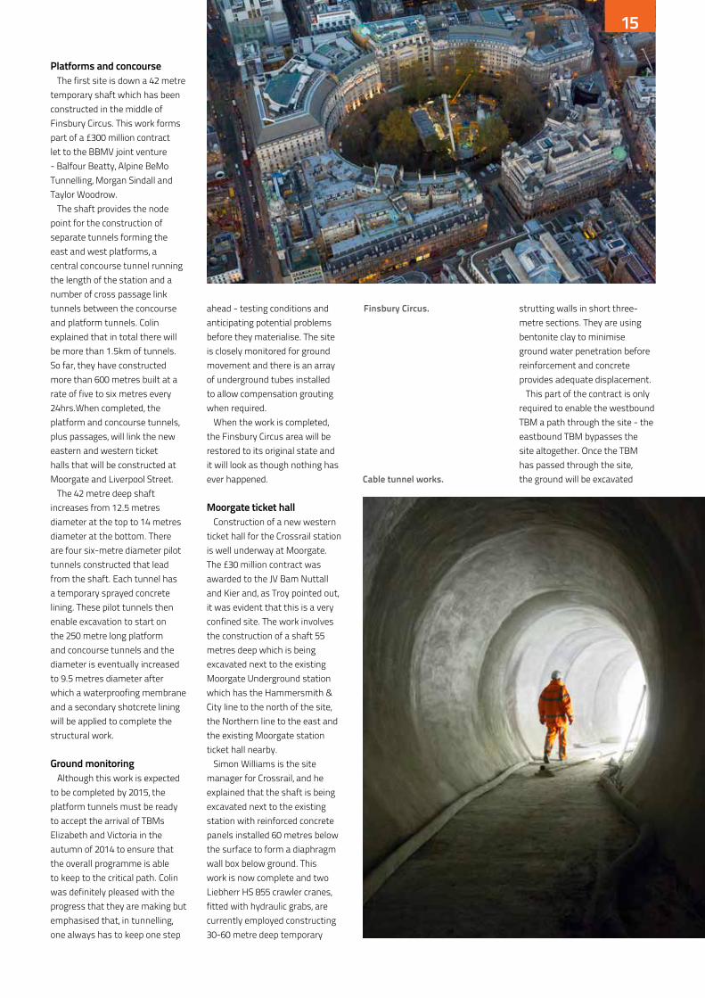
Platforms and concourseThe first site is down a 42 metre
temporary shaft which has been constructed in the middle of Finsbury Circus. This work forms part of a £300 million contract let to the BBMV joint venture - Balfour Beatty, Alpine BeMo Tunnelling, Morgan Sindall and Taylor Woodrow.
The shaft provides the node point for the construction of separate tunnels forming the east and west platforms, a central concourse tunnel running the length of the station and a number of cross passage link tunnels between the concourse and platform tunnels. Colin explained that in total there will be more than 1.5km of tunnels. So far, they have constructed more than 600 metres built at a rate of five to six metres every 24hrs.When completed, the platform and concourse tunnels, plus passages, will link the new eastern and western ticket halls that will be constructed at Moorgate and Liverpool Street.
The 42 metre deep shaft increases from 12.5 metres diameter at the top to 14 metres diameter at the bottom. There are four six-metre diameter pilot tunnels constructed that lead from the shaft. each tunnel has a temporary sprayed concrete lining. These pilot tunnels then enable excavation to start on the 250 metre long platform and concourse tunnels and the diameter is eventually increased to 9.5 metres diameter after which a waterproofing membrane and a secondary shotcrete lining will be applied to complete the structural work.
ground monitoringAlthough this work is expected
to be completed by 2015, the platform tunnels must be ready to accept the arrival of TBMs elizabeth and Victoria in the autumn of 2014 to ensure that the overall programme is able to keep to the critical path. Colin was definitely pleased with the progress that they are making but emphasised that, in tunnelling, one always has to keep one step
ahead - testing conditions and anticipating potential problems before they materialise. The site is closely monitored for ground movement and there is an array of underground tubes installed to allow compensation grouting when required.
When the work is completed, the Finsbury Circus area will be restored to its original state and it will look as though nothing has ever happened.
moorgate ticket hallConstruction of a new western
ticket hall for the Crossrail station is well underway at Moorgate. The £30 million contract was awarded to the JV Bam nuttall and kier and, as Troy pointed out, it was evident that this is a very confined site. The work involves the construction of a shaft 55 metres deep which is being excavated next to the existing Moorgate Underground station which has the hammersmith & City line to the north of the site, the northern line to the east and the existing Moorgate station ticket hall nearby.
Simon Williams is the site manager for Crossrail, and he explained that the shaft is being excavated next to the existing station with reinforced concrete panels installed 60 metres below the surface to form a diaphragm wall box below ground. This work is now complete and two Liebherr hS 855 crawler cranes, fitted with hydraulic grabs, are currently employed constructing 30-60 metre deep temporary
strutting walls in short three-metre sections. They are using bentonite clay to minimise ground water penetration before reinforcement and concrete provides adequate displacement.
This part of the contract is only required to enable the westbound TBM a path through the site - the eastbound TBM bypasses the site altogether. once the TBM has passed through the site, the ground will be excavated
Finsbury circus.
cable tunnel works.
the rail engineer • September 2013 15
down to the required level and the strutting walls will be demolished. All the spoil will then be carted off to Wallasea island to form a bird sanctuary, along with 4.5 million tonnes of spoil from other Crossrail sites. Following this and some more additional piling to stabilise the site, work on the new ticket hall will commence.
as deep as nelson’s columnAlso part of the Liverpool
Street station site is the Blomfield Box - a 40 metre deep structure to accommodate ventilation, electrical, mechanical and systems equipment for the new Crossrail station. it is part of a £130 million contract awarded to Laing o’Rourke which is also responsible for the construction of both stations and the platforms and central access passageways. Chris Goatman is the site manager for Crossrail and Malcolm nelson the project director for Laing o’Rourke.
This is another incredibly cramped site situated alongside the Broadgate development. Chris explained that they had already driven sixty-seven 1.2 metre diameter reinforced concrete piles to form a perimeter box. in addition, they are in the process of driving a further fifteen 1.5 metre diameter piles to support the floor slab when the excavation is completed. This
will stop the box from floating, a distinct possibility due to potential ground water pressure even though the box weighs 10,000 tonnes!
Malcolm was also keen to point out that the box will be deep enough to comfortably house a column dedicated to his namesake.
More 300mm reinforced concrete piles have been driven around the site to protect the adjacent existing buildings and ensure that all is stable so that neighbours will not be affected by the work. Troy pointed out that Crossrail devotes a considerable amount of time to its neighbours, keeping them informed about progress, new work, possible road closures and progress of the TBMs.
he also indicated that so far there have been no delays to train services or impact on local communities even though, at this particular location, they are constructing a box formed from the deepest pile shaft with 40m long piles, containing 22 tonne reinforcement cages, that have been constructed less than three metres away from live London Underground running lines. it is something that he and his team are clearly very proud of and with some justification.
So far, over 250 piles have been completed including all high-level foundation works and two thirds of the main shaft piles installed up to 50 metres deep, making
the box Crossrail’s deepest piled shaft. The main shaft piling is now almost complete.
utilities, systems & equipmentAdjacent to the box, a new
Communications equipment Room (CeR), power substation and switch rooms for the Liverpool Street London Underground station are being constructed as part of a £23 million contract awarded to Taylor Woodrow. This will allow the demolition of the existing substation to create space for the Broadgate ticket hall on Liverpool Street. The power substation and switch rooms are due to be completed later this year.
other works include a new 53-metre-long cable tunnel which has now been completed five metres below the ground and it is connected to the new substation. it is the first permanent sprayed concrete lining tunnel to be finished on the Crossrail project.
broadgateThe fourth site is at Liverpool
Street which will house the Broadgate ticket hall. Prior to Laing o’Rourke constructing the new sub-surface ticket hall, Taylor Woodrow is busy clearing the area by diverting all of the existing services around the site or through a new purpose-built utility corridor at the southern most part of the site. This will allow Laing o’Rourke to
commence piling work for the new station in 2014.
When completed, the new ticket hall will provide step-free access from street level to the new Crossrail platforms. A subsurface ticket hall will be constructed to link into the existing London Underground one at Liverpool Street.
Well managed siteit was a fascinating, whistle
stop tour. At each location, the discipline and attitude to safety was commendable. every site appeared to be well managed and every manager was clearly aware of the importance of their site in the overall scheme of things.
As the heavy engineering work is completed and elizabeth and Victoria start to eat up ground west of the station, Laing o’Rourke will slowly take over each site to construct the station fittings and furnishings ready for the opening of the Crossrail service in 2018.
everything indicates that this will happen according to plan and the end result will be very impressive, even though many people using these facilities will not have a clue about the real engineering work that is taking place today to provide this service tomorrow.
Those working on these sites today will certainly remember and they should feel very proud of what they have achieved.
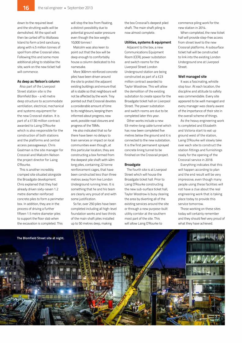
the blomfield street site at night.
the rail engineer • September 201316

wh
yat
ten
d?
HS2: the wider network, the wider bene�ts
industry leaders group
Think Tank, Birmingham Science Museum, Curzon Street, birmingham, b4 7xg.
Thursday 19 September 2013
On September 19th, at Curzon Street Birmingham, Greengauge 21 is holding the one must-attend conference on HS2 for 2013. At this crucial stage, we are taking the opportunity to answer the key questions that still surround HS2.
Our aim for the day is simple: to transform any lingering perception that HS2 is of limited, narrow bene t. It isn’t: its bene cial effects extend right across the national rail network. Its impact on the economies of all of the cities and regions it serves will be highly bene cial – both locally, and ultimately, to the national economy and exchequer.
On the day, we will be showcasing Network Rail’s new research into HS2’s impacts on the wider network, presenting ndings for the rst time in a public arena.
We will learn from HS2 Ltd about the new results from its leading edge work examining how the project will impact on city and regional economies, moving beyond the con nes of traditional transport bene t cost appraisal. Again, this will be the rst opportunity to discuss and debate this work in a public arena.
We will hear from a leading independent economist why the north of Britain should be better linked to London and the south east.
The conference is being sponsored by the HSR Industry Leaders Group – a group of private sector businesses that want to see HS2 develop and �ourish.
The day will be attended by key decision makers from both the private and public sectors.
Make sure you are there!
Conference sponsored by:
Conference supported by:
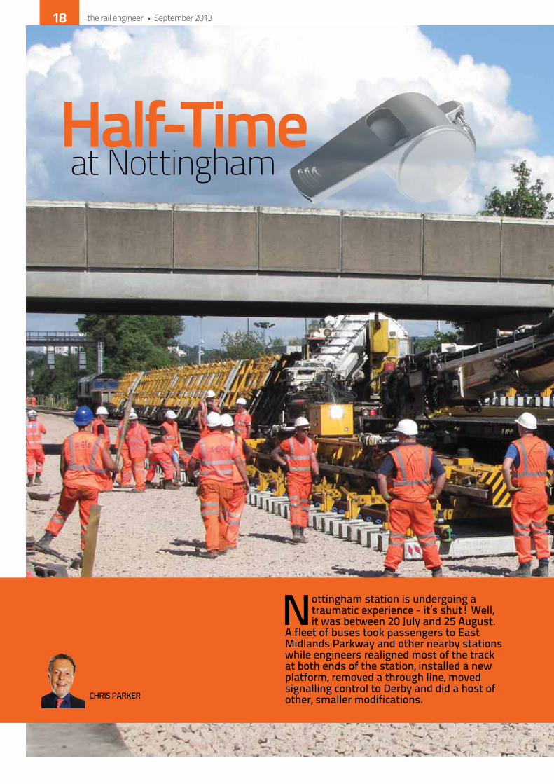
Half-Timeat Nottingham
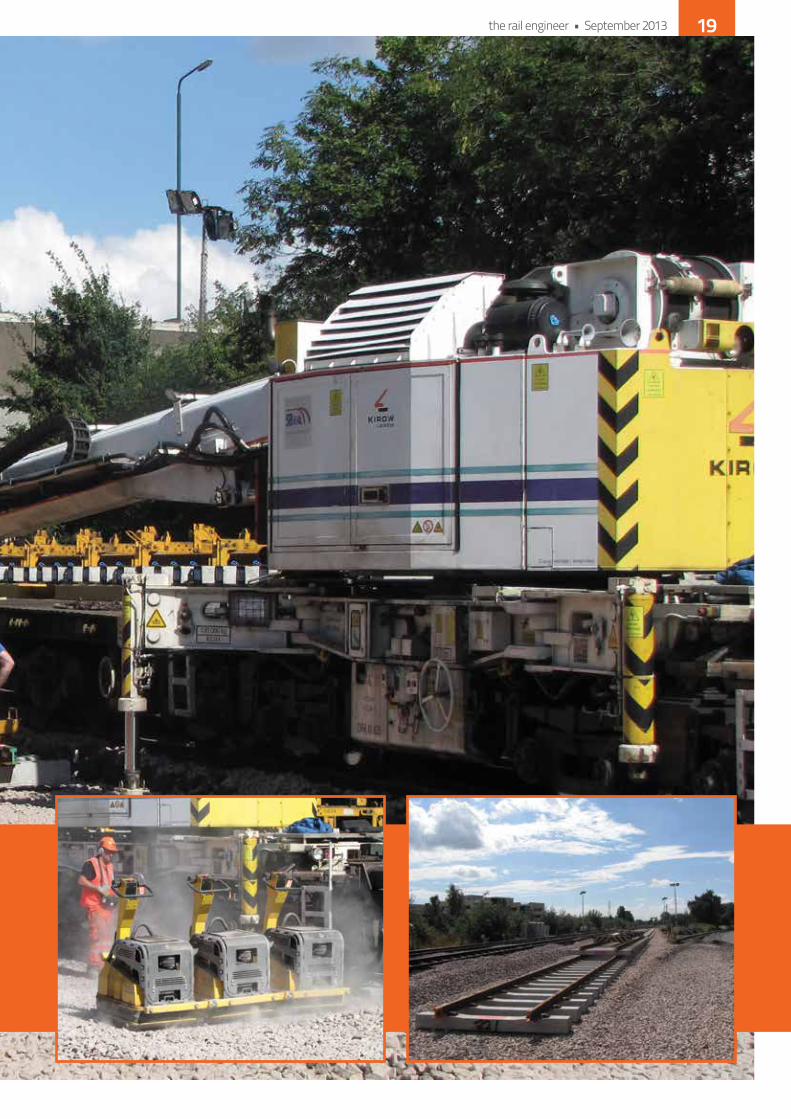
Nottingham station is undergoing a traumatic experience - it’s shut! Well, it was between 20 July and 25 August.
A fleet of buses took passengers to East Midlands Parkway and other nearby stations while engineers realigned most of the track at both ends of the station, installed a new platform, removed a through line, moved signalling control to Derby and did a host of other, smaller modifications.CHRIS PARKER
the rail engineer • September 201318
the rail engineer • September 2013 19
The plans were described in detail only last month but, with such a major piece of work going on, The Rail Engineer couldn’t stay away. So it was off to Mansfield Junction, just west of nottingham station, to see how things were progressing.
two weeks gone - four to goRoughly two weeks into the
nottingham blockade and not only was david horne, managing director of east Midlands Trains (eMT), present to see the work for himself, he was smiling. That was good to see as it meant that things were going well. david’s discussions with network Rail’s senior project manager dave South were also relaxed and amiable - another good sign.
Unsurprisingly, since the relationship between the senior representatives of the two key organisations involved in the project was clearly so good, everything seemed to be going to plan. The interlocking in the east Midlands Control Centre at derby, which was to be up and running at the end of the first weekend, had gone in without delay. As a result, train services as far as Beeston had resumed as planned on Monday morning, 22 July. This arrangement also permitted the running into site from the west of some of the 96 vital engineering trains needed by the works.
At the other side of nottingham station, the service to and from the east, by means of pilot working from Rectory Junction to nottingham and back, was brought into use for a week. it was stopped again by the second weekend of the blockade, to resume on 10 August. This was all as planned from the outset.
The renewal of nottingham West Junction was virtually completed. Mansfield Junction, commenced on 29 July, was well on the way. nottingham east Junction remodelling had started, and the base for the new bay Platform 4 in the station had been laid in.
The other major items completed were the renewal of both Carlton and Colwick level crossings and the permanent closure of Sneinton.
the long and short of itAndy Willetts was on site in his
role as network Rail’s project track asset engineer and was able to give some more details about the S&C being installed by the project. one set of switches had already been laid in at Mansfield Junction. These are exceptional for the project, being F switches, whilst almost all of the 42 other sets of new switches will be ev. The reason for these particularly long switches here is the improvement of the line speed that is being achieved at the junction and around the curve up onto the Mansfield line. The turnout speed
will be 50mph, and this will continue around the curve, whereas the previous speed was only 30mph.
The other exceptions to the general use of ev switches will be in the station area itself. here the speeds will necessarily be low and long switches would be an unnecessary and space wasting feature, so C switches have been specified. in one location, even those are too long to fit the available space, and so special derogation from network Rail standards has been obtained, allowing Bv switches in that case. Andy advised that all of the crossings being installed are welded-in cast ones, and all have been explosive hardened to ensure a long service life.
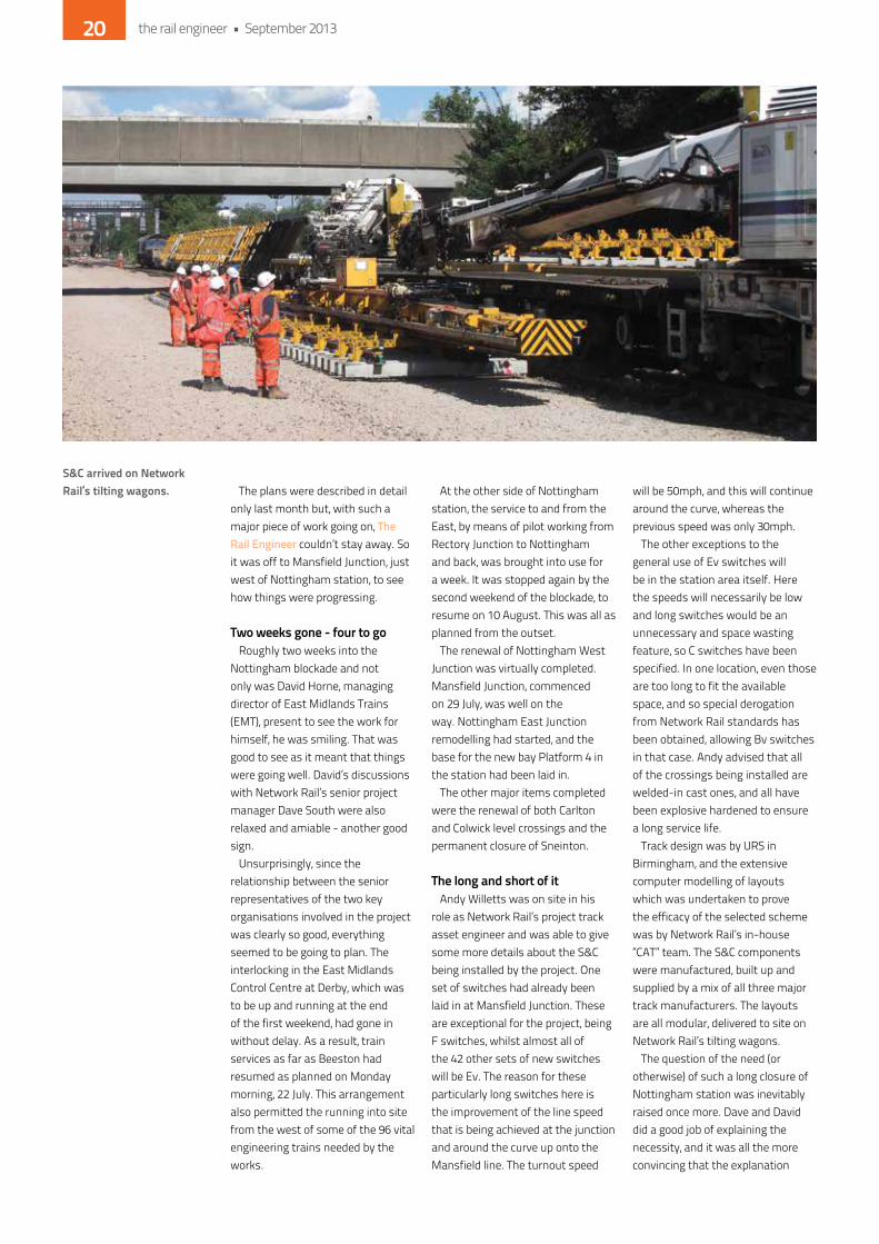
Track design was by URS in Birmingham, and the extensive computer modelling of layouts which was undertaken to prove the efficacy of the selected scheme was by network Rail’s in-house “CAT” team. The S&C components were manufactured, built up and supplied by a mix of all three major track manufacturers. The layouts are all modular, delivered to site on network Rail’s tilting wagons.
The question of the need (or otherwise) of such a long closure of nottingham station was inevitably raised once more. dave and david did a good job of explaining the necessity, and it was all the more convincing that the explanation
s&c arrived on network rail’s tilting wagons.
the rail engineer • September 201320

came from the train operator as well as the project team. The key issues were the very fragile state of the Reed FdM signalling system controlled by Trent Power Box, and the need to lay the new junctions more or less directly back where the old S&C was. The former meant that piecemeal track and signalling renewals were impracticable. The latter meant that new junctions could not be laid in before the old ones were removed and left clipped out of use until the resignalling ‘caught up’.
in conclusion, it was great to see the progress that had been made, and that the network Rail/eMT collaboration over this scheme, which goes back to its very early days in 2007, was still as strong as ever two weeks into the works.
remember the passengersFinally, a little about the practical
arrangements for passengers during the station closure. The site visit to Mansfield Junction started at Beeston, so the logical method of transport was by ‘bus replacement’ from Station Street, nottingham. The organisation was impressive and there were clear signs up everywhere giving the numbers of the bus stops and the destinations served from them. digital displays were also in evidence, presumably ‘borrowed’ from the platforms of the closed station. As in normal
use, some were dedicated to a particular stop, giving departure times for the various services from there. others showed the larger picture, displaying the next service to each principal destination and the number of the stop it would depart from. Very like a real station in fact.
eMT and other operators had staff around on the stops to assist people who couldn’t manage by their own initiative, and there were lots of timetable brochures to hand for those needing them. eMT had even provided branded umbrellas for temporary use in the event of rain (very necessary a few days earlier when there had been torrential thunderstorms) and bottles of mineral water were freely available
(more appropriate to the current hot weather at the time of the visit).
The Beeston bus was already on the stand 15 minutes before it was due away, and would have left on time had the staff not decided, very helpfully, to wait for a woman who needed to buy a ticket before boarding.
The minor delay didn’t trouble the rest of the passengers, and saved the woman a wait in the heat.
The return journey was uneventful too, the facilities provided at the bus stop at Beeston being quite as good relative to the need. overall, it would seem that all concerned have done their very best to make the best of the situation.
the rail engineer • September 2013 21
CLIVE KESSELL
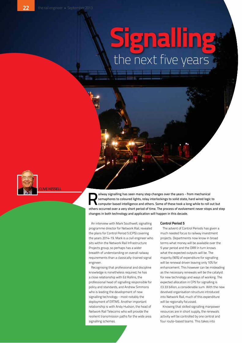
Railway signalling has seen many step changes over the years - from mechanical semaphores to coloured lights, relay interlockings to solid state, hard wired logic to computer based intelligence and others. Some of these took a long while to roll out but
others occurred over a very short period of time. The process of evolvement never stops and step changes in both technology and application will happen in this decade.
An interview with Mark Southwell, signalling programme director for network Rail, revealed the plans for Control Period 5 (CP5) covering the years 2014-19. Mark is a civil engineer who sits within the network Rail infrastructure Projects group, so perhaps has a wider breadth of understanding on overall railway requirements than a classically-trained signal engineer.
Recognising that professional and discipline knowledge is nonetheless required, he has a close relationship with ed Rollins, the professional head of signalling responsible for policy and standards, and Andrew Simmons who is leading the development of new signalling technology - most notably the deployment of eRTMS. Another important relationship is with Andy hudson, the head of network Rail Telecoms who will provide the resilient transmission paths for the wide area signalling schemes.
control Period 5The advent of Control Periods has given a
much needed focus to railway investment projects. departments now know in broad terms what money will be available over the 5 year period and the oRR in turn knows what the expected outputs will be. The majority (90%) of expenditure for signalling will be renewal driven leaving only 10% for enhancement. This however can be misleading as the necessary renewals will be the catalyst for new technology and ways of working. The expected allocation in CP5 for signalling is £3.33 billion, a considerable sum. With the new devolved organisation structure introduced into network Rail, much of this expenditure will be regionally focussed.
knowing that skilled signalling manpower resources are in short supply, the renewals activity will be controlled by one central and four route-based teams. This takes into
Signallingthe next five years
the rail engineer • September 201322

+44 (0) 1923 635 000 [email protected] www.signallingsolutions.com Signalling Solutions Limited, Bridgefoot House, Watling Street, Radlett, WD7 7HT
a Balfour Beatty and Alstom company
Signalling Solutions is a leader in the provision of train control solutions in the UK, offering a complete range of services from design to full project delivery.
Our systems are capable of meeting the demands of modern railway networks, allowing safer and faster project installation and reducing whole life costs. We give you complete visibility and control over
your network operations in real-time, increasing reliability and traffic flow. Our solutions are ERTMS ready, in successful commercial operation and delivering significant benefits to operators across Europe.
Our expertise and experience in supporting the UK’s rail network has placed us at the heart of innovation and technological development within the sector.
account the increasing difficulty in containing signalling projects within route based boundaries since the logical control areas, and particularly the acquisition of decision making information, will be much wider spread.
Critical to developing the projects within CP5 will be defining an accurate scope of work since this will form the basis upon which contracts are let and delivered. The GRiP process (Governance for Railway investment Projects) and its sequential stages has brought focus to the key elements on how a project is planned. Mark and his teams will be responsible for seeing this used to its full potential.
So what are the signalling systems and technology plans for the CP5 years?
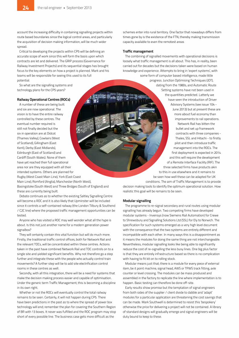
railway operational centres (rocs)A number of these are being built
and six are now operational. The vision is to have the entire railway controlled by these centres. The eventual number required is still not finally decided but the six in operation are at didcot (Thames Valley), Cowlairs (West of Scotland), Gillingham (east kent), derby (east Midlands), edinburgh (east of Scotland) and Cardiff (South Wales). none of them have yet reached their full operational area nor are they equipped with all their intended systems. others are planned for Rugby (West Coast Main Line), york (east Coast Main Line), Romford (Anglia), Manchester (north West), Basingstoke (South West) and Three Bridges (South of england) and these are currently being built.
debate continues as to whether the existing Saltley Signalling Centre will become a RoC and it is also likely that Upminster will be included since it controls a self-contained railway (the London Tilbury & Southend / C2C line) where the proposed traffic management opportunities can be tested.
Anyone who has visited a RoC may well wonder what all the hype is about. is this not just another name for a modern generation power signalbox?
They will certainly contain this vital function but will do much more. Firstly, the traditional traffic control offices, both for network Rail and the relevant ToCs, will be concentrated within these centres. Actions taken in the past have combined network Rail and ToC controls on to a single site and yielded significant benefits. Why not therefore go a step further and integrate these with the people who actually control train movements? A further step will be to add site electrification control rooms in these centres as well.
Secondly, with all this integration, there will be a need for systems that make the decision making process easier and capable of optimisation. Under the generic term Traffic Management, this is becoming a discipline in its own right.
Whether or not the RoCs will eventually control the total railway remains to be seen. Certainly, it will not happen during CP5. There have been predictions in the past as to where the spread of power box technology will end; remember the plan for covering the Southern Region of BR with 13 boxes. it never was fulfilled and the RoC program may stop short of every possible line. The business case gets more difficult as the
schemes enter into rural territory. one factor that nowadays differs from times gone by is the existence of the FTn, thereby making transmission capacity available to even the remotest areas
traffic managementThe combining of signalled movements with operational decisions is
loosely what traffic management is all about. This has, in reality, been carried out for decades but the decisions taken were based on human knowledge and experience. Attempts to bring in ‘expert systems’, with
some form of computer based intelligence, made little progress. Junction optimising Techniques (JoT),
dating from the 1980s, and Automatic Route Setting systems have not been used in
the quantities predicted. Latterly we have seen the introduction of driver
Advisory Systems (see issue 104 - June 2013) but at present these are
more about fuel economy than improvements to rail operations.
network Rail has bitten the bullet and set up framework contracts with three companies - Thales, SSL and hitachi - to firstly
pilot and then introduce traffic management into the RoCs. The
first deployment is expected in 2014 and this will require the development
of a Remote interface Facility (RiF). The three selected firms have products akin
to this in use elsewhere and it remains to be seen how well these can be adapted for Uk
conditions. The aim of Traffic Management is to provide decision making tools to identify the optimum operational solution. how realistic this goal will be remains to be seen.
modular signallingThe programme to re-signal secondary and rural routes using modular
signalling has already begun. Two competing firms have developed modular systems - invensys (now Siemens Rail Automation) for Crewe to Shrewsbury and Signalling Solutions Ltd (SSL) for ely to norwich. The specification for such systems emerged as a very high level document with the consequence that the two systems are entirely different and incompatible with each other. in many ways this is a disappointment as it means the modules for doing the same thing are not interchangeable. nevertheless, modular signalling looks like being able to significantly reduce the cost of re-signalling the less busy lines. one big plus factor is that they are entirely infrastructure based so there is no complication with having to fit kit on to rolling stock.
Modular means just that; there is a module for every piece of external item, be it point machine, signal head, AWS or TPWS track fitting, axle counter or level crossing. The modules can be mass produced and assembled in the factory to replicate the line where implementation is to happen. Basic testing can therefore be done off-site.
early results show promise but the temptation of signal engineers from both sides of the supplier / client divide to dabble and ‘adapt’ modules for a particular application are threatening the cost savings that can be made. Mark Southwell is determined to resist this ‘bespokery’ otherwise the price for delivering a project will not be contained. A library of standard designs will gradually emerge and signal engineers will be duty bound to keep to these.
the rail engineer • September 201324
SIGNETAutomatic Re-configuration for Signalling Power
camlinrail.com
SIGNET “Innovation of the Year” shortlist
Eliminates train delays
Automatic restoration of supply
Counteracts cable theft by re-configuring power supply
Saves time and money
Over 750 SIGNETs installed on Crossrail & West Coast Mainline
Available for 650V and 400V, IT or TN signalling schemes. Class I & Class II compliant

level crossingsAnother advance in CP5 will be to make level crossings safer.
Several high profile accidents in recent times demand that technology improvements should be explored to achieve this. AhBs (automatic half barriers) and open crossings carry the highest level of risk. The development of automated four-barrier crossings using obstacle detector technology but without CCTV monitoring is broadly completed, although there are teething problems with the performance of the LidAR (Light detection and Ranging) equipment that detects any objects near to the ground. it is reliability rather than safety that causes the difficulty since, if equipment fails to produce a crossing clear condition, the barriers will not raise and the crossing stays closed to road traffic. keeping the lenses clean will require changes to the maintenance routines. As Mark Southwell commented, one has to persevere with these problems in order to make progress and a significant roll out of this crossing type will happen in the five year period.
ertms / etcsThe introduction of the european Rail Traffic Management System
(or more succinctly the european Train Control System) into main line operation is probably the biggest challenge in CP5. With valuable lessons learned from the Cambrian Line deployment, the next step is the integration trial about to commence on the hertford Loop line, known as eniF (eTCS national integration Facility). here, the four main contenders for eTCS business - Siemens (formerly invensys), SSL, Ansaldo and infrasig (a consortium of Bombardier Rail Control Solutions and Carillion) - will be required to provide both ground and train-based equipment and demonstrate that interoperability between the different supplier offerings can be achieved. Testing of the system using a specially adapted Class 313 eMU will begin in September, which will include testing of the GPRS (General Packet Radio Service) as part of the GSM-R element.
Assuming all goes well, planning can then start with confidence to equip the London end of the GW main line in readiness for the Crossrail opening in 2018 and then moving westwards to Reading, Bristol, Cardiff and beyond. All of this has to go hand in glove with the RoC deployment to ensure that compatibility with signalling systems that already exist in these centres is achieved.
Another eTCS challenge will be on the central section of Thameslink, this being declared as the chosen train control system but with the requirement to add in an overlay Automatic Train operation (ATo) package, which has still to be developed.
routine investment it must not be forgotten that many re-signalling schemes using
traditional systems and equipment (SSi and its successor computer based interlockings) will continue. The Signalling Framework contracts let to invensys (now Siemens), SSL, and Atkins were based upon network Rail’s confidence in these firms to competently deliver in the Uk environment. Atkins, being essentially a consultancy and design organisation with no manufacturing facility, is different to the other two. not locked in to any particular product, it will be free to deploy equipment from other manufacturers some of whom will be from overseas. This will require obtaining product approval, which can be a slow process but the advantage of being able to use ‘best in class’ equipment from across the world is potentially useful.
The increasing content of signalling equipment that is train borne requires some organisational decisions to be made as to who does what. Train fitment will be carried out by the ToCs and RoSCos but where will responsibility for system performance lie? it is anticipated that network Rail will be accountable for system safety. There has been talk in the past of creating a ‘Systems Authority’ but this step has yet to be taken. network Rail will look carefully at what is happening within european railways to see what practice will suit the Uk best.
Signalling in CP5 is going to be an exciting time but, above all, network Rail has a desire to share knowledge and ensure that no restrictive practices creep in. Good relationships with AToC and the ToCs are in place, such that project control boards have been set up and signalling requirements may be written into future Franchise agreements. Close contact is kept with the eRTMS Users’ Group in Brussels and with the professional engineering institutions in the Uk. it is confidently predicted that there will be much to write about in the coming months and years.
ANOTHER ADVANCE IN CP5 WILL MAKE LEVEL
CROSSINGS SAFER. SEVERAL HIGH PROFILE
ACCIDENTS IN RECENT TIMES DEMAND THAT
TECHNOLOGY IMPROVEMENTS SHOULD BE
EXPLORED TO ACHIEVE THIS...
the rail engineer • September 201326
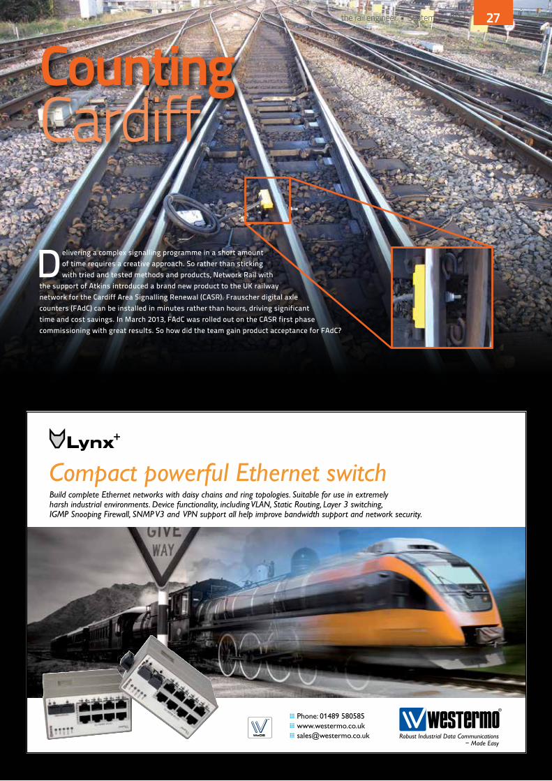
Delivering a complex signalling programme in a short amount of time requires a creative approach. So rather than sticking with tried and tested methods and products, Network Rail with
the support of Atkins introduced a brand new product to the UK railway network for the Cardiff Area Signalling Renewal (CASR). Frauscher digital axle counters (FAdC) can be installed in minutes rather than hours, driving significant time and cost savings. In March 2013, FAdC was rolled out on the CASR first phase commissioning with great results. So how did the team gain product acceptance for FAdC?
CountingCardiff
the rail engineer • September 2013 27
Under CASR, Atkins is responsible for designing, managing and implementing the replacement of life-expired signalling and associated power and distribution equipment across 192 route miles of track. This is no easy feat and, with only four years to complete the work, the project team knew that it had to do things differently to deliver the project on time. FAdC seemed like the perfect solution as it is similar to the Thales AzLm offering that has been used in the Uk for some years now but with some striking differences.
clamps not holesWhat makes FAdC so
innovative is that it vastly reduces the amount of time staff need to spend trackside from construction, test and maintenance. The FAdC detection head point is fitted to the rail by a clamp so it can be fitted on-site in a matter of minutes as drilling the rail web is eliminated. no trackside interface module is required, which again reduces the need for staff to work on-site, and it also has diagnostic support systems that are more informative to the maintainer and give quicker and more accurate faulting from the control centre should it be required.
The clamp installation feature also provided the team with a solution for resignalling Cardiff Central station which is due by Christmas 2014. The Cardiff station area has a very dense p-way layout which means that drilling the rail web is not an option. however, as FAdC does not require any drilling to be installed, it was a great way to overcome this challenge. due to the significant benefits FAdC could provide, Atkins offered it as an efficiency saving under the CASR scheme at time of tender.
acceptance and designThe first step for Conor Linnell,
Atkins’ project director for CASR and the FAdC innovation, was to actively engage with network Rail and Frauscher to work out a plan of attack for the Cardiff application
approval. having established that a product acceptance extension was required, the whole process consisted of the following elements: » Cross acceptance from
Germany with supporting safety certification from a German independent Safety Authority;
» network Rail main product approval process;
» Additional electromagnetic compatibility (eMC) trials in the Uk in both AC and dC traction areas.
While the eMC trials were ongoing, Atkins then started designing its first application for FAdC with the help of Frauscher and network Rail. A number of key staff travelled to Frauscher’s headquarters in Austria for training on all elements of design, construction and testing, including data production.
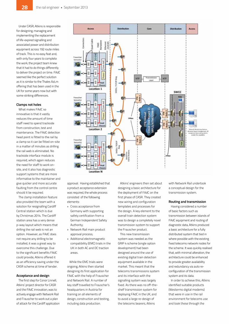
Atkins’ engineers then set about designing a basic architecture for the deployment of FAdC on the first phase of CASR. They created new wiring and configuration templates and processes for the design. A key element to the overall train detection system was to design a completely novel transmission system to support the Frauscher product.
This new transmission system was needed as the GRiP 4 scheme (single option development) had been designed around the use of existing digital train detection equipment available in the market. This meant that the telecoms transmissions system and its interface with the signalling system was largely fixed. As there was no off-the-shelf transmission system for deploying FAdC in the Uk, and to avoid a large re-design of the telecoms bearers, Atkins
with network Rail undertook a conceptual design for the transmission system.
routing and transmissionhaving considered a number
of basic factors such as transmission between islands of FAdC equipment and routing of diagnostic data, Atkins produced a basic architecture for a fully distributed system that tied in where possible with the existing fixed telecoms network nodes for the scheme. it was quickly realised that, with minimal alteration, the architecture could be enhanced to provide greater availability and redundancy via auto re-configuration of the transmission system and its data.
in order to achieve this, Atkins identified suitable products (Westermo digital modems) that were in use in the rail environment for telecoms use and took these through the
the rail engineer • September 201328
Frauscher Sensortechnik GmbH
St. Marienkirchen | AT | [email protected]
Frauscher Polska Sp. z o. o.
Katowice | PL | [email protected]
Frauscher UK Ltd.
Yeovil | UK | [email protected] Sensor Technology (Beijing) Co. Ltd.
Beijing | CN | [email protected]
USE FUTURETECHNOLOGY
Axle Counting & Wheel DetectionReliable all over the world!
TODAY.
www.frauscher.com
product acceptance process to support the signalling application. The end result is a transmission system that has a number of significant benefits both operationally and for the maintainer. it not only uses the in-built FAdC diagnostics but also the network managed software solution to monitor and interrogate the transmission system and its constituent parts.
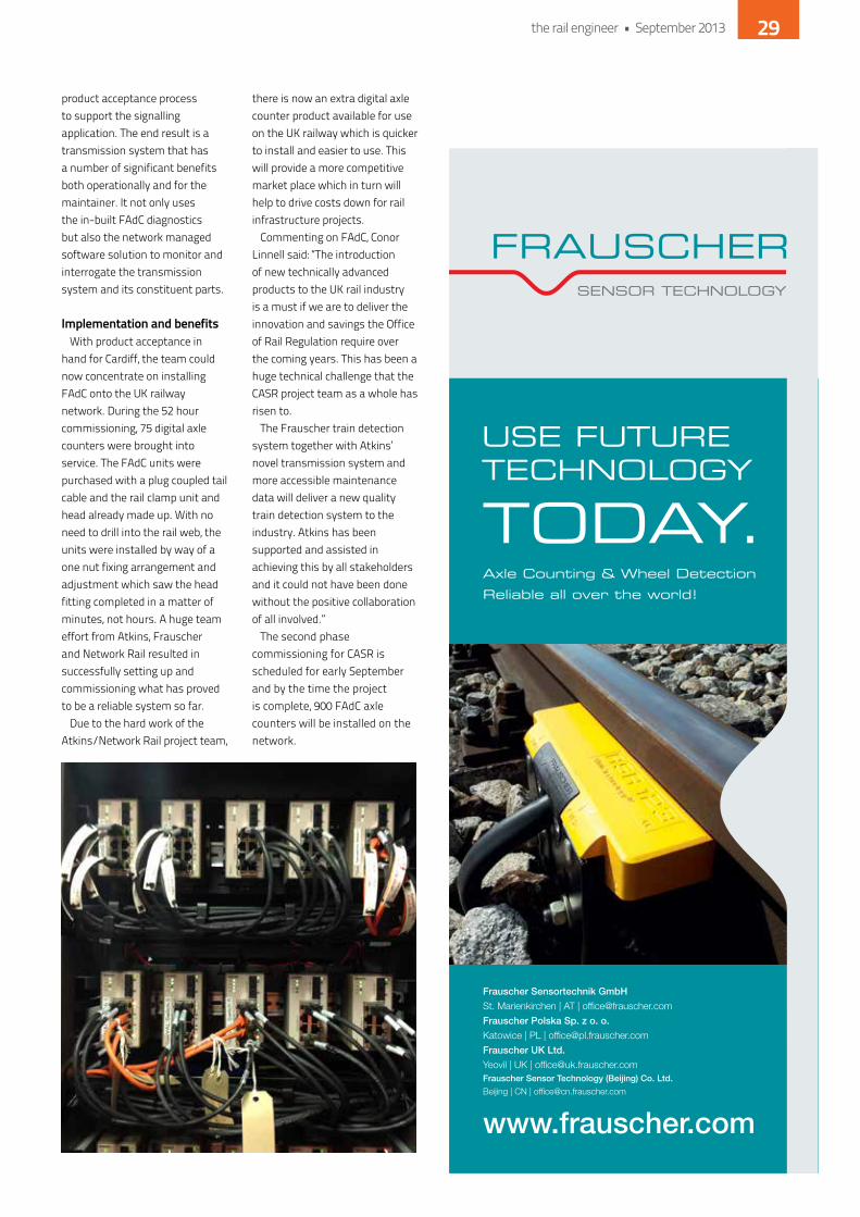
implementation and benefitsWith product acceptance in
hand for Cardiff, the team could now concentrate on installing FAdC onto the Uk railway network. during the 52 hour commissioning, 75 digital axle counters were brought into service. The FAdC units were purchased with a plug coupled tail cable and the rail clamp unit and head already made up. With no need to drill into the rail web, the units were installed by way of a one nut fixing arrangement and adjustment which saw the head fitting completed in a matter of minutes, not hours. A huge team effort from Atkins, Frauscher and network Rail resulted in successfully setting up and commissioning what has proved to be a reliable system so far.
due to the hard work of the Atkins/network Rail project team,
there is now an extra digital axle counter product available for use on the Uk railway which is quicker to install and easier to use. This will provide a more competitive market place which in turn will help to drive costs down for rail infrastructure projects.
Commenting on FAdC, Conor Linnell said: “The introduction of new technically advanced products to the Uk rail industry is a must if we are to deliver the innovation and savings the office of Rail Regulation require over the coming years. This has been a huge technical challenge that the CASR project team as a whole has risen to.
The Frauscher train detection system together with Atkins’ novel transmission system and more accessible maintenance data will deliver a new quality train detection system to the industry. Atkins has been supported and assisted in achieving this by all stakeholders and it could not have been done without the positive collaboration of all involved.”
The second phase commissioning for CASR is scheduled for early September and by the time the project is complete, 900 FAdC axle counters will be installed on the network.
the rail engineer • September 2013 29
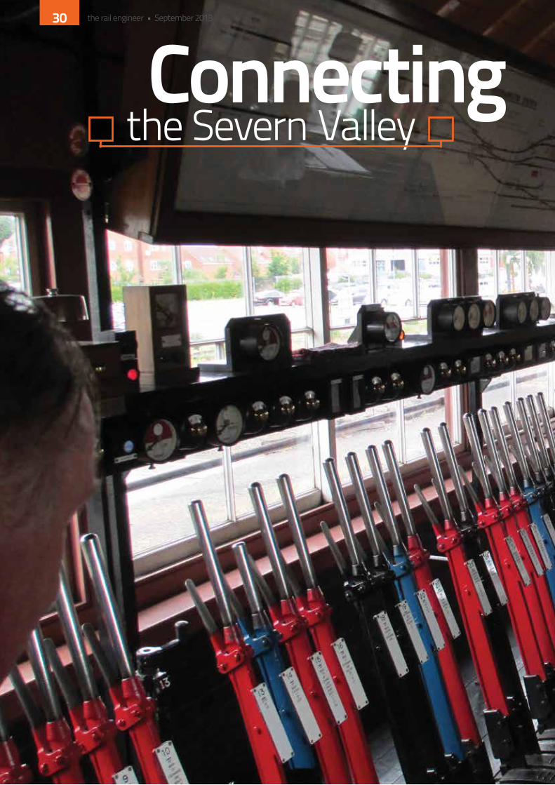
Connectingthe Severn Valley
the rail engineer • September 201330
it is a common belief amongst the heritage railway community that having a main line connection is good for business. This not only facilitates stock movements in and out but, with the right signalling off the main line, charter trains can visit the line and bring commercial benefits.
The Severn Valley Railway (SVR) has long had such a connection but this was via a trailing connection not fitted with facing point locks making movements a somewhat tortuous affair. All that has now changed, but the circumstances are interesting.
Previous connectionkidderminster, the junction for the Severn
Valley Railway, had a traditional mechanical signal box on the line from Birmingham to Worcester. A trailing crossover between the up and down line, allowed terminating trains to reverse there. The signal box operated the points and the associated shunt signals for the Severn Valley Railway connection.
in August 2012, the main line was re-signalled and came under the control of the West Midlands Signalling Centre (WMSC) located at Saltley. This project incorporated the provision of a new facing crossover on the main line to make the reversal of terminating trains easier. it was quickly realised that this would create a facing movement over the points leading on to the Severn Valley Railway meaning that they would need to be equipped with a facing point lock.
Why therefore not make this a fully signalled route thus facilitating quick and easy movement on to and off the heritage line? negotiations with network Rail commenced with mutual benefits being realised by both parties and a collaborative design was prepared.
design and implementationThe Severn Valley Railway had constructed
a GWR replica signal box at kidderminster in 1987 to control the station throat and associated sidings as well as the line towards Bewdley. This box now became a fringe box to the WMSC. The connecting line also serves as access to the SVR Carriage Works, a facility created from the old Goods Shed.
The SVR is entirely equipped with mechanical semaphore or shunt signals, but clearly a signalled main line connection would need to be colour lights to the latest standard, protected by full track circuiting. So who should control the points and signals?
The solution was a joint participation. A release from kidderminster SVR Box allows the WMSC to operate both ends of the point connection and slots allow it to clear the appropriate signal from either the Up or down platform on the main line onto the SVR. depending on which levers are pulled in kidderminster box, this can either be a main line aspect that clears the route towards Bewdley or a position light that allows movement only within station limits.
The section from kidderminster to Bewdley is controlled by acceptance levers instead of the more usual token instruments that exist on the rest of the railway’s single line sections, so having to stop to pick up a token is avoided.
The departure signal from the SVR is an Led colour light where the main aspect is controlled by WMSC once the points are reversed. on the same post is a position light signal worked from a lever in kidderminster Box that controls entry to the carriage works. To save using another lever for controlling the exit from these sidings, the mechanical disc exit signal is wired in parallel with this, both thus showing clear aspects at the same time.
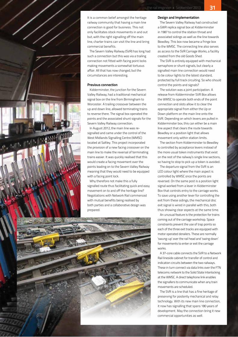
An unusual feature is the protection for trains coming out of the carriage workshop. Space constraints prevent the use of trap points so each of the three exit tracks are equipped with motor operated derailers. These are normally ‘swung-up’ over the rail head and ‘swing down’ for movements to enter or exit the carriage works.
A 37-core cable connects the SVR to a network Rail lineside cabinet for transfer of control and indication circuits between the two railways. These in turn connect via data links over the FTn telecoms network to the Solid State interlocking at the WMSC. A direct telephone link enables the signallers to communicate when any train movements are scheduled.
The SVR is a line that has a fine heritage of preserving for posterity mechanical and relay technology. With its new main line connection, it now has signalling that spans 180 years of development. May the connection bring it new commercial opportunities as well.
the rail engineer • September 2013 31
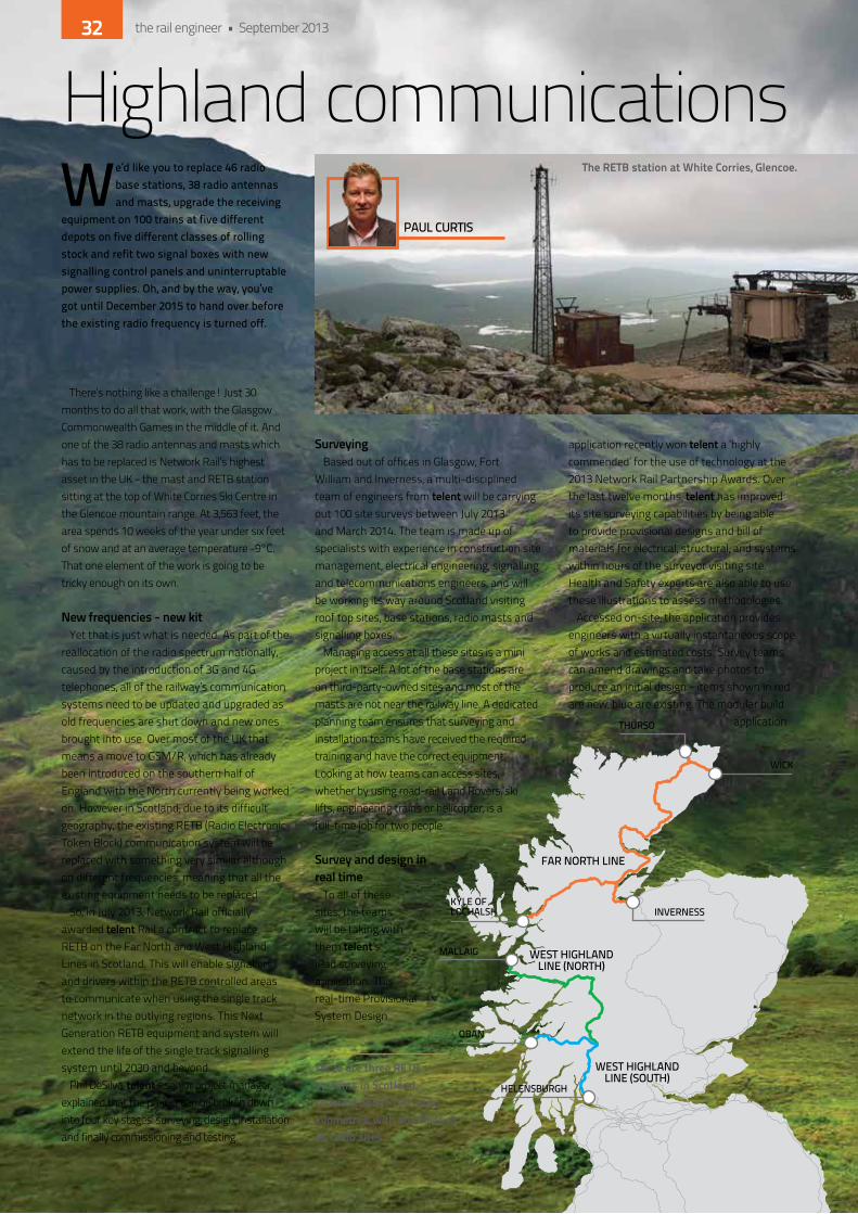
There’s nothing like a challenge! Just 30 months to do all that work, with the Glasgow Commonwealth Games in the middle of it. And one of the 38 radio antennas and masts which has to be replaced is network Rail’s highest asset in the Uk - the mast and ReTB station sitting at the top of White Corries Ski Centre in the Glencoe mountain range. At 3,563 feet, the area spends 10 weeks of the year under six feet of snow and at an average temperature -9°C. That one element of the work is going to be tricky enough on its own.
new frequencies - new kityet that is just what is needed. As part of the
reallocation of the radio spectrum nationally, caused by the introduction of 3G and 4G telephones, all of the railway’s communication systems need to be updated and upgraded as old frequencies are shut down and new ones brought into use. over most of the Uk that means a move to GSM/R, which has already been introduced on the southern half of england with the north currently being worked on. however in Scotland, due to its difficult geography, the existing ReTB (Radio electronic Token Block) communication system will be replaced with something very similar although on different frequencies, meaning that all the existing equipment needs to be replaced.
So, in July 2013, network Rail officially awarded telent Rail a contract to replace ReTB on the Far north and West highland Lines in Scotland. This will enable signallers and drivers within the ReTB controlled areas to communicate when using the single track network in the outlying regions. This next Generation ReTB equipment and system will extend the life of the single track signalling system until 2030 and beyond.
Phil deSilva, telent’s senior project manager, explained that the project can be broken down into four key stages: surveying, design, installation and finally commissioning and testing.
surveyingBased out of offices in Glasgow, Fort
William and inverness, a multi-disciplined team of engineers from telent will be carrying out 100 site surveys between July 2013 and March 2014. The team is made up of specialists with experience in construction site management, electrical engineering, signalling and telecommunications engineers, and will be working its way around Scotland visiting roof top sites, base stations, radio masts and signalling boxes.
Managing access at all these sites is a mini project in itself. A lot of the base stations are on third-party-owned sites and most of the masts are not near the railway line. A dedicated planning team ensures that surveying and installation teams have received the required training and have the correct equipment. Looking at how teams can access sites, whether by using road-rail Land Rovers, ski lifts, engineering trains or helicopter, is a full-time job for two people.
survey and design in real time
To all of these sites, the teams will be taking with them telent’s iPad surveying application. This real-time Provisional System design
application recently won telent a ‘highly commended’ for the use of technology at the 2013 network Rail Partnership Awards. over the last twelve months, telent has improved its site surveying capabilities by being able to provide provisional designs and bill of materials for electrical, structural, and systems within hours of the surveyor visiting site. health and Safety experts are also able to use these illustrations to assess methodologies.
Accessed on-site, the application provides engineers with a virtually instantaneous scope of works and estimated costs. Survey teams can amend drawings and take photos to produce an initial design - items shown in red are new, blue are existing. The modular build
application
Highland communicationsWe’d like you to replace 46 radio
base stations, 38 radio antennas and masts, upgrade the receiving
equipment on 100 trains at five different depots on five different classes of rolling stock and refit two signal boxes with new signalling control panels and uninterruptable power supplies. Oh, and by the way, you’ve got until December 2015 to hand over before the existing radio frequency is turned off.
FAR NORTH LINE
WEST HIGHLANDLINE (NORTH)
WEST HIGHLANDLINE (SOUTH)
OBAN
MALLAIG
KYLE OFLOCHALSH
WICK
THURSO
INVERNESS
HELENSBURGH
PAUL CURTIS
there are three retb systems in scotland, covering about 700 route kilometres, with 68 radios at 46 radio sites.
the retb station at White corries, glencoe.
the rail engineer • September 201332

works with AutoCAd WS and other applications.
A range of generic codes can be ‘drag and dropped’ onto the photos to illustrate what is required to meet the scope. By streaming these photos back to the office, and having face-to-face discussions with designers through the iPad’s ‘Face-Time’ application, technical queries can be answered in real time, whilst still on site. This advance should allow the telent surveying team to visit each site only once and not go back until installation and commissioning.
To date, this method has been used on contracts for PA renewals with network Rail in Scotland and with northern Rail. Surveying teams can carry out dilapidation reports, look
at the space available for designers to install new equipment and consider where power supplies will be installed - all during their first site visit.
designAlthough much of the work can now be
carried out whilst the surveys are being carried out, telent designers will also be working with radio equipment manufacturer Comms design Limited which has previous experience of the ReTB radio hardware system in Scotland.
As well as designing and installing the radio base stations, the project also includes fitting train-borne radio systems to approximately 100 units on five different train classes - 37, 66, 67, 156 and 158. These are based at five different depots, Corkerhill, Polmadie, inverness, Mossend and Crewe. With different passenger train operators, freight operators and rolling stock owners being involved as well, this element of the project is also very complicated and will require precise planning. There are even a few heritage steam locomotives that will need to be fitted out.
Two Signal Boxes at Banavie and inverness signal boxes will be fitted out with new signalling equipment, control panels and UPS.
installationBoth aspects of installation, base stations
and masts and the train borne installations, will commence in 2014. A number of teams with ladders, Land Rovers, climbing equipment and the aforementioned iPads will be deployed around Scotland working on the infrastructure. The trains and locomotives will be fitted out at their home depots and some of this work is likely to be subcontracted to specialist rolling-stock companies.
And to answer the question on how one does install a new radio mast on top of a mountain, the solution is obvious - by helicopter.
testing and commissioningtelent will be carrying out trials on the West
highland line between May and August 2014 to prove the systems performance. once this initial trial is signed off, and as installations get further underway, there will be more progressive testing of the system, backbone testing of the network, link testing of the sites and linking them to the signalling boxes.
Then there will be the de-commissioning of redundant equipment and migrating from the old system to the new ready for handover at the end of december 2015. it’s a challenge - but the teams from telent are relishing it and looking forward to a couple of years of fresh mountain air.
1926 693000
FAR NORTH LINE
WEST HIGHLANDLINE (NORTH)
WEST HIGHLANDLINE (SOUTH)
OBAN
MALLAIG
KYLE OFLOCHALSH
WICK
THURSO
INVERNESS
HELENSBURGH
the rail engineer • September 2013 33

The cost of railway signalling systems has long been a concern to infrastructure management and several initiatives to introduce cheaper, more efficient practices have emerged in recent times. One
such is ‘plug and play’ cabling for lineside signalling circuits. Network Rail recently staged a couple of one-day seminars for signalling suppliers and engineers to examine the technology, look at the benefits and be honest about the downsides.
The term ‘plug and play’ is copied from the computer industry but it is a misnomer in the rail context. Plug is correct, but the system as designed is very far from Play since the free mixing of cable terminations is certainly not intended.
the conceptThe installation and termination
of lineside cabling is time consuming, expensive, manpower intensive and carries safety risks. if the majority of this work, including subsequent testing, could be transferred to a factory environment, then significant cost and efficiency benefits will result.
Signalling systems are made up of a set of basic components: » An intelligence unit, normally
known as an interlocking; » A control desk from which train
movements are directed; » Lineside apparatus cases
where the ‘intelligence’ is locally terminated;
» end devices such as signals, points, level crossings, track circuits and axle counters that determine the passage of trains.
Whilst the intelligence and circuitry has advanced from vast
banks of relays to computer based systems, the cabling to connect these components together has remained substantially similar. Multicore copper cables of various sizes are still the norm, designed originally for dC circuits but, with the advent of solid state interlockings, now also carrying low-bit-rate digital signals.
Run out in standard lengths, sometimes from a cable train but now generally hand pulled, the cable cores are terminated on 2BA sliding links mounted vertically in equipment rooms and lineside cases. Since the latter occur at regular intervals, the cable ends are fully terminated every time and instances of direct in-line jointing of cables are rare. After the termination is completed, surplus cable invariably becomes scrap.
What, therefore, if all this cabling could be made to measure and plug coupled into the various termination points and end devices? network Rail has been studying and implementing the concept and started by setting up a partnership with cabling equipment suppliers and the signalling contractors. From the beginning, it was realised that, for
Signalling Plug and Play Cabling
PhoT
o: U
niP
ART
the rail engineer • September 201334
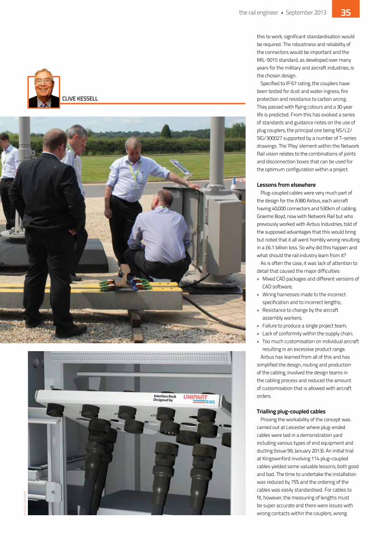
this to work, significant standardisation would be required. The robustness and reliability of the connectors would be important and the MiL-5015 standard, as developed over many years for the military and aircraft industries, is the chosen design.
Specified to iP 67 rating, the couplers have been tested for dust and water ingress, fire protection and resistance to carbon arcing. They passed with flying colours and a 30 year life is predicted. From this has evolved a series of standards and guidance notes on the use of plug couplers, the principal one being nS/L2/SiG/300027 supported by a number of T-series drawings. The ‘Play’ element within the network Rail vision relates to the combinations of joints and disconnection boxes that can be used for the optimum configuration within a project.
lessons from elsewherePlug-coupled cables were very much part of
the design for the A380 Airbus, each aircraft having 40,000 connectors and 530km of cabling. Graeme Boyd, now with network Rail but who previously worked with Airbus industries, told of the supposed advantages that this would bring but noted that it all went horribly wrong resulting in a £6.1 billion loss. So why did this happen and what should the rail industry learn from it?
As is often the case, it was lack of attention to detail that caused the major difficulties: » Mixed CAd packages and different versions of
CAd software; » Wiring harnesses made to the incorrect
specification and to incorrect lengths; » Resistance to change by the aircraft
assembly workers; » Failure to produce a single project team; » Lack of conformity within the supply chain; » Too much customisation on individual aircraft
resulting in an excessive product range.Airbus has learned from all of this and has
simplified the design, routing and production of the cabling, involved the design teams in the cabling process and reduced the amount of customisation that is allowed with aircraft orders.
trialling plug-coupled cables Proving the workability of the concept was
carried out at Leicester where plug-ended cables were laid in a demonstration yard including various types of end equipment and ducting (issue 99, January 2013). An initial trial at kingswinford involving 114 plug-coupled cables yielded some valuable lessons, both good and bad. The time to undertake the installation was reduced by 75% and the ordering of the cables was easily standardised. For cables to fit, however, the measuring of lengths must be super accurate and there were issues with wrong contacts within the couplers, wrong
CLIVE KESSELL
PhoT
o: U
niP
ART
the rail engineer • September 2013 35
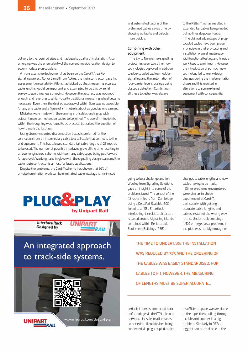
delivery to the required sites and inadequate quality of installation. Also emerging was the unsuitability of the current lineside location design to accommodate plug couplers.
A more extensive deployment has been on the Cardiff Area Re-signalling project. Conor Linnell from Atkins, the main contractor, gave his assessment on suitability. Atkins had picked up that measuring accurate cable lengths would be important and attempted to do this by aerial survey to avoid manual surveying. however, the accuracy was not good enough and reverting to a high-quality traditional measuring wheel became necessary. even then, the desired accuracy of within 3cm was not possible for any one cable and a figure of ± 1 metre is about as good as one can get.
Mistakes were made with the running in of cables ending up with adjacent male connectors on cables to be joined. The use of in-line joints within the troughing was found to be practical but raised the question of how to mark the location.
Using stump-mounted disconnection boxes is preferred for the connection from an intermediary cable to a tail cable that connects to the end equipment. This has allowed standard tail cable lengths of 25 metres to be used. The number of possible interfaces grew all the time resulting in an over-engineered scheme with too many cable types being put forward for approval. Working hand in glove with the signalling design team and the cable route contractor is a must for future applications.
despite the problems, the Cardiff scheme has shown that 95% of on-site termination work can be eliminated, cable wastage is minimised
and automated testing of the preformed cables saves time by showing up faults and defects more quickly.
combining with other equipment
The ely to norwich re-signalling project has seen two other new technologies deployed in addition to plug-coupled cables: modular signalling and the automation of four-barrier level crossings using obstacle detection. Combining all these together was always
going to be a challenge and John Woolley from Signalling Solutions gave an insight into some of the problems faced. The control of the 42 route miles is from Cambridge using a deltaRail Scalable ieCC linked to an SSL Smartlock interlocking. Lineside architecture is based around ‘signalling islands’ contained within Re-locatable equipment Buildings (ReB) at
periodic intervals, connected back to Cambridge via the FTn telecom network. Lineside location cases do not exist, all end devices being connected via plug-coupled cables
to the ReBs. This has resulted in extended tail cables being needed but no lineside power feeds.
The claimed advantages of plug-coupled cables have been proven in principle in that pre-testing and installation were all made easy with functional testing and lineside work kept to a minimum. however, the introduction of so much new technology led to many design changes during the implementation phase and this resulted in alterations to some external equipment with consequential
changes to cable lengths and new cables having to be made.
other problems encountered were similar to those experienced at Cardiff, particularly with getting accurate cable lengths and cables installed the wrong way round. Undertrack crossings (UTX) emerged as a problem. if the pipe was not big enough or
insufficient space was available in the pipe, then pulling through a cable and coupler is a big problem. Similarly in ReBs, a bigger than normal hole in the
An integrated approach to track-side systems.
Untitled-1 1 01/07/2013 12:33:39
www.unipartrail.com/plug-and-play
Plug & Play quarter page Aug 2013.indd 1 05/08/2013 17:03
THE TIME TO UNDERTAKE THE INSTALLATION
WAS REDUCED BY 75% AND THE ORDERING OF
THE CABLES WAS EASILY STANDARDISED. FOR
CABLES TO FIT, HOWEVER, THE MEASURING
OF LENGTHS MUST BE SUPER ACCURATE...
the rail engineer • September 201336
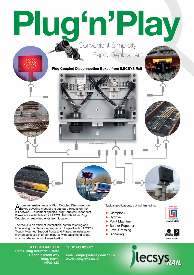
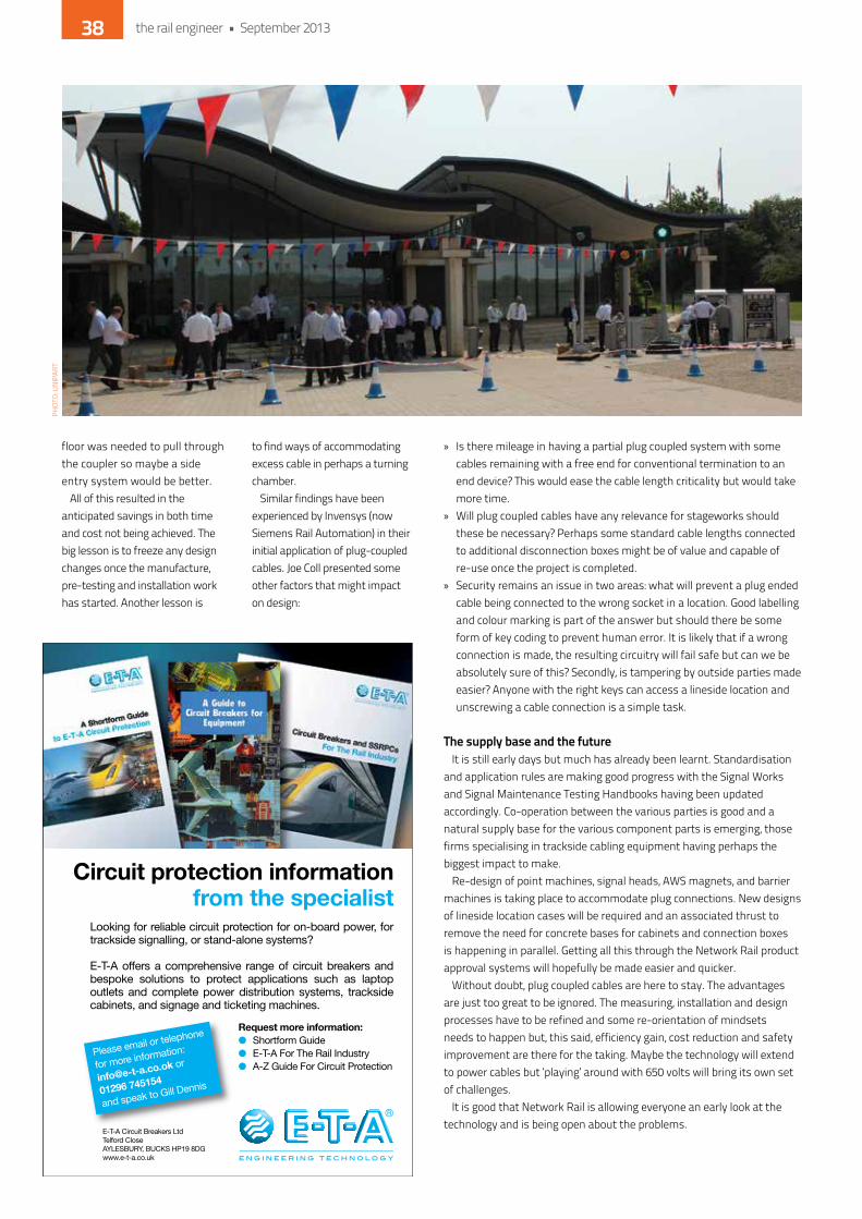
floor was needed to pull through the coupler so maybe a side entry system would be better.
All of this resulted in the anticipated savings in both time and cost not being achieved. The big lesson is to freeze any design changes once the manufacture, pre-testing and installation work has started. Another lesson is
to find ways of accommodating excess cable in perhaps a turning chamber.
Similar findings have been experienced by invensys (now Siemens Rail Automation) in their initial application of plug-coupled cables. Joe Coll presented some other factors that might impact on design:
» is there mileage in having a partial plug coupled system with some cables remaining with a free end for conventional termination to an end device? This would ease the cable length criticality but would take more time.
» Will plug coupled cables have any relevance for stageworks should these be necessary? Perhaps some standard cable lengths connected to additional disconnection boxes might be of value and capable of re-use once the project is completed.
» Security remains an issue in two areas: what will prevent a plug ended cable being connected to the wrong socket in a location. Good labelling and colour marking is part of the answer but should there be some form of key coding to prevent human error. it is likely that if a wrong connection is made, the resulting circuitry will fail safe but can we be absolutely sure of this? Secondly, is tampering by outside parties made easier? Anyone with the right keys can access a lineside location and unscrewing a cable connection is a simple task.
the supply base and the futureit is still early days but much has already been learnt. Standardisation
and application rules are making good progress with the Signal Works and Signal Maintenance Testing handbooks having been updated accordingly. Co-operation between the various parties is good and a natural supply base for the various component parts is emerging, those firms specialising in trackside cabling equipment having perhaps the biggest impact to make.
Re-design of point machines, signal heads, AWS magnets, and barrier machines is taking place to accommodate plug connections. new designs of lineside location cases will be required and an associated thrust to remove the need for concrete bases for cabinets and connection boxes is happening in parallel. Getting all this through the network Rail product approval systems will hopefully be made easier and quicker.
Without doubt, plug coupled cables are here to stay. The advantages are just too great to be ignored. The measuring, installation and design processes have to be refined and some re-orientation of mindsets needs to happen but, this said, efficiency gain, cost reduction and safety improvement are there for the taking. Maybe the technology will extend to power cables but ‘playing’ around with 650 volts will bring its own set of challenges.
it is good that network Rail is allowing everyone an early look at the technology and is being open about the problems.
Circuit protection informationfrom the specialist
Looking for reliable circuit protection for on-board power, for trackside signalling, or stand-alone systems?
E-T-A offers a comprehensive range of circuit breakers and bespoke solutions to protect applications such as laptop outlets and complete power distribution systems, trackside cabinets, and signage and ticketing machines.
Request more information:Shortform GuideE-T-A For The Rail IndustryA-Z Guide For Circuit Protection
E-T-A Circuit Breakers LtdTelford Close AYLESBURY, BUCKS HP19 8DGwww.e-t-a.co.uk
Please email or telephone
for more information:
01296 745154
and speak to Gill Dennis
PhoT
o: U
niP
ART
the rail engineer • September 201338

Two of the strongest organisations in rail automation, Siemens and Invensys Rail, have joined together as Siemens Rail Automation.
We are leading the way in signalling, with our 170 year track record for innovative solutions and customer focused delivery.
Our strong local network and knowledge plus our high level of expertise will enable us to work more closely and efficiently with our customers, the world over.
Now we’re building on our strong foundations to provide customers with reliable, advanced technologies for today and the future.
Experience integrated mobility.
Building an even better service for our customersTwo businesses have become one major force
siemens.co.uk/rail
Answers for infrastructure and cities.

At nearly £15 billion, Crossrail is Europe’s largest current construction project. It will provide faster, more frequent main-line trains right into the heart of London, linking Heathrow directly with the City and Canary Wharf, connecting towns in the East and
the West to central London, and delivering faster cross-city journeys between stations like Paddington, Liverpool Street, Whitechapel and Stratford.
The new route will pass through 37 stations and run 118 kilometres from Maidenhead and heathrow in the west, through two new 21 kilometre tunnels beneath central London, out to Shenfield in the east and Abbey Wood in the south-east. A fleet of new trains will operate a 24 train per hour service between Paddington and Liverpool Street, with 12 trains per hour running to Stratford and Canary Wharf.
communications-based systemTo enable this high-frequency operation,
Crossrail Limited (CRL) created a detailed performance specification for the central section. This will be delivered under the Signalling and Control System Contract (C620). outside that central section, trains will operate over existing network Rail tracks and infrastructure, and under the control of network Rail signalling and control systems.
To the west of Paddington, this will be on Great Western main line (GWML), and it is planned that trains will operate under european Train Control System (eTCS) control.
To the east of the Pudding Mill Lane portal (where Crossrail trains heading eastward emerge from the central section tunnels), signalling will be controlled by the existing network Rail interlocking at Liverpool Street. however, between Pudding Mill Lane and Stratford, Crossrail trains will interoperate with non-Crossrail trains bound for the existing Liverpool Street station platforms.
Throughout the central section, trains will be driven and controlled automatically by a communication-based train control (CBTC) system in moving-block automatic train operation (ATo) mode, allowing them to operate closer together and to run with precise speed control and stopping accuracy, all the more important because the underground platforms will be fitted with platform screen doors with which the train must align accurately when it stops.
CBTC systems are usually found on metro systems because they enable shorter headways and so higher capacities, particularly where stations are close together - this is one of the key advantages of moving block.
Controlling CrossrailFRANK FOLEY,SENIOR PROJECT ENGINEER,SIEMENS RAIL AUTOMATION
the rail engineer • September 201340

combined approachThe contract was awarded in november 2012
to a consortium of Siemens and invensys Rail. Between them, the two companies offered a combination of proven technology and delivery experience to the project. of course, following the company’s acquisition in May 2013, invensys Rail is now an integral part of Siemens Rail Automation which retains responsibility for the ‘conventional’ signalling scope of the C620 contract.
There are no conventional lineside signals in the central section because the CBTC provides in-cab signalling to the driver, but axle counter train detection, points control and route-setting will be managed by the company’s latest-generation WeSTRACe interlocking.
The interlocking will interface with the Trainguard CBTC and with the automatic train supervision (ATS) systems (both of which are also within the scope of the C620 contract) at a new control centre which is being constructed at ilford in essex. in the control room, operators will oversee the running of the railway, and will have a large digital ‘Line Wide overview display’ in addition to their operator workstations.
detailed analysis is underway to design the display layouts, both at the control centre and the driver’s display in the cab, ensuring that data is displayed in a clear format, that critical data is easily identifiable, and that operators are not overloaded with lower-priority messages.
comprehensive engineeringAlthough the signalling and control system is just one small part of the final railway, it will be
one of the last to complete in 2018, and so has a significant importance to overall completion and hand-over to passenger service. To minimise delivery risk, the system will use existing, proven products, systems and sub-systems and will avoid new development as far as possible - although inevitably, as with every railway, the signalling and control system has to be tailored to the specific requirements of layout and functionality. in addition, new interfaces between the Siemens Trainguard MT system and the WeSTRACe interlocking will be developed.
A comprehensive systems-engineering approach is being employed on the project to assure delivery and to make sure validation and verification evidence is established from the outset. The company is currently developing the formal System Requirement Specification, to relate the functionality of the final system to the requirements of the client, and to provide linked requirement tracing through to subsystem design level.
The client’s approach has been unique and technically knowledgeable. The specification is thorough and comprehensive, and generally functionality-based rather than overly prescriptive. This gives the delivery contractor leeway in its approach to system design and engineering, although this must always be fully supported by comprehensive safety assurance and compliance with relevant standards. This approach is to some extent the product of an unusual contract. Based on the institute of Civil engineering’s neC (new engineering Contract) form of contract, it has a ‘pain-share, gain-share’ mechanism. it is a target cost contract, but if the contractor spends less than the target or identifies a cost-saving, the benefits are shared with the client, so it is in both parties interests to deliver optimum value-for-money.
complex interfacesThe signalling and control system has a significant number of complex interfaces especially with
the new Crossrail rolling stock. To enable a smooth transition of trains from network Rail operation in the outer sections to CBTC in the central section, interfaces will be developed at the service control level and at the interlocking level - these interfaces with network Rail being seen as key to delivering an integrated, tested and validated railway.
Another key interface is with the platform screen door (PSd) system. This will be the first delivery of PSds in the Uk since London Underground’s Jubilee Line extension project, and technology has progressed significantly since then. The Crossrail system will provide new functionality which automatically inhibits a platform door from opening if the corresponding train door is identified as faulty by the train management system, and vice versa if a platform door is faulty. The signalling and control system provides the high-integrity data link between the train and the PSds to ensure that they are only opened at the right time - when a train is stationary in the platform.
Recognising the complexity of these interfaces, the client awarded the signalling and control system relatively early in the project - the new tunnels are still being bored, and some of the stations are still in their civil engineering phase. This early engagement allows the interface details with partnering contracts to be agreed at an early stage, particularly with civil engineering contractors and network Rail.
Completion and hand-over in 2018 may seem a long way off, but there is a huge amount of work to do before then. Siemens’ teams in Chippenham, Braunschweig and London are already progressing well with design and systems engineering and over the next five years, the company will be tackling the challenges of integrating all these complex systems to ensure that this, London’s newest railway, and europe’s biggest construction project, is delivered successfully.
the rail engineer • September 2013 41
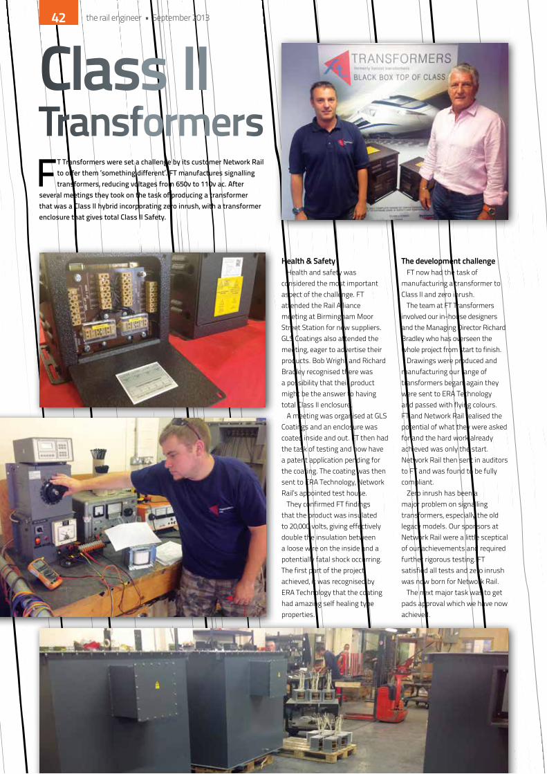
Health & safetyhealth and safety was
considered the most important aspect of the challenge. FT attended the Rail Alliance meeting at Birmingham Moor Street Station for new suppliers. GLS Coatings also attended the meeting, eager to advertise their products. Bob Wright and Richard Bradley recognised there was a possibility that their product might be the answer to having total Class ii enclosure.
A meeting was organised at GLS Coatings and an enclosure was coated inside and out. FT then had the task of testing and now have a patent application pending for the coating. The coating was then sent to eRA Technology, network Rail’s appointed test house.
They confirmed FT findings that the product was insulated to 20,000 volts, giving effectively double the insulation between a loose wire on the inside and a potentially fatal shock occurring. The first part of the project achieved, it was recognised by eRA Technology that the coating had amazing self healing type properties.
the development challengeFT now had the task of
manufacturing a transformer to Class ii and zero inrush.
The team at FT Transformers involved our in-house designers and the Managing director Richard Bradley who has overseen the whole project from start to finish.
drawings were produced and manufacturing our range of transformers began, again they were sent to eRA Technology and passed with flying colours. FT and network Rail realised the potential of what they were asked for and the hard work already achieved was only the start. network Rail then sent in auditors to FT and was found to be fully compliant.
Zero inrush has been a major problem on signalling transformers, especially the old legacy models. our sponsors at network Rail were a little sceptical of our achievements and required further rigorous testing. FT satisfied all tests and zero inrush was now born for network Rail.
The next major task was to get pads approval which we have now achieved.
Class II TransformersFT Transformers were set a challenge by its customer Network Rail
to offer them ‘something different’. FT manufactures signalling transformers, reducing voltages from 650v to 110v ac. After
several meetings they took on the task of producing a transformer that was a Class II hybrid incorporating zero inrush, with a transformer enclosure that gives total Class II Safety.
the rail engineer • September 201342

new ProductFT Transformers have done it! The company are the
first to develop a full Class ii zero inrush transformer, with an outstanding health & safety coating. FT have priced their range at least 30% more competitive than its competitors with more outstanding features.
nG Bailey, network Rail’s supplier of the year, is a customer of FT Transformers. They have calculated that, if FT’s zero inrush transformers had been available for recent projects, a saving of £200,000 could have been achieved just by using smaller sized cables.
FT have secured £100,000 grant from Bournville College Post Growth Fund. They recognised that the company has a product worthy of investment to expand over the next twelve months in machinery, test equipment and technology.
earls court exhibitionFT Transformers attended Railex at earls Court earlier in the year with a stand arranged by
Rail Alliance. This proved an excellent opportunity to show the world what FT had achieved. They attended meetings with Uk Trade & industry, representatives from denmark and Turkey were at the show and were very informative. The sponsor from network Rail has also shown an interest in a joint information share of the european and Asian rail requirements that would recognise network Rail’s specification.
This will give FT Transformers a great opportunity to expand into the export market.The future looks bright for FT Transformers!
the rail engineer • September 2013 43
Readers of The Rail Engineer will be familiar with some of the sophisticated signalling systems in use on the national network in this country. The signal interlocking is a basic logic system that monitors every input from the signaller, checks for availability, and prevents a conflicting move being set up. In the driver’s cab it is a different matter. Drivers are continuously reading the line ahead and adjusting the traction
controls in accordance with all these visual inputs, including signal aspects, speed restrictions, platforms to call at and buffer stops at the terminus. Driving a train requires a high level of continuous concentration. Despite the dedication and professionalism of the driving fraternity, the occasional momentary lapse has the potential for serious consequences.
Back in July this year, the internet and TV news channels hosted video footage of a Class 730 train on the express route from Madrid to Ferrol lifting off the track into a catastrophic derailment on a curve at Santiago de Compostela in north-west Spain. This section of line uses the Spanish ASFA system of cab warnings supplemented with automatic braking. Signal aspect and speed data is transmitted to the train by means of balises in the track. Contemporary media reports indicated that the line speed was 50mph but the train derailed at 111mph. it was also suggested that additional infill balises may have averted the disaster.
Could this possibly happen in the Uk? Sadly in the last 50 years there have been six spectacular derailments due to excessive speed resulting in a total of 19 fatalities. The responses to these and other significant accidents in this country have led to a significantly safer Uk national rail network.
To monitor the variables on the line head and check that a driver is appropriately controlling the speed of the train is technically challenging. it is no surprise that technical developments to ensure that ‘driver error’ is nipped in the bud before any damage is done have lagged behind safety improvements in the signal box. nevertheless, train cabs have, over the years, been increasingly fitted with a variety of safety systems. invariably, the impetus to develop and implement these systems has been a recommendation from an accident involving loss of life. Such lessons of history are enshrined in the detail of RSSB Group Standards and network Rail standards.
Train protection and driver aids
DAVID BICKELL
the rail engineer • September 201344
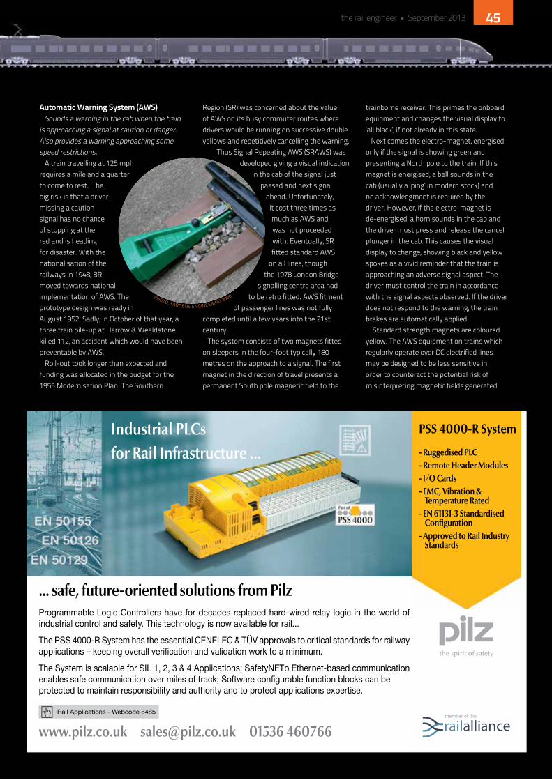
automatic Warning system (aWs)Sounds a warning in the cab when the train
is approaching a signal at caution or danger. Also provides a warning approaching some speed restrictions.
A train travelling at 125 mph requires a mile and a quarter to come to rest. The big risk is that a driver missing a caution signal has no chance of stopping at the red and is heading for disaster. With the nationalisation of the railways in 1948, BR moved towards national implementation of AWS. The prototype design was ready in August 1952. Sadly, in october of that year, a three train pile-up at harrow & Wealdstone killed 112, an accident which would have been preventable by AWS.
Roll-out took longer than expected and funding was allocated in the budget for the 1955 Modernisation Plan. The Southern
Region (SR) was concerned about the value of AWS on its busy commuter routes where drivers would be running on successive double yellows and repetitively cancelling the warning.
Thus Signal Repeating AWS (SRAWS) was developed giving a visual indication
in the cab of the signal just passed and next signal
ahead. Unfortunately, it cost three times as much as AWS and was not proceeded with. eventually, SR fitted standard AWS
on all lines, though the 1978 London Bridge
signalling centre area had to be retro fitted. AWS fitment
of passenger lines was not fully completed until a few years into the 21st century.
The system consists of two magnets fitted on sleepers in the four-foot typically 180 metres on the approach to a signal. The first magnet in the direction of travel presents a permanent South pole magnetic field to the
trainborne receiver. This primes the onboard equipment and changes the visual display to ‘all black’, if not already in this state.
next comes the electro-magnet, energised only if the signal is showing green and presenting a north pole to the train. if this magnet is energised, a bell sounds in the cab (usually a ‘ping’ in modern stock) and no acknowledgment is required by the driver. however, if the electro-magnet is de-energised, a horn sounds in the cab and the driver must press and release the cancel plunger in the cab. This causes the visual display to change, showing black and yellow spokes as a vivid reminder that the train is approaching an adverse signal aspect. The driver must control the train in accordance with the signal aspects observed. if the driver does not respond to the warning, the train brakes are automatically applied.
Standard strength magnets are coloured yellow. The AWS equipment on trains which regularly operate over dC electrified lines may be designed to be less sensitive in order to counteract the potential risk of misinterpreting magnetic fields generated
Rail Applications - Webcode 8485
... safe, future-oriented solutions from Pilz
www.pilz.co.uk [email protected] 01536 460766
Industrial PLCs for Rail Infrastructure ...
PSS 4000-R System
- Ruggedised PLC- Remote Header Modules- I/O Cards- EMC, Vibration & Temperature Rated- EN 61131-3 Standardised Confi guration- Approved to Rail Industry Standards
Programmable Logic Controllers have for decades replaced hard-wired relay logic in the world of industrial control and safety. This technology is now available for rail...
The PSS 4000-R System has the essential CENELEC & TÜV approvals to critical standards for railway applications – keeping overall verifi cation and validation work to a minimum.
The System is scalable for SIL 1, 2, 3 & 4 Applications; SafetyNETp Ethernet-based communication enables safe communication over miles of track; Software confi gurable function blocks can be protected to maintain responsibility and authority and to protect applications expertise.
Rail Engineer April - Railtex.indd 1 3/12/2013 12:44:08 PM
PhoTo: yARdene enGineeRinG 2000
the rail engineer • September 2013 45
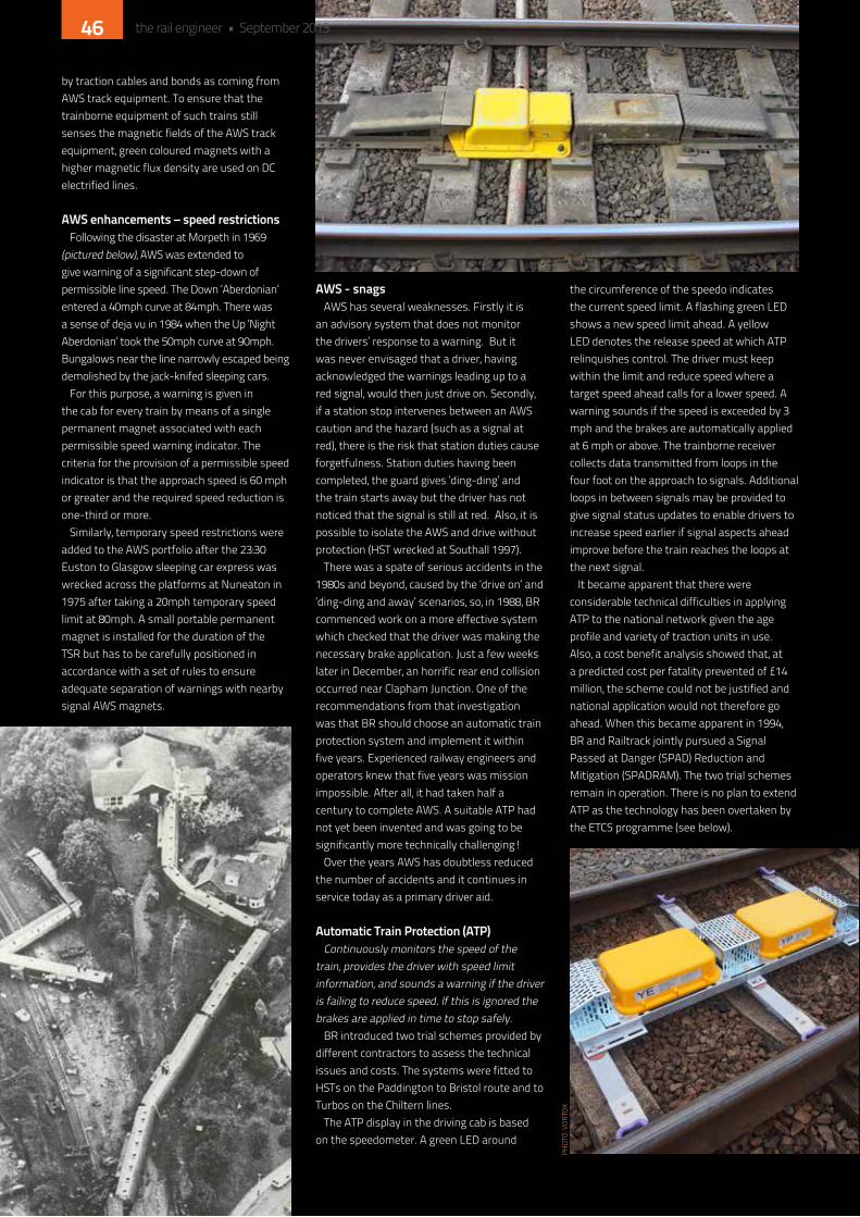
by traction cables and bonds as coming from AWS track equipment. To ensure that the trainborne equipment of such trains still senses the magnetic fields of the AWS track equipment, green coloured magnets with a higher magnetic flux density are used on dC electrified lines.
aWs enhancements – speed restrictionsFollowing the disaster at Morpeth in 1969
(pictured below), AWS was extended to give warning of a significant step-down of permissible line speed. The down ‘Aberdonian’ entered a 40mph curve at 84mph. There was a sense of deja vu in 1984 when the Up ‘night Aberdonian’ took the 50mph curve at 90mph. Bungalows near the line narrowly escaped being demolished by the jack-knifed sleeping cars.
For this purpose, a warning is given in the cab for every train by means of a single permanent magnet associated with each permissible speed warning indicator. The criteria for the provision of a permissible speed indicator is that the approach speed is 60 mph or greater and the required speed reduction is one-third or more.
Similarly, temporary speed restrictions were added to the AWS portfolio after the 23:30 euston to Glasgow sleeping car express was wrecked across the platforms at nuneaton in 1975 after taking a 20mph temporary speed limit at 80mph. A small portable permanent magnet is installed for the duration of the TSR but has to be carefully positioned in accordance with a set of rules to ensure adequate separation of warnings with nearby signal AWS magnets.
aWs - snagsAWS has several weaknesses. Firstly it is
an advisory system that does not monitor the drivers’ response to a warning. But it was never envisaged that a driver, having acknowledged the warnings leading up to a red signal, would then just drive on. Secondly, if a station stop intervenes between an AWS caution and the hazard (such as a signal at red), there is the risk that station duties cause forgetfulness. Station duties having been completed, the guard gives ‘ding-ding’ and the train starts away but the driver has not noticed that the signal is still at red. Also, it is possible to isolate the AWS and drive without protection (hST wrecked at Southall 1997).
There was a spate of serious accidents in the 1980s and beyond, caused by the ‘drive on’ and ‘ding-ding and away’ scenarios, so, in 1988, BR commenced work on a more effective system which checked that the driver was making the necessary brake application. Just a few weeks later in december, an horrific rear end collision occurred near Clapham Junction. one of the recommendations from that investigation was that BR should choose an automatic train protection system and implement it within five years. experienced railway engineers and operators knew that five years was mission impossible. After all, it had taken half a century to complete AWS. A suitable ATP had not yet been invented and was going to be significantly more technically challenging!
over the years AWS has doubtless reduced the number of accidents and it continues in service today as a primary driver aid.
automatic train Protection (atP)Continuously monitors the speed of the
train, provides the driver with speed limit information, and sounds a warning if the driver is failing to reduce speed. if this is ignored the brakes are applied in time to stop safely.
BR introduced two trial schemes provided by different contractors to assess the technical issues and costs. The systems were fitted to hSTs on the Paddington to Bristol route and to Turbos on the Chiltern lines.
The ATP display in the driving cab is based on the speedometer. A green Led around
the circumference of the speedo indicates the current speed limit. A flashing green Led shows a new speed limit ahead. A yellow Led denotes the release speed at which ATP relinquishes control. The driver must keep within the limit and reduce speed where a target speed ahead calls for a lower speed. A warning sounds if the speed is exceeded by 3 mph and the brakes are automatically applied at 6 mph or above. The trainborne receiver collects data transmitted from loops in the four foot on the approach to signals. Additional loops in between signals may be provided to give signal status updates to enable drivers to increase speed earlier if signal aspects ahead improve before the train reaches the loops at the next signal.
it became apparent that there were considerable technical difficulties in applying ATP to the national network given the age profile and variety of traction units in use. Also, a cost benefit analysis showed that, at a predicted cost per fatality prevented of £14 million, the scheme could not be justified and national application would not therefore go ahead. When this became apparent in 1994, BR and Railtrack jointly pursued a Signal Passed at danger (SPAd) Reduction and Mitigation (SPAdRAM). The two trial schemes remain in operation. There is no plan to extend ATP as the technology has been overtaken by the eTCS programme (see below).
PhoT
o: V
oRTo
k
the rail engineer • September 201346
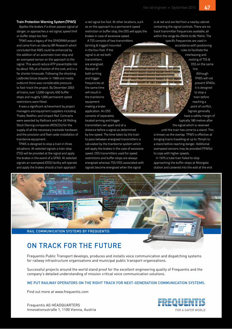
train Protection Warning system (tPWs)Applies the brakes if a driver passes signal at
danger, or approaches a red signal, speed limit or buffer stops too fast.
TPWS was a legacy of the SPAdRAM project and came from an idea by BR Research which concluded that AWS could be enhanced by the addition of an automatic train stop and an overspeed sensor on the approach to the signal. This would reduce ATP preventable risk by about 70%, at a fraction of the cost, and in a far shorter timescale. Following the shocking Ladbroke Grove disaster in 1999 and media outburst there was considerable pressure to fast-track the project. By december 2003 all trains, over 12,000 signals, 650 buffer stops and roughly 1,000 permanent speed restrictions were fitted.
it was a significant achievement by project managers and equipment suppliers including Thales, Redifon, and Unipart Rail. Contracts were awarded by Railtrack and the Uk Rolling Stock owning companies (RoSCos) for the supply of all the necessary trackside hardware and the provision and fleet-wide installation of trainborne equipment.
TPWS is designed to stop a train in three situations. At selected signals a train stop (TSS) will be provided at the signal and apply the brakes in the event of a SPAd. At selected signals an overspeed (oSS) facility will operate and apply the brakes should a train approach
a red signal too fast. At other locations, such as on the approach to a permanent speed restriction or buffer stop, the oSS will apply the brakes in case of excessive speed.
A TSS consists of two transmitters (arming & trigger) mounted in the four foot. if the signal is at red both transmitters are energised. Receipt of both arming and trigger frequencies at the same time will result in the trainborne equipment making a brake application. An oSS consists of separately located arming and trigger transmitters set apart and at a distance before a signal as determined by line speed. The time taken by the train to pass between energised transmitters is calculated by the trainborne system which will apply the brakes in the case of excessive speed. oSS transmitters used for speed restrictions and buffer stops are always energised whereas TSS/oSS associated with signals become energised when the signal
is at red and are fed from a nearby cabinet containing the signal controls. There are six track transmitter frequencies available, all within the range 64.25khz to 66.75khz. The
specific frequencies are used in accordance with positioning
rules to facilitate the interleaving and
nesting of TSS & oSS on the same
line. Although
TPWS will not prevent SPAds, it is designed to stop a
train before reaching a
point of conflict. Signals generally
have a safety margin of typically 180 metres after
the signal which is reserved until the train has come to a stand. This
is known as the overlap. TPWS is effective at bringing trains travelling at up to 75mph to a stand before reaching danger. Additional overspeed sensors may be provided (TPWS+) to cope with higher speeds.
in 1975 a tube train failed to stop approaching the buffer stops at Moorgate station and careered into the wall at the end
Frequentis AG HEADQUARTERS Innovationsstraße 1, 1100 Vienna, Austria FOR A SAFER WORLD
ON TRACK FOR THE FUTURE
RAIL COMMUNICATION SYSTEMS BY FREQUENTIS
Frequentis Public Transport develops, produces and installs voice communication and dispatching systemsfor railway infrastructure organisations and municipal public transport organisations.
Successful projects around the world stand proof for the excellent engineering quality of Frequentis and thecompany's detailed understanding of mission critical voice communication solutions.
WE PUT RAILWAY OPERATORS ON THE RIGHT TRACK FOR NEXT-GENERATION COMMUNICATION SYSTEMS.
Find out more at www.frequentis.com
rail_ad_190x130_0813_Layout 1 21.08.13 14:40 Seite 1
the rail engineer • September 2013 47

of the tunnel killing forty-three people. on the national system, the risk was addressed by adjusting the aspect sequence leading to a terminal platform. originally, at many terminal stations, the signal authorising a move into the platform would display a green aspect. This was changed to maximum single yellow thereby ensuring drivers would receive an AWS caution before reaching the buffer stops. The provision of TPWS buffer stop oSS closes out the residual risk.
driver’s reminder appliance (dra)Cuts traction power.This was introduced into the driving cab from 1998 as a measure to
try and reduce ‘ding-ding and away’ type SPAds. it is not connected to the signalling system and requires the driver to operate it in a proactive manner when a train is held at a red signal.
it consists of a switch on the driving desk which when pressed or pushed down, activates the device into ‘set’ mode. The switch displays a red light when set. This prevents the driver taking power. Reset is achieved by pulling up the switch/button.
trainstopshalts a train that passes a red signal.Mechanical trainstops are used on lines over which London
Underground trains operate and on a few other lines with a metro-style service. A trainstop is mounted near the signal and the arm is raised when the signal is at danger. When the tripcock on the train is engaged by a raised trainstop arm, a brake application is automatically initiated.
tilt authorisation and speed supervision (tass)enables tilting trains to run at higher speeds than non tilting trains,
where authorised to do so.TASS has been installed on some sections of the West Coast main
line (WCML) and cross country routes to enable tilting trains such as Pendolino Class 390 and Voyager Class 221 to run at enhanced permissible speeds providing the tilt mechanism is functional. it also prevents tilting where clearances are restricted. TASS is a more sophisticated system than was originally provided for the tilting Advanced Passenger Train (APT) on WCML. C-APT (Control-APT) consisted of passive transponders in the four foot coded with the line speed. These were interrogated by the trainborne equipment to give the driver a digital speed limit display. Although development of the APT came to an end in the mid 1980s, some transponders are believed to still be in situ.
TASS uses eurobalise passive transmitters mounted in the four foot which define the areas over which each train may safely tilt. Speed profiles and tilt authorisation data in eRTMS packet 44 structure is received by the trainborne equipment. The speed of the train is continuously supervised and enhanced permissible speed authorised providing the carriage tilting mechanisms are healthy. The cab ‘speed supervised’ blue light confirms tilt systems are working, balises are being read and the speed supervised according to the profile for the type of train and location. The driver may run at the enhanced permissible speeds that are displayed on lineside signs. TASS intervenes when overspeeding is detected, sounding a warning and slowing the train by 25mph before allowing the driver to continue as a non-tilting train.
european train control system (etcs)Provides cab signalling and train protection functions.The Cambrian lines pilot scheme has previously been covered in depth
in the The Rail Engineer. The national project is now moving ahead with a hertford national integration Facility (hniF). kit from several suppliers will be tested on a five mile section of the hertford loop prior to national roll-out. A Class 313 eMU has been converted into an eTCS laboratory.
in addition to the various train protection systems described above, there are still some others used in the Uk. Such systems are used on hS1, London Underground, and metro style railways/tramways in the Uk. Perhaps they will form the basis of a future article in The Rail Engineer.
the rail engineer • September 201348
We do more than just paperworkSure, we are synonymous with independent assurance: we inspected our first locomotive boiler in 1929 and have been assuring products, processes and entire railways ever since. Our portfolio of independent assurance services remains world-beating.
But expert advice is the backbone of our business. From asset management to energy efficiency, from signalling systems to vehicle design, we are helping rail businesses across the world operate in a safe, efficient and sustainable manner.
To discover how we can help your business contact us today.
E-mail: [email protected] Twitter: @LR_Railwww.lr.org/rail
Lloyd’s Register is a trading name of Lloyd’s Register Group Limited and its subsidiaries. For further details please see: http://www.lr.org/entities © Lloyd’s Register Group Limited 2012

While you won’t have seen the URS logo emblazoned on cranes, diggers or tipper-trucks, it is nonetheless a company that lies behind many of the UK’s most complex construction projects - nowhere more so than in the rail sector. As one of the world’s
leading engineering design companies, URS undertakes a vital role that typically goes unseen.
however, with revenues of $11 billion, this 50,000-person strong company with offices in nearly 50 countries is a force to be reckoned with. URS’ track record includes some of the largest global railway projects ever undertaken and spans the full spectrum of light, metro, high speed, heavy rail and heavy haul rail markets.
Across the business, URS has won a string of new contracts to work on some of the Uk’s most important infrastructure projects. The company is heavily involved in developing the country’s rail infrastructure and has recently won significant new programmes of work in rail as well as major extensions to long-term projects.
banking on successLast month, dragados SA formally
appointed URS as lead design consultant for the £563m Bank station capacity upgrade project. URS had previously supported dragados throughout the 15-month tender process which led to the Spanish contractor’s appointment to the scheme by London Underground Limited (LUL) in July 2013. URS’ integrated design team, including Wilkinson eyre Architects and dr Sauer & Partners, will deliver a wide range of multidisciplinary services, including design management and assurance; civil, structural, geotechnical, mechanical and electrical engineering;
tunnelling; architecture; pedestrian flow modelling; and planning and environmental services. Staff from URS and dragados will share an office with London Underground for the duration of the project.
The designs will include a new northern line southbound-running tunnel to create more platform space, interchange tunnels and another station entrance. The new tunnels will pass under iconic city landmarks including the Mansion house and other important listed buildings within a conservation area. The station will remain operational throughout the construction although there will be a temporary blockade of the northern line while the new section of southbound tunnel is connected.
URS also continues to win new commissions from Crossrail. Since 2008, URS has been one of the largest design consultants on the project, having worked on both the preliminary and detailed design phases of the surface routes as well as the underground central section. it gained the necessary expertise working on some of the world’s most modern metros, including Athens, dubai, hong kong and Singapore.
High-profile activitiesThe same level of insight has been brought
to the high Speed Two project where the company holds four contracts with two other designers, Mott Macdonald to provide
engineering services and Arup to provide environmental services, both under the framework agreements for Phases one and Two of the project.
Borders Railway, which is being delivered by network Rail in partnership with Transport Scotland, will be the longest new domestic railway constructed in Britain for over 100 years. Following a long association with the project through the development stages, URS’ role recently involved collaborative working with BAM nuttall to provide outline design services. URS is now providing detailed design services to BAM nuttall, with construction underway for completion in 2015.
Alongside its work on these high-profile engineering design and construction projects, URS is also heavily involved in the modernisation of the Uk’s existing network. it is a major provider for network Rail’s ‘switches and crossings’ renewal programme, and is one of three design firms currently providing detailed integrated permanent way and signalling solutions for the national programme. This renewal programme is just one example of the kind of cradle-to-grave service that URS has provided to network Rail for many years.
The company’s success extends to europe where it is playing a major role in modernising Croatia’s entire rail network. The Croatia Railways programme comprises upgrades and extensions to help the nation’s rail network meet eU requirements. Through its multidisciplinary design services role, URS will double the track on existing lines within Croatia as well as its links with other european countries.
breaks coverURS
PhoT
o: T
RAn
SPoR
T Fo
R Lo
ndo
n
the rail engineer • September 201350

gearing up for growthURS is committed to developing its staff. Training employees to help
them reach their full potential is an integral part of the company’s ethos. A continued commitment to quality, health and safety remains paramount as the company expands. There are teams dedicated to driving through improvements in these important areas, with all employees well versed in the latest industry requirements.
Collaboration, alliances and partnerships with contractors will continue to be of particular importance for the company going forward. Around half of URS’ current work in rail is now carried out for contractors on a design and build basis. The company sees significant opportunities to collaborate further with contractors and expand the breadth and scope of its work.
“our extensive client base in rail - ranging from infrastructure owners, contractors and government agencies, through to train operators, developers and financiers - reflects the breadth and diversity of our services,” explains ian hay, director of rail at URS. “We remain dedicated to building solid relationships with our clients and partners in the rail sector.”
URS’ two-pronged strategy is to work with design and build contractors as well as operators such as network Rail. “our dual approach gives our teams a constant stream of exciting, long-term projects,” hay continues. “URS is one of a limited number of major consultants that does such a volume of work for contractors. importantly, it means our staff can see their engineering designs and vision realised. in Glasgow we have a team of engineers working on Borders Rail, for instance, and in 45 minutes the guys can be on site seeing their work converted into reality.”
recruiting for the futureURS’ growth has created many new career opportunities. it has nearly
100 new openings in rail to be filled by January 2014, so URS is keen to make contact with both experienced professionals and those looking to develop their careers. With a strong pipeline of projects, demand is set to rise throughout the next 12 months.
Working for a leading global brand that is winning a steady stream of major rail projects is proving a big draw for candidates. But having a long-term career path, with a tailored training and development programme, is equally important. The opportunity to take on a meaningful role on a project from day one is another key factor attracting new employees to the company.
Among the many rail positions URS is looking to fill, the company is recruiting engineers, senior engineers and principal engineers in overhead line electrification. Signalling design and telecoms engineers at various levels are also sought. There are numerous openings for bridge engineers, as well as opportunities for structural and civil engineers with experience gained in different sectors to work on rail projects. The company is also seeking permanent way engineers at various levels.
engineering project managers with the skills and experience to manage and integrate a diverse range of rail projects are also urgently required. hay is particularly keen to hire project managers who can excel in a design and build environment, working directly with contractors.
Swindon and Bristol are two of the hotspots in the Uk where URS is intensifying its search. The company is hosting a recruitment event in Swindon on 18 September, and another in Bristol on 25 September, so that potential applicants interested in learning more about URS can meet members of the rail team.
For more details about career opportunities at URS, please visit its dedicated careers website - or email to register for the Swindon and Bristol events. See also URS’ advertisement on page 83.
www.ursglobal.com/careers [email protected]
PhoT
o: h
iGh
SPe
ed T
Wo
LiM
iTed
PhoT
o: T
RAn
SPoR
T Fo
R Lo
ndo
n
the rail engineer • September 2013 51

At all levels, a fatality is terrible. It pervades every aspect of life. Families, work colleagues - the effects are profound and long lasting. Our strategy is intended to get rid of fatal incidents once and for all. This will take some time and, unfortunately, bad things may happen on the way, but focusing on delivering our
strategy will take us to a better place. So getting rid of the fatalities is our main task and is the main reason for introducing the Life Saving Rules. Life saving - because, to use a current cliché, that’s what it says on the tin.
lines in the sandhow did all this start? Well, we spent a lot of time
looking at the root causes of all the fatalities and life changing injuries of the previous 12 years. We tried to work out and understand what rule we could have had in place at the time that would have prevented them. We wanted to find simple lines in the sand that everyone would understand. Many other companies including national Grid and Anglo American, where i worked before joining network Rail, as well as Shell and other oil and gas companies have been down this route as well.
We’re often quoted as being the safest railway in europe which is fine, but actually there are plenty of other industries that are way ahead of us. The power, oil and gas industries have made huge strides. They’ve put lots of effort behind some of the system type risks and leadership capabilities. Rather than reinvent the wheel,
i’m keen that we learn from organisations that have very similar characteristics to us in particular areas.
So, think of working with an adjacent line open and the risk of having people around big pieces of equipment. The mining industry has that with their huge haul trucks and people walking all around their sites. The ports have forklift trucks and big containers moving in close proximity to people.
safety summiti think the level of understanding of the Life Saving
Rules in our business is improving and i’m really pleased that they have been adopted by all of our principal contractors. They are sufficiently minded about safety that they are pursuing this approach for their own reasons anyway, which is particularly encouraging.
in April, we had a safety summit with all of our principal contractors. The managing directors sat down with us to go through some of the safety incidents we’d had. it was an opportunity to remind them of the reasons why we’ve established the Life Saving Rules along with the ‘fair culture’. it’s to try to get to a fundamental understanding as to why things happen and i’ve been encouraged by the reactions of our
Safety rulesrule!
GARETH LLEWELLYNSAFETY AND SUSTAINABLE DEVELOPMENT DIRECTOR,NETWORK RAIL
the rail engineer • September 201352
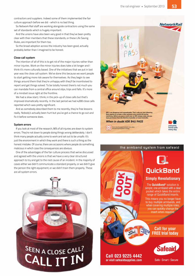
contractors and suppliers. indeed some of them implemented the fair culture approach before we did - which is no bad thing.
So network Rail staff are working alongside contractors using the same set of standards which is hugely important.
And the unions have also been very good in that they’ve been pretty clear with their members that these standards, or these Life Saving Rules, are important for them too.
So the broad adoption across the industry has been good, actually probably better than i imagined to be honest.
close call systemThe intention of all of this is to get rid of the major injuries rather than
minor injuries. Work on the minor injuries does take a lot longer and i think it’s more culturally based. one of the initiatives that we put in last year was the close call system. We’ve done this because we want people to start getting more risk aware for themselves. As they begin to see things around them that they’re unhappy with they’ll be incentivised to report and get things solved. To be totally honest there’s not much you can mandate from a central office around slips, trips and falls. it’s more of a mindset issue right at the frontline.
We had a slow start, i think, in the pick-up of close calls but that’s improved dramatically recently. in the last period we had 4,000 close calls reported which was pretty significant.
And as somebody described them to me recently, they’re free lessons really. nobody’s actually been hurt but you’ve got a chance to go out and fix it before someone does.
system errorsif you look at most of the research, 90% of all injuries are down to system
errors. They’re not down to people doing things wrong deliberately. i don’t think many people actually come to work and set out to be unsafe. it’s just the environment in which they work and there is such a thing as the honest mistake. of course, there are occasions where people do something malicious in which case the consequences are obvious.
one of the advantages of the fair culture process that we’ve discussed and agreed with the unions is that we have a very clear structured approach to try and get to the root cause of an incident. in the majority of cases either we didn’t communicate a standard properly, or we didn’t give the person the right equipment, or we didn’t train them properly. These are all system errors.
Simply RevolutionaryThe QuickBand solution is
simple; one armband with a clear pocket which takes the entire range of QuickBand inserts.
This means you no longer have to buy multiple armbands, and when covering multiple roles, you can quickly change the
insert when required.
Call for yourFREE trial today
Call 023 9225 4442or visit safeaidsupplies.com
the rail engineer • September 2013 53

safety-critical rulesin a parallel strand, we’re simplifying the rule book.
My father spent all his life working for British Rail and, as a boy, i remember he would sit at the kitchen table reading his rule book when he was going for a promotion. i was proud of him at the time because he was doing all this work to better himself, but what i realise now is that the rule book he was reading was very complex - more so than you see in other safety-critical businesses. So we need to tighten up the safety-critical rules, but remove the remainder to make life easier for frontline staff.
We had, until recently, 1,600 standards and most people in the organisation didn’t know a tenth of them. So we are going through a process at the moment of replacing all of those 1,600 with what we call ‘business critical rules’ to get down to about 100/120. These will be tighter rules than we have in place at the moment because, by definition, they’ll be critical for our business. But, in other areas, rules will be relaxed to become
guidance, or what we call ‘means of compliance’. The way in which we’ve gone about this process is
to use something called the ‘bow tie’ system. it’s used extensively in the oil and gas and the power industries to try and identify, for any particular risk, whether your controls are pre-event or post-event and then to assess the robustness of those controls. Then for the ones that are most important, that’s where you put your rules in place.
The business critical rules will be written in a very similar form to the Life Saving Rules. They will be ‘always do this’ or ‘never do that’, so the rules will be clear with no ambiguities.
road traffic incidentsi’ve been here for nearly two years now and we’ve had
four fatalities in that time but, actually, just one of them has been related to the rail movements. The other three were all road traffic incidents. For me, driving is a bit of a silent killer really. And it was very similar in one of my previous employers. The vast majority of their fatalities were driving-related in some shape or form. you tend to assume that driving is just a necessary part of your business, and the danger is that you don’t give it much attention.
Put your hand up!So, recapping on the importance of sticking to the
Life Saving Rules i would ask everyone working in the industry: “Understand what they mean to you. Look at how they affect you personally. Look at your competencies and the equipment that you’re using. have an honest conversation with your manager if you believe that you’re being put in a situation where the risks are unacceptable.”
i realise that this will be a challenge because the culture of this organisation has been that you don’t put your hand up if something’s going wrong. i think that is changing quite a lot, but we need to give people the courage to say if something looks unsafe, that it’s going to breach the Life Saving Rules and so it can’t be done.
We’re trying to incentivise people to do the positive stuff rather than penalise them for the negative stuff, so that everyone goes home safely.
the rail engineer • September 201354
-
Find out more at www.zonegreen.co.uk Tel: +44 (0)114 230 0822 Fax: +44 (0)871 872 0349 Email: [email protected]
• Enhanced safety by reducing the potential for
slips, trips and falls.
• Increased depot efficiency and speeding up of
operations by eliminating stops and starts.
• Train detection prevents damage to vehicles and
infrastructure through operator error.
• Expandable. Routes can be pre-set, re-configured
and upgraded at any time.
• Traceability. Includes an event logging system to
keep a record of the points operation.
• Low cost.
• LUL approved.
The Zonegreen Points Convertor is a safe, efficient and reliable solution designed
especially for modern train care facilities. The Convertor allows the automation and
remote operation of traditional manual points/switches and rail road crossings.
Yesterday’s news
convertorpowering your manual points

ian Prosser is director of railway safety at the oRR, and he recently spoke with The Rail Engineer to give his thoughts on the current situation. not surprisingly, he started with network Rail.
improving worker safety“The issue of track worker safety
in network Rail has to improve, there’s no question about it,” were his opening remarks. “it is better than it may once have been 20 years ago, but there are still a lot of major injuries in the track worker arena.
“The new Sentinel system will give better control of who’s working on their work sites. Changing contractual arrangements so that safety critical roles are for employees of network Rail and their principal contractors, and not from labour agencies, will have an impact. So will simplifying the system they use to document safe systems of work.
“network Rail is very serious about it. Their non-executive directors are well engaged and they’ve given themselves quite a strong target in their strategic business plan which really does, for the first time, set out a direction to eliminate fatalities and major injuries amongst their workforce.”
compared to lulin a recent document, ian
praised London Underground for the success it has been having
Regulatingfor safetyThe Office of Rail Regulation (ORR) is just what it says it is - the
regulator of Britain’s railways. For that reason it often appears in these pages - determining Network Rail’s targets and
budgets or praising (or criticising) train punctuality figures. However, the ORR has an important safety role as well. It looks into breaches of health and safety legislation and encourages the whole industry to improve safety for both passengers and railway workers.
in reducing accidents. however, network Rail is working much more frequently with the adjacent line open, so could that be a contributory factor?
“it’s a good question. i think a lot of the injuries are actually associated with construction type work - slips, trips and falls. But i don’t see why, if you’ve planned your job correctly, with the right kit and equipment and the right method of working, that it should result in any more injuries.
“one of the things i think is different is the leadership of work gangs. one of the benefits that LUL do have is that they shut the railway every night. They have concentrated on upskilling their people working on the track, for example. A lot of that is very complicated and very enclosed. Guys are on top of each other, but they’ve grown to learn how to do the work in a team. you go and watch them, it’s like a pit stop.
“So i think it’s about upskilling the capability of your people, having good strong leadership on site and these are the areas network Rail is now focusing on.”
Have a good plannetwork Rail has a mixture of its own workforce, mainly on
maintenance, and contractor personnel on renewals and projects. does that make a difference?
“i think that is a good point, but one of the things we tried to do is give network Rail a pretty good idea of what their workload will be, what they’re going to spend over five years. That means they should be able to plan very effectively so that even if they’re using principal contractors like the Balfour Beatty’s of this world, they should be pretty clear what the work plan is for the next few years. This will help them to develop a skilled workforce on the back of having a pretty stable amount of work.”
the rail engineer • September 201356

getting the message acrossian was then asked if he thought
whether every contractor having their own safety plan and system could cause confusion.
“i’m not sure it does. They all have to conform to network Rail’s standards and methods of work. So, although they may not work for network Rail and may work for Balfour Beatty or whoever, the goals are still the same. Zero harm, home Safe every day - there should be no reason why this sort of culture isn’t uniform. And that’s where we’ve got to get to because i think even in network Rail you’ve got different cultures in different parts of the country. it’s leadership in those local areas that needs to be attuned to the same message.
“They have a vast geographical organisation, so it does make it more complicated to get around and get all the managers working off the same page. They are making sterling efforts to get this through the management chain. you’ll see in our reports that we see some green shoots around the country, but we still see some supervisors and some managers who are more focused on getting a job done at the expense of safety.
“Three years ago we exposed the issue of non-reporting of RiddoR incidents. A cultural fear was exposed. Since david higgins’ arrival and with Gareth Llewellyn following, along with the new non-executive directors, the momentum of change has improved and increased, but it’s going to take a few years for us all to take this to a better place.”
on-site encouragementThe oRR doesn’t just make
judgements from its central London offices. its team of inspectors visits sites around the country so ian has a good idea of what is going on at grass roots level.
“When we investigate an incident, what we see is a site that was not necessarily being managed as well as it could have been. often there were planning issues, things not turning up on time, so people start to rush.
“it’s an old saying in many industries, ‘A good, clean, efficient site is a safe one.’ Good housekeeping. Good safety.”
When things have gone wrong, however, the oRR is often seen as the enforcer. is that justified?
“no, we have two roles as i see it. We do have to check and ensure
that people are legally compliant, but we have a second role which is to encourage excellence. We encourage and cajole people to get better because what we want to do is help them. We go about enforcement in a proportionate way. We have a process by which we talk, write and try to get some engagement so that improvements are made first. We only end up enforcing when encouragement doesn’t work.”
And does enforcement, and prosecutions, help improve things?
“yes, from my experience it does because a big part of a railway inspectorate’s job is to liaise with victims. i’ve met many families who’ve lost their loved ones and it’s very important to them that something happens. Some of our prosecutions have had quite a significant impact both on network Rail, LUL and train operating companies. Prosecutions after level crossing incidents have really brought home to network Rail the significance of them and real improvements have been made as a result.”
learning lessons at level crossings
But, following an accident, wouldn’t management have learned from it anyway, even without a prosecution?
“i don’t think they would have made changes as quickly. They would have got there perhaps in the end. Sometimes it appears that a level crossing accident is the user’s fault - but it’s not always the case. yes, there is misuse, but sometimes the underlying risks are quite evident with an accident waiting to happen. i think it’s a change in mindset that we, as an industry, have to manage those risks as best as we possibly can and that has changed people’s thinking.
the rail engineer • September 2013 57
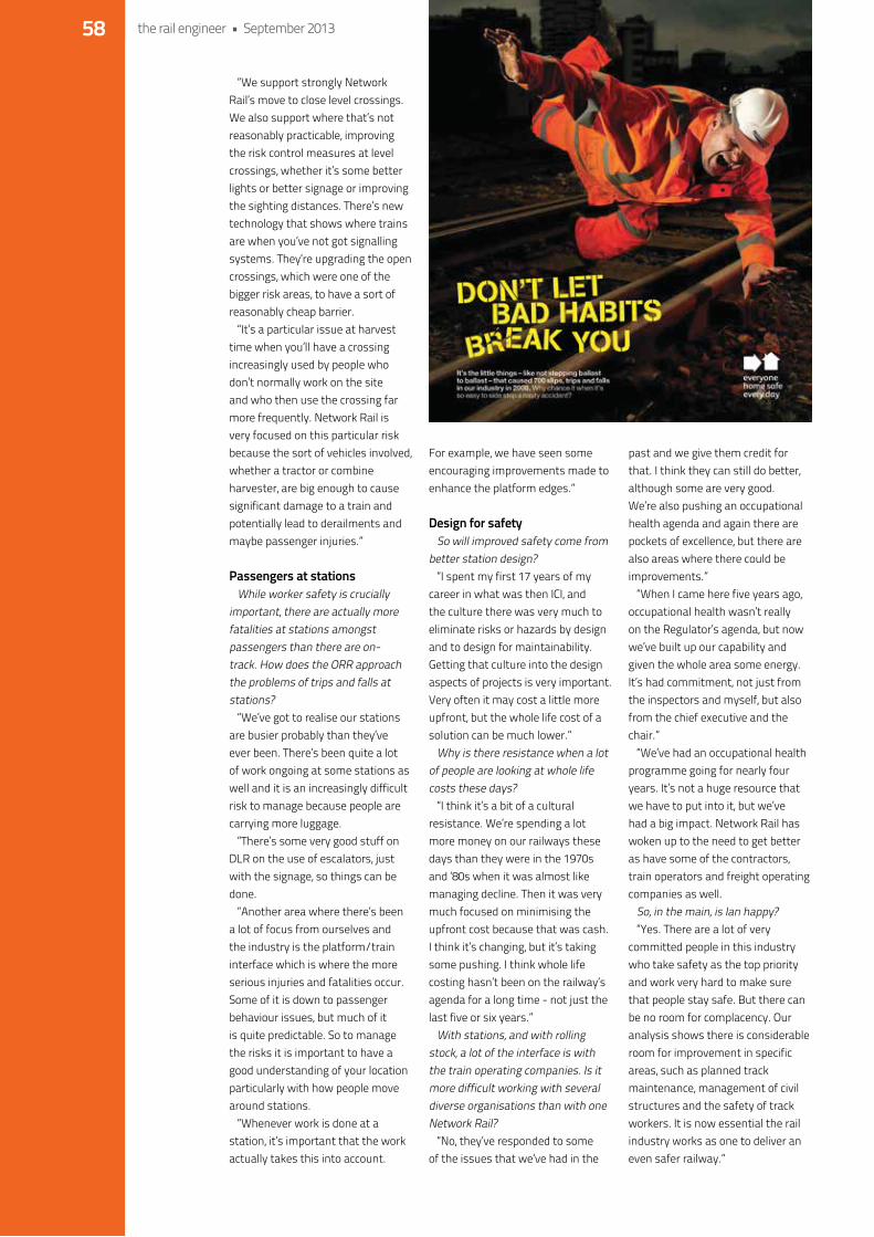
“We support strongly network Rail’s move to close level crossings. We also support where that’s not reasonably practicable, improving the risk control measures at level crossings, whether it’s some better lights or better signage or improving the sighting distances. There’s new technology that shows where trains are when you’ve not got signalling systems. They’re upgrading the open crossings, which were one of the bigger risk areas, to have a sort of reasonably cheap barrier.
“it’s a particular issue at harvest time when you’ll have a crossing increasingly used by people who don’t normally work on the site and who then use the crossing far more frequently. network Rail is very focused on this particular risk because the sort of vehicles involved, whether a tractor or combine harvester, are big enough to cause significant damage to a train and potentially lead to derailments and maybe passenger injuries.”
Passengers at stationsWhile worker safety is crucially
important, there are actually more fatalities at stations amongst passengers than there are on-track. how does the oRR approach the problems of trips and falls at stations?
“We’ve got to realise our stations are busier probably than they’ve ever been. There’s been quite a lot of work ongoing at some stations as well and it is an increasingly difficult risk to manage because people are carrying more luggage.
“There’s some very good stuff on dLR on the use of escalators, just with the signage, so things can be done.
“Another area where there’s been a lot of focus from ourselves and the industry is the platform/train interface which is where the more serious injuries and fatalities occur. Some of it is down to passenger behaviour issues, but much of it is quite predictable. So to manage the risks it is important to have a good understanding of your location particularly with how people move around stations.
“Whenever work is done at a station, it’s important that the work actually takes this into account.
For example, we have seen some encouraging improvements made to enhance the platform edges.”
design for safetySo will improved safety come from
better station design?“i spent my first 17 years of my
career in what was then iCi, and the culture there was very much to eliminate risks or hazards by design and to design for maintainability. Getting that culture into the design aspects of projects is very important. Very often it may cost a little more upfront, but the whole life cost of a solution can be much lower.”
Why is there resistance when a lot of people are looking at whole life costs these days?
“i think it’s a bit of a cultural resistance. We’re spending a lot more money on our railways these days than they were in the 1970s and ‘80s when it was almost like managing decline. Then it was very much focused on minimising the upfront cost because that was cash. i think it’s changing, but it’s taking some pushing. i think whole life costing hasn’t been on the railway’s agenda for a long time - not just the last five or six years.”
With stations, and with rolling stock, a lot of the interface is with the train operating companies. is it more difficult working with several diverse organisations than with one network Rail?
“no, they’ve responded to some of the issues that we’ve had in the
past and we give them credit for that. i think they can still do better, although some are very good. We’re also pushing an occupational health agenda and again there are pockets of excellence, but there are also areas where there could be improvements.”
“When i came here five years ago, occupational health wasn’t really on the Regulator’s agenda, but now we’ve built up our capability and given the whole area some energy. it’s had commitment, not just from the inspectors and myself, but also from the chief executive and the chair.”
“We’ve had an occupational health programme going for nearly four years. it’s not a huge resource that we have to put into it, but we’ve had a big impact. network Rail has woken up to the need to get better as have some of the contractors, train operators and freight operating companies as well.
So, in the main, is ian happy?“yes. There are a lot of very
committed people in this industry who take safety as the top priority and work very hard to make sure that people stay safe. But there can be no room for complacency. our analysis shows there is considerable room for improvement in specific areas, such as planned track maintenance, management of civil structures and the safety of track workers. it is now essential the rail industry works as one to deliver an even safer railway.”
the rail engineer • September 201358

It’s BACK...The HR, Recruitment & Skills Awards 2013
NOMINATIONS OPEN!Help us find the best:
Awards for Companies:
Awards for Teams:
Awards for Campaigns:
Awards for Individuals:
Best Executive Search company in Rail
Best Labour Supply Agency
Best Rail Professional Recruitment company
Best Training Organisation
Best Training Team
HR Team of the Year
Best New Entrant Programme / Campaign
Best People Strategy (Resourcing, Skills, HR)
Best Recruitment Campaign
HR Manager / Director of the Year
Outstanding Contribution to the Rail Industry
Trainer of the Year
Recruiter / HR Person of the Year
Nominate for free at
HR, RECRUITMENT& SKILLS AWARDS
Railway People
www.railhrawards.com
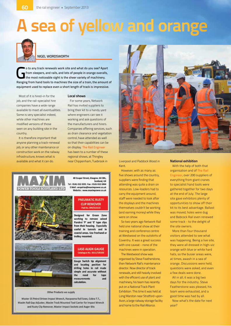
Go to any track renewals work site and what do you see? Apart from sleepers, and rails, and lots of people in orange overalls, the most noticeable sight is the sheer variety of machinery.
Ranging from hand tools to machines the size of a train, the amount of equipment used to replace even a short length of track is impressive.
Most of it is hired-in for the job, and the rail-specialist hire companies have a wide range available to meet all eventualities. Some is very specialist indeed, while other machines are modified versions of those seen on any building site in the country.
it is therefore important that anyone planning a track-renewal job, or any other maintenance or construction work on the railway infrastructure, knows what is available and what it can do.
local showsFor some years, network
Rail has invited suppliers to bring their kit to a handy yard where engineers can see it working and ask questions of the manufacturers and hirers. Companies offering services, such as drain clearance and vegetation control, have attended as well so that their capabilities can be on display. The Rail Engineer has been to a number of these regional shows, at Thingley near Chippenham, Tuebrook in Liverpool and Paddock Wood in
kent.however, with as many as
five shows around the country, suppliers were finding that attending was quite a drain on resources. Low-loaders had to carry the equipment around, staff were needed to look after the displays and the machines themselves couldn’t be working (and earning money) while they were on show.
So two years ago network Rail held one national show at their training and conference centre at Westwood on the outskirts of Coventry. it was a great success with one caveat - none of the machines were in operation.
The Westwood show was organised by Steve Featherstone, then network Rail’s maintenance director. now director of track renewals, and still heavily involved with the efficient use of plant and machinery, his team has recently put on a national Track Plant exhibition. This time it was held at Long Marston near Stratford-upon-Avon, a large railway storage facility and home to the Rail Alliance.
national exhibitionWith the help of both that
organisation and of The Rail Engineer, over 200 suppliers of everything from giant cranes to specialist hand tools were gathered together for two days at the end of July. The large site gave exhibitors plenty of opportunities to show off their kit to its best advantage. Ballast was moved, holes were dug and Babcock Rail even renewed some track - to the delight of the site owners.
More than four thousand visitors attended to see what was happening. Being a live site, they were all dressed in high-viz orange with blue or white hard hats, so the busier areas were, at times, awash in a sea of orange. discussions were held, questions were asked, and even a few deals were done.
All in all, it was a big two days for the industry. Steve Featherstone was pleased, his team were exhausted, and a good time was had by all.
now what’s the date for next year?
A sea of yellow and orangeNIGEL WORDSWORTH
the rail engineer • September 201360
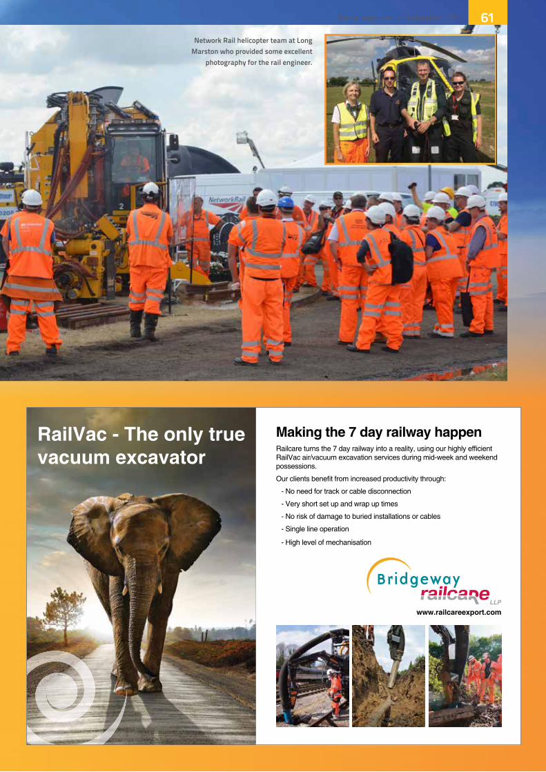
LLP
network rail helicopter team at long marston who provided some excellent
photography for the rail engineer.
the rail engineer • September 2013 61
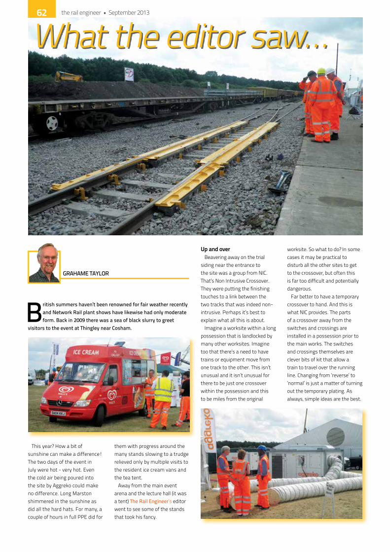
British summers haven’t been renowned for fair weather recently and Network Rail plant shows have likewise had only moderate form. Back in 2009 there was a sea of black slurry to greet
visitors to the event at Thingley near Cosham.
This year? how a bit of sunshine can make a difference! The two days of the event in July were hot - very hot. even the cold air being poured into the site by Aggreko could make no difference. Long Marston shimmered in the sunshine as did all the hard hats. For many, a couple of hours in full PPe did for
them with progress around the many stands slowing to a trudge relieved only by multiple visits to the resident ice cream vans and the tea tent.
Away from the main event arena and the lecture hall (it was a tent) The Rail Engineer’s editor went to see some of the stands that took his fancy.
up and overBeavering away on the trial
siding near the entrance to the site was a group from niC. That’s non intrusive Crossover. They were putting the finishing touches to a link between the two tracks that was indeed non-intrusive. Perhaps it’s best to explain what all this is about.
imagine a worksite within a long possession that is landlocked by many other worksites. imagine too that there’s a need to have trains or equipment move from one track to the other. This isn’t unusual and it isn’t unusual for there to be just one crossover within the possession and this to be miles from the original
worksite. So what to do? in some cases it may be practical to disturb all the other sites to get to the crossover, but often this is far too difficult and potentially dangerous.
Far better to have a temporary crossover to hand. And this is what niC provides. The parts of a crossover away from the switches and crossings are installed in a possession prior to the main works. The switches and crossings themselves are clever bits of kit that allow a train to travel over the running line. Changing from ‘reverse’ to ‘normal’ is just a matter of turning out the temporary plating. As always, simple ideas are the best.
What the editor saw…
GRAHAME TAYLOR
the rail engineer • September 201362


silence is goldenWalking along the main
exhibition roadway parallel to the trial track was like walking past any track renewal activity - pretty noisy. Multiple heavy machines, locomotives idling, voices, hammers - the usual things, but they suddenly seemed to disappear. how? Well Genwork had erected lengths of acoustic walling just two metres high and all was peace and quiet. not entirely of course. noise is subjective, but the difference was noticeable.
These panels are cleverly designed as single or double thickness modules. They’re hollow with a fill of ‘noise absorbing material’. one side has a perforated cover whilst the ‘public’ side is smooth and has been treated with a vandal resistant surface.
The panels are slotted into steel columns which are either set in the ground or bolted to concrete bases. This type of sound protection is really for permanent or semi-permanent sites. There are solutions involving temporary acoustic protection, which involve hanging what looks like a mattress to a scaffolding framework. Genwork is exploring this technology to enhance their range of products. As an aside it’s worth noting that one of the most powerful ways of reducing the public’s perception of noise is to say that noise protection is in place. Works wonders - for a while.
Plant pilesone supplier seemed to have
more plant than many on display. Some had seen quite a bit of action. Call it the patina of age. But there were brand new bits of elaborate kit with more to come showing how keltbray is convinced that investing in specialist rail plant is a prudent move. of the more obscure - specialist - pieces of kit were the machines involved in overhead electrification mast installation.
one road-rail machine can pick up a steel pile, manoeuvre it into position and vibrate it
down. Another had an hydraulic drop hammer to persuade any resistant pile to go just that little bit deeper. Continuing the acoustic reduction theme, there was a muffler to go round the pile to take out the worst of the noise.
serious toysWay over in the far, far corner
of the site were some busy little radio-controlled machines. They ranged in size from pretty small to rather large and they all had caterpillar tracks. it was all rather reminiscent of an afternoon in the local park with blokes playing with their model cars. But these were different and had a deadly serious purpose.
These machines were…..radio control slope mowers. not strictly lawnmowers as there weren’t any grass boxes to be seen. McMurtry of Gloucester specialises in this sort of kit and promotes it on the basis that it avoids personnel having to cut grass on steep banks when even a 10° slope can cause machines to slide or turn over.
Looking again at the area of field where these machines were showing their paces it was noticeably becoming more and more bald. They obviously work.
ups and downsAnd of course there has to be
a stairway to nowhere and this is what kwik-Step obligingly provided. The makeshift railway embankment had half a panel of track laid optimistically on a mixture of subsoil and tree roots, but nevertheless, in spite of this unpromising terrain, it was possible to climb to the top and admire the view. As always, though, the kwik-Step construction did the job without judging the material. it’s a clever system and, without the steps, the bank would have been impossible to climb. Point proven.
mystery objectRight, what do you reckon this
bit of kit is meant to do? There’s an oven, a flue pipe, it’s black and obviously very robust. But who would need a barbeque on such a
hot day? After all that’s just what it looks like.
it takes a bit of believing that this is in fact a track geometry measurement device - a high speed one at that. What, with a chimney? no, that’s where the GPS sensor is located. on the chimney. no, it’s a high speed track measurement device pioneered by Raildata BV of Utrecht… and it doesn’t have a chimney.
To be fair, this bit of kit standing on an anonymous bit of scaffolding in the middle of a hot field is a little difficult to identify. normally it sits on or near the buffer beam of a locomotive. The two angled barbeque legs shroud the beams from lasers located behind the oven doors. The laser beams pick up the running edges of the rails every 70mm when travelling at 140km/hr and fix the rail’s position in all three dimensions. once that’s done it’s up to clever software to filter out the movement of the train and then produce all the information normally associated with high speed recording.
After Long Marston, the next place this contraption will be spotted will be on the front of a
loco travelling between Wigan and Southport on a proof-of-concept run for network Rail.
Keeping in touchBut, and it’s a huge but, very
little of all this magic machinery and equipment is much use if people can’t talk to each other. Communication is vital and so probably two of the most important stands in the whole show - apart from the couple of ice cream vans - were those of high Motive and Site Link.
ok, they didn’t have machinery painted yellow and much of their kit can be carried in your pocket, but these are the guys who provide the vital links between machine and banksman, or between machine and machine, or between sites and their control offices. Communications are key to efficiency and to safety and so these understated companies should be right at the top of any list of suppliers.
Postlude By about 2pm on the Thursday
the heat was taking its toll. The crowds were still there - mainly in the tea tent and other hospitality venues - but the pace of life had slowed noticeably. kit was being packed away surreptitiously and the mowers had stopped mowing. There was no grass left. it was time for war stories and for exhibitors to meet their colleagues from other stands.
They hadn’t had time in the previous day and a half. PPe was returned to its boxes and visitors stood motionless in the blissful breeze before venturing into their oven-like cars. And the weather next year? don’t hold your breath!
the rail engineer • September 201364

Andrew Sumner
t. 01228 882 300e. [email protected]
Gary Newton
t. 01228 882 300e. [email protected]
Dave Richardson
t. 01228 882 300e. [email protected]
Rail Contracts Manager
Estimating Manager
Plant Manager
stobartrail.com
Rail Team of the year 2012
Stobart Rail owns and operates an extensive Stobart Rails own contracted works.
fleet of specialised plant that is available for
hire with or without operators on a nationwide Stobart Rail’s substantial fleet of road-rail
basis including road-rail equipment to match vehicles provides a comprehensive series of
the special requirements of operations on, or machine-to-trailer combinations, and also
near the permanent way. accommodates a host of highly specialised
attachments; ranging from tamping and
The Company has an extensive range of earth cabling equipment to ground investigation
moving, excavation and earth removal and soil nailing rigs.
vehicles, enabling Stobart Rail to tackle the
most demanding of tasks - this significant To enquire about hiring our plant for use on
investment is continually being added to and your next project (can include POL) or for our
upgraded and is predominantly used on most recent plant register contact:
Civil Engineering Projects & Nationwide Plant Hire

0370 050 0797www.aplant.com
Site Welfare& Power
Plant, Tools &Survey Equipment
all your equipment needs…...one company
Latest innovations from A-PlantA-Plant’s stand showcased its latest products including two of its award winning innovations - the Power Cube and Auto Tool Hire Unit. Very much one of the most talked-about items at the show, an A-Plant Power Cube (a portable, maintenance-free, self-contained energy pod) not only silently powered the A-Plant stand but one also powered the AmeyColas stand at the event.
Working in collaboration with its suppliers, the A-Plant stand really promoted the state-of-the-art equipment the company offers to the rail industry. other featured equipment included a welfare unit, Tufftrak floorcovering from A-Plant’s newly acquired company eve Trakway, lifting equipment from Probst, survey tools from Trimble and Topcon, cable locators from Cable detection, lighting from Ritelite and tools from Losomat Uk Ltd.
A-Plant’s business development director for rail, Paul Price, said of the show:
“We have a strong relationship with our suppliers and we wanted to demonstrate this by displaying some of the latest equipment in the market and in our fleet. The exhibition was highly focused - network
Rail gave us a great opportunity to engage with industry professionals and a chance to inform them of our service and equipment capabilities as well as answer any questions over the two-day event.”
» A-Plant
Winners at AquariusAquarius, the road-rail specialists, had a variety of vehicles on show at Long Marston, including the Rail Mule with an Ultra Light Trailer, a Rail Rover and a Road Rail Plant Trailer which were demonstrated on track; and the Weld Rover.
The team also gave away Aquarius tea breaks, served lots of tea, coffee and cooling drinks, talked non-stop, and went for a big lie down at the end!
Throughout the show, a slogan competition was held. There were two winners: “The Aquarius RRV is something that the heX Rail team is so proud of that it has gelled the team together to be a unit second to none!” (Mark Chestney, rail engineering manager, heathrow express)
“Quick to site, Rapid to work” (neil Moriarty, project manager at heathrow express)
They have both won a 4x4 experience day. Congratulations to them.
» Aquarius
the rail engineer • September 201366
Project1:Layout 1 19/8/13 12:28 Page 1
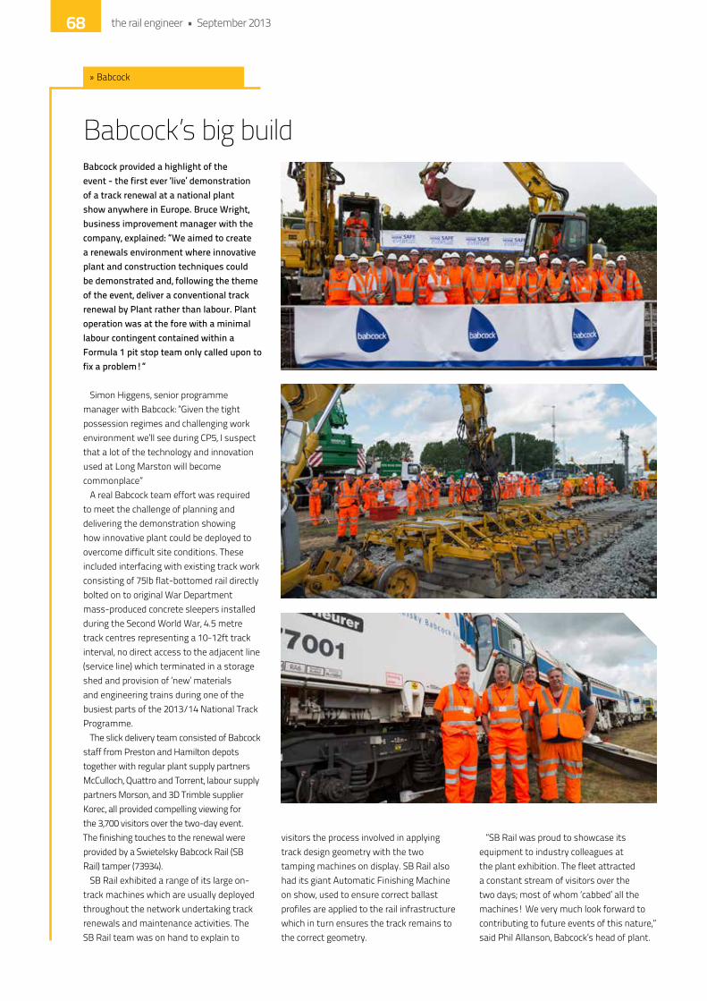
Babcock’s big buildBabcock provided a highlight of the event - the first ever ‘live’ demonstration of a track renewal at a national plant show anywhere in Europe. Bruce Wright, business improvement manager with the company, explained: “We aimed to create a renewals environment where innovative plant and construction techniques could be demonstrated and, following the theme of the event, deliver a conventional track renewal by Plant rather than labour. Plant operation was at the fore with a minimal labour contingent contained within a Formula 1 pit stop team only called upon to fix a problem!”
Simon higgens, senior programme manager with Babcock: “Given the tight possession regimes and challenging work environment we’ll see during CP5, i suspect that a lot of the technology and innovation used at Long Marston will become commonplace”
A real Babcock team effort was required to meet the challenge of planning and delivering the demonstration showing how innovative plant could be deployed to overcome difficult site conditions. These included interfacing with existing track work consisting of 75lb flat-bottomed rail directly bolted on to original War department mass-produced concrete sleepers installed during the Second World War, 4.5 metre track centres representing a 10-12ft track interval, no direct access to the adjacent line (service line) which terminated in a storage shed and provision of ‘new’ materials and engineering trains during one of the busiest parts of the 2013/14 national Track Programme.
The slick delivery team consisted of Babcock staff from Preston and hamilton depots together with regular plant supply partners McCulloch, Quattro and Torrent, labour supply partners Morson, and 3d Trimble supplier korec, all provided compelling viewing for the 3,700 visitors over the two-day event. The finishing touches to the renewal were provided by a Swietelsky Babcock Rail (SB Rail) tamper (73934).
SB Rail exhibited a range of its large on-track machines which are usually deployed throughout the network undertaking track renewals and maintenance activities. The SB Rail team was on hand to explain to
visitors the process involved in applying track design geometry with the two tamping machines on display. SB Rail also had its giant Automatic Finishing Machine on show, used to ensure correct ballast profiles are applied to the rail infrastructure which in turn ensures the track remains to the correct geometry.
“SB Rail was proud to showcase its equipment to industry colleagues at the plant exhibition. The fleet attracted a constant stream of visitors over the two days; most of whom ‘cabbed’ all the machines! We very much look forward to contributing to future events of this nature,” said Phil Allanson, Babcock’s head of plant.
» Babcock
the rail engineer • September 201368

Babcock International GroupKintail House3 Lister WayHamilton International ParkBlantyre G72 0FTUnited KingdomTelephone +44 (0)1698 203005Fax +44 (0)1698 203006Email [email protected]
www.babcockinternational.com/rail
Delighted to be Network Rail’s Supplier of the Year 2012
Babcock is a leading player in the UK rail infrastructure market. We provide track renewals, signalling, power, telecommunications, on-track plant, consultancy, training and integrated rail system solutions for our customers. We have built a reputation for delivering quality engineering projects by championing innovation and introducing new technologies into the rail industry, underpinned by the highest standards of safety.
Morris - new name, same WeldmakerMorris Site Machinery showed off its Weldmaker 165SP, which has been providing Network Rail with trackside welding power for the last 4 years. The machines are used every day for general fabrication, track welding and, with the ESAB BV1000, provide a cost effective solution to crossing and point replacement. The solution of using two ArcGen 165’s paralleled together and the ESAB BV1000 saves time, money and is more environmentally friendly as the old track is reused.
Tom Page, business development manager from Morris Site Machinery, said: “The national Plant Track exhibition was a great success. our robust range of quality products, dedication to product innovation, coupled with a commitment to customer service ensures we retain our market leading position within this sector.
“it was pleasing that so many of network
Rail’s welders and track engineers came onto the stand to comment on how pleased they were with the performance, quietness and reliability of our machines. We also had some positive feedback regarding our lighting towers and visitors to the
stand were interested in our new eco 90 Tower which offers a reduction of 80% fuel consumption over previous models and 185 hours single tank operation with the aid of a more fuel efficient engine and automatic start stop system.”
» Morris Site Machinery
www.morrismachinery.co.uk
Power in your hands
At Morris Site Machinery our mission is to bring the world’s best ligh�ng brands to your business.
Our SMC and So�lite ligh�ng solu�ons range from 8kg portable temporary ligh�ng kits to powerfulMetal Halide and LED ligh�ng towers to light any site.
Famously robust, offering the highest quality and always reliable, our top-class machines are only matched by our unparalleled service.
Call: 0845 409 0277 Email: [email protected]
the rail engineer • September 201370
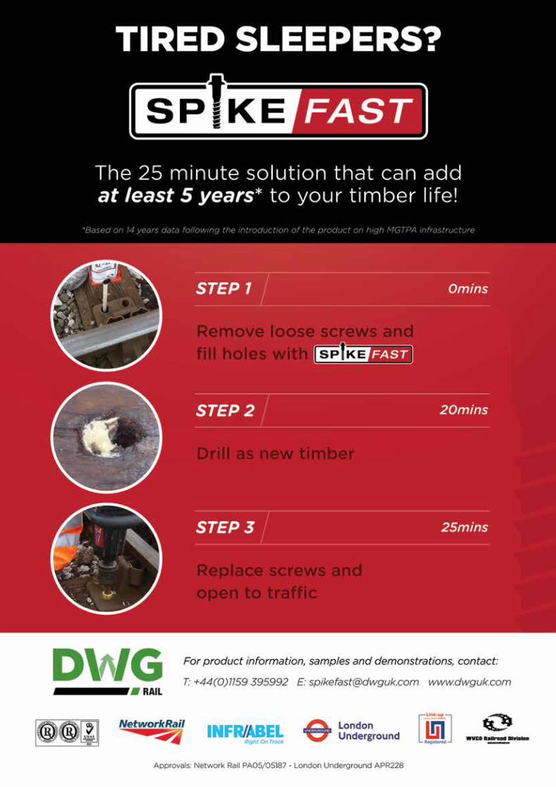

Brand new disc saw from CembreBuilding on its reputation for advantageous, high quality innovation in Rail tooling, Cembre showed off the very latest addition to its range with an ‘approval pending’ demonstration of the Robokatta RDS-14P, a new concept in Rail Disc Saws.
Robust, powerful and designed with a perfectly perpendicular action for precise cutting, the 2- stroke Robokatta is the world’s first Rail disc Saw offering both manual and automatic operation.
in manual mode, the support arm minimises the working weight of the machine for the operator, while in Automatic mode, the operator is in control, but away from the machine during the cutting phase, so experiences:
• Zero Vibration • Zero Physical Effort
• Zero Harmful Dust • Zero Sparks • Zero Exhaust Fumes • Minimum Acoustic Noise. Robokatta offers other
significant advantages over existing rail saws including ‘expert operator’ cutting times and accuracy through rigorously engineered components, patented systems and features designed for operator convenience; optimised disc performance to deliver more cuts; and enhanced operator security and visibility, improved motor protection and a
simplified disc change system. Cembre’s portfolio of market-
leading rail equipment also includes the world’s lightest Rail drill, Sleeper drills, impact
Wrenches and Pandrol Clip insertion/extraction Machines, along with our widely specified Rail electrical Connection and Tooling Systems.
Safeaid - quality, innovation and valueSafeaid’s star of the show was undoubtedly QuickBand, which is clearly a safer, simpler, smarter solution for armband wearers. New inserts are being added on a regular basis, and the flexibility and value that the system offers is proving a real hit with many rail companies.
The 3 key components of quality, innovation and value are reflected in the complete range of Safety equipment and PPe that Safeaid offers. And the 2 day event at Long Marston, with its relaxed and informal atmosphere, lent itself to some broad thinking. As a result, some great ideas came out, which are now being energetically pursued by the development team at Safeaid. one thing that became clear during the course of the exhibition is that the Rail industry needs innovation in order to help it deliver the value that is so essential to meet cost reduction targets.
» Safeaid
» Cembre
the rail engineer • September 201372
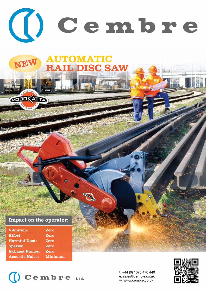
L t d.
t. +44 (0) 1675 470 440e. [email protected]. www.cembre.co.uk
Vibration: Zero
Effort: Zero
Harmful Dust: Zero
Sparks: Zero
Exhaust Fumes: Zero
Acoustic Noise: Minimum
Impact on the operator:
AUTOMATICRAIL DISC SAWNEW
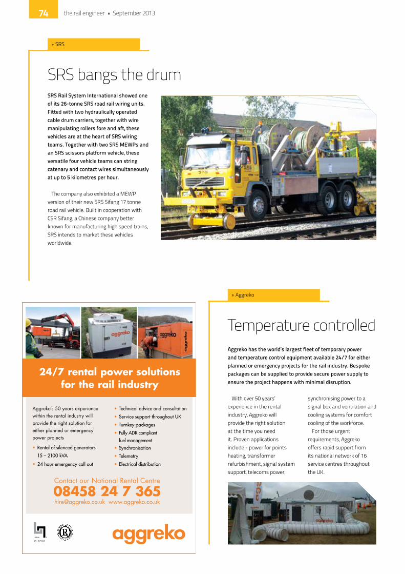
SRS bangs the drumSRS Rail System International showed one of its 26-tonne SRS road rail wiring units. Fitted with two hydraulically operated cable drum carriers, together with wire manipulating rollers fore and aft, these vehicles are at the heart of SRS wiring teams. Together with two SRS MEWPs and an SRS scissors platform vehicle, these versatile four vehicle teams can string catenary and contact wires simultaneously at up to 5 kilometres per hour.
The company also exhibited a MeWP version of their new SRS Sifang 17 tonne road rail vehicle. Built in cooperation with CSR Sifang, a Chinese company better known for manufacturing high speed trains, SRS intends to market these vehicles worldwide.
» SRS
Aggreko’s 50 years experience within the rental industry will provide the right solution for either planned or emergency power projects
ID: 17181
Contact our National Rental Centre
08458 24 7 365 [email protected] www.aggreko.co.uk
24/7 rental power solutions for the rail industry
Temperature controlledAggreko has the world’s largest fleet of temporary power and temperature control equipment available 24/7 for either planned or emergency projects for the rail industry. Bespoke packages can be supplied to provide secure power supply to ensure the project happens with minimal disruption.
With over 50 years’ experience in the rental industry, Aggreko will provide the right solution at the time you need it. Proven applications include - power for points heating, transformer refurbishment, signal system support, telecoms power,
synchronising power to a signal box and ventilation and cooling systems for comfort cooling of the workforce.
For those urgent requirements, Aggreko offers rapid support from its national network of 16 service centres throughout the Uk.
» Aggreko
the rail engineer • September 201374

ON THE ROADIN SAUDI ARABIA
An access vehicle on its way to workon the new Mecca Metro
MOUNTING TRACK IN THE UKMounting the track at a level crossing
takes 5 minutes and is possibleUNDER LIVE WIRES
INSPECTING BRIDGESIN IRELAND
An inspector has fullcontrol from the basket
DEPLOYED INSIDE THE ARCTIC CIRCLEAn SRS access vehicle working
on overhead lines in Sweden
LIFTING A SIGNAL GANTRYBEAM WITHOUT SLEWING
OVERHEAD LINES IN THE UKThe reverse knuckle joint between lower boom
and telescopic upper booms, coupled witha telescopic counterweight, allow the crane to
reach round the overhead lines. The heavy cranenecessitates an articulated design, thought to
be the fi rst ever articulated road rail vehicle
SRS ROAD RAIL LORRIESSERVING THE WORLD’S RAILWAYS
FOR ROAD RAIL AT ITS BEST CALL: 0044 (0)870 050 9253, EMAIL [email protected] VISIT OUR WEBSITE WWW.SRSRAILUK.COM
HIRING & SELLINGINTERNATIONALLY
A COMMERCIAL TRUCK ONTHE ROAD
A VERSATILE TOOL ON
THE TRACK

The UK’s favourite supplier of
Road Rail Maintenance Attachments
from; Richter & Muller, Cologne
and BSB, Berlin.
HSW combined Spot Re-sleeper /
Wet-Bed excavation attachment.
Visit our NEW website www.tastyplant.co.uk
or call 0845 677 4444
Colas - cranes, machines and a train namingColas Rail provided a number of live demonstrations with its 125-tonne rail-mounted Kirow crane lifting a locally stored tank wagon high into the air and the PEM/LEM machines demonstrating their unique capability to not only lift and move track panels and S&C units by rail but to “walk” these units when track is not available - amazing.
Two Track Relaying Machines (TRMs) demonstrated the excellent capabilities of these machines to remove and install track panels quickly and safely - a major contributor to optimised track renewals.
The expert team from Colas Rail was on hand to explain the capabilities and process of the equipment and how this would enhance the ability to accomplish track renewals safely, effectively saving time and cost whilst improving quality.
Colas Rail actively supported the live track renewals demonstration by providing a Class 66 locomotive to accomplish the
haulage for the supply of materials and removal of spoil to and from the work site. This locomotive haulage service is a significant addition to the track renewals and large plant capabilities of Colas Rail to provide a total start to finish Track Renewals capability.
one of the Colas Rail fleet, locomotive
66850, was named “david Maidment oBe” at the show. This is in recognition of the amazing work that david has provided since he formed the Railway Children charity. There was genuine surprise and pleasure on david’s face when he pulled back the curtain to see his name on the side of the locomotive - a real accolade.
» Colas Rail
Hydraulic attachmentsTasty Plant combined with Terock for the National Track Plant Show, and this resulted in a very successful two days for hydraulic attachments. There was a refreshing air of optimism around that was almost palpable and, subsequent to the show, a number of enquiries were received for multiple orders. These are being worked on, and should come to a successful conclusion shortly.
director ian McMeekin commented: “We were very pleased to be asked to attend and also very pleased to meet and have an open discussion with Steve Featherstone, network Rail director. due to his transparent approach, we feel that the whole industry is becoming a more accessible place to work in. People are more communicative and want to get on. network Rail, consequently, have a far better understanding now than at any time in the
recent few years on exactly what life can be like in the supply chain. onwards and upwards!”
» Tasty plant
the rail engineer • September 201376
Mar10 Advert 2/5/12 09:17 Page 1

Variety from Balfour Beatty RailBalfour Beatty Rail showcased its extensive range of on-track machines at the event, from the Kirow KRC1200 to the Plasser and Theurer Track Relayer. Plant innovations included the high performance Front Shovel Excavator which offers unrivalled top stone rehandling capability, the Base Ballast Bopper and the Top Stone Topper units which provide efficient, safe placement of ballast during track renewals, and the Universal Rail Thimble - an effective tool for supporting and manipulating long welded rail.
Constantly developing its existing plant to improve safety, sustainability and reliability, Balfour Beatty Rail was keen to share some of its ideas at the two-day event. This included a demonstration of a new hydraulic oil Leak detection and Vacuum Leak Reduction System (hoLd-VLRS) for hydraulic oil reservoirs capable of detecting a change in oil level of one litre and creating a vacuum in the hydraulic system which will prevent any further oil loss.
Visitors had the opportunity to see some of Balfour Beatty Rail’s plant in action and to consult with the company’s on-site experts concerning new innovative ways of working.
The innovative ‘Mission Room’ technology, which was recently awarded this year’s Safety Award at the network Rail Partnership Awards, was also demonstrated on the Balfour Beatty Rail stand. The system, which was first introduced to the rail industry on the Finsbury Park to Alexandra Palace project (delivered by a network Rail / Balfour Beatty Rail alliance) provides virtual access to sites, significantly reducing the need for many costly and hazardous real site visits.
Geoff Brown, Balfour Beatty’s engineering and development Manager, praised the event saying “We have been waiting a long time to take part in a plant innovation event such as this and we experienced a good level of interest especially in the more bespoke areas of our expertise. We are already planning for the next one.”
» Balfour Beatty Rail
the rail engineer • September 201378

Registered
Compact and Lightweight at just 3.81kg
Wide area of illumination
Mast extends above 1.5 metres
Deploys rapidly
Silent running
Ideal for remote locations
The Peli™ 9420 RechargeableLED Worklight
Peli Products (UK) LtdTel: 01457 869999 www.peliproducts.co.uk
Peli makes light work of itPeli’s 9420 work light is ideal for rapid response, it is easy to carry and can be set up very quickly. As the lightest in its class, there was a great deal of interest at the recent Network Rail Plant show.
ideal for signals and telecoms engineers, the 9420 weighs only 3.81kg and is particularly suited to remote or difficult to access locations. offering instant, silent illumination, the 9420 is compact and portable, folding down to just 74cm long. The mast extends above 1.5 metres allowing a wide area of illumination.
The 9420 has a unique feature in this range - the battery pack can be charged independently of the lighting system.
There are 2 versions - standard and XL - the latter includes a blow moulded case, shoulder strap and two battery packs so one can be on charge while the other is in situ with the system in use.
Peli area lights offer powerful,
rechargeable, Led lighting - a safe, economic and convenient alternative to generator powered units. With silent
operation and no trailing cables to create a trip hazard, they are ideally suited to the rail industry.
» Peli
the rail engineer • September 2013 79
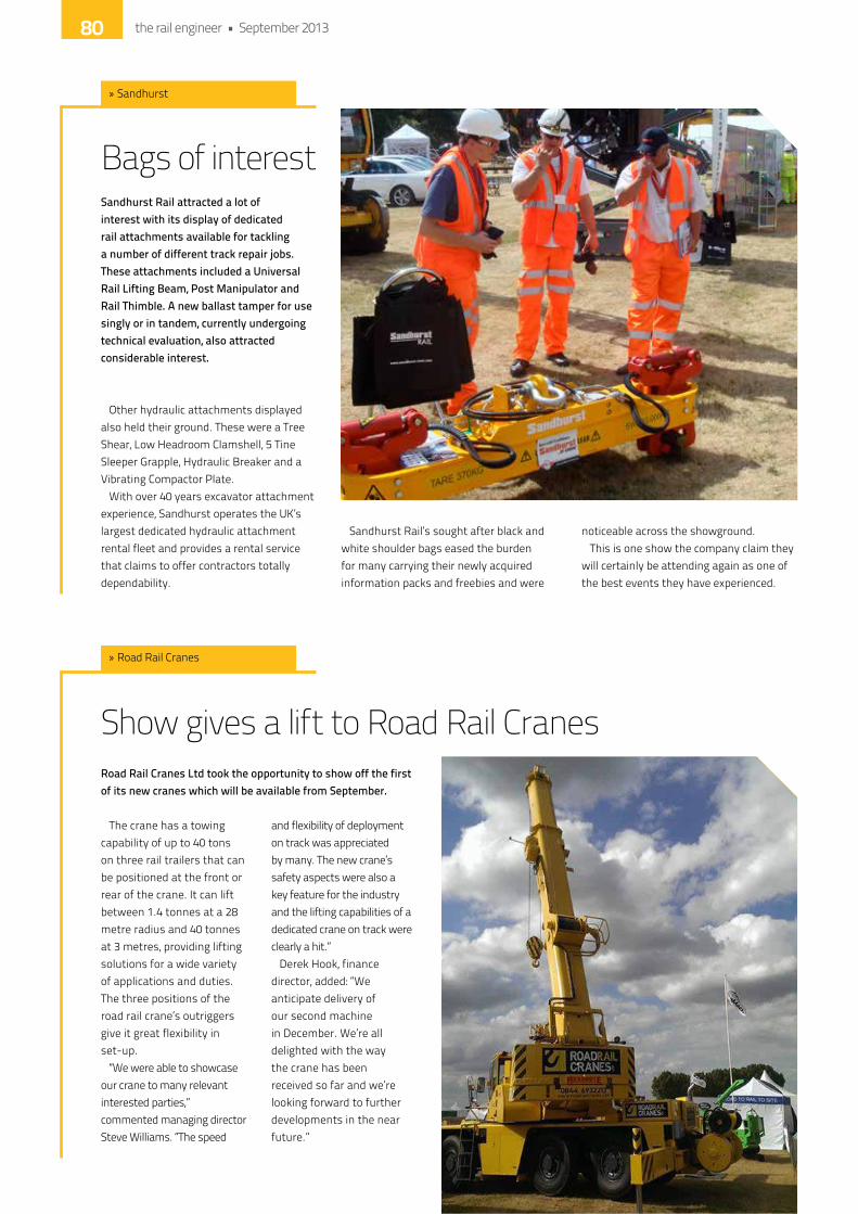
Bags of interestSandhurst Rail attracted a lot of interest with its display of dedicated rail attachments available for tackling a number of different track repair jobs. These attachments included a Universal Rail Lifting Beam, Post Manipulator and Rail Thimble. A new ballast tamper for use singly or in tandem, currently undergoing technical evaluation, also attracted considerable interest.
other hydraulic attachments displayed also held their ground. These were a Tree Shear, Low headroom Clamshell, 5 Tine Sleeper Grapple, hydraulic Breaker and a Vibrating Compactor Plate.
With over 40 years excavator attachment experience, Sandhurst operates the Uk’s largest dedicated hydraulic attachment rental fleet and provides a rental service that claims to offer contractors totally dependability.
Sandhurst Rail’s sought after black and white shoulder bags eased the burden for many carrying their newly acquired information packs and freebies and were
noticeable across the showground.This is one show the company claim they
will certainly be attending again as one of the best events they have experienced.
Show gives a lift to Road Rail CranesRoad Rail Cranes Ltd took the opportunity to show off the first of its new cranes which will be available from September.
The crane has a towing capability of up to 40 tons on three rail trailers that can be positioned at the front or rear of the crane. it can lift between 1.4 tonnes at a 28 metre radius and 40 tonnes at 3 metres, providing lifting solutions for a wide variety of applications and duties. The three positions of the road rail crane’s outriggers give it great flexibility in set-up.
“We were able to showcase our crane to many relevant interested parties,” commented managing director Steve Williams. “The speed
and flexibility of deployment on track was appreciated by many. The new crane’s safety aspects were also a key feature for the industry and the lifting capabilities of a dedicated crane on track were clearly a hit.”
derek hook, finance director, added: “We anticipate delivery of our second machine in december. We’re all delighted with the way the crane has been received so far and we’re looking forward to further developments in the near future.”
» Road Rail Cranes
» Sandhurst
the rail engineer • September 201380

RailwayPeople.comFast track your career
...awaiting your application.
over
live jobs
2,000
As the market leader in the supply of
control panels and pushbuttons, we
are looking for a Technical Sales
Engineer to help us maintain our
number one position in the rail market.
You will be visiting customers across the country, supporting
their needs, providing technical solutions and commercial
proposals, assisted by our expert team. With an Electro and
Mechanical qualification – minimum to Level 3 and a good
knowledge of the UK rail market; CAD experience an
advantage.
Package, including car, pension and private health.
Apply with your CV to Gill Stafford, EAO Ltd., Highland House,
Albert Drive, Burgess Hill. RH15 9TN [email protected]
Closing date for applications 20 September 2013
Technical Sales EngineerNationwide
www.eao.com
www.trsstaffing.com
Rail and Infrastructure VacanciesTRS Staffing Solutions are international engineering recruitment specialists. We recruit for major National and International projects for leading National Rail organisations, main contractors and consultancies. Currently we have vacancies for the following:
+44 (0)20 7419 5800 or email [email protected]
Please send your CV or if you’d prefer to discuss a role in more detail and in condence, please contact one of our specialist consultants on
Rail, Infrastructure & Construction
Signal Design Project Engineer (Signalling & Telecoms)London - £350 - 500/dayMainline Project Experience, IRSE Licence or relevant signalling experience
Cost EngineersLondon- £35 - 60K or £300 - 400/day Utilities, Airport or Rail experience with a Civils background
Rail Project Managers, Site Agent & Sub-AgentsRegional- £35 - 55K or £250 - 400/dayExperience on rail Civils works – Bridge refurbishments, embankments and Earthworks
P3e PlannersLondon, Swindon & Midlands - £300 – 400/dayExperience of Network Rail projects, Primavera experience essential
E&P/OLE EngineersLondon/Manchester/Birmingham - £35 - 60K or £350 - 500/dayWorking on major new projects
Principal & Senior Civil/Structural Design Engineers - CRELondon, Manchester, Warrington & York - £40 - 60K or £350 - 450/day Rail experience including station, platform & bridge designs
the rail engineer • September 2013RECRUITMENT 81

For further information, or to make an application:Tel: 01923 635089 email: [email protected]
a Balfour Beatty and Alstom company
All the above positions have the following benefits: We offer a competitive salary plus a range of benefits including a contributory pension and 25 days holiday.
Signalling Solutions is a company formed by combining the complementary signalling resources
and products of Alstom Transport Information Solutions UK and Balfour Beatty Rail Projects.
If you are looking for a new challenge and want to make a real contribution to the success of our
business, we have opportunities in the following disciplines:
• Design • Testing
• Planning • Project Management
• Administration • Quantity Surveying
• Installation Management • Project Engineering
• Health, Safety and Environmental • Systems Engineering
If you want to work with a forward thinking company and the latest cutting edge technology,
apply today. In return for your commitment and contribution, you can expect an excellent
package and the opportunity to shape your career the way that you want, with training,
development and career planning.
For more information please visit www.signallingsolutions.com or apply by sending your CV to
We’re going places.Join us in Bristol.


UK Power Networks Services is a leading provider of electrical infrastructure with signifi cant experience of working on high profi le transport projects such as High Speed 1, High Speed 2 and Crossrail.
Infl uencing your energy strategies with integrated solutions
Contact us by visiting: www.ukpowernetworksservices.co.uk
Consulting | Technologies | Engineering | Construction | Operation & Maintenance | Finance
UK Power Networks Services:• Consistently delivers results on the most challenging projects • Can undertake the total requirements of any strategic infrastructure project • Has access to a wealth of international experience in providing fi nance solutions
8137_ UKPNS Rail_AW.indd 1 08/01/2013 10:20