the refractor/phoropter— an important tool in vision...
TRANSCRIPT
Copyright © 2010 Douglas A. Kerr. May be reproduced and/or distributed but only intact, including this notice. Brief excerpts may be reproduced with credit.
The Refractor/Phoropter— An Important Tool in Vision Correction
Douglas A. Kerr
Issue 3 December 7, 2010
ABSTRACT
In the field of vision care, refractor refers to an instrument (sometimes called a phoropter, although Phoropter is a tradename) used to examine a patient to determine the optimum properties of corrective lenses used to overcome various deficiencies in his vision.
In this article we describe the traditional “manual” form of this instrument and the basic way in which it is used.
Since corrective lenses are the heart of the overall activity here, we begin with a review of some principles of lens theory.
Next we consider the notation by which the properties of an eyeglass lens are specified in a “prescription”. We also look into the fact that a given lens can have its properties stated in two different, but equivalent ways, each used in separate branches of the eye care profession a matter that will have an affect on the design details of the refractors to be used in those two contexts.
An appendix discusses in detail one ingenious part of a manual refractor, the Jackson cross cylinder, used to optimize the parameters for astigmatism correction. A second appendix reviews how the power of a cylindrical lens in a certain direction varies with the angle of that direction with respect to the axis of the lens.
CAVEAT
I am not an eye care professional, nor do I have any formal training in the practice in that field nor in its own unique branch of optical science. The information in this article is my own interpretation of the results of extensive (mostly quite recent) research into the available literature, through the prism of my own scientific and engineering background and outlook.
Optical Principles of Eyeglass Prescriptions Page 2
INTRODUCTION
A manual refractor is the “mask-like” instrument used by ophthalmologists and optometrists to test the refractive behavior of eyes and determine the optimal parameters of corrective lenses.
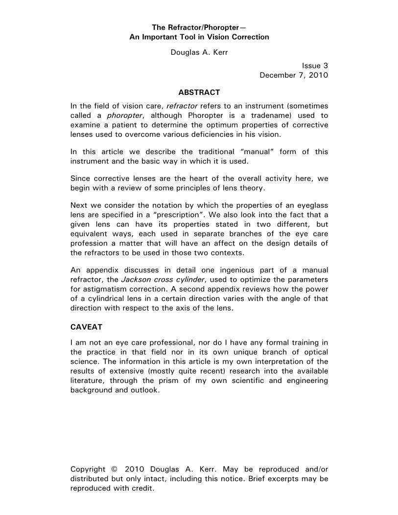
In figure 1 we see a U.S. Navy unit, on shipboard (apparently a Burton Model 7500-1). As seen here, it would make a nice Halloween costume.
Figure 1. Manual refractor (phoropter) (Burton 7500-1) PD—US Navy Photograph via Wikimedia Commons
Annotations by this author
The instrument is often called a phoropter, the original name given the instrument by its inventor, although today Phoropter is actually a trademark of one manufacturer for their line of manual refractors1.
A manual refractor is essentially an eyeglass simulator. It allows the vision care professional to establish the same optical properties as would a pair of eyeglass lenses, changing them in order to determine what parameters produce the best result to the subject.
Before I continue with the description of this instrument, how it operates, and how it is used, I will provide some basic background in pertinent areas.
1 Reichert Technologies, who acquired the trademark from American Optical, who acquired it from the firm of Henry L. De Zeng, generally recognized as the inventor of the instrument, in about 1928, who coined the term “phoropter”. Leica is also in the trademark trail in some way.
Optical Principles of Eyeglass Prescriptions Page 3
LENSES
Lens refractive power
The refractive power (“power”) of a lens is the degree to which it will converge (or diverge) rays of light emanating from the same point on an object and entering the lens at different points on its face.
Quantitatively, in normal optical technical work, the power of a lens is defined as the reciprocal of its focal length. The traditional unit of power is the inverse meter (m-1), alternately called diopter (symbol D)2. A lens with a power of one diopter has a focal length of one meter.
In connection with ophthalmic (vision correction) lenses, a different definition of power is used from the one most often found in general optical work. It is called the vertex power. An explanation of this, and why it is used in connection with ophthalmic (vision correction) lenses is covered in Appendix A.
Spherical lenses
In ophthalmic work, a spherical lens is any lens that has rotational symmetry, whether or not its surface is actually a portion of the sphere. Thus we can (and often do) have aspherical spherical lenses.
A converging lens (which has a positive focal length) has a positive power. A diverging lens (which has a negative focal length) has a negative power. A spherical lens exhibits the same power along any direction.
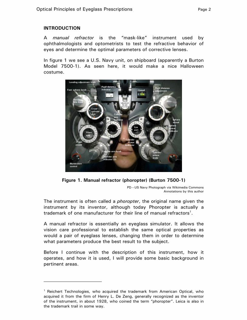
We can present the variation (if any) in the refractive power of a lens with direction on a polar chart. In figure 2, panel A, we see a plot of a spherical lens with refractive power +1.0 D (a converging lens).
Spherical lens(refractive power+1.00 diopter)
90°
180° 0°
Spherical lens(refractive power -0.50 diopter)
90°
180° 0°
A B
0.2
0.5
0.7
1.0
1.2
1.5
0.2
0.5
0.7
1.0
1.2
1.5
Figure 2. Spherical lens—power plot
2 The unit diopter is the one always used in optometric and ophthalmic practice.
Optical Principles of Eyeglass Prescriptions Page 4
This is a trivial case, and hardly requires a chart to explain. But we show the plot here to establish the format and notation.
The radius to the curve in a certain direction indicates the refractive power (in diopters) for that direction. Recall that a “direction” here means both ways: either way along the line at a certain angle. Because of that symmetry, we only need to plot half the curve. But I show the curve for a full 360° for aesthetic completeness.
In this field, the usual scientific convention is followed, with the angle reference (0°) being to the right (but there is a wrinkle, about which more shortly).
It is difficult to express negative values on a chart in polar coordinates—a “negative” radius would put the point on the opposite side of the chart, where it would just look like the (positive) value for an angle 180° from the actual angle.
To escape this difficulty, here I will plot negative values of the refractive power as a dotted line. And we see that in figure 22, panel B, the plot for a spherical lens with a refractive power of -0.5 D (a diverging lens).
Cylindrical lenses
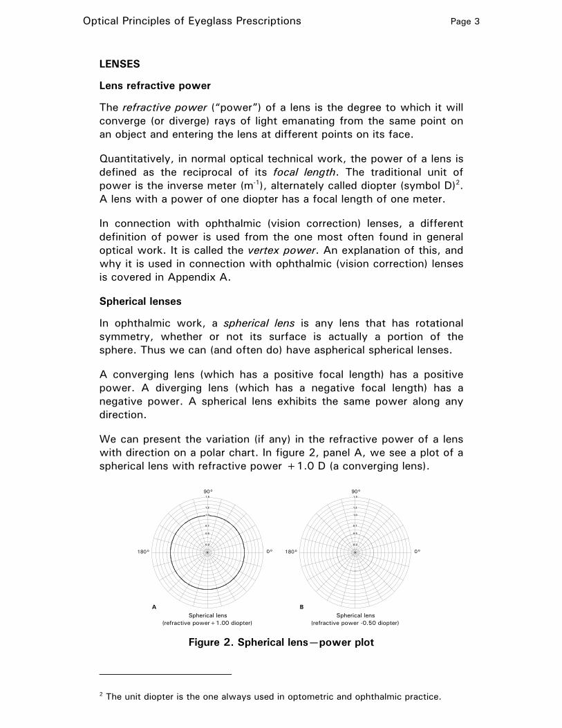
A cylindrical lens has a surface that is a portion of a cylinder (which may or may not be exactly a circular cylinder). A cylindrical lens exhibits a certain power (its “rated” power) in one direction (perpendicular to its axis). Along its axis, it exhibits zero power. At intermediate angles, it exhibits intermediate values of power.
cylinderaxis
(0°, butcalled180°)
90°
Cylindrical lens(refractive power+1.00 diopter, axis "180°")
180°0°
cylinderaxis
(30°)
90°
Cylindrical lens(refractive power -0.50 diopter, axis 30°)
0°
1.5
A B
0.2
0.5
0.7
1.0
1.2
1.5
0.2
0.5
0.7
1.0
1.2
1.5
Figure 3. Cylindrical lens—power plot
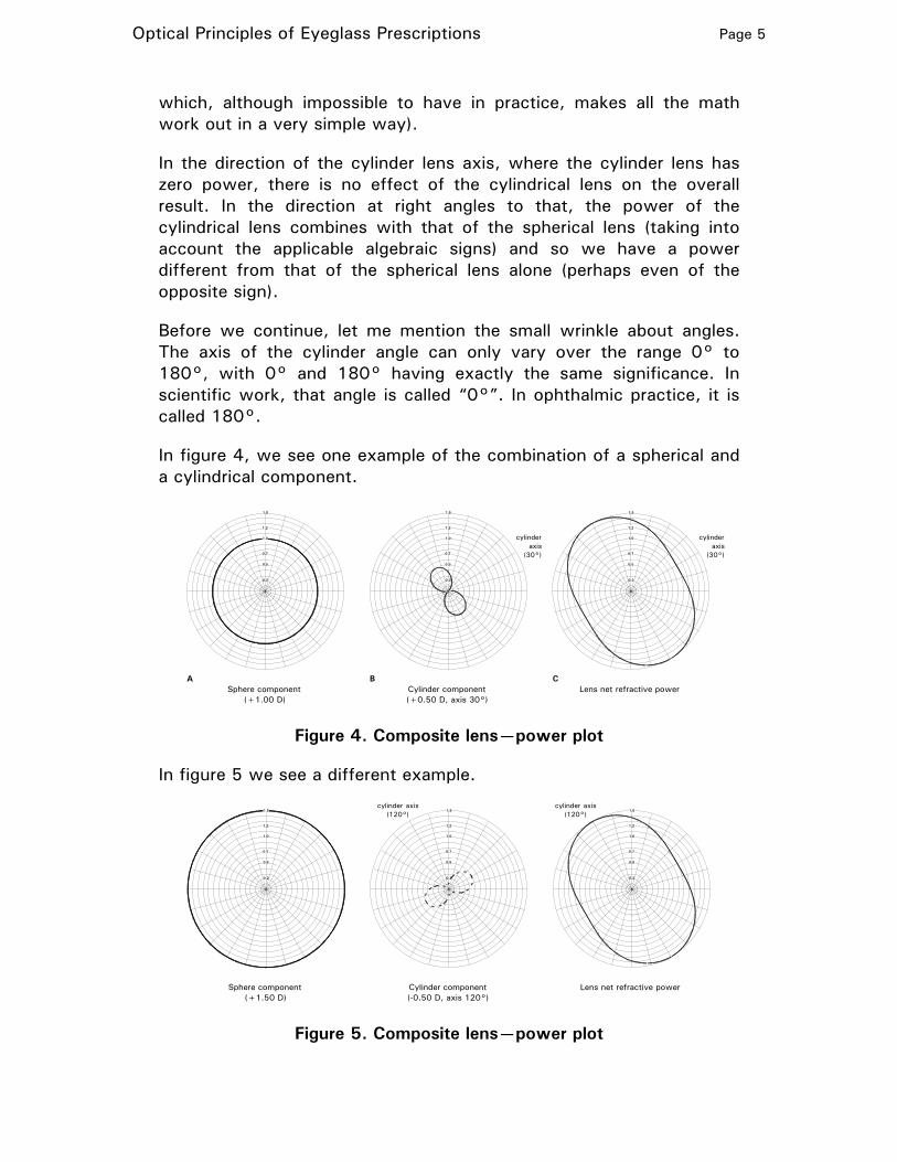
We see this illustrated in figure 3 for two cylindrical lenses, one with a positive power and one with a negative power.
Imagine that we combine a spherical lens and a cylindrical lens (and we assume here the convenience of the fanciful “thin lens” conceit,
Optical Principles of Eyeglass Prescriptions Page 5
which, although impossible to have in practice, makes all the math work out in a very simple way).
In the direction of the cylinder lens axis, where the cylinder lens has zero power, there is no effect of the cylindrical lens on the overall result. In the direction at right angles to that, the power of the cylindrical lens combines with that of the spherical lens (taking into account the applicable algebraic signs) and so we have a power different from that of the spherical lens alone (perhaps even of the opposite sign).
Before we continue, let me mention the small wrinkle about angles. The axis of the cylinder angle can only vary over the range 0° to 180°, with 0° and 180° having exactly the same significance. In scientific work, that angle is called “0°”. In ophthalmic practice, it is called 180°.
In figure 4, we see one example of the combination of a spherical and a cylindrical component.
cylinderaxis
(30°)
cylinderaxis
(30°)
Cylinder component(+0.50 D, axis 30°)
Sphere component(+1.00 D)
A B C
0.2
0.5
0.7
1.2
1.5
0.2
0.5
0.7
1.0
1.2
1.5
0.2
0.5
0.7
1.0
1.2
1.5
1.0
Lens net refractive power
Figure 4. Composite lens—power plot
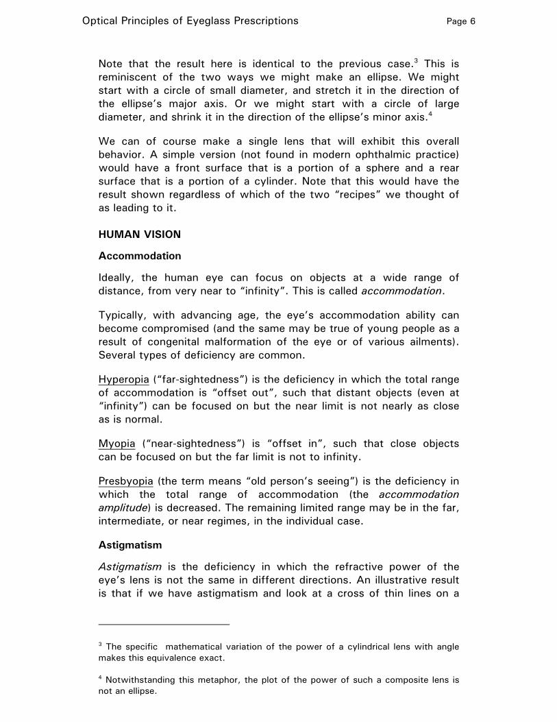
In figure 5 we see a different example.
cylinder axis(120°)
Cylinder component(-0.50 D, axis 120°)
Sphere component(+1.50 D)
Lens net refractive power
cylinder axis(120°)
0.2
0.5
0.7
1.0
1.2
0.2
0.5
0.7
1.0
1.2
1.5
0.2
0.5
0.7
1.0
1.2
1.51.5
Figure 5. Composite lens—power plot
Optical Principles of Eyeglass Prescriptions Page 6
Note that the result here is identical to the previous case.3 This is reminiscent of the two ways we might make an ellipse. We might start with a circle of small diameter, and stretch it in the direction of the ellipse’s major axis. Or we might start with a circle of large diameter, and shrink it in the direction of the ellipse’s minor axis.4
We can of course make a single lens that will exhibit this overall behavior. A simple version (not found in modern ophthalmic practice) would have a front surface that is a portion of a sphere and a rear surface that is a portion of a cylinder. Note that this would have the result shown regardless of which of the two “recipes” we thought of as leading to it.
HUMAN VISION
Accommodation
Ideally, the human eye can focus on objects at a wide range of distance, from very near to “infinity”. This is called accommodation.
Typically, with advancing age, the eye’s accommodation ability can become compromised (and the same may be true of young people as a result of congenital malformation of the eye or of various ailments). Several types of deficiency are common.
Hyperopia (“far-sightedness”) is the deficiency in which the total range of accommodation is “offset out”, such that distant objects (even at “infinity”) can be focused on but the near limit is not nearly as close as is normal.
Myopia (“near-sightedness”) is “offset in”, such that close objects can be focused on but the far limit is not to infinity.
Presbyopia (the term means “old person’s seeing”) is the deficiency in which the total range of accommodation (the accommodation amplitude) is decreased. The remaining limited range may be in the far, intermediate, or near regimes, in the individual case.
Astigmatism
Astigmatism is the deficiency in which the refractive power of the eye’s lens is not the same in different directions. An illustrative result is that if we have astigmatism and look at a cross of thin lines on a
3 The specific mathematical variation of the power of a cylindrical lens with angle makes this equivalence exact.
4 Notwithstanding this metaphor, the plot of the power of such a composite lens is not an ellipse.
Optical Principles of Eyeglass Prescriptions Page 7
card, we can focus so that the vertical line is sharp, or the horizontal line is sharp, but not both at the same time.
Correction with lenses
We can overcome basic deficiencies in accommodation with the use of a corrective lens. For farsightedness, we can use a (spherical) corrective lens with a positive power; this will shift the range of focus in the “nearer” direction. For nearsightedness, we can use a (spherical) corrective lens with a negative power; this will shift the range of focus in the “farther” direction.
We can overcome astigmatism with the use of a cylindrical lens.
Not surprisingly, in typical cases, both “spherical” and “cylindrical” components are combined to deal with the overall visual syndrome.
THE PRESCRIPTION
General
An eyeglass prescription is a specification for the lenses in the glasses. It is done in terms of the model we saw above, in which the overall refractive pattern of the lens is described in terms of the joint effect of two hypothetical lenses, one spherical and one (only present if there is a correction for astigmatism) cylindrical.
Recall that, as we saw in figures 4 and 5, the identical lens result can be conceptually implemented with either of two conceptual “recipes”; for that particular example, we could combine:
• A spherical lens with power +1.00 D
• A cylindrical lens with power +0.50 D and axis 30°
or
• A spherical lens with power +1.50 D
• A cylindrical lens with power –0.50 D and axis 120°
Recall that in reality the way the lens is actually made may not directly follow either of those “recipes”.
Two systems of notation
Either model could be used (at our choice) as the premise for defining the desired result in a prescription. It turns out that when the prescription is written by an ophthalmologist (a physician and surgeon specializing in the eyes), it would be in the first form (the cylinder component always being with a positive power), called the “positive cylinder” form.
Optical Principles of Eyeglass Prescriptions Page 8
When the prescription is written by an optometrist (a Doctor of Optometry, qualified and certified to examine eyes and issue eyeglass prescriptions), it would be in the second form, (the cylinder component always being with a negative power), called the “negative cylinder” form.
This is not only the result of accidental historical “diversity”. It is claimed that, when determining the optimal prescription for corrective lenses, initially using combinations of “trial” lenses, or later using a refractor, the pragmatic strategy used in searching for the best combination plays out better under one scheme for stating the final result than for the other. But of course, two camps claim that such reasoning leads to the two different schemes as best.
Format of the prescription
In a prescription, there is a line (or section) for each eye. In each, for single-vision eyeglasses (not bifocals), there are three parameters stated:
• The power of the spherical component (could be zero). This is normally in increments of 0.25 D.
If there is a cylindrical component:
• Its power (normally in increments of 0.25 D)
• The angle of its cylinder axis (normally in increments of 5°, from 5° through 180°.
Often, the indicators OD (from the Latin, oculus dexter) and OS (oculus sinister) are used for the right and left eyes, respectively. (OU—oculus uterque—indicates both eyes.)
We will give our first complete example in the “positive cylinder” system.
There a complete prescription might look like this:
OD +1.25 +0.50 X 130
OS +1.50 +0.75 X 25
Sometimes the decimal points are omitted (and all powers stated to two decimal places), so it would look like this:
OD +125 +050 X 130
OS +150 +075 X 25
There are many other variations in style.
For the very same pair of lenses, under the “negative cylinder” system, the prescription might look like this:
Optical Principles of Eyeglass Prescriptions Page 9
OD +1.75 –0.50 X 40
OS +2.25 –0.75 X 115
BACK TO THE REFRACTOR
Basic concept
As I mentioned at the outset, a manual refractor is essentially an eyeglass simulator. It allows the examiner to establish the same optical properties as would a pair of eyeglass lenses, changing them in order to determine what parameters produce the best result to the subject.
On each eye unit, a large wheel puts into place one of a number of spherical lenses,5 with different powers, resulting in a net power variable over a large range in steps of 0.25 diopters. Both positive and negative powers are provided, on both sides of a “zero-power” position, although not usually symmetrically (for example, a range of -19.00 D through +16.75 D, 144 values in all). The power in effect is indicated in a little window, the markings in black for positive powers and red for negative (zero gets both).
A knob then puts in place one of a number of cylinder lenses,6 with powers differing in steps of 0.25 D. Again, the power in effect shows in another little window. Another knob rotates all the cylinder lenses so as to vary the angle of the cylinder axis of the lens in place (the rest of them, too, but this doesn’t do anything).
We might expect that the cylinder power knob would put in place a range of cylinder lenses with both positive and negative powers, with a “zero” in between.
But of course, as we saw above, there is no need for that—the job can be done with only positive, or maybe negative, cylinder powers. Taking advantage of that, the instrument only has cylinder lenses of one sign (plus the zero, of course). But which sign?
5 Actually, two lenses, on two different disks, are “stacked” for each setting. Typically, the ones on one disk vary in steps of 0.25 D, and those in the other vary in steps of 3.00 D. The wheel moves the 0.25 D disk, and after 12 steps, the 3.00 D moves one step. Often there is a knob to “bump” the 3.00 D disk to hustle through the range.
6 Again, two lenses, on two different disks, are “stacked” for each setting. Typically, the ones on one disk vary in steps of 0.25 D, and those in the other vary in steps of 1.25 diopter.
Optical Principles of Eyeglass Prescriptions Page 10
Well, each model is made in two versions. For the ones sold to ophthalmologists, the repertoire of cylinder lenses all have positive powers (the “positive cylinder” version). For those sold to optometrists, they all have negative powers (the “negative cylinder” version. The range is typically from 0.00 through +6.00, or 0.00 through –6.00, D (25 values in all)
Consistent with the convention used for the indications on the spherical power wheel, on the positive cylinder instruments, the numbers in the cylinder power indictor window (including the zero) are all black; on the negative cylinder instruments, the numbers (including the zero) are all red.
Thus one can quickly ascertain by a quick glance at your ophthalmologist’s instrument whether, just starting his practice, he bought it from an optometrist that was retiring.
When the examiner begins to look into the matter of the astigmatism of the individual eye, he does so by introducing a cylindrical component—positive or negative, depending on the type of instrument he has (depending in turn on his profession). He may then need to change the initial spherical component to work with that—ordinarily in the opposite direction of the sign of the cylindrical components in his instrument.
When he is satisfied that he has set up the optimum prescription, he transcribes the parameters shown on the instrument onto the actual prescription form. For the cylindrical power, the numbers will be either black or red (depending on the type of instrument). He writes the sign accordingly.
The cross cylinder unit is a clever system (the Jackson cross cylinder) to make rapid incremental changes in the cylindrical lens power and axis to allow most effective “bracketing” of the best result (the familiar “which is better, one [click] or two” scenario). This is described in detail in Appendix A.
The auxiliary lens knob can be used to block (“occlude”) one eye port entirely (while the other eye is being measured), to apply a “half step” additional positive spherical power, and to apply other features used for special tests.
Conversion between equivalent forms
If we have a prescription in either “positive cylinder” or “negative cylinder” form, we can easily convert to the other form, this way:
• Add the present sphere and cylinder powers (observing the signs). The result is the new sphere power.
Optical Principles of Eyeglass Prescriptions Page 11
• Reverse the sign of the cylinder power; the result is the new cylinder power.
• Add or subtract 90° to/from the current cylinder axis angle (so that the result will be non-zero and positive but not over 180°). The result is the new cylinder axis angle.
Sphere-cylinder interaction
If we consider a subject with astigmatism, when the refractor operator ascertains the spherical power that provides the “best” vision, that typically occurs when the spherical power allows the subject to focus equally well (albeit not perfectly) along both meridians of his astigmatism; that is, to have equal but opposite focusing error in the two directions.
Then, in the “cylinder” phase of the measurement, when a certain cylinder power has been introduced (and let’s assume that it is at nearly the “appropriate” axis angle), it corrects the focus along one meridian but not the other. Thus, the spherical power now set into the refractor is no longer optimal.
To overcome this effect, the operator, when changing the cylindrical power, may make a compensating change in the sphere setting. The magnitude would be half the change in the cylinder power; the sign would be opposite the sign of the change in cylinder power.
Typically, the available changes in cylinder power are in steps of 0.25 D, and the steps in sphere power are likewise 0.25 D. Thus, for a “one step” change in cylinder power, a truly rigorous operation would call for a “half step” change in sphere power—not directly available. In many cases, this subtlety may be ignored.
However, the truly fastidious operator may wish to take advantage of a “half step” increment in sphere power (actually, nominally +0.12 D) that can be applied with the auxiliary lens mechanism.
There are many subtleties in actual refraction technique, including in the area just mentioned, that are beyond the scope of this article.
Location of the lens
As discussed in Appendix A, the effect of a lens on vision correction is determined by both its power and by its distance from the eye. It is the custom in vision correction to, whenever possible, position the lenses at a fixed, standardized distance in front of the eye. As described in the appendix, the distance fixed is in terms of the distance from the front (apex) of the eye’s cornea to the rear vertex of the lens, the point on its rear surface on the lens axis.
Optical Principles of Eyeglass Prescriptions Page 12
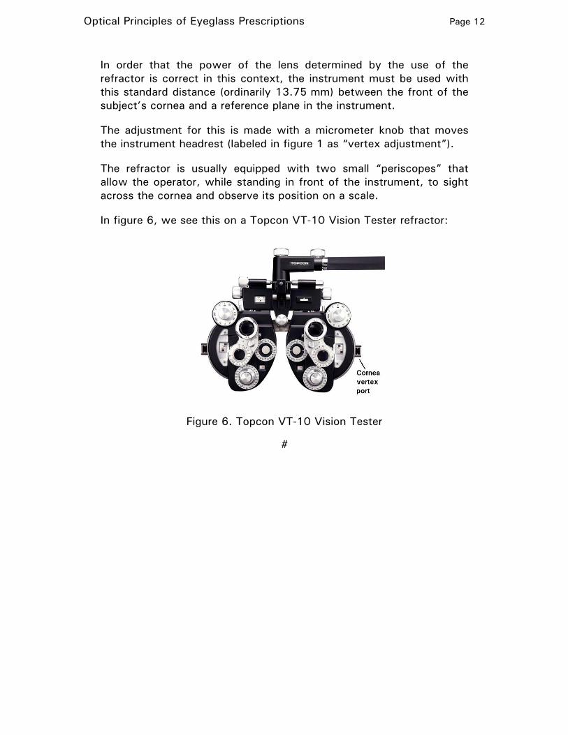
In order that the power of the lens determined by the use of the refractor is correct in this context, the instrument must be used with this standard distance (ordinarily 13.75 mm) between the front of the subject’s cornea and a reference plane in the instrument.
The adjustment for this is made with a micrometer knob that moves the instrument headrest (labeled in figure 1 as “vertex adjustment”).
The refractor is usually equipped with two small “periscopes” that allow the operator, while standing in front of the instrument, to sight across the cornea and observe its position on a scale.
In figure 6, we see this on a Topcon VT-10 Vision Tester refractor:
Figure 6. Topcon VT-10 Vision Tester
#
Optical Principles of Eyeglass Prescriptions Page 13
APPENDIX A
The Jackson cross cylinder
In the use of a manual refractor, the optimal optical parameters are determined empirically. To ascertain an initial value for the sphere power, lenses of different sphere power are put in place with the sphere wheel until the subject reports that the most clear vision is obtained. The setting will typically be refined by “bracketing”: if the subject reports that +1.50 is better than +1.75, and that +1.50 is better than +1.25, then +1.50 is chosen.7 It is here that we first encounter that classical patter, “which is better, one or two”.
A similar approach is used to get an initial choice for the cylinder power and cylinder axis for astigmatism correction. But in this regime, the perceptual impact of less-than-ideal correction is a bit more subtle than in basic spherical correction (where the result is just an “out of focus” appearance). Further, the cylinder axis control on the refractor, being continuous, does not lend itself to simple back-and-forth change between two “bracketing” values.
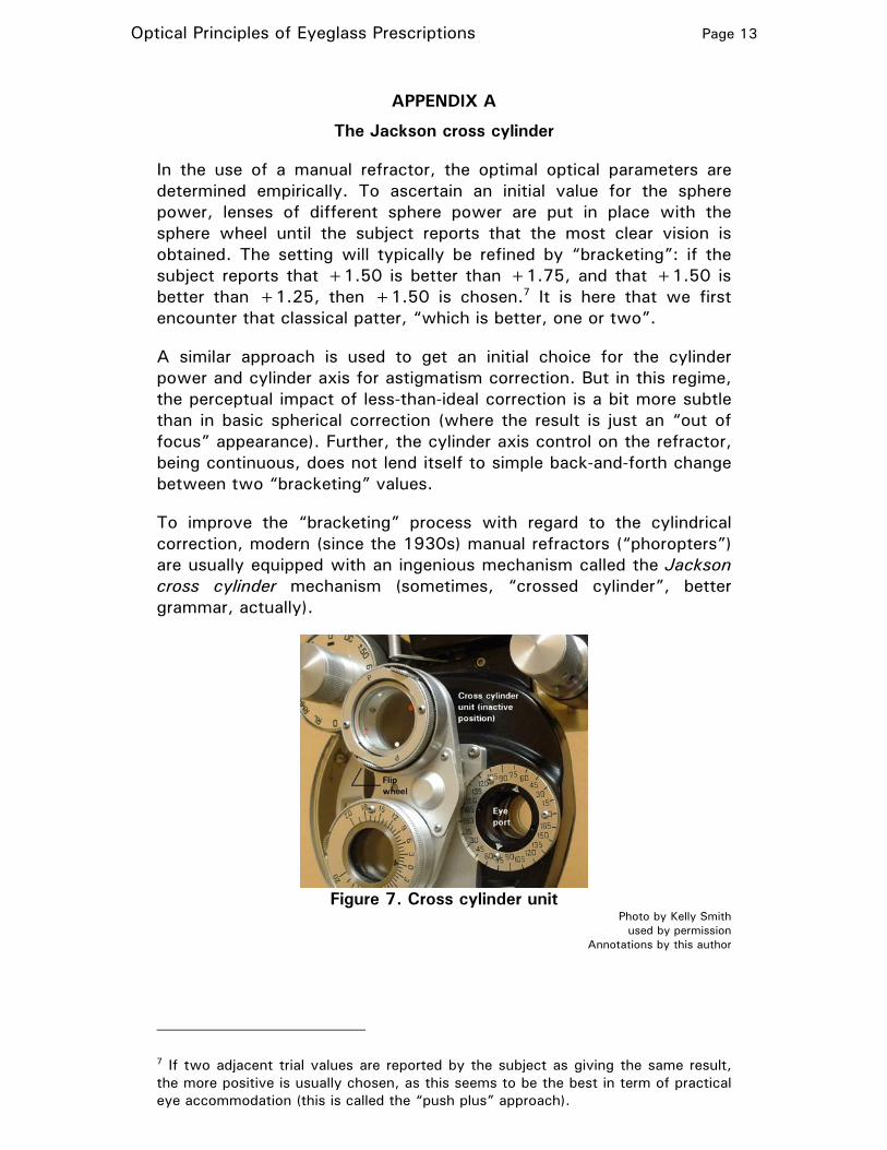
To improve the “bracketing” process with regard to the cylindrical correction, modern (since the 1930s) manual refractors (“phoropters”) are usually equipped with an ingenious mechanism called the Jackson cross cylinder mechanism (sometimes, “crossed cylinder”, better grammar, actually).
Figure 7. Cross cylinder unit
Photo by Kelly Smith used by permission
Annotations by this author
7 If two adjacent trial values are reported by the subject as giving the same result, the more positive is usually chosen, as this seems to be the best in term of practical eye accommodation (this is called the “push plus” approach).
Optical Principles of Eyeglass Prescriptions Page 14
In figure 7, we see it on the right eye portion of a manual refractor (I think it is a Woodlyn). It is mounted on a swing arm, and in its inactive position (shown here) is not in the optical path for the eye.
After the initial cylinder power and axis settings are made, the cross cylinder unit is swung into place in front of the eye port.
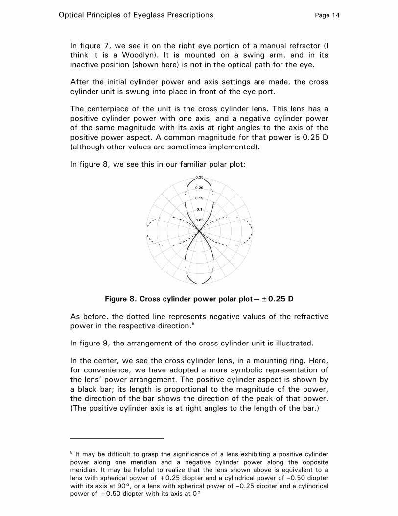
The centerpiece of the unit is the cross cylinder lens. This lens has a positive cylinder power with one axis, and a negative cylinder power of the same magnitude with its axis at right angles to the axis of the positive power aspect. A common magnitude for that power is 0.25 D (although other values are sometimes implemented).
In figure 8, we see this in our familiar polar plot:
0.05
0.1
0.15
0.20
0.25
Figure 8. Cross cylinder power polar plot—±0.25 D
As before, the dotted line represents negative values of the refractive power in the respective direction.8
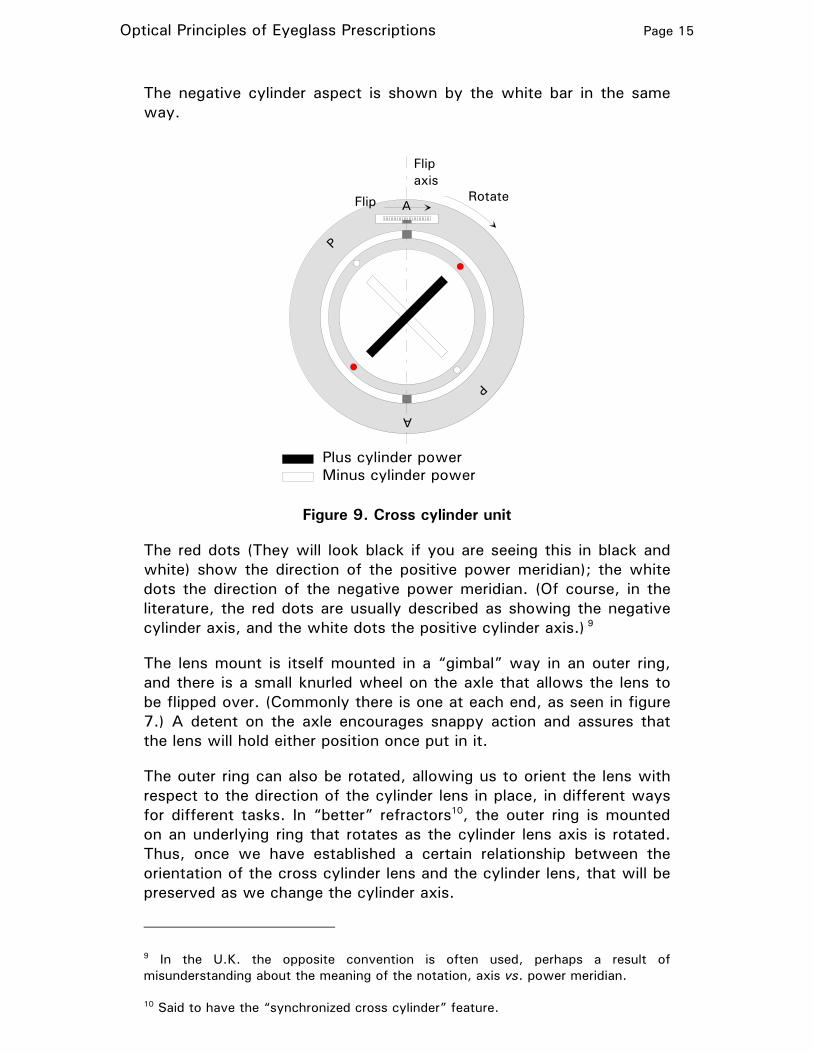
In figure 9, the arrangement of the cross cylinder unit is illustrated.
In the center, we see the cross cylinder lens, in a mounting ring. Here, for convenience, we have adopted a more symbolic representation of the lens’ power arrangement. The positive cylinder aspect is shown by a black bar; its length is proportional to the magnitude of the power, the direction of the bar shows the direction of the peak of that power. (The positive cylinder axis is at right angles to the length of the bar.)
8 It may be difficult to grasp the significance of a lens exhibiting a positive cylinder power along one meridian and a negative cylinder power along the opposite meridian. It may be helpful to realize that the lens shown above is equivalent to a lens with spherical power of +0.25 diopter and a cylindrical power of –0.50 diopter with its axis at 90°, or a lens with spherical power of –0.25 diopter and a cylindrical power of +0.50 diopter with its axis at 0°
Optical Principles of Eyeglass Prescriptions Page 15
The negative cylinder aspect is shown by the white bar in the same way.
Flipaxis
Flip Rotate
P
A
Plus cylinder powerMinus cylinder power
P
A
Figure 9. Cross cylinder unit
The red dots (They will look black if you are seeing this in black and white) show the direction of the positive power meridian); the white dots the direction of the negative power meridian. (Of course, in the literature, the red dots are usually described as showing the negative cylinder axis, and the white dots the positive cylinder axis.) 9
The lens mount is itself mounted in a “gimbal” way in an outer ring, and there is a small knurled wheel on the axle that allows the lens to be flipped over. (Commonly there is one at each end, as seen in figure 7.) A detent on the axle encourages snappy action and assures that the lens will hold either position once put in it.
The outer ring can also be rotated, allowing us to orient the lens with respect to the direction of the cylinder lens in place, in different ways for different tasks. In “better” refractors10, the outer ring is mounted on an underlying ring that rotates as the cylinder lens axis is rotated. Thus, once we have established a certain relationship between the orientation of the cross cylinder lens and the cylinder lens, that will be preserved as we change the cylinder axis.
9 In the U.K. the opposite convention is often used, perhaps a result of misunderstanding about the meaning of the notation, axis vs. power meridian.
10 Said to have the “synchronized cross cylinder” feature.
Optical Principles of Eyeglass Prescriptions Page 16
The notations “A” and “P” (often the “A” is not marked) have to do with two orientations of the cross cylinder lens with the cylinder lens, used for the two different functions of the cross cylinder unit—more about that shortly. A ball detent makes those two orientations mechanically stable.
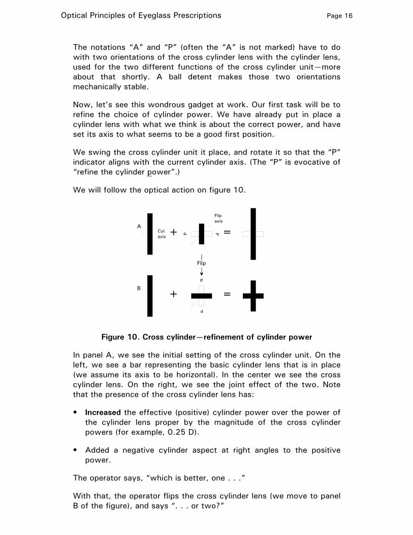
Now, let’s see this wondrous gadget at work. Our first task will be to refine the choice of cylinder power. We have already put in place a cylinder lens with what we think is about the correct power, and have set its axis to what seems to be a good first position.
We swing the cross cylinder unit it place, and rotate it so that the “P” indicator aligns with the current cylinder axis. (The “P” is evocative of “refine the cylinder power”.)
We will follow the optical action on figure 10.
+ =
+ =
Flip
A
BP
P P
P
Cyl.axis
Flipaxis
Figure 10. Cross cylinder—refinement of cylinder power
In panel A, we see the initial setting of the cross cylinder unit. On the left, we see a bar representing the basic cylinder lens that is in place (we assume its axis to be horizontal). In the center we see the cross cylinder lens. On the right, we see the joint effect of the two. Note that the presence of the cross cylinder lens has:
• Increased the effective (positive) cylinder power over the power of the cylinder lens proper by the magnitude of the cross cylinder powers (for example, 0.25 D).
• Added a negative cylinder aspect at right angles to the positive power.
The operator says, “which is better, one . . .”
With that, the operator flips the cross cylinder lens (we move to panel B of the figure), and says “. . . or two?”
Optical Principles of Eyeglass Prescriptions Page 17
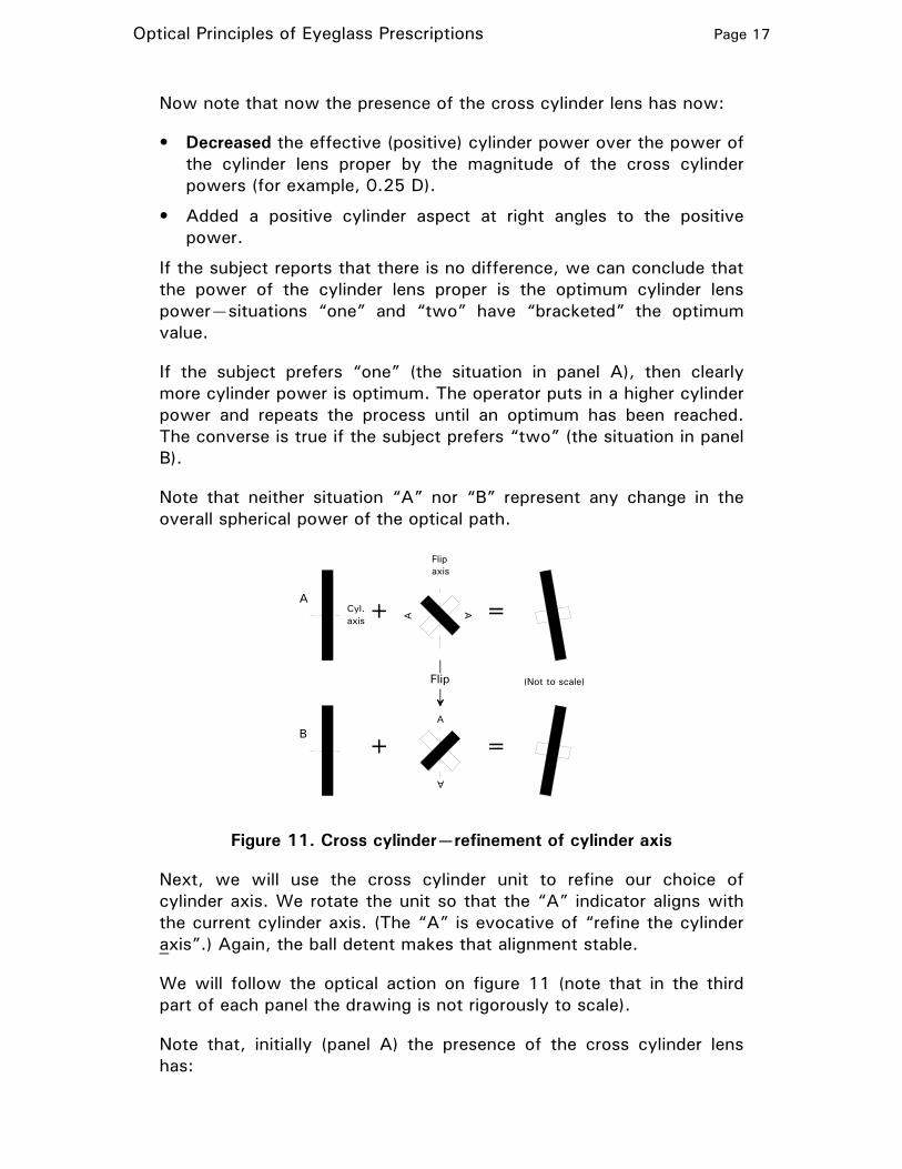
Now note that now the presence of the cross cylinder lens has now:
• Decreased the effective (positive) cylinder power over the power of the cylinder lens proper by the magnitude of the cross cylinder powers (for example, 0.25 D).
• Added a positive cylinder aspect at right angles to the positive power.
If the subject reports that there is no difference, we can conclude that the power of the cylinder lens proper is the optimum cylinder lens power—situations “one” and “two” have “bracketed” the optimum value.
If the subject prefers “one” (the situation in panel A), then clearly more cylinder power is optimum. The operator puts in a higher cylinder power and repeats the process until an optimum has been reached. The converse is true if the subject prefers “two” (the situation in panel B).
Note that neither situation “A” nor “B” represent any change in the overall spherical power of the optical path.
+ =
+ =
Flip
A
BA
A
A
A
Cyl.axis
Flipaxis
(Not to scale)
Figure 11. Cross cylinder—refinement of cylinder axis
Next, we will use the cross cylinder unit to refine our choice of cylinder axis. We rotate the unit so that the “A” indicator aligns with the current cylinder axis. (The “A” is evocative of “refine the cylinder axis”.) Again, the ball detent makes that alignment stable.
We will follow the optical action on figure 11 (note that in the third part of each panel the drawing is not rigorously to scale).
Note that, initially (panel A) the presence of the cross cylinder lens has:
Optical Principles of Eyeglass Prescriptions Page 18
• Rotated the axis (and the power direction) of the cylinder correction slightly counterclockwise.
• Added a negative cylinder aspect at right angles to the positive power (essentially inconsequential).
The operator says, “which is better, one . . .”
With that, the operator flips the cross cylinder lens (we move to panel B of the figure), and says “. . . or two?”
Now the presence of the cross cylinder lens has:
• Rotated the axis (and the power direction) of the cylinder correction slightly clockwise.
• Added a negative cylinder aspect at right angles to the positive power (essentially inconsequential).
If the subject reports that there is no difference, we can conclude that the axis of the cylinder lens proper is the optimum cylinder lens axis—situations “one” and “two” have “bracketed” the optimum value.
If the subject prefers “one” (the situation in panel A), then clearly a cylinder axis greater than that now in place (that is, farther counterclockwise) is optimum. The operator increases the cylinder axis and repeats the process until an optimum has been reached.
The converse is true if the subject prefers “two” (the situation in panel B).
Note that again neither situation “A” nor “B” represent any change in the overall spherical power of the optical path.
Historical background
Sir George Gabriel Stokes developed a variable-power cylindrical lens, which he described in an 1849 paper, suggesting its use to determine the optimal cylindrical power to correct astigmatism. It comprises two cylindrical lenses, one with a positive power, and the other with a negative cylindrical power of the same magnitude.
The two lenses are mounted together so that the relative orientations of their axes could be varied. When the two axes are aligned, the net power (cylindrical and spherical) is zero. When the two axes are at right angles, the situation is that illustrated in figure 8: along one meridian there is a positive cylinder power of a certain magnitude (the magnitude of the power of either component lens), and along the other meridian, at right angles, there is a negative cylinder power of the same magnitude.
Optical Principles of Eyeglass Prescriptions Page 19
With some other angle between the two components, the composite lens presents an intermediate positive cylindrical power on one meridian, and the same negative cylinder power on the opposite meridian.
Note that in this situation, the overall result can be considered equivalent to a lens with both either:
• A positive spherical component and a negative cylindrical component, or
• A negative spherical component and a positive cylindrical component
The use of a Stokes lens to determine the optimum cylindrical power in eyeglasses was done in a context where the optimal spherical power was found by placing spherical lenses with varying power, from a set, into an eyeglass-like holder worn by the subject. A Stokes lens was then added to the mix, with its “setting” (angle between the axes of its components) adjusted to vary the cylinder effect, and its overall angle adjusted to vary the cylinder axis. And of course, a spherical component was also added, which had to be taken into account in recording the overall indicated prescription.
Edward Jackson, in 1897, published a paper in which a Stokes lens, fixed at the “cylinder axes at right angles” state, could be used (by “flipping”) to increment and then decrement the power of a “trial” cylindrical lens, allowing for convenient “bracketing” to ascertain the optimal cylindrical power (just as we saw above in figure 10). Thus a Stokes lens, with the axes of the two elements fixed at right angles, became the “Jackson cross cylinder” lens.
Twenty years later, in 1907, Jackson published another paper in which he showed that this same “cross cylinder” setup could be also used to make incremental changes in the effective axis of a cylindrical lens, allowing for convenient “bracketing” to ascertain the optimal cylindrical axis (just as we saw above in figure 11).
The use of the Jackson cross cylinder arrangement on manual refractors seemingly emerged some time in the 1930s.
#
Optical Principles of Eyeglass Prescriptions Page 20
APPENDIX B
Variation of refractive behavior
The following observations, relevant to the material in this article, are offered without proof.
Effect of a cylindrical component on overall spherical power
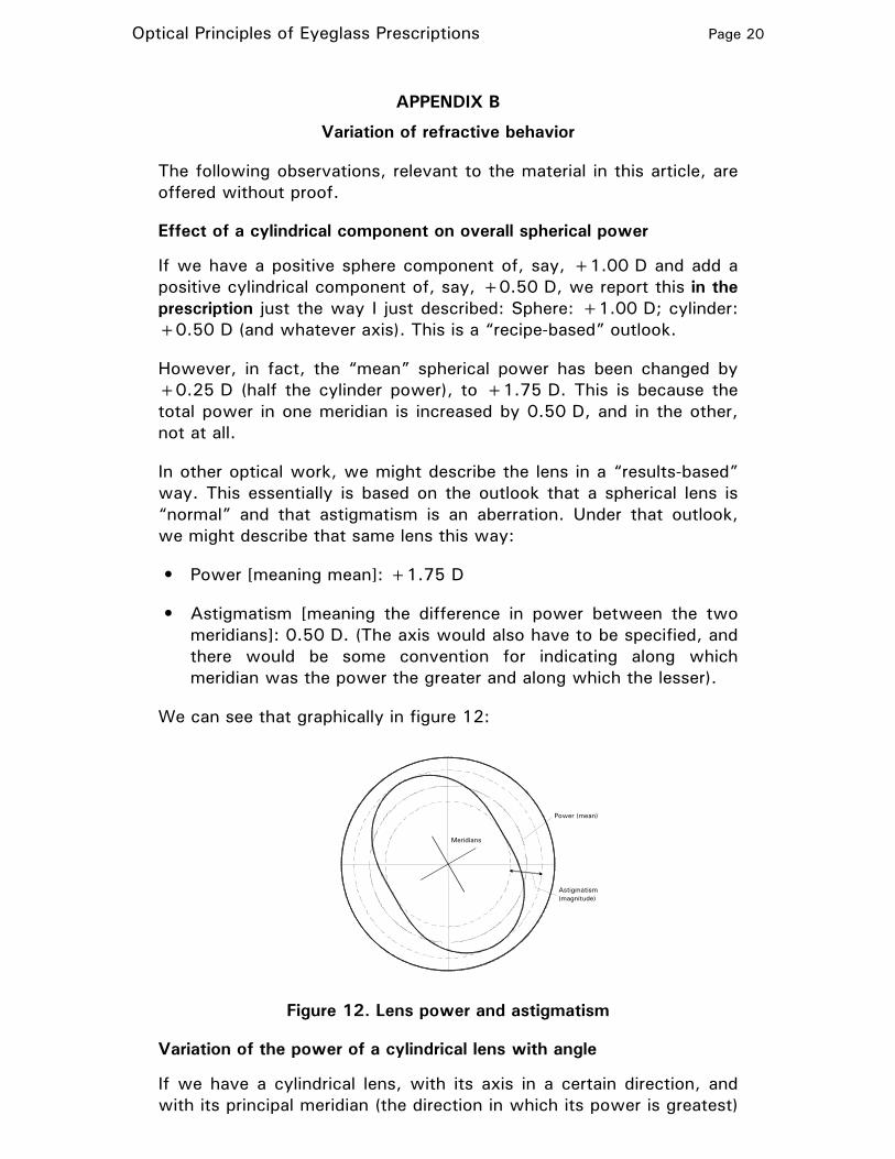
If we have a positive sphere component of, say, +1.00 D and add a positive cylindrical component of, say, +0.50 D, we report this in the prescription just the way I just described: Sphere: +1.00 D; cylinder: +0.50 D (and whatever axis). This is a “recipe-based” outlook.
However, in fact, the “mean” spherical power has been changed by +0.25 D (half the cylinder power), to +1.75 D. This is because the total power in one meridian is increased by 0.50 D, and in the other, not at all.
In other optical work, we might describe the lens in a “results-based” way. This essentially is based on the outlook that a spherical lens is “normal” and that astigmatism is an aberration. Under that outlook, we might describe that same lens this way:
• Power [meaning mean]: +1.75 D
• Astigmatism [meaning the difference in power between the two meridians]: 0.50 D. (The axis would also have to be specified, and there would be some convention for indicating along which meridian was the power the greater and along which the lesser).
We can see that graphically in figure 12:
Power (mean)
Astigmatism(magnitude)
Meridians
Figure 12. Lens power and astigmatism
Variation of the power of a cylindrical lens with angle
If we have a cylindrical lens, with its axis in a certain direction, and with its principal meridian (the direction in which its power is greatest)
Optical Principles of Eyeglass Prescriptions Page 21
at right angles to that, then the power exhibited in any other direction is the product of its greatest power (said to be “the power” of the lens) times the square of the cosine of the angle between the direction of interest and the principal meridian.
This situation may at first seem equivalent to the matter of resolving a vector (a force, for example), in a two-dimensional context, into two components, one lying along some direction of interest and the other in right angles to that.
In that situation, the component in the direction of interest is equal to the magnitude of the vector times the cosine of the angle between the direction of interest and the direction of the vector itself. We might have expected to find that in the present situation.
But the two situations are not at all equivalent.
In the case of resolving a vector, the two components replace the vector. If we consider them, then the vector itself is not in play anymore, and there can be no other components of the vector in play—only those two.
In the case of the variation of power of the cylinder lens, the lens exhibits power in every direction (except along the cylinder axis) all the time. Its power in some oblique direction is not a replacement for its power along its primary meridian—they both coexist, along with the powers in all other directions.
So it should not be a surprise that different variations with angle are involved in the two cases.
#