the rem telescope: a robotic facility to monitor the...
TRANSCRIPT
Mem. S.A.It. Vol. 74, 304c© SAIt 2003 Memorie della
The REM telescope: a robotic facility to monitorthe prompt afterglow of gamma ray bursts
L. A. Antonelli1,?, F. M. Zerbi2, G. Chincarini2,3, G. Ghisellini2, M. Rodono4,G. Tosti5, P. Conconi2, S. Covino2, G. Cutispoto4, E. Molinari2, L. Nicastro6,
F. Vitali1, and E. Palazzi7
1 INAF, Osservatorio Astronomico di Roma, Monte Porzio Catone, Italy2 INAF, Osservatorio Astronomico di Brera, Merate, Italy3 Dipartimento di Fisica, Universita di Milano Bicocca, Milano, Italy4 INAF, Osservatorio Astrofisico di Catania, Catania, Italy5 Dipartimento di Fisica, Universita di Perugia, Perugia, Italy6 CNR, Istituto di Astrofisica Spaziale, Sezione di Palermo, Palermo, Italy7 CNR, Istituto di Astrofisica Spaziale, Sezione di Bologna, Bologna, Italy
Abstract. Observations of the prompt afterglow of Gamma Ray Burst events areof paramount importance for GRB science and cosmology. In particular earlyobservations at NIR wavelengths are even more promising allowing one to discoverand monitor high-z Ly-α absorbed bursts as well as events occurring in dustystar-forming regions. In these pages we present REM (Rapid Eye Mount), a fullyrobotized fast slewing telescope equipped with a high throughput NIR (Z′, J , H,K′) camera (REMIR) and an Optical Slitless Spectrograph (ROSS), dedicatedto detect and study prompt IR and optical afterglow. The REM telescope willsimultaneously feed REMIR and ROSS via a dichroic. The synergy between theREMIR camera and the ROSS spectrograph makes REM a powerful observing toolfor any kind of fast transient phenomena providing an unprecedented simultaneouswavelength coverage on a telescope of this size. Beside its ambitious scientific goals,REM is also technically challenging since it represent the first attempt to locatea NIR camera on such a small telescope.
Key words. instrumentation: miscellaneous – telescopes – gamma rays: bursts
Send offprint requests to: L. A. Antonelli? On behalf of the REM/ROSS team
Correspondence to: INAF, Osservatorio Astro-nomico di Roma, Via Frascati 33, I-00040Monte Porzio Catone, Italy
1. Introduction
REM (Rapid Eye Mount) is a fully roboticfast-slewing telescope primarily designed tofollow the early phases of the afterglow ofGamma Ray Bursts (GRB) detected bySpace-borne-alert systems such as HETEII, INTEGRAL, AGILE, Swift. REM is

L. A. Antonelli et al.: Rapid Eye Mount telescope 305
currently in its final integration phase andwill be installed in the La Silla Observatory(Chile) at the beginning of 2003. REMhosts a NIR (Near Infra-Red) camera cov-ering the 0.95-2.3 µm range with 4 filters(Z ′, J , H, K ′) and ROSS (REM OpticalSlitless Spectrograph), a slitless spectro-graph covering the range 0.45-0.95 µm with30 sample points. With these instrumentsREM will serve as a Rapid-pointing broadband spectro-photometric facility wheneverprompt multi-wavelength data are needed.
REM is an ambitious project since itcan lead to the discovery and study of themost distant astronomical sources ever ob-served so far. It is known that roughly a halfof the observed GRBs do not show any op-tical afterglow. At least a part of them canbe high-z bursts for which Ly-α absorp-tion dumps all the light at optical wave-lengths. Ly-α absorption falls in the REMwavelength range for sources with red-shiftbetween 8 and 15, i.e. any burst in thisrange can still be detected by REM and itsposition determined with an accuracy of afew tenth of arcsec. The astrometry will bemade available on a time-scale of tenths ofsecond allowing one to observe the tran-sient with larger area telescopes when itis still very bright. A 8-m class telescopeequipped with suitable IR spectrographscould collect a high resolution high S/Nspectrum of a source at z > 10, i.e. themost distance source within or beyond therange of the expected red-shift of reioniza-tion (8 < z < 20).
The optical slitless spectrograph,ROSS, is as well an outstanding instru-ment since it will intensively monitor theshape of the optical afterglow continuumand its early temporal behaviour. ROSSwill allow to constrain the models forthe prompt afterglow emission and willprovide, together with REMIR camera,useful information about GRB progenitorsand GRB environments.
Fig. 1. The optical flash of GRB 990123as seen by ROTSE. Part of the opticalUV photons could have been absorbed bydust, in the first part of the emission. Afterdust has evaporated, the line of sight be-come extinction free. Since IR photons aremuch less absorbed by dust, they couldpass nearly unabsorbed, resulting in a moreprompt emission.
2. REM and gamma ray bursts
Gamma Ray Bursts are bright, transientevents in the γ-ray sky, unpredictable intime and location, with a typical durationof the order of seconds. The burst eventis immediately followed by a fading emis-sion observable at all wavelengths calledafterglow. But if 95% of GRBs show aX-ray afterglow almost 50% of them donot show any optical/NIR afterglow at all.In the case in which an optical afterglowhas been detected the typically monochro-matic flux of its decreases in time as apower law Fν(t) ∼ t−δ with δ in the range0.8-2. Typical magnitudes of optical after-glow detected about one day after the γ-ray event are in the range 19-21. Assumingm = 19 after 24 hours and δ ∼ 1.5, the ex-pected magnitude after 1 hour is ∼ 13.8.Although we have only two examples ofprompt optical/IR emission during the firstminutes of the afterglow (GRB 990123 andGRB 020813) they substantially confirmedour estimations of typical early magnitudesof GRBs afterglow. GRB 990123 (Fig. 1)has been detected by the robotic telescopeROTSE about 22 seconds after the γ-raytrigger at m ∼ 11.7 and reaching m ∼

306 L. A. Antonelli et al.: Rapid Eye Mount telescope
8.9 47 seconds after the trigger (Akerlof& McKay 1999). GRB 021004 has beendetected by the robotic telescope 48-inchOschin/NEAT 567 seconds after the γ-raytrigger at R = 15.34 mag (Fox 2002).
REM telescope with its NIR camera isexpected to reach magnitude H = 15.5,16.04 and 17.11 with exposure times of 5,30 and 600 seconds respectively (S/N = 5).With the ROSS spectrograph a V = 14point-like source is recorded better than10σ in 1 sec exposures. These numbers sug-gest that we could detect and study an IRafterglow during the first 2-4 hours evenwith an exposure time of 5 seconds. Thiswill allow the study of the light curve andeventual flickering in great detail, the de-tection of possible (even if short) variationsfrom the smooth power-law behavior andthe definition of any possible break (Fig.2). Increasing the exposure time (after theinitial phases) to 10 minutes, we can followtypical bursts up to 12 hours, after whichlarger telescopes can take over. There aremany key points we expect that REM canaddress concerning cosmology and GRBsscience.
Fig. 2. The optical light curve of GRB980519, with 3 possible extrapolation to-wards earlier times. Should the early after-glow behave normally (i.e. with a t−1) wewould have evidence of beaming.
High-z bursts. The simultaneous detec-tion in the IR and a non-detection inthe optical can directly flag the presenceof a high-z object. In fact if a burst is
at high-z, Ly-α absorption dumps all thelight at optical wavelengths. Ly-α absorp-tion falls in the REMIR camera wavelengthrange for sources with redshift between 8and 15 and through color-color techniqueswe can select good candidates high-z ob-jects automatically and in real time. Largertelescopes can then point at the targetwhile it is still bright enough for high-dispersion spectroscopic observations in or-der to study matter distribution and metal-licity in the early Universe.
Reddened bursts. At low redshifts thelack of optical afterglow can be due to ab-sorption by intervening matter (dust), ei-ther in the close vicinity of the burst (ifexploded in a dense star forming regionwhose dust has not been completely de-stroyed by the burst emission itself), orby dust distributed along the line of sight,even at large distances from the burst site.In this case the infrared light is much lessabsorbed, and therefore an IR transientcan be detected even if the optical is not.From this point of view, the REM tele-scope, combining the two (IR and optical)datasets, will makes possible to estimatethe amount of absorption and consequentlyof the circum-burst medium (e.g. Fig. 3).
Fig. 3. The infrared (H band) light curveof GRB 990705 (Masetti et al. 2000), with apossible extrapolation towards earlier timesand the only detected point in the V band.The estimated V − H color is 3.5-4, sug-gesting either a steep continuum or strongreddening.
L. A. Antonelli et al.: Rapid Eye Mount telescope 307
Broad band spectrum. Even if the the-ory of afterglow emission (due to syn-chrotron) is largely accepted, the best con-straints we have come from observationsperformed one or several days after theGRB. It is however possible (if not evenlikely) that at the beginning of the after-glow the physical conditions (density andtemperature) of the shocked material aremore extreme and that different emissionprocesses (e.g. Comptonization) are domi-nant. Increasing the ‘frequency leverage’ istherefore of great importance to better de-termine the spectrum of the early afterglowin order to better understand the afterglowemission processes.
3. REM and ancillary science
As all other robotic facilities dedicated toGRB science, REM reacts to a trigger froma space-borne satellite. This means that fora considerable amount of time REM willbe idle in the sense that it will not bepointing any GRB transient. Such a timedepends on the number of public triggerseventually provided by missions scheduledto fly during REM operation and it canbe estimated around 40% of total REMobserving time. During such idle phaseREM will serve the community as a fastpointing NIR imager particularly suitablefor multi-frequency monitoring of highlyvariable and transient sources. Some Key-programs of interest for the REM-teamhave been identified. In particular REMwill be used to monitor Flaring Stars, tomonitor Blazar and AGN, and, in associa-tion with INTEGRAL, to monitor GalacticBlack Hole Candidates.
4. The hardware
The REM telescope and its instrumenta-tion are currently in the final stage of in-tegration at Brera Observatory (Merate,Italy). The major part of hardware has beendelivered and is currently be assembled andtested into each subsystem. In this section
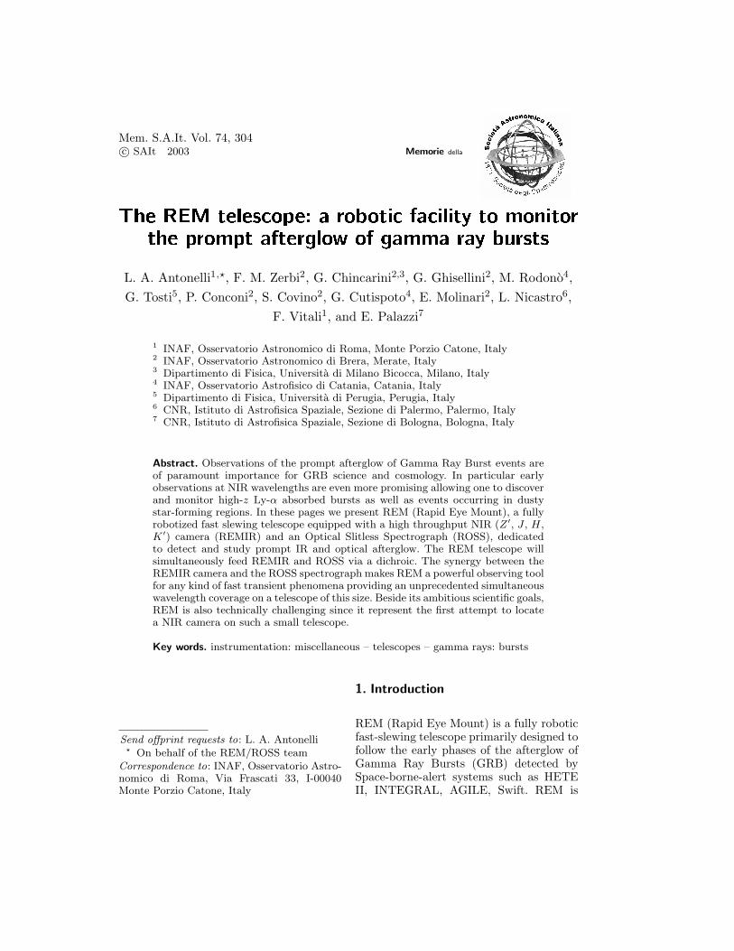
Fig. 4. The REM telescope.
we give a description of the main charac-teristics of each subsystem.
4.1. The REM telescope
The REM telescope (Fig. 4) is a Ritchey-Chretien system with a 60 cm f/2.2 primaryand a overall f/8 focal ratio mounted in analt-azimuth mount in order to provide sta-ble Nasmyth focal stations, suitable for fastmotions. REM has two Nasmyth focal sta-tions although at first light one will remainidle. At the first focal station a dichroic,working at 45 degrees in the f/8 conver-gent beam, will split the beam to feed thetwo first light instruments of the REM tele-scope: the REMIR camera and the ROSSSpectrograph.The telescope has been manufacturedby Teleskoptechnik Halfmann Gmbh in

308 L. A. Antonelli et al.: Rapid Eye Mount telescope
Fig. 5. Hexagonal support for instruments.
Augsburg (Germany). Mirrors are madeby Carl Zeiss AG (Germany) and theyare coated with protected silver to max-imize reflection efficiency in such a large(0.45 - 2.3 µm) wavelength range. The al-titude and azimuth motors made by ETELallows a maximum speed of 12 degreesec−1 on both axis while the Heidenain en-coders (237 steps per arcsec) allows excel-lent pointing, slewing and tracking preci-sions.The mechanical structure has been de-signed with stiffness in mind, because ofthe fast motion, but also taking into ac-count the background contamination atNIR wavelength.The image at the Nasmyth focal stationin use is de-rotated and the instrumen-tal flange is designed to receive a load of250 Kg to be compared to the actual esti-mated total weight of the instrumentationof about 70 Kg.
The de-rotated Nasmyth focal stationwill host both the first light instrumentsREMIR and ROSS. These instrument willbe mounted onto an hexagonal instrumentflange (Fig. 5), REMIR along the Nasmythoptical axis and ROSS orthogonal to such
axis. The choice of the hexagonal shapeallows also to load the control cabinetsof the instruments that have to be de-rotated with them. Inside the hexagonalflange the light repartition is done by adichroic working at 45o in f/8 convergentbeam. Since no commercial products of thiskind are available the dichroic has been de-signed at gOlem laboratories of the BreraObservatory (Merate, Italy) and manufac-tured in collaboration with ZAOT coat-ing laboratories (Milano, Italy). The de-sign phase was aimed to achieve the max-imum possible transmission at IR wave-lengths (0.95-2.3 µm) and the maximumpossible reflection at Optical wavelength(0.45-0.95 µm) in the effective working con-ditions and taking into account of the re-sponse of both optical and IR detectors.The adopted solution provides a cut at 0.95µm and is made of a multi-layer coating ofMgF2 and ZnSe on a substrate of IR-SiO2
. The obtained reflectivity is the averagebetween that at 42◦ and 48◦. The trans-mission of the device is strictly complemen-tary to the reflectivity since the materialsused have negligible absorption. The aver-age reflectivity between 0.45 and 0.90 µmis 0.965 with a minimum of 0.880. The av-erage transmission between 1 and 2.3 µmis 0.972 with a minimum of 0.91.
4.2. The REM IR camera (REMIR)
The REMIR camera (see Vitali et al. 2002for more details) follows a focal reducer de-sign in order to reform a white pupil in acold environment for Lyot-stop positioning(see Fig. 6). A filter wheel with 10 positionsis located at the reformed pupil allowingone to insert filters and grisms for slit-lessspectroscopy or polarimeters in a parallelbeam. The camera changes the focal ratiofrom f/8 to f/5.3 providing a plate-scale of64.4 arcsec mm−1 that allows one to posi-tion a 9.9×9.9 arcmin2 FOV on a 512×512(18 µm pitch) HgCdTe chip produced byRockwell.The REMIR lenses have been designed atgOlem laboratories, (Merate, Italy) and

L. A. Antonelli et al.: Rapid Eye Mount telescope 309
Fig. 6. REMIR optical train.
manufactured by Gestione SILO (Florence,Italy). Both collimator and camera (Fig. 6)are made of a Silica-CaF2 doublet (the lat-ter reverse-mounted) with the peculiarityof being more thick than large. Other opti-cal elements are the Cryostat window lensand a field corrector lens near the FPA. Thetotal thickness of the optical design is 345mm. The image quality is optimal as canbe seen in the spot diagrams reported inFig. 7.The Filter for the REM-IR camera arestandard high performance IR filters. TheJ , H and Ks units have been orderedto Barr Associates Inc. in the frameworkof the international Consortium lead byUniversity of Hawaii (PI A. Tokunaga).These filters are high performance filters forastronomy manufactured with a special set-up. Beside these standards NIR band welocated in REMIR a 1micron filter alreadyused in instruments such as NICS at theGalileo National Telescope, manufacturedby Omega Filters. The purpose of this filteris to take profit of the light at wavelengthshorter than the J band that atmosphereand dichroic let pass and that the HgCdTechip is still in condition to detect.
The whole camera train is mounted ina dewar, designed and manufactured byIRLabs (Tucson, AZ), and operated in acool environment. The chip working tem-perature is 77 K and will be guaranteed atthe detector location and at the cold stopposition. The optical train is kept at a tem-perature of about 100-120 K in order tosave cooling power. The cryogenics are sup-ported by a Stirling-Cycle cryo-pump madeby Leybold AG (Germany) requiring lim-ited maintenance and no need for dewar re-filling. A sketch of the mechanical layout ofREMIR camera is shown in Fig. 8.
Fig. 7. REMIR spot diagrams.
Fig. 8. Schematics of the REM-IR cryo-mechanical system (courtesy of IRLabs).
The chip is a Rockwell HAWAII 1024×1024 with 3 out of four quadrant working.Such an unpredictable circumstance (we or-dered a chip with a single quadrant work-ing) will allow us to change the workingquadrant once the performances degrada-tion of the one in use will no longer be ac-ceptable. The chip is controlled by a LeachController and read-out at 1.5 microsecond
310 L. A. Antonelli et al.: Rapid Eye Mount telescope
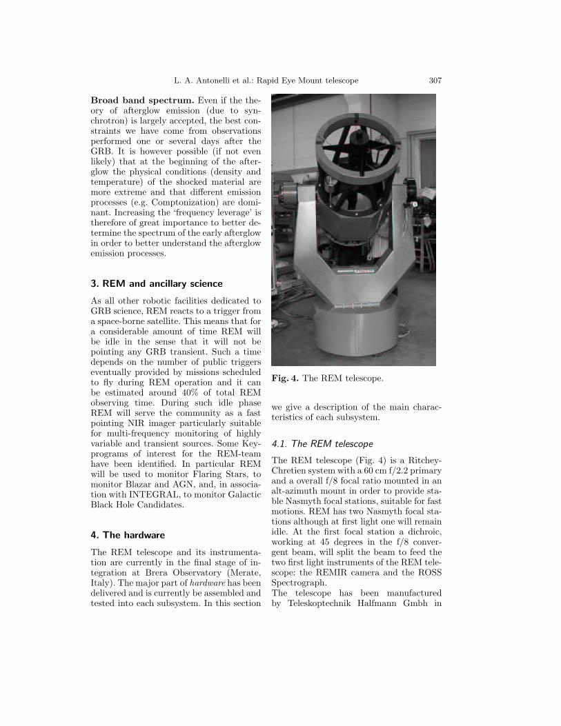
Fig. 9. ROSS optical layout.
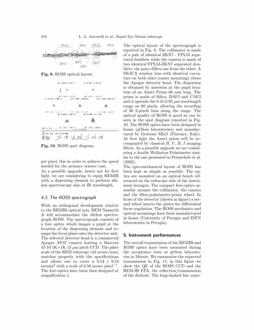
Fig. 10. ROSS spot diagram.
per pixel, this in order to achieve the speedneeded for the primary science case.As a possible upgrade, hence not for firstlight, we are considering to equip REMIRwith a dispersing element to perform slit-less spectroscopy also at IR wavelength.
4.3. The ROSS spectrograph
With an orthogonal development relativeto the REMIR optical axis, REM NasmythA will accommodate the slitless spectro-graph ROSS. The spectrograph consists ofa fore optics which images a pupil at thelocation of the dispersing element and re-maps the focal plane onto the detector unit.The selected detector head is a commercialApogee AP47 camera hosting a Marconi47-10 1K×1K 13 µm pitch CCD. The platescale of the REM telescope (43 arcsec/mm)matches properly with the specificationsand allows one to cover a 9.54 × 9.54arcmin2 with a scale of 0.56 arcsec pixel−1.The fore-optics have been then designed atmagnification 1.
The optical layout of the spectrograph isreported in Fig. 9. The collimator is madeof a pair of identical ZKN7 - FPL53 sepa-rated doublets while the camera is made oftwo identical FPL53-ZKN7 separated dou-blets: the pairs differs one from the other. ASILICA window lens with identical curva-ture on both sides (easier mounting) closesthe Apogee detector head. The dispersionis obtained by insertion at the pupil loca-tion of an Amici Prism 66 mm long. Theprism is made of Silica, BAF2 and CAF2and it spreads the 0.45-0.95 µm wavelengthrange on 60 pixels, allowing the recordingof 30 2-pixels bins along the range. Theoptical quality of ROSS is good as can beseen in the spot diagram reported in Fig.10. The ROSS optics have been designed inhouse (gOlem laboratories) and manufac-tured by Gestione SILO (Florence, Italy).At first light the Amici prism will be ac-companied by classical B, V , R, I imagingfilters. As a possible upgrade we are consid-ering a double Wollaston Polarimeter simi-lar to the one presented in Pernechele et al.(2002).The opto-mechanical layout of ROSS hasbeen kept as simple as possible. The op-tics are mounted on an optical bench ref-erenced on the telescope side of the instru-ment hexagon. The compact fore-optics as-sembly mounts the collimator, the cameraand the filter-polarimeter-prism wheel. Infront of the detector (shown in figure) a sec-ond wheel inserts the plates for differentialfocus regulation. The ROSS mechanics andoptical mountings have been manufacturedin house (University of Perugia and INFNlaboratories in Perugia).
5. Instrument performances
The overall transmission of the REMIR andROSS optics have been measured duringthe acceptance tests at gOlem laborato-ries in Merate. We summarize the expectedtransmission in Fig. 11; in this figure weshow the QE of the ROSS CCD and theREM-IR FPA, the reflection/transmissionof the dichroic. The long-dashed line repre-
L. A. Antonelli et al.: Rapid Eye Mount telescope 311
0.5 1 1.5 2 2.50
0.2
0.4
0.6
0.8
1
Wavelength [microns]
Dichroic TransmissionMarconi CCD QEHAWAII QEOverall REM/ROSS Eff.
1mic-J H KsAMICI
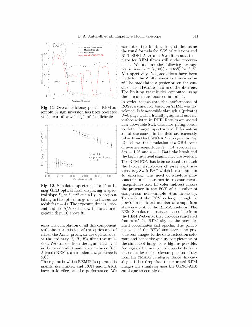
Fig. 11. Overall efficiency pof the REM as-sembly. A sign inversion has been operatedat the cut-off wavelength of the dichroic.
Fig. 12. Simulated spectrum of a V = 14mag GRB optical flash displaying a spec-tral slope Fλ ∝ λ−1.25 and a Ly−α dropoutfalling in the optical range due to the sourceredshift (z = 4). The exposure time is 1 sec-ond and the S/N ∼ 4 below the break andgreater than 10 above it.
sents the convolution of all this componentwith the transmission of the optics and ofeither the Amici prism, on the optical side,or the ordinary J , H, Ks filter transmis-sion. We can see from the figure that evenin the most unfortunate circumstance (theJ band) REM transmission always exceeds30%.The regime in which REMIR is operated ismainly sky limited and RON and DARKhave little effect on the performance. We
computed the limiting magnitudes usingthe usual formula for S/N calculations andNTT-SOFI J , H and Ks filters as a tem-plate for REM filters still under procure-ment. We assume the following averagetransmissions: 75%, 80% and 85% for J , H,K respectively. No predictions have beenmade for the Z filter since its transmissionwill be modulated a posteriori on the cut-on of the HgCdTe chip and the dichroic.The limiting magnitudes computed usingthese figures are reported in Tab. 1.In order to evaluate the performance ofROSS, a simulator based on SLIM1 was de-veloped. It is accessible through a (private)Web page with a friendly graphical user in-terface written in PHP. Results are storedin a browsable SQL database giving accessto data, images, spectra, etc. Informationabout the source in the field are currentlytaken from the USNO-A2 catalogue. In Fig.12 is shown the simulation of a GRB eventof average magnitude R = 14, spectral in-dex = 1.25 and z = 4. Both the break andthe high statistical significance are evident.The REM FOV has been selected to matchthe typical error-boxes of γ-ray alert sys-tems, e.g. Swift-BAT which has a 4 arcmin3σ errorbox. The need of absolute pho-tometric and astrometric measurements(magnitudes and IR color indices) makesthe presence in the FOV of a number ofcomparison non-variable stars necessary.To check if the FOV is large enough toprovide a sufficient number of comparisonstars is a task of the REM-Simulator. TheREM-Simulator is package, accessible fromthe REM Web-site, that provides simulatedframes of the REM sky at the user de-fined coordinates and epochs. The princi-pal goal of the REM-simulator is to pro-vide test images to the data reduction soft-ware and hence the quality completeness ofthe simulated image is as high as possible.As regards the number of objects the sim-ulator retrieves the relevant portion of skyfrom the 2MASS catalogue. Since this cat-alogue is less deep than the expected REMimages the simulator uses the USNO-A1.0catalogue to complete it.

312 L. A. Antonelli et al.: Rapid Eye Mount telescope
T J H K(sec) 10σ 5σ 10σ 5σ 10σ 5σ5 15.5 16.3 14.3 15.1 13.1 13.930 16.4 17.2 15.2 16.0 14.1 14.8600 17.3 18.0 16.3 17.1 15.4 16.1
Table 1. Limiting magnitudes as a func-tion of the S/N (10 or 5) and of the pass-band, for the different integration timesforeseen in the REM target operation.
5.1. REM dome and site
A telescope like REM, specially becauseof the IR camera, has to be located ina dry and high altitude site with goodweather conditions and a high percent-age of observing nights. A viable and re-liable connection to a large facility ac-cepting Target of Opportunity alerts is inaddition an important issue for the suc-cess of the project. For this reason we ex-plored possible agreements with existingObservatories with a natural preference forthe European Southern Observatory site atla Silla and Cerro Paranal, Chile. An agree-ment to install REM at la Silla Observatoryhas been achieved in the framework of theFROST (Fast Robotic Observatory Systemfor Transient), formed by REM and theFrench Project TAROT-S. REM will beinstalled at la Silla Observatory at UTM(Zone 19) E 331,235 N 6,762,735, elevation2,338.80 mt (see the exact location in themap in Fig. 13). The observatory buildingis already built (Fig. 14) and the telescopefirst light is expected for Spring 2003.
6. REM software and operation
6.1. Telescope control software
The robotic character of the REM telescopeand the minimization of the need for hu-man intervention is mainly obtained viaa robust operation scheme and a highlymodular and reliable operation software.The main aim of the project is to de-liver a system able to take decisions ina few seconds without any human inter-
Fig. 13. The site where the REM observa-tory has been built, in between ESO 1.52-m and ESO 1.0-m telescopes at la SillaObservatory, Chile.
Fig. 14. The REM dome.
vention. However, an adequate interfaceto allow a remote human control of op-erations in case of necessity is developed.In principle, our system can be subdi-vided from a logical point of view in sev-eral subsystems managing various dutiesof the experiment: the REM ObservingSoftware (REMOS), the REM TelescopeControl System (REMTCS), the REMCamera Control Software (REMCCS), theREM Dome Control Software (REMDCS),the REM Environmental Control Software(ECS) and the ROSS control software. Allthese subsystems can work on differentor common CPUs, depending on specificneeds. A certain degrees of redundancy isforeseen.The most general working scenario startswith the reception at the observatory, viaan efficient socket connection, of an alertmessage from the GCN alert system1. Themessage announces the detection of a GRB
1 http://gcn.gsfc.nasa.gov/gcn/
L. A. Antonelli et al.: Rapid Eye Mount telescope 313
and reports coordinates, error circle radius,time of the event, etc. Then REMOS checksif the possible target satisfies some mini-mum visibility constraints (hour angle, alti-tude, sun and moon distance, etc). If theseconditions are verified, information fromREMECS are retrieved and if observationsare possible (humidity, wind, sun altitude,etc., within safety and operational limits)REMOS checks if the system is already ob-serving (another target) or not. If this isthe case, and the source is another GRB, adecisional algorithm is applied. Dependingon the specific case (Infrared Transient,IT, already discovered, X-ray fluence, fa-vorable sky position, time interval from theGRB, etc. ) eventually a decision is taken.In the positive case (new GRB to be ob-served) or in case the telescope was ob-serving some lower priority target, REMOSsends a message via socket connection theREMTCS stopping operations and movingthe telescope to the new target. As soon asthe REMTCS communicates that the tele-scope is on target the REMOS sends mes-sages to the REMCCS and ROSS to be-gin observations with some predefined tem-plates. Immediately after the first framesare obtained, they are analyzed by theREM Reduction Software (REMRS) thatcan, if necessary, send new coordinates tothe REMOS, i.e. to better center the tar-get, or modify the observing templates, i.e.in case of peculiarly bright or faint IT.Of course REMOS also periodically sam-ples the environmental conditions in orderto drive the opening or closing of the domeby the REMDCS and stops operation incase some safety alarm is triggered (unex-pected intrusion in dome, etc.). Apart fromthe reaction to a GRB alert, it is possi-ble, by a web based interface, to providethe telescope with coordinate list and ob-serving parameters for any target to be ob-served for the additional science programs.
6.2. AQuA: the REMIR software
The Automatic Quick-Analysis software(AQuA) (see Di Paola et al. 2002 for a de-
tailed description) has been developed andentirely dedicated to the REM data usingcriteria of high speed, system stability andreliable results in a fully automated way.It runs on a high performance computerwith double processor completely dedicatedto data handling in order to find tran-sient coordinates and colors. Time sensitivedata are quickly distributed via internetto the recipients entitled to receive them(including ToO procedure at larger tele-scopes) while the bulk of data (2.5 Gbytesof data per night expected) is recorded ina portable storage system. In this schemethe only human intervention needed dur-ing normal operation is to change sucha removable storage system approximatelyonce every 10 days.Given the intrinsic rapidity of the phenom-ena rapid photometry is as essential as therapid mount drive. Based on a flux modelwhich evolves as a tipical GRB we reckonthat a measurement of each filter Z ′, J , Hand K ′ every 5 seconds in the first obser-vations after targeting is the minimum ac-ceptable frequency. AQuA has been real-ized in order to satisfy such kind of con-straints.The system is normally working on sec-ondary science activity and waiting for atrigger from the camera acquiring system.When the trigger arrives the system isready to receive FITS files from the cam-era directly on a shared disk. It has nocommand duty with the exception of a lineopen with the camera control to refine ex-posure parameters and provide refined co-ordinates. When the telescope starts to ac-quire the target the data analysis systemwill be alerted and it will wait for thefirst set of images. As the first set of fivedithered images will be available on thedisk they will be preprocessed in order toobtain one scientific image corrected forbad pixels, flat and sky subtracted. As soonas the final image is ready it will be ana-lyzed by a source detection algorithm and alist of targets will be extracted. Source po-sitions will be compared with catalogues toboth perform astrometry and look for pos-
314 L. A. Antonelli et al.: Rapid Eye Mount telescope
sible candidates. In the following step pho-tometry will be performed on the field andcalibrated with 2MASS sources (if presentin the field) or using instrumental charac-teristic (e.g. exposure time vs limiting mag-nitude). AQuA has been prepared and op-timized in order to perform all these op-erations in few seconds, about the sametime needed for the acquiring system tocollect another set of images. When a sec-ond scientific image becomes available asecond source list will be extracted andcompared with the previous one lookingfor variable sources. Furthermore the twoimages will be subtracted and filtered andthe resulting image will be inspected withthe detection algorithm and results com-pared with the previous results. If anysource is present in the field the AutomaticQuik-Analysis Software will provide theObservation Software with a warning andthe camera with a higher exposure time.On the contrary if a transient source willbe found the AQuA will provide the OSWwith the coordinates. Then coordinates willbe delivered in an automatic way via e-mail to existent Alert Networks (e.g. GCN)and/or to a dedicated mailing list (e.g.REM Alert Mail).As soon as positions fromthe SWIFT optical monitor will be deliv-ered, AQuA will cross check them withREM positions. If an IR transient is foundbut no optical transient is present in thefield, AQuA will activate a ToO to theVLT providing it with transient coordi-nates. Once the IR source has been foundAQuA will command to the camera to use anew filter and then it will perform the anal-ysis on the other images collecting mag-nitudes in different bands and performingcolor measures.Consequently when operated in thePrimary science mode, i.e. following GRBtriggers, REM will produce 3 classesof output on different time-scales: thecoordinate of the IR transient will beavailable in a few seconds; magnitudes andcolors will be available in a few minutes(possibly giving a rough estimate of thedistance of the burst via the photometric
red-shift technique); light and color curveswill be accurately computed off-line by anextended version of AQuA. Coordinatesand colors, expecially in the case of ahigh-redshift burst, are probably the mostvaluable science output REM can provide.
6.3. The ROSS reduction software
Unlike REM, ROSS was not conceived toact as a real-time optical detector of theGRB event. The collected ‘dispersed’ im-ages are stored (in FITS format) in a lo-cal database (DB) together with all the ob-servation parameters and auxiliary images.Rough spectra are extracted by an auto-matic process running daytime and savedin a second database as FITS binary ta-bles. A general log database is updated andcan be used to browse the entire archive.Some column values are identical in thethree DBs and are identical to those ofthe REMIR DB in order to cross identifythe observations of the two instruments.Once the data are delivered to Italy, allor selected images can be processed withmore care using already available or homemade tools. A multi-thread system (underdevelopment) manages client connections(through socket) to the DB server and, inaddition to data retrieval, allows to performsimple tasks (log output, statistics, graphs,previews, etc.). The DB manager system isbased on the open source database systemMySQL (TM). The home-written code ismainly in C and PHP.The ROSS data reduction software can besplit into three sections: (a) on-line acqui-sition and fast-processing, (b) off-line anal-ysis, spectra extraction and archiving, (c)home fine analysis. We already described(c) above. Processes in (a) and (b) areC++ multi-thread pipelines. The on-lineprocessing is activated only for GRB (orother transient) events. As soon as theROSS control software receives a GRB alertfrom REMOS, the current observations isstopped and a thread is started in orderto create the list of expected objects in thefield from a local databases. We plan to use

L. A. Antonelli et al.: Rapid Eye Mount telescope 315
the not yet released version of the GSC2.3catalog containing about 1 billion uniqueGSCII objects. with magnitude limits 18.5in F and 19.5 in J .When on target, a first image of 1-3 s isaccumulated; 1 extra second is required todump the camera into the computer mem-ory as a FITS image. The image process-ing thread is started and the accumulationof a second image with the same exposuretime of the first is started. The first stepof the detection process is the field identifi-cation (the pointing in-accuracy is not welldefined at the moment but can be signif-icant). Due to the initially unknown posi-tion of a reference wavelength in the spec-tra, we expect a systematic uncertainty ofthe position of a few arcsec. The real datawill help in this respect and the astrometrydata will be updated. Then all the objectsabove a (tunable) threshold are detectedand compared with the catalogue list. If no‘suspect’ is found the image header is up-dated with the results of the object detec-tion process and a ‘thread’ starts to dumpthe (raw) image into the DB and to updatethe observation log. Otherwise any uniden-tified object is investigated in more details;macroscopic properties (intensity, position,shape, etc.) are checked against alert val-ues (mostly seeing and field-crowding de-pendent). Assuming no simple explanationis found, a variable width PSF fitting is per-formed and the extracted spectra are fittedwith a predefined set of laws. Results arestored in memory and a subprocess per-forms the dump on file. Also in this casethe unknown likely evolving spectral lawprevents us from determining the positionof the possible transient with an accuracylower than a few arcsec along the X axis(RA axis - recall the spectra can be con-sidered rectangular in shape, about 60 × 3pixels and pixel size = 0.6 arcsec).At this stage a pre-alert is sent to theROSS control system which in turn alertsREMOS supplying only the relevant info
(position and magnitude) of the transientcandidate. Once the second image is avail-able the steps above are repeated. In thecase of repeated negative answer the codesends a request to the control system to in-crease the exposure time. If instead a candi-date was found in the first image, a compar-ison is performed between the two sets ofresults. Coordinates, fluxes and spectrumproperties are compared. Eventually an im-age subtraction is performed to support thedetection. At this time a full alert is sent toREMOS with all the information, includ-ing temporal behaviour and spectral prop-erties.The off-line analysis is performed daytimeby an automatic process that analyse im-ages taken during the previous (or earlier)night. This process compares the observa-tion log (which is in a DB) with the spec-tra DB. Flat-fielding and bias subtractionare performed before to run the object de-tection and spectra extraction process. Asusual, the absolute flux is obtained usingstandard fields observations. Spectra of theGRB (or other peculiar events) are alsocopied in a dedicated area for an easier up-load to Italy via ftp/http.
Acknowledgements. The REM Project hasbeen funded by MURST in the frameworkof COFIN 2000 and by CNAA in 2000 and2001. ROSS has been funded by Italian SpaceAgency in 2000. We greatfully acknowledge theItalian division of AMD who provided us withall computers for the REM observatory.
References
Akerlof, C. W., & McKay, T. A. 1999, IAUCirc., 7100, 1
Di Paola, A., et al. 2002, SPIE, 4847Fox, D. W. 2002, GCN Circ., 1564, 1Masetti, N., et al. 2000, A&A, 354, 473Pernechele, C., et al. 2002, SPIE, 4843Vitali, F., et al. 2002, SPIE, 4841Zerbi, F. M., et al. 2001, AN, 322, 275