the remedē system implant and clinician use manual … · the remedē system implant and clinician...
TRANSCRIPT

The remedē System Implant and Clinician Use Manual
TABLE OF CONTENTS
TABLE OF CONTENTS ....................................................................................................... 1
LIST OF TABLES .................................................................................................................. 4
LIST OF FIGURES ................................................................................................................ 5
1.0 remedē System Implant and Clinician Use Manual ................................................ 6
1.1 Symbols Used on Product or Package Labeling ............................................... 7
1.2 Introduction ....................................................................................................... 9
1.3 Indications for Use ............................................................................................ 9
1.4 System Overview .............................................................................................. 9
1.5 Description of System Components.................................................................. 9
1.5.1 remedē® IPG ................................................................................... 9
1.5.2 respistim™ Stimulation Leads ..................................................... 10
1.5.3 Respiratory Sensing Lead ............................................................. 11
1.5.4 remedē® System Programmer ...................................................... 11
1.5.5 remedē® Programming Wand ...................................................... 12
1.5.6 remedē® External IPG .................................................................. 12
1.6 Contraindications ............................................................................................ 12
1.7 Warnings and Precautions............................................................................... 13
1.7.1 Warnings ....................................................................................... 13
1.7.2 General Precautions ...................................................................... 16
1.7.3 Home or Work Environment Precautions ..................................... 16
1.7.4 remedē® System Therapy Hazards ............................................... 17
1.8 Adverse Effects ............................................................................................... 18
1.9 Clinical Data Summary ................................................................................... 19
1.9.1 Pivotal Trial of the remedē System .............................................. 19
1.9.2 Patients Studied ............................................................................. 19
1.9.3 Study Design and Methods ........................................................... 20
1.9.4 Study Results ................................................................................ 21
1.10 Storage and Handling ...................................................................................... 28
1.10.1 Stimulation Leads ......................................................................... 29
1

1.11 Clinician Training ........................................................................................... 29
1.12 remedē® System Implant ................................................................................ 29
1.12.1 Mitigation Strategies for Managing the Risk of Infection During remedē System Implant, Replacement and Explant Procedures .. 30
1.12.2 Implantable System ....................................................................... 30
1.12.3 remedē® System Implant Procedure ............................................. 30
1.12.4 Concomitant Cardiac Device Testing (if applicable) .................... 37
1.12.5 Postoperative Care ........................................................................ 38
1.12.6 Physician Instructions to Patient ................................................... 38
1.12.7 Patient Registration ....................................................................... 39
1.12.8 Surgical Revision and Explant ...................................................... 39
1.13 Using the remedē System Programmer .......................................................... 40
1.13.1 remedē System Programmer ........................................................ 40
1.13.2 Preparing for a Clinical Programming Session ............................. 42
1.14 remedē® System Limited Warranty ............................................................... 49
1.15 Appendix I: remedē System IPG Specifications ............................................. 53
1.15.1 Physical Characteristics ................................................................ 53
1.15.2 Lead Connectors ........................................................................... 53
1.15.3 Radiopaque Identification ............................................................. 53
1.15.4 Battery Information ....................................................................... 54
1.15.5 Programmable Settings ................................................................. 55
1.16 Appendix II: respistim L, LQ, and LQS Stimulation Lead Specifications ..... 58
1.16.1 Physical Characteristics ................................................................ 58
1.17 Appendix III: respistim R Lead Specifications .............................................. 59
1.17.1 Physical Characteristics ................................................................ 59
1.18 Appendix IV: Additional Programmer and eIPG Details ............................... 60
1.18.1 Power Supply ................................................................................ 60
1.18.2 Routine Cleaning .......................................................................... 60
1.18.3 Cybersecurity Considerations ....................................................... 60
1.18.4 eIPG Cable .................................................................................... 60
1.19 Appendix V: remedē System Programmer Electromagnetic Interference Information ..................................................................................................... 61
1.20 Appendix VI: remedē System Programmer Communications & Telemetry . 65
1.20.1 Telemetry Data.............................................................................. 65
1.20.2 Troubleshooting ............................................................................ 65
2

1.21 Appendix VII: Service and Disposal Information .......................................... 67
1.21.1 Service........................................................................................... 67
1.21.2 Disposal......................................................................................... 67
3
LIST OF TABLES Table 1 Baseline Demographics .................................................................................. 20 Table 2 Summary of Freedom from Related SAEs through 12 Month Visit (ITT) ..... 21 Table 3 Summary of Serious Adverse Events by Relation to Implant Procedure,
remedē System, or Delivered Therapy through 12 Months ........................... 22 Table 4 Summary of Related non-Serious Adverse Events and Observations through
12 Months ....................................................................................................... 24 Table 5 Summary of System Explants ......................................................................... 26 Table 6 Summary of Reasons for Trial Withdrawals .................................................. 26 Table 7 Summary of the Comparison of the Proportion of Patients with ≥ 50%
Reduction in AHI at 6 Months (Modified ITT) .............................................. 28 Table 8 Environmental Temperature Limits ................................................................ 29 Table 9 Recommended Stimulation Threshold and Impedance Values ...................... 33 Table 10 remedē Software Application Toolbar Icons ................................................. 44 Table 11 remedē System IPG (Model 1001) Physical Description............................... 53 Table 12 remedē System IPG (Model 1001) Battery Information ................................ 54 Table 13 remedē System IPG (Model 1001) – Battery Longevity Estimates ............... 54 Table 14 remedē System IPG (Model 1001) Programmable Settings .......................... 55 Table 15 respistim L, LQ, and LQS Lead Model Descriptions ..................................... 58 Table 16 respistim R Model Descriptions ..................................................................... 59 Table 17 Electromagnetic Emissions Guidance Declaration ......................................... 61 Table 18 Electromagnetic Immunity Guidance Declaration .......................................... 62 Table 19 Electromagnetic Immunity Guidance Declaration .......................................... 63 Table 20 Recommended Separation Distances Between Portable and Mobile RF
Communications Equipment ........................................................................... 64 Table 21 Telemetry Transmission Characteristics ......................................................... 65
4

LIST OF FIGURES Figure 1 The remedē® System IPG ............................................................................... 10 Figure 2 The remedē® IPG Connector Ports................................................................. 10 Figure 3 The remedē System Programmer ................................................................... 11 Figure 4 The remedē Programming Wand (Model 1004A) ......................................... 12 Figure 5 The remedē External IPG ............................................................................... 12 Figure 6 Typical Left Pericardiophrenic Vein Anatomy ............................................... 31 Figure 7 Recommended IPG Pocket Location .............................................................. 35 Figure 8 The remedē IPG Connector Block and Port Diagram .................................... 35 Figure 9 respistim L Stimulation Lead Connections .................................................... 36 Figure 10 respistim LQ and LQS Stimulation Lead Connections .................................. 36 Figure 11 respistim R Stimulation Lead Connections .................................................... 36 Figure 12 Proper Rotation of IPG to Wrap Excess Lead Length .................................... 37 Figure 13 remedē System Programmer Tablet Display (Model 1002A) ........................ 40 Figure 14 remedē System Programmer Tablet Display .................................................. 41 Figure 15 The remedē System Programmer Wand......................................................... 41 Figure 16 The remedē Software Application Icon ......................................................... 43 Figure 17 remedē Software Application Screen ............................................................. 43 Figure 18 Interrogate Button ........................................................................................... 46 Figure 19 remedē System Programmer Wand Urgent Off Button ................................. 47 Figure 20 remedē System IPG Radiopaque Identifier .................................................... 53
5

1.0 REMEDĒ SYSTEM IMPLANT AND CLINICIAN USE MANUAL
remedē® System
System Implant and Clinician Use Manual
remedē® Implantable Pulse Generator Model 1001
remedē® System Programmer Model 1002A
remedē® System Programming Wand Models 1004A, 1004A–F
remedē® External IPG Model 1006
respistim™ L Stimulation Lead Models 2001, 2002, 2003, 2004
respistim™ LQ Stimulation Lead Models 5045, 5055, 5065, 5085
respistim™ LQS Stimulation Lead Models 4045, 4055, 4065, 4085
respistim™ R Stimulation Lead Models 3101, 3102, 3103, 3104, 3105, 3106, 3201, 3202, 3203, 3204, 3205, 3206
6

1.1 Symbols Used on Product or Package Labeling Refer to individual product for applicable symbols.
Applies to U.S. audiences only
Catalog or Reference Number
Lot Number
Sterilized using ethylene-oxide gas
Sterile Lot Number
Do Not Reuse/Single Use Only
Do Not Resterilize
Temperature Limitation/Temperature Range
Caution
MR Unsafe
Use by/Expiration date
Date of Manufacture
7
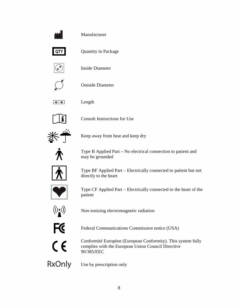
Manufacturer
Quantity in Package
Inside Diameter
Outside Diameter
Length
Consult Instructions for Use
Keep away from heat and keep dry
Type B Applied Part – No electrical connection to patient and may be grounded
Type BF Applied Part – Electrically connected to patient but not directly to the heart
Type CF Applied Part – Electrically connected to the heart of the patient
Non-ionizing electromagnetic radiation
Federal Communications Commission notice (USA)
Conformité Européne (European Conformity). This system fully complies with the European Union Council Directive 90/385/EEC
Use by prescription only
8

1.2 Introduction
This manual is intended to provide clinicians with information regarding the implant and use of the remedē® System. Included in this manual are descriptions of the remedē System as well as instructions for handling, storing and surgical placement of the remedē System. This manual also includes an overview of the remedē System therapy and instruction for clinical use and follow-up care of patients using the remedē System programmer.
1.3 Indications for Use
The remedē® System is an implantable phrenic nerve stimulator indicated for the treatment of moderate to severe central sleep apnea (CSA) in adult patients.
1.4 System Overview
The system consists of an implantable pulse generator (IPG), one transvenous lead to stimulate the phrenic nerve, and one transvenous sensing lead to sense respiration via transthoracic impedance. External, non-implanted devices and accessories of the remedē System include the remedē System programmer, external IPG, and programming wand.
1.5 Description of System Components
All implanted components of the remedē System are intended for single use only.
1.5.1 remedē® IPG
The remedē IPG (Model 1001, Figure 1) is an implantable, multi-programmable stimulator designed for unilateral, transvenous phrenic nerve stimulation. The device monitors the patient’s respiratory signals and provides electrical stimulation to the left or right phrenic nerve to restore patients to a normal breathing pattern during sleep. The remedē IPG contains electronic circuitry components and a battery, which are hermetically sealed in a titanium case. Therapy settings are determined by the physician and configured using an external programmer via telemetry.
The remedē IPG has four 3.2 mm connector ports (Figure 2) that are compatible with IS-1 connectors. The IS-1 lead connectors in each 3.2 mm connector port are secured by two set screws.
9

Figure 1 The remedē® System IPG
Figure 2 The remedē® IPG Connector Ports
1.5.2 respistim™ Stimulation Leads
Respicardia, Inc. has developed a respistim L (left) family of leads and a respistim R (right) family of leads for phrenic nerve stimulation to treat CSA. The respistim family of stimulation leads is comprised of four unique transvenous leads designed for chronic stimulation and sensing when placed in a thoracic vein and connected with a compatible pulse generator.
1.5.2.1 respistim™ L Stimulation Lead
The respistim L stimulation lead (Models 2001, 2002, 2003, and 2004) is a bipolar, transvenous, over-the-wire lead. The proximal end of the lead contains one IS-1 terminal pin/connector and the distal end is comprised of two ring electrodes. The lumen of the lead is continuous, permitting the passage of a 0.014” guide wire for delivery into the desired target vein.
1.5.2.2 respistim™ LQ Stimulation Lead
The respistim LQ stimulation lead (Models 5045, 5055, 5065, and 5085) is a quadripolar, transvenous, over-the-wire lead. The proximal end of the lead has two IS-1 terminal pins/connectors and the distal end is comprised of four ring electrodes. The lumen of the lead is continuous, permitting the passage of a 0.014” guide wire for delivery into the desired target vein.
10

1.5.2.3 respistim™ LQS Stimulation Lead
The respistim LQS stimulation lead (Models 4045, 4055, 4065, and 4085) is a quadripolar, transvenous, over-the-wire lead. The proximal end of the lead has two IS-1 terminal pins/connectors and the distal end is comprised of four ring electrodes having an S-shape bias. The lumen of the lead is continuous, permitting the passage of a 0.014” guide wire for delivery into the desired target vein.
1.5.2.4 respistim™ R Stimulation Lead
The respistim R stimulation lead (Models 3101, 3102, 3103, 3104, 3105, 3106 and 3201, 3202, 3203, 3204, 3205, 3206) is a hexapolar, transvenous, stylet delivered lead. The proximal end of the lead has three IS-1 terminal pins/connectors and the distal end of the lead is comprised of six ring electrodes and a non-electrically active tip having a helical shape bias. The lead is designed for use with a stylet to remove the distal bias and permit delivery of the lead into the desired target vein.
1.5.3 Respiratory Sensing Lead
The remedē System is designed to monitor respiration by sensing changes in transthoracic impedance. The system is capable of sensing respiration signals through either an implanted respistim stimulation lead or through a commercially available IS-1 compatible bipolar lead.
1.5.4 remedē® System Programmer
The remedē System programmer (Model 1002A, Figure 3) is a touch screen tablet computer used to communicate with the remedē implantable pulse generator (IPG) via inductive telemetry and allows for configuration of programmable settings, initiation of system testing and review of collected diagnostic data. Communication with the implanted device is achieved using the remedē programming software and an external programming wand (Model 1004A or 1004A-F) connected to the programmer via USB cable.
Figure 3 The remedē System Programmer
11

1.5.5 remedē® Programming Wand
The remedē System programming wands (Models 1004A, Figure 4 and 1004A-F) connect to the System programmer via USB and provide a magnetic inductive communication link to the implanted device. The Model 1004A programming wand requires placement of the wand directly over the implanted device for telemetry communication. The optional Model 1004A-F provides an extended flexible antenna disc that must be placed directly over the implanted device and is intended to allow for real-time monitoring during a polysomnogram (PSG).
Figure 4 The remedē Programming Wand (Model 1004A)
1.5.6 remedē® External IPG
The remedē external IPG (Model 1006, Figure 5) is used for evaluation of stimulation lead placement during implant of the remedē System. The external IPG (eIPG) delivers the same stimulation pulse as the remedē IPG and provides one set of anode and cathode connection ports for use with a sterile cable.
Figure 5 The remedē External IPG
1.6 Contraindications
The remedē System is contraindicated for the following:
• Patients with an active infection • Patients known to require magnetic resonance imaging (MRI)
12

1.7 Warnings and Precautions
Carefully read all warnings, precautions, and instructions before use. Follow all operating, maintenance, and installation procedures as described in this manual. Failure to do so may result in patient harm.
1.7.1 Warnings
1.7.1.1 Modified Components
The use of modified components with the remedē System is not allowed and may result in damaged components, unintended operation, or increased risks to the patient.
1.7.1.2 Magnetic Resonance Imaging (MRI or NMRI)
Do not use magnetic resonance imaging (MRI or NMRI) on patients who have been implanted with the remedē System. Energy produced by MRI equipment may result in permanent tissue damage or damage to the remedē System. Alternative imaging options should be considered.
1.7.1.3 Diathermy
Do not use shortwave diathermy, microwave diathermy or therapeutic ultrasound diathermy (collectively referred to as diathermy) on patients implanted with the remedē System. Energy produced by diathermy equipment may be transferred through the implanted system and can cause permanent tissue damage at the location of the implanted electrodes, resulting in severe injury or death.
Diathermy can also damage the remedē System, resulting in loss of therapy and requiring additional surgery for system explantation and replacement. Advise the patient to inform their health care professionals that diathermy exposure should be avoided.
1.7.1.4 Electric Shock
When operating under AC power, the remedē System programmer must be connected to a grounded power source to avoid risk of electric shock.
1.7.1.5 Concomitant Active Implantable Devices
Use remedē System with caution in patients with an active implantable device that may be susceptible to unintended interaction with the remedē system. Consult Respicardia to assess the possibility of interaction.
1.7.1.6 Patients with Evidence of Phrenic Nerve Palsy
Therapy with the remedē System may be ineffective in patients who have evidence of phrenic nerve palsy.
13

1.7.1.7 Pediatric Use
The safety and effectiveness of the remedē System has not been established for pediatric use.
1.7.1.8 Electromagnetic Compatibility and Medical Procedure Precautions
The remedē System is designed to ensure immunity from most common sources of electromagnetic interference (EMI). In most cases, turning off the EMI source, or moving away from the EMI source will return the IPG to normal operation. Extremely strong sources of EMI could interfere with normal IPG operation, causing the IPG to reset and requiring the programmed settings to be reconfigured. For information on MRI and diathermy, see ‘Warnings’ in sections 1.7.1.2 and 1.7.1.3.
1.7.1.8.1 Electrocautery
Electrocautery may induce failure of the IPG and leads if direct contact is made. Alternatives to electrocautery should be used when available. If electrocautery is necessary, the remedē System should be programmed off and bipolar cautery should be used. Confirm proper function of the remedē System after any procedure where electrocautery is used.
1.7.1.8.2 Radiofrequency or Cryoballoon Ablation
If radiofrequency or cryoballoon ablation must be used in the vicinity of the IPG or leads, the remedē System should be programmed off. Avoid direct contact between the radiofrequency ablation or cryoballoon catheter and the implanted remedē System.
1.7.1.8.3 Therapeutic Radiation
The IPG should not be directly irradiated by therapeutic levels of ionizing radiation (such as that produced by cobalt machines or linear accelerators used for treatment of certain cancers) because of the risk for damage to the remedē System. If such therapy is required, program the remedē System off, shield the device, and confirm proper function of the remedē System after treatment.
1.7.1.8.4 Computed Tomography (CT) Imaging
If a CT scan is required, ensure that the remedē System is off and confirm proper function of the remedē System after the scan is complete.
1.7.1.8.5 Therapeutic Ultrasound
Exposure to high ultrasonic frequencies may result in damage to the remedē System. It is not recommended to use high-output ultrasonic devices, such as an electrohydraulic lithotripter or bone growth simulator on patients implanted with the remedē System. If therapeutic ultrasound must be performed, program the remedē System off and keep the implanted system a minimum of 2.5 cm (1 in) away from the ultrasonic field. Confirm proper function of the remedē System after treatment.
14

1.7.1.8.6 External Defibrillation Energy
The use of external defibrillation may cause damage to the remedē System. The risk of damage may be minimized by positioning the defibrillation patches or paddles a minimum of 15 cm (6 in) and perpendicular to the IPG. Confirm proper function of the remedē System after any use of external defibrillation.
1.7.1.8.7 Patient Monitoring Equipment
remedē System stimulation therapy may be detectable by patient monitoring equipment including automated external defibrillators. Confirm proper function of monitoring equipment if used while remedē stimulation therapy is active.
1.7.1.8.8 Transcutaneous Electrical Nerve Stimulators (TENS)
TENS therapy should be used only if the remedē System is inactive (not providing stimulation therapy). If TENS therapy must be used, place the TENS electrodes as far from the remedē System as possible. TENS electrodes should also be spaced as close together as possible to reduce the generated electrical field. Confirm proper function of the remedē System after use of TENS therapy.
1.7.1.8.9 Electrical Isolation During Implant
Do not allow the patient to have contact with grounded equipment that might produce electrical current leakage during implant. Electrical current leakage may induce arrhythmias that could result in patient death.
1.7.1.8.10 Lead Compatibility
Only use IS-1 lead or lead extension terminals with the remedē System. Use of non IS-1 compatible terminals may result in undersensing of respiratory activity, failure to deliver necessary therapy, or a leaking or intermittent electrical connection.
1.7.1.8.11 Concomitant Active Implantable Cardiac Devices
It is recommended that testing for oversensing of remedē stimulation therapy by the concomitant cardiac device occur at the time of implant and prior to initiating remedē System therapy in patients with a concomitantly implanted cardiac device (testing protocol described on page 37). Programming of the remedē System and/or the concomitant device, when necessary, can prevent oversensing of remedē stimulation therapy.
To avoid telemetry interference, one telemetric programming system should be utilized at a time if the concomitantly implanted device uses magnetic inductive telemetry.
15

1.7.1.9 Pacemaker Dependence
Use remedē System therapy with caution in pacemaker dependent patients without a physiologic escape rhythm. Device interaction may lead to over or undersensing resulting in a loss of pacing.
1.7.1.10 Pregnancy
The safety and effectiveness of the remedē System during pregnancy has not been established.
1.7.2 General Precautions
1.7.2.1 Expiration Date
Do not use any remedē System product after its expiration date.
1.7.2.2 Storage Temperature Ranges
It is recommended the remedē System be stored in a dry place according to the temperature ranges below:
remedē System Temperature Ranges remedē IPG 0ºC (32ºF) and 50ºC (122ºF) respistim R, L, LQ, LQS Leads 5ºC (41ºF) and 30ºC (86ºF) remedē System Programmer -20ºC (-4ºF) and 70ºC (158ºF) Programming Wand -20ºC (-4ºF) and 70ºC (158ºF) eIPG 0ºC (32ºF) and 50ºC (122ºF)
1.7.3 Home or Work Environment Precautions
1.7.3.1 High Powered Electric Fields
Normal operation of the remedē System can be affected by magnetic, electrical and electromagnetic signals with sufficient strength or with characteristics similar to respiratory activity. Consult with Respicardia if the patient will be in an area where contact with current carrying conductors is possible or near high powered electromagnetic fields caused by equipment such as arc welding units, induction furnaces, induction stoves, resistance welders, radio or microwave transmitters, and linear power amplifiers.
1.7.3.2 Cellular Phones
Normal operation of the remedē System may be affected by cellular phones. Maintain a minimum separation of 25 cm (10 in) between a cellular phone and the remedē System, even if the cellular phone is not on.
16

1.7.3.3 Electronic Article Surveillance (EAS)
Electronic article surveillance equipment such as retail theft prevention systems, as well as airport metal detectors, may interfere with the remedē System. Advise patients to walk directly through an EAS system and not remain near an EAS system longer than necessary. Where possible, alert security personnel of the implanted remedē System and request a manual search.
1.7.3.4 Common Radiofrequency Sources (e.g. RFID)
Normal operation of the remedē System may be affected by common radiofrequency sources. Patients should minimize time around radiofrequency sources, such as RFID, when recognized they are nearby and operators of the remedē System external components should maintain a separation distance of 40cm from RFID systems.
1.7.3.5 Static Magnetic Fields
Patients should avoid equipment or situations where they would be exposed to static magnetic fields greater than 10 gauss or 1 mT. Static magnetic fields may suspend therapy until next scheduled therapy session. Sources of static magnetic fields include, but are not limited to, stereo speakers, bingo wands, extractor wands, magnetic badges, or magnetic therapy products.
1.7.3.6 Wi-Fi
Do not use or enable Wi-Fi on the remedē System programmer to protect the system from cybersecurity risks.
1.7.4 remedē® System Therapy Hazards
1.7.4.1 Risk of Arrhythmia
The stimulation lead should be placed in the right brachiocephalic vein or the left pericardiophrenic vein. Based on clinical study of leads placed in these locations, it is highly unlikely the heart would be electrically impacted by the levels of stimulation available in the remedē System (≤10 mA, 300 µs). Based on clinical experience and animal testing experience with displaced leads, it is unlikely that a displaced lead would cause significant arrhythmias.
1.7.4.2 Muscle Stimulation in Unipolar Configuration
Under certain circumstances, such as high-output unipolar stimulation, therapy induced muscle stimulations may occur at the pocket site of the implanted device. This condition is mitigated by appropriate programming of the stimulation parameters by qualified medical personnel in conjunction with patient feedback.
17

1.7.4.3 Component Failure
As with any active implantable electronic system, the remedē System might unexpectedly fail or stop working at any time due to random component fault, battery failure, exposure to extreme environmental interferences or environmental conditions. These factors may reduce system longevity, effectiveness and cause change in the performance characteristics.
1.8 Adverse Effects
Possible adverse effects include, but are not limited to, the following:
Implant Procedure-Related • Adverse contrast dye reaction such as allergic reaction, pulmonary edema, or
worsening renal function • Adverse reaction to radiation exposure • Thromboembolism • Air embolism • Bleeding • Cardiac perforation including tamponade • Hematoma, seroma, local bruising or swelling • Hypotension • Local wound healing issues at device implant site including wound
dehiscence, pocket erosion, extrusion, movement of implanted device, keloid formation
• Pneumothorax • Hemothorax • Vascular damage, e.g., venous dissection, perforation Lead and System-Related • Adverse biocompatibility reaction to the implanted system • Infection • Lead breakage • Lead dislodgement • Lead not connected or secured appropriately in device header • Implantable device malfunction • Requirement for more energy to stimulate the nerve or ineffective stimulation • Venous occlusion Therapy-Related • Crosstalk with another implanted device
18

• Disrupted sleep • Muscle fatigue or discomfort in diaphragm, chest or abdomen from
appropriate stimulation • Nerve dysfunction • Perturbation of blood gases causing hypoxia, hypercapnea and/or hypocapnea • Inappropriate sensations • Worsening heart failure, respiratory status or overall health Other Procedure, System or Therapy-Related • Anxiety • Arrhythmia, including ventricular fibrillation • Death • Depression • Hypotension • Pain • Skin irritation or local allergic reaction • Thrombus or embolism, potentially leading to pulmonary embolism or stroke
1.9 Clinical Data Summary 1.9.1 Pivotal Trial of the remedē System
The remedē System was evaluated in a prospective, multicenter, randomized trial at study centers in the United States, Germany, and Poland for the indication of transvenous stimulation of the phrenic nerve for the treatment of central sleep apnea (CSA).
1.9.2 Patients Studied
The study enrolled 151 central sleep apnea patients who underwent an implant procedure. Of the 151 implant attempts, 147 (97%) were successful. The study endpoints were evaluated based on intent to treat. The patient demographics for the remedē System Pivotal Trial are included in Table 1.
19
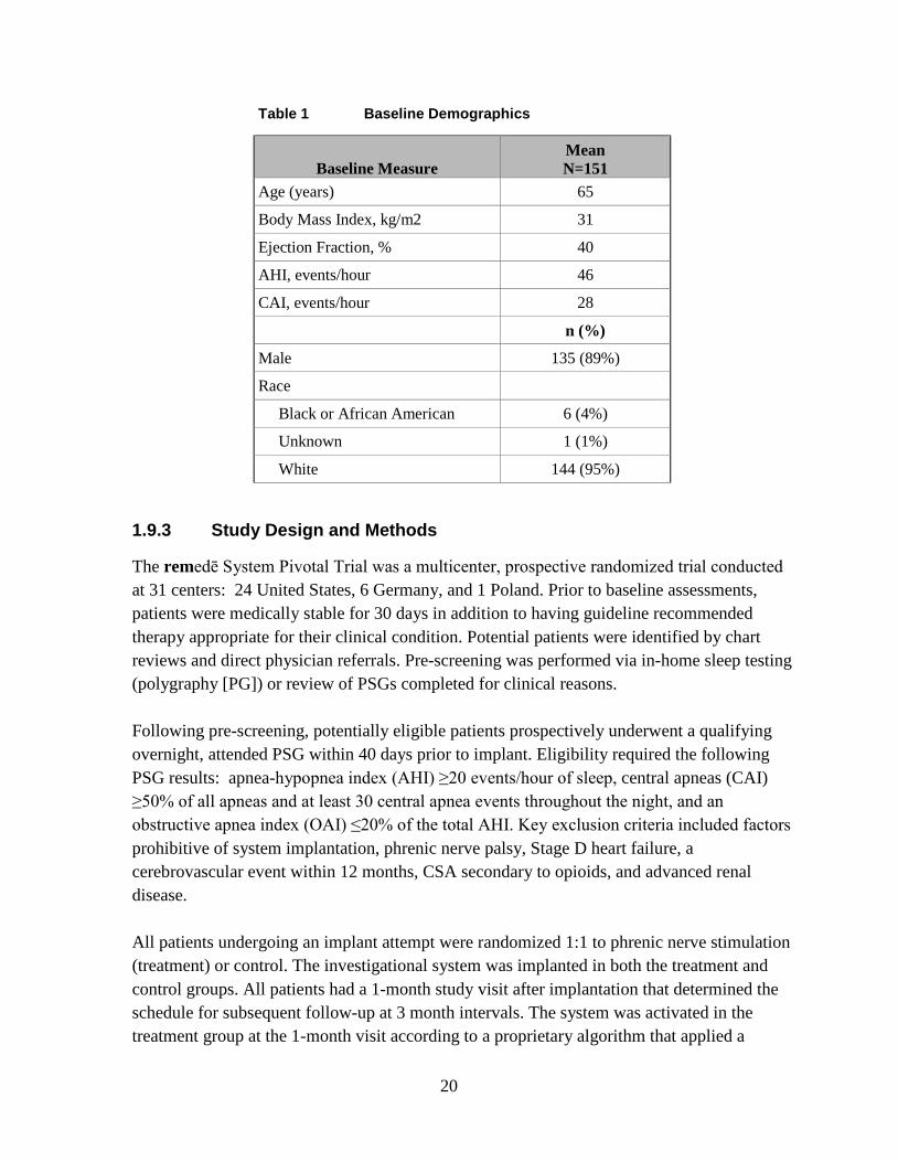
Table 1 Baseline Demographics
Baseline Measure Mean N=151
Age (years) 65
Body Mass Index, kg/m2 31
Ejection Fraction, % 40
AHI, events/hour 46
CAI, events/hour 28
n (%)
Male 135 (89%)
Race
Black or African American 6 (4%)
Unknown 1 (1%)
White 144 (95%)
1.9.3 Study Design and Methods
The remedē System Pivotal Trial was a multicenter, prospective randomized trial conducted at 31 centers: 24 United States, 6 Germany, and 1 Poland. Prior to baseline assessments, patients were medically stable for 30 days in addition to having guideline recommended therapy appropriate for their clinical condition. Potential patients were identified by chart reviews and direct physician referrals. Pre-screening was performed via in-home sleep testing (polygraphy [PG]) or review of PSGs completed for clinical reasons. Following pre-screening, potentially eligible patients prospectively underwent a qualifying overnight, attended PSG within 40 days prior to implant. Eligibility required the following PSG results: apnea-hypopnea index (AHI) ≥20 events/hour of sleep, central apneas (CAI) ≥50% of all apneas and at least 30 central apnea events throughout the night, and an obstructive apnea index (OAI) ≤20% of the total AHI. Key exclusion criteria included factors prohibitive of system implantation, phrenic nerve palsy, Stage D heart failure, a cerebrovascular event within 12 months, CSA secondary to opioids, and advanced renal disease. All patients undergoing an implant attempt were randomized 1:1 to phrenic nerve stimulation (treatment) or control. The investigational system was implanted in both the treatment and control groups. All patients had a 1-month study visit after implantation that determined the schedule for subsequent follow-up at 3 month intervals. The system was activated in the treatment group at the 1-month visit according to a proprietary algorithm that applied a
20

stimulation pattern which enabled full diaphragmatic contraction while the patient continued to sleep. A full night PSG was completed 6 months following the 1 month visit in all subjects to assess the primary effectiveness endpoint. The system remained off in the control group through the 6-month effectiveness assessment, after which therapy was initiated and remained on. The primary effectiveness endpoint was a comparison of the proportions of patients in the treatment versus control groups achieving a reduction in AHI of ≥50% from baseline to 6 months. The primary safety endpoint was freedom from serious adverse events associated with the implantation procedure, the system, or delivered therapy in the combined study groups through 12 months. A serious adverse event was defined as any adverse event that led to death, led to a serious deterioration in the health of the subject, resulted in a life-threatening illness or injury, resulted in a permanent impairment of a body structure or a body function, required inpatient hospitalization or prolongation of existing hospitalization, resulted in medical or surgical intervention to prevent permanent impairment to a body structure or a body function , or led to fetal distress, fetal death or a congenital abnormality or birth defect.
1.9.4 Study Results
1.9.4.1 Safety
1.9.4.1.1 Primary Safety Endpoint
The percentage of subjects free from serious adverse events (SAE) associated with the implant procedure, the remedē system, or the delivered therapy through the 12 month visit was 91% [95% exact CI (86%, 95%)]. No statistical hypothesis testing was performed on this endpoint (Table 2).
Table 2 Summary of Freedom from Related SAEs through 12 Month Visit (ITT)
Variable Pooled1 (N=151 )
Freedom from related SAEs 91% (138) (86%, 95%)
1 Percent (n) and 95% exact confidence interval. Thirteen subjects (9%) each reported a single implant procedure, remedē System, or delivered therapy related SAE. Table 3 displays the number of each type of event reported, along with the number and percentage of subjects who experienced the event.
21

Table 3 Summary of Serious Adverse Events by Relation to Implant Procedure, remedē System, or Delivered Therapy through 12 Months
Pooled (N=151)
Implant, System and/or Therapy
Related1,2
Implant Procedure
Related System Related Delivered
Therapy Related
Event n
Events % (n)
Subjects n
Events % (n)
Subjects n
Events % (n)
Subjects n
Events % (n)
Subjects
ANY EVENT 13 9% (13) 9 6% (9) 6 4% (6) 2 1% (2)
IMPENDING POCKET EROSION
2 1% (2) 1 1% (1) 1 1% (1) 0 0% (0)
IMPLANT SITE INFECTION 2 1% (2) 2 1% (2) 0 0% (0) 0 0% (0)
LEAD DISLODGEMENT 2 1% (2) 2 1% (2) 2 1% (2) 0 0% (0)
CONCOMITANT DEVICE INTERACTION
1 1% (1) 0 0% (0) 1 1% (1) 1 1% (1)
ELEVATED TRANSAMINASE 1 1% (1) 1 1% (1) 0 0% (0) 0 0% (0)
EXTRA-RESPIRATORY STIMULATION
1 1% (1) 0 0% (0) 0 0% (0) 1 1% (1)
IMPLANT SITE HEMATOMA 1 1% (1) 1 1% (1) 0 0% (0) 0 0% (0)
LEAD COMPONENT FAILURE 1 1% (1) 0 0% (0) 1 1% (1) 0 0% (0)
LEAD DISPLACEMENT 1 1% (1) 1 1% (1) 1 1% (1) 0 0% (0)
NON-CARDIAC CHEST PAIN 1 1% (1) 1 1% (1) 0 0% (0) 0 0% (0) 1Relationship defined as probably or definitely related. 2Events and subjects with events may be counted as implant procedure, system and therapy related so may not add up to the combined events or subjects.
22

1.9.4.1.2 Non-Serious Related Adverse Events
Forty-eight percent (48%) of subjects experienced a non-serious event related to the implant procedure, the remedē System or delivered therapy. Table 4 displays the number of each type of event reported, the number and percentage of subjects who experienced the events, and the relationship of the event to the implant procedure, the remedē System or delivered therapy.
23

Table 4 Summary of Related non-Serious Adverse Events and Observations through 12 Months Pooled (N=151)
Implant, System and/or Therapy
Related1,2 Implant Procedure
Related System Related Delivered Therapy
Related
EVENT n Events % (n)
Subjects n Events % (n)
Subjects n Events % (n)
Subjects n Events % (n)
Subjects
ANY EVENT 105 48% (73) 30 17% (25) 11 7% (11) 67 35% (53)
DIAPHRAGMATIC STIMULATION DISCOMFORT
48 25% (38) 0 0% (0) 1 1% (1) 48 25% (38)
EXTRA-RESPIRATORY STIMULATION
15 9% (14) 0 0% (0) 0 0% (0) 15 9% (14)
IMPLANT SITE PAIN 7 5% (7) 7 5% (7) 0 0% (0) 0 0% (0)
IMPLANT SITE HEMATOMA 5 3% (4) 5 3% (4) 0 0% (0) 0 0% (0)
IMPLANT SITE BRUISING 4 3% (4) 4 3% (4) 0 0% (0) 0 0% (0)
ELEVATED LEAD IMPEDANCE 3 2% (3) 1 1% (1) 3 2% (3) 0 0% (0)
ELEVATED THRESHOLDS 2 1% (2) 0 0% (0) 2 1% (2) 0 0% (0)
IMPLANT SITE INFLAMMATION 2 1% (2) 2 1% (2) 0 0% (0) 0 0% (0)
INSOMNIA 2 1% (2) 0 0% (0) 0 0% (0) 2 1% (2)
PROGRAMMING ERROR 2 1% (2) 0 0% (0) 1 1% (1) 1 1% (1)
VENOUS THROMBOSIS 2 1% (2) 0 0% (0) 2 1% (2) 0 0% (0)
BACK PAIN 1 1% (1) 1 1% (1) 0 0% (0) 0 0% (0)
CONCOMITANT DEVICE INTERACTION
1 1% (1) 0 0% (0) 0 0% (0) 1 1% (1)
DIARRHEA 1 1% (1) 1 1% (1) 0 0% (0) 0 0% (0)
24

Pooled (N=151)
Implant, System and/or Therapy
Related1,2 Implant Procedure
Related System Related Delivered Therapy
Related
EVENT n Events % (n)
Subjects n Events % (n)
Subjects n Events % (n)
Subjects n Events % (n)
Subjects
DISSECTION OF SUBCLAVIAN VEIN
1 1% (1) 1 1% (1) 0 0% (0) 0 0% (0)
HYPOXIA 1 1% (1) 1 1% (1) 0 0% (0) 0 0% (0)
IMPLANT SITE ERYTHEMA 1 1% (1) 1 1% (1) 0 0% (0) 0 0% (0)
IMPLANT SITE INFECTION 1 1% (1) 1 1% (1) 0 0% (0) 0 0% (0)
IMPLANT SITE SWELLING 1 1% (1) 1 1% (1) 0 0% (0) 0 0% (0)
INADEQUATE LEAD POSITION 1 1% (1) 1 1% (1) 0 0% (0) 0 0% (0)
LEAD DISLODGEMENT 1 1% (1) 1 1% (1) 1 1% (1) 0 0% (0)
LEAD DISPLACEMENT 1 1% (1) 0 0% (0) 1 1% (1) 0 0% (0)
SUTURE IRRITATION 1 1% (1) 1 1% (1) 0 0% (0) 0 0% (0)
URTICARIA 1 1% (1) 1 1% (1) 0 0% (0) 0 0% (0) 1Relationship defined as probably or definitely related. 2Events and subjects with events may be counted as implant procedure, system and therapy related so may not add up to the combined events or subjects.
25

1.9.4.1.3 System Explants
Explants of the remedē System occurred in 5.3% (8/151) of subjects. Details are provided in Table 5.
Table 5 Summary of System Explants
Number of Subjects Reason for System Explant
2 Investigational device implant site infection 2 Elective explant1 1 Device battery depletion – expected 1 Lead component failure2
1 ICD pocket infection (ICD and remedē System shared a common venous entry point requiring explant of both systems)
1 Failed stimulation lead modification procedure 1One subject chose to exit due to an intervening medical condition (depression) and one subject withdrew consent and requested a system explant 2 Failure of one constituent part of the lead
1.9.4.1.4 Trial Withdrawals
A total of 43 subjects had exited the trial as of the datalock. Table 6 displays the reasons for trial discontinuation.
Table 6 Summary of Reasons for Trial Withdrawals
Treatment
(N=73) Control (N=78)
Pooled (N=151)
Exit reason % (n) Subjects % (n) Subjects % (n) Subjects Physician-initiated withdrawal 1% (1) 3% (2) 2% (3)
Subject Death 15% (11) 14% (11) 15% (22)
Subject Lost to Follow-Up 1% (1) 1% (1) 1% (2)
Subject-initiated withdrawal 8% (6) 5% (4) 7% (10)
System explanted1 7% (5) 1% (1) 4% (6)
Total 33% (24) 24% (19) 28% (43) 12 subject-initiated withdrawals also underwent system explant
Subjects exited for the following reasons:
• Physician-initiated withdrawals for three (3) subjects
o Two (2) due to intervening medical conditions
o One (1) exit from the trial subsequent to a failed implant attempt
26

• Subject death for 22 subjects
• Lost to follow-up for two (2) subjects
o One (1) subject after an unsuccessful implant attempt
o One (1) subject became unreachable despite multiple attempts by the investigational site to contact the subject
Note: Neither subject had therapy initiated at the time of being lost to follow-up
• Subject-initiated withdrawals for ten (10) subjects
o Four (5) subjects withdrew due to intervening medical issues
o Three (3) subjects withdrew due to relocating away from study site
o Two (2) withdrew consent subsequent to failed implant attempts
• Withdrawal due to explanted remedē Systems occurred in six (6) subjects. Two (2) subject-initiated withdrawals also had the system explanted as outlined in Section 1.9.4.1.3
27

1.9.4.2 Effectiveness
The primary effectiveness endpoint was a comparison of the proportions of patients in the treatment versus control groups achieving a reduction in AHI of ≥50% from baseline to 6 months. The proportion of patients achieving ≥ 50% reduction in AHI and the 95% confidence interval (CI) for the Treatment group was 51% (35/68) [95% CI (39%, 64%)] compared to 11% (8/73) [95% CI (5%, 20%)] for the Control group, resulting in a difference of 41% [95% CI (25%, 54%)] (Table 7). This result was statistically significant (p<.0001), demonstrating that active therapy with the remedē System is superior to Control (inactive therapy) in achieving a 50% reduction in AHI.
Table 7 Summary of the Comparison of the Proportion of Patients with ≥ 50% Reduction in AHI at 6 Months (Modified ITT)
Variable Treatment1 Control Difference P-value2
AHI reduced ≥ 50% 51% (35/68) (39%, 64%)
11% (8/73) (5%, 20%)
41% (25%, 54%)
<.0001
Percent (n/N) and 95% Exact Confidence Interval. 1Includes 7 patients imputed as not achieving ≥ 50% reduction in AHI. 2 P-value from 1-sided Fisher’s Exact Test.
1.9.4.3 Conclusion
The data support the reasonable assurance of safety and effectiveness of this device for treatment of moderate to severe CSA in adults.
1.10 Storage and Handling
Respicardia sterilizes the IPG and stimulation leads with ethylene oxide (EtO) prior to shipment.
The materials used are biologically compatible, but they are nevertheless prone to attract foreign particles. Avoid any contamination before introduction of the IPG or leads into the body.
Inspect the sterile package and contents prior to opening to ensure it is intact and contains a proper sterile use by date. The IPG, stimulation leads, and packaged accessories are intended for one (1) time use only and cannot be resterilized, do not implant product from a damaged or opened package.
Store and transport the remedē System in a dry place and within the recommended environmental temperature limits displayed in Table 8 below.
28
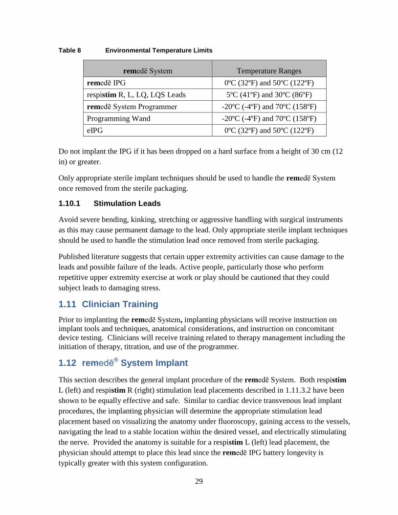
Table 8 Environmental Temperature Limits
remedē System Temperature Ranges remedē IPG 0ºC (32ºF) and 50ºC (122ºF) respistim R, L, LQ, LQS Leads 5ºC (41ºF) and 30ºC (86ºF) remedē System Programmer -20ºC (-4ºF) and 70ºC (158ºF) Programming Wand -20ºC (-4ºF) and 70ºC (158ºF) eIPG 0ºC (32ºF) and 50ºC (122ºF)
Do not implant the IPG if it has been dropped on a hard surface from a height of 30 cm (12 in) or greater.
Only appropriate sterile implant techniques should be used to handle the remedē System once removed from the sterile packaging.
1.10.1 Stimulation Leads
Avoid severe bending, kinking, stretching or aggressive handling with surgical instruments as this may cause permanent damage to the lead. Only appropriate sterile implant techniques should be used to handle the stimulation lead once removed from sterile packaging.
Published literature suggests that certain upper extremity activities can cause damage to the leads and possible failure of the leads. Active people, particularly those who perform repetitive upper extremity exercise at work or play should be cautioned that they could subject leads to damaging stress.
1.11 Clinician Training Prior to implanting the remedē System, implanting physicians will receive instruction on implant tools and techniques, anatomical considerations, and instruction on concomitant device testing. Clinicians will receive training related to therapy management including the initiation of therapy, titration, and use of the programmer.
1.12 remedē® System Implant
This section describes the general implant procedure of the remedē System. Both respistim L (left) and respistim R (right) stimulation lead placements described in 1.11.3.2 have been shown to be equally effective and safe. Similar to cardiac device transvenous lead implant procedures, the implanting physician will determine the appropriate stimulation lead placement based on visualizing the anatomy under fluoroscopy, gaining access to the vessels, navigating the lead to a stable location within the desired vessel, and electrically stimulating the nerve. Provided the anatomy is suitable for a respistim L (left) lead placement, the physician should attempt to place this lead since the remedē IPG battery longevity is typically greater with this system configuration.
29

1.12.1 Mitigation Strategies for Managing the Risk of Infection During remedē System Implant, Replacement and Explant Procedures
The following recommendations should be followed in order to minimize the risk of infection during the remedē System implant, replacement and explant procedures.
• Use rigorous aseptic methods including antiseptic skin preparation • Administer prophylactic and post-operative antibiotics • Use antiseptic flush in the pocket • Use local antimicrobial agents
1.12.2 Implantable System
• remedē System IPG • respistim L, LQ, LQS, or R stimulation lead • IS-1 compatible bipolar transvenous lead for sensing
1.12.3 remedē® System Implant Procedure
The remedē System Implant includes the following steps:
• Locate target vessel and deploy the stimulation lead
• Test for phrenic nerve capture and secure the stimulation lead
• Deploy the sensing lead
• Perform final testing
• Create pocket, insert leads into the IPG and secure the IPG in the pocket
• Concomitant testing (if applicable)
1.12.3.1 Locate the Target Vessel
• Gain venous access using the right axillary, cephalic or subclavian vein using standard techniques.
• Select a puncture site near the lateral border of the first rib when utilizing a subclavian approach and avoid penetrating the subclavius muscle
Caution: Do not insert the lead under the medial one-third region of the clavicle; lead damage from clavicle/first rib entrapment or chronic dislodgment of the lead is possible if the lead is implanted in this manner. It is recommended to introduce the lead into the subclavian vein near the lateral border of the first rib.
• Insert a guiding catheter and position within the left brachiocephalic vein. Refer to Figure 6 below for a pictorial description of typical venous anatomy.
30

• Obtain a venogram to visualize target vein ostium.
Caution: When locating the target vein ostium with the guiding catheter, do not force the catheter tip forward if resistance is felt.
Caution: Excessive amount and/or rate of contrast dye injection can cause extravasation of contrast dye or vessel dissection.
• Cannulate the vein and visualize with selective venogram (for the left pericardiophrenic vein).
Figure 6 Typical Left Pericardiophrenic Vein Anatomy
1.12.3.2 Deploy the Left or Right Stimulation Lead
1.12.3.2.1 Left Pericardiophrenic Stimulation Lead
• Insert respistim L, LQ, or LQS stimulation lead over a 0.014 inch guide wire and advance to desired position within the left pericardiophrenic vein
• Use care when inserting a guide wire into the lead to avoid penetrating the lead wall or damaging the lead conductor coil. Note: Flushing a clotted lead can compromise the integrity of the stimulation lead. If clotting is suspected, remove the lead from the body and soak in heparinized saline. Insert a guide wire into the proximal or distal end of the stimulation lead and advance to clear the lumen.
Note: Guide wires should be handled with care at all times. A damaged guide wire may not behave as expected and could result in damage to the lead or vasculature.
31

1.12.3.2.2 Right Brachiocephalic Stimulation Lead
• Select the appropriate right stimulation lead model for the diameter of the brachiocephalic vein (See Appendix III). A lead that is too small for the vessel can result in weak or ineffective diaphragmatic stimulation
• Ensure the stylet is fully advanced within the lead to the distal end of the lumen before inserting the right stimulation lead
• Use care when inserting the stylet to avoid damaging the lead wall or conductor coil. It may be necessary to straighten the helical shape of the lead to fully advance the stylet
• Place the lead through an introducer sheath and advance until the distal end of the lead is at the level of the superior vena cava or right atrium
• Retract the stylet gradually and apply counterclockwise rotation to the lead body to allow the helical shape to form
• Apply gentle traction and counterclockwise rotation as needed to position the electrodes along the lateral wall of the vessel
• Do not allow the proximal and distal helixes to collapse and make contact as this will not provide a stable lead position
• Assess the stability of the lead position by requesting that the patient breathe deeply or cough during fluoroscopic observation
Note: Motion of the lead synchronous with cardiac systole may suggest that the lead is near the right atrium and should be repositioned.
1.12.3.3 Test for Phrenic Nerve Capture
Patient stimulation testing requires communication with the patient to ensure an appropriate stimulation response. Physicians should deliver procedural sedation that allows for this communication. See Table 9 below for recommended stimulation threshold and impedance values.
• Evaluate stimulation lead impedance • Perform stimulation threshold testing
o Once the stimulation lead has been placed in the desired location, make sure the stylet or guide wire is retracted sufficiently to expose lead bias, if applicable, allowing the lead to engage the vessel in a natural way.
o Select an electrode testing configuration (cathode-anode electrode pair) and connect the stimulation lead to the remedē eIPG
Caution: Connect the sterile cable to the remedē eIPG before connecting to the stimulation lead.
32

Caution: Do not touch the exposed metal of the stimulation lead connector end or the exposed metal of the cable alligator clips. Do not allow the exposed metal of the stimulation lead connector end or the exposed metal of the cable alligator clips to contact electrically conductive or wet surfaces.
Caution: Protect any unused alligator clip(s) from contact with any conductive surface or current leakage source.
o Set the eIPG stimulation amplitude, pulse width and frequency based on the stimulation lead implanted respistim L (left) stimulation lead
• Amplitude = 2 mA • Pulse Width = 150 µsec • Frequency = 20 Hz
respistim R (right) stimulation lead • Amplitude = 5 mA • Pulse Width = 300 µsec • Frequency = 40 Hz
o Deliver a single test pulse o Increase or decrease the stimulation current incrementally as needed until a
moderately strong diaphragmatic contraction is observed by means of abdominal palpation or fluoroscopic visualization If an inadequate response or no response is detected, the implanting
physician should select a new electrode pair (for R, LQ and LQS leads) and repeat the stimulation threshold test before repositioning the stimulation lead
If an inadequate or no response persists, the stimulation lead should be repositioned and the stimulation threshold test sequence repeated until the desired response is achieved
o Test for extra respiratory sensations (ERS) at levels above the stimulation threshold ERS or sensations during stimulation other than diaphragmatic
contraction are the result of stimulating nerves beyond the phrenic nerve
Reposition the lead if unable to avoid ERS through electrode selection or limitation of IPG output
Table 9 Recommended Stimulation Threshold and Impedance Values
33

Stimulation Lead
Stimulation Threshold
Stimulation Lead
Impedance
Criteria for stimulation threshold
Left <4mA 400 – 2000 Ω Clear evidence of diaphragmatic movement determined via palpation or fluoroscopy Right <5mA 200 – 800 Ω
1.12.3.4 Secure the Stimulation Lead
• The guiding catheter (respistim L, LQ or LQS) or introducer sheath (respistim R) must be removed prior to securing the stimulation lead. For detailed instructions on removing the guiding catheter refer to the manufacturer’s Instructions For Use (IFU).
• Ensure sufficient lead slack is provided within the venous system to allow for strain relief during changes in body position to reduce the risk of lead dislodgement.
• Position the first ligature sleeve immediately proximal to the point of venous access and secure the ligature sleeve to the lead using permanent, non-absorbable sutures; anchor the ligature sleeve to the fascia or other suitable subcutaneous tissue using permanent, non-absorbable sutures.
• For respistim R leads, place a second suture sleeve a minimum of 10 cm proximal to the first suture sleeve with a strain relief loop between the first and second sleeve for stability.
• Maintain the guide wire or stylet within the lumen of the stimulation lead while securing the ligature sleeve to the lead body and anchoring to tissue in order to prevent damage to the stimulation lead insulation and conductor coil.
• Do not use excessive force when tying sutures on ligature sleeves. • Do not kink, twist, or torque the lead while anchoring the ligature sleeve, as doing so
could cause electrode movement. • Do not tie a suture directly to the lead body. Note: Inadequate strain relief between proximal and distal ligature sleeves (if multiple ligature sleeves are present) or between ligature sleeve and IPG pocket can increase the risk of chronic flex damage to the lead.
1.12.3.5 Deploy Sensing Lead
• Deploy the sensing lead into a branch vein off the main tributary of the azygos vein using standard techniques
Note: The respistim lead or any commercially available bipolar IS-1 compatible lead can be utilized for sensing
34

1.12.3.6 Create Pocket, Insert Leads and Secure IPG
Note: For optimal performance of the 3-axis position sensor, care should be taken to ensure the pocket is tight forming and aligned vertically (Figure 7).
Figure 7 Recommended IPG Pocket Location
The remedē IPG has four IS-1 bipolar connector ports in the header block, three for connecting stimulation leads and one for a sensing lead. The three stimulation lead ports are labeled 1-2, 3-4 and 5-6 corresponding to the following stimulation lead electrodes (Figure 8). The single IS-1 bipolar connector sensing lead port is labeled S and allows for the insertion of a bipolar sensing lead (also Figure 8):
Figure 8 The remedē IPG Connector Block and Port Diagram
1-2 corresponds to electrode 1 (distal) and electrode 2
3-4 corresponds to electrode 3 and electrode 4
5-6 corresponds to electrode 5 and electrode 6 (proximal)
S corresponds to the sensing lead
35

Note: For easier lead insertion, insert terminal S into Sense IS-1 and lower stimulation port (5-6) IS-1 connectors first.
The distal end electrodes of the respistim L Stimulation Lead correspond to the IS-1 connections detailed in Figure 9 with electrode 1 being the most distal electrode and electrode 2 being the most proximal electrode.
1 2
Figure 9 respistim L Stimulation Lead Connections
The electrodes of the respistim LQ and LQS Stimulation Leads correspond to the IS-1 connections shown in Figure 10 with electrode 1 being the most distal electrode and electrode 4 being the most proximal electrode. The IS-1 terminal containing the serial number marking corresponds to electrode 1-2.
1 2
3 4
Serial #
Figure 10 respistim LQ and LQS Stimulation Lead Connections
The electrodes of the respistim R Stimulation Leads correspond to the IS-1 connections shown in Figure 11 with electrode 1 being the most distal electrode and electrode 6 being the most proximal electrode. The IS-1 terminal containing the serial number marking corresponds to electrode 1-2.
1 2
3 4
6
Serial #
5
Figure 11 respistim R Stimulation Lead Connections
36

Caution: Verify that the lead connections are secure. Loose lead connections may result in inappropriate sensing and/or failure to deliver stimulation therapy.
Caution: Use only the wrench supplied with the device. The wrench is designed to prevent damage to the device from over tightening a setscrew.
Caution: Counterclockwise rotation of a set screw may cause the set screw to disengage from the connector block.
Caution: If a multipolar stimulation lead is not implanted, pin plugs provided with the device must be secured in the unused stimulation ports to avoid damage to the device.
• Do not kink, twist, or braid the lead connectors with other leads, as doing so could cause lead insulation abrasion or conductor damage.
• Do not bend the lead near the lead-header interface. Improper insertion can cause insulation or connector damage.
• Prior to placing the IPG in the pocket, wrap any excess lead length loosely behind the IPG by rotating as shown in Figure 12.
• Place the IPG and excess lead wrap in the IPG pocket with the IPG connector closest to the pocket incision and with the device labeling facing up toward the skin.
• Do not coil the leads. Coiling will twist the lead bodies and may result in lead dislodgment.
Figure 12 Proper Rotation of IPG to Wrap Excess Lead Length
• Test lead impedance after connecting the leads to the IPG • Secure the remedē IPG in the pocket in order to minimize the risk of migration and
mechanical interaction with the lead
1.12.4 Concomitant Cardiac Device Testing (if applicable)
Testing for concomitant cardiac device interaction at the time of remedē System implant for patients with a pre-existing cardiac device is recommended. Concomitant device interaction testing should be repeated prior to therapy initiation and anytime the remedē System or the cardiac device system is modified. The following steps are required to complete concomitant device interaction testing:
37

1. Disable high voltage cardiac therapies on the cardiac device if applicable 2. Program cardiac device sensing to the most sensitive setting and prepare for
monitoring electrogram (EGM) and device marker channels 3. Set up remedē System stimulation test (2 sec duration)
a. Acute/new remedē System: i. Left stimulation lead: pulse width 150ms, frequency 20 Hertz
ii. Right stimulation lead: pulse width 300ms, frequency 40 Hertz b. Chronic remedē System:
i. Use programmed pulse width and frequency settings 4. Deliver 2-3 stimulation pulses at 2 times the stimulation threshold 5. Observe cardiac device EGM and marker channels for evidence of detection of
remedē System stimulation pulses 6. Testing should be completed with both an intrinsic (sensed) rhythm and during forced
ventricular pacing
1.12.5 Postoperative Care
Follow up according to normal postoperative care procedures. A 7 to 14 day check of the surgical incision healing is recommended.
To allow for stabilization and healing after the implant procedure, the remedē System therapy should not be enabled for approximately 1 month following implant.
Regular patient follow-up should be scheduled to monitor the condition of the IPG battery and to confirm that therapy settings are appropriately programmed.
Intermittent or continuous loss of stimulation or sensing can be caused by a displacement of the electrode, unsatisfactory electrode position, breakage of the conductor or its insulation, an increase in thresholds, or poor electrical connection to the pulse generator.
1.12.6 Physician Instructions to Patient
Information regarding the remedē System should be provided to patients including the warnings and precautions provided on page 13. Patients should also be instructed as follows:
• It is normal to feel some discomfort from the surgical incision and to have some pain at the implant site for 2 – 6 weeks.
• It is best to limit the mobility of the right arm (or left arm if left-sided device placement) and avoid lifting the arm above shoulder level for several weeks after the implant procedure. This time period allows the leads and IPG to affix more securely in place and such movements could impair the healing process.
38
• Repetitive upper extremity activities and exercise can cause damaging stress and possible failure to permanent implanted leads. Active patients should be cautioned to avoid physical activities that could damage the implant site or the implanted system.
• Inform general practitioners and consulting physicians that the patient has an implanted stimulation system
• Carry the Device/Subject Identification Card at all times
1.12.7 Patient Registration
Complete a remedē System registration form following implant of the remedē System. This form serves as a permanent record of facts related to the implanted system. A copy of this form should be returned to Respicardia. Refer to the last page of this manual for contact information.
1.12.8 Surgical Revision and Explant
1.12.8.1 Lead Repositioning
If the stimulation lead becomes displaced and phrenic nerve capture cannot be obtained by programming stimulus to other electrodes, an effort to reposition the affected lead should be attempted as soon as possible. Care should be taken to avoid damage to the implanted IPG, stimulation lead, sensing lead and surrounding tissues during the replacement procedure. If the displaced lead is unable to be repositioned and must be explanted, the lead should be returned to Respicardia for analysis and/or disposal.
1.12.8.2 IPG Replacement
The IPG should be replaced when IPG battery has been depleted and either the elective replacement indicator (ERI) or end of life (EOL) indicator is displayed on the remedē System Programmer. Care should be taken to avoid damage to the implanted leads during the replacement procedure. Confirm proper function and programming of the remedē System following replacement. The explanted IPG should be returned to Respicardia for analysis and/or disposal.
1.12.8.3 System Explant
The decision to remove the remedē System is the responsibility of the physician and patient and should be determined on a case by case basis. The risks associated with system removal and/or abandonment should be considered. If the IPG is removed but the leads are left in place, the proximal connectors of the leads should be capped to minimize tissue irritation and induced currents. Any explanted system components should be returned to Respicardia for analysis and/or disposal.
39

1.13 Using the remedē System Programmer 1.13.1 remedē System Programmer
The remedē System programmer (Figure 13) includes:
• remedē System programmer tablet display with remedē programmer software • remedē System programmer wand • Medical grade power supply
Figure 13 remedē System Programmer Tablet Display (Model 1002A)
1.13.1.1 remedē System Programmer Tablet Display
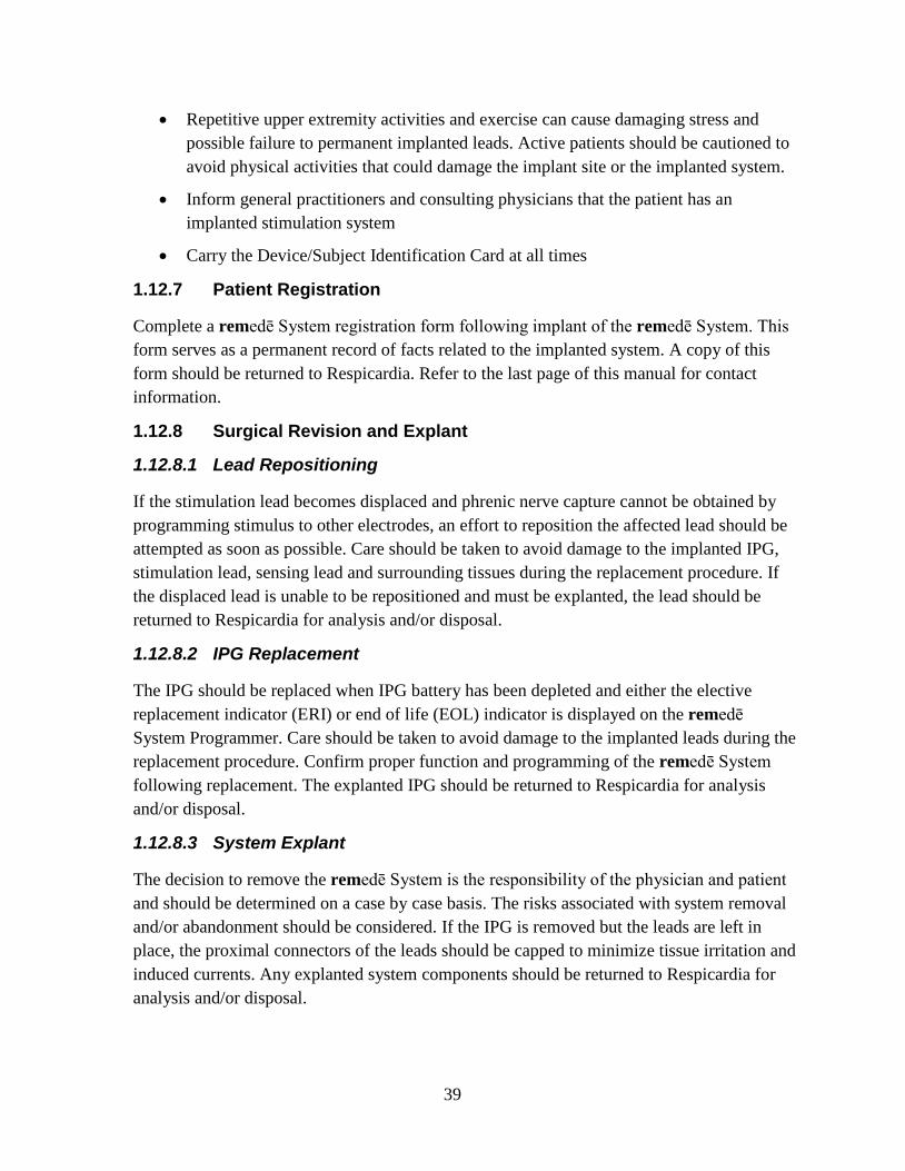
The System programmer tablet display is an interactive touch screen tablet controlled using the attached stylus. The external buttons and ports used by the remedē System are labeled along the border of the tablet display (On/Off, USB, and Power Plug). Other external buttons or controls on the tablet display are not used when programming the remedē System (see Figure 14).
40
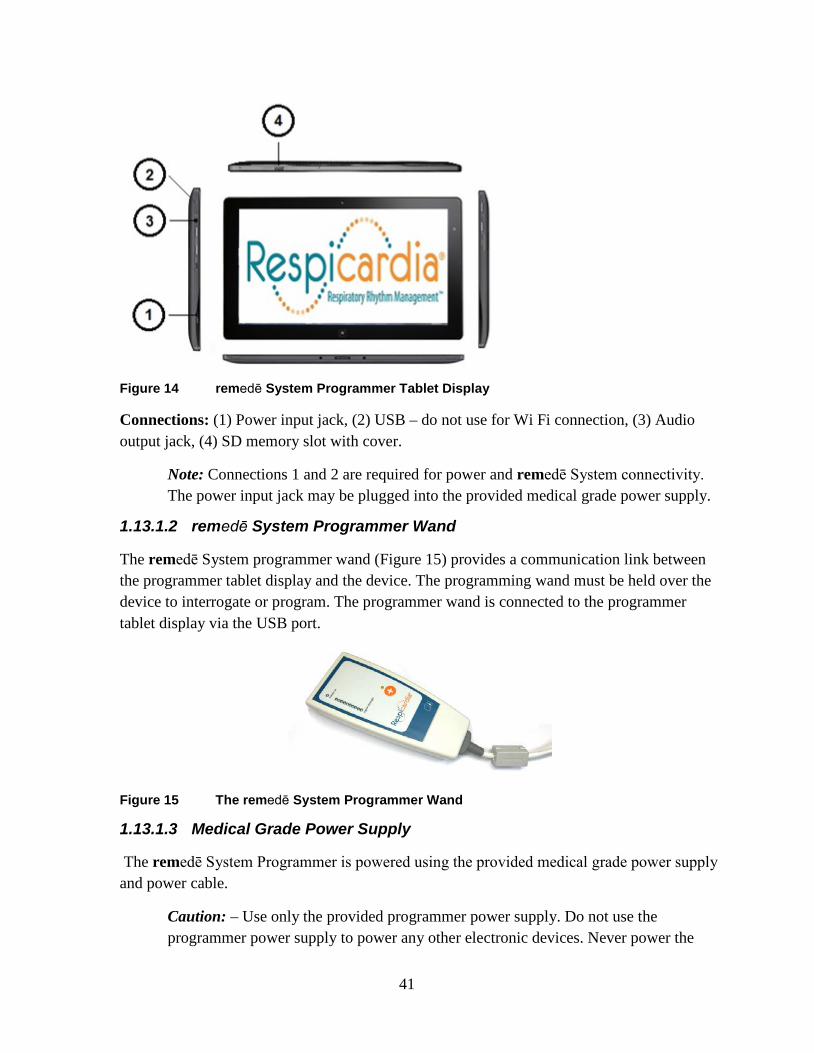
Figure 14 remedē System Programmer Tablet Display
Connections: (1) Power input jack, (2) USB – do not use for Wi Fi connection, (3) Audio output jack, (4) SD memory slot with cover.
Note: Connections 1 and 2 are required for power and remedē System connectivity. The power input jack may be plugged into the provided medical grade power supply.
1.13.1.2 remedē System Programmer Wand
The remedē System programmer wand (Figure 15) provides a communication link between the programmer tablet display and the device. The programming wand must be held over the device to interrogate or program. The programmer wand is connected to the programmer tablet display via the USB port.
Figure 15 The remedē System Programmer Wand
1.13.1.3 Medical Grade Power Supply
The remedē System Programmer is powered using the provided medical grade power supply and power cable.
Caution: – Use only the provided programmer power supply. Do not use the programmer power supply to power any other electronic devices. Never power the
41

remedē System programmer using an extension cord, power strip or other multiple outlet cable.
1.13.1.4 Connecting External Non-Respicardia Devices
Peripheral equipment connected to the programmer tablet display must be certified according to applicable International Electrotechnical Commission (IEC) standards for medical equipment. The system, formed by connecting peripheral equipment to the programmer, must comply with IEC 60601-1 for medical electrical systems. It is the responsibility of the user connecting the peripheral equipment to comply with IEC standards. It is the responsibility of the user to keep peripheral equipment that is certified to IEC 60950 at least two meters away from the patient. Contact the peripheral equipment manufacturer for information about IEC certification.
Caution: – To avoid a potential safety hazard, do not connect the remedē System Programmer to any non-certified outlet powered device (such as an external printer) during a patient session.
1.13.1.5 External USB/CAT5 Extension
An external USB/CAT5 extension kit may be used with the remedē System programmer to allow for extended System programmer use in a sleep lab control room during a sleep study (up to 150 ft. away from patient room). Use only an external USB/CAT5 extension kit that is compliant with IEC 60601-1 for medical electrical systems, compatible with USB 2.0 and provides power on the remote end of the extension.
1.13.2 Preparing for a Clinical Programming Session
1.13.2.1 Powering On the Programmer
The System programmer tablet display should be plugged in to an electrical outlet using the provided medical grade power supply. To power on the System programmer, press and hold the power button for at least 2 seconds until the blue LED next to the power button illuminates indicating power is on.
1.13.2.2 Starting the Software Application
When initially powered on, the System programmer will automatically launch the remedē System programmer software application. The user may also select the Respicardia remedē icon (Figure 16) from the desktop to start the remedē System programmer software application.
42
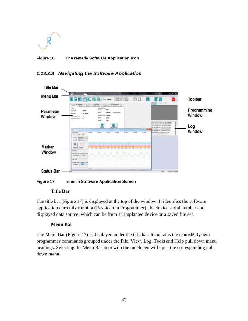
Figure 16 The remedē Software Application Icon
1.13.2.3 Navigating the Software Application
Figure 17 remedē Software Application Screen
Title Bar
The title bar (Figure 17) is displayed at the top of the window. It identifies the software application currently running (Respicardia Programmer), the device serial number and displayed data source, which can be from an implanted device or a saved file set.
Menu Bar
The Menu Bar (Figure 17) is displayed under the title bar. It contains the remedē System programmer commands grouped under the File, View, Log, Tools and Help pull down menu headings. Selecting the Menu Bar item with the touch pen will open the corresponding pull down menu.
43

Toolbar
The toolbar (Figure 17) is displayed under the Menu Bar and offers shortcuts to frequently used functions from the File, Log, and Tools pull down menus from the Menu Bar. The toolbar also provides direct access to the mode to allow the user to quickly program between off, therapy and monitor modes. Selecting a button on the toolbar with the stylus will initiate the chosen task. See Table 10 below for remedē Software application toolbar icons.
Table 10 remedē Software Application Toolbar Icons
New Device
Read Impedance
Open Saved Settings
Threshold Testing
Print Current Settings
Activate Therapy
Browse Current Log
Suspend Therapy
Marker Detail
Set IPG Time
Open Log File Activity & Pitch Report
Add Log Bookmark
Full Report
Marker Mode
Urgent Off
Parameter Window
The Parameter Window (Figure 17) contains all programmable parameters used to configure remedē System therapy. Once the remedē IPG is interrogated, the currently programmed settings are displayed in a tab format within the Parameter window. The parameters are grouped using a tab format with the following headings: Summary, Therapy, Stimulus, Weekly Titration, Nightly Titration, Sensors, Tools, Lab Parameters, Lab Status, and LOG Configuration. Selecting a tab heading will allow the user to view to the corresponding programmable parameters and their current values.
44

Programming Window
The Programming Window (Figure 17) allows a user to interrogate the device, directly execute a programming command and cancel pending programming changes that have not been executed or undo a previous programming command. A message field is located beneath the programming window buttons that details parameter value conflicts, if applicable.
Log Window
The Log Window (Figure 17) contains a message field detailing history log of all interactions between the device and programmer during a clinical programming session. Each log entry will contain the following format: description, status, date and time. The date and time correspond to the programmer clock. If the programmer clock is different from the clock maintained by the implanted device, a message will appear upon initial interrogation. If applicable, additional log entry information may be viewed by double tapping the specific log entry.
Marker Window
The Marker Window (Figure 17) may be used to graphically view live data collected by the device or to review previously collected waveforms and data. Two channels may be selected for viewing at a time.
Status Bar
The Status Bar (Figure 17) indicates any current communication event (for example, interrogation, programming and ready). The Status Bar may also be used to indicate the function of any buttons as the description will be displayed when the pointer is held over a button.
1.13.2.4 Positioning and Using the Programming Wand
During a clinical programming session, telemetry communication between the remedē System programmer and the remedē IPG requires the programming wand to be positioned over the patient’s implanted device. The programming wand must be in place over the implanted device for the duration of the programming session. Lifting or moving the programming wand out of telemetry range will interrupt or end any tests or operations in progress. Replacing the wand may allow the user to resume progress saving wave or log data, while other functions may need to be restarted.
The programming wand contains a number of LEDs to indicate proper position and function. A green power on LED indicates the programming wand is connected to the System programmer display and powered. A series of red, yellow, and green LEDs indicate telemetry signal strength with green indicating best communication, yellow indicating adequate
45

communication, and red or no LED illumination indicating poor or no communication. The programming wand should be repositioned in the case of red or no LED illumination.
Note: Best signal strength will be found when the distance between the Programming Wand and implanted device is less than 2.5 cm (1 inch).
1.13.2.4.1 Effect of Programming Wand on Concomitant Devices
The remedē System Programmer Wand does not contain a strong magnet. Placing the Programming Wand over a concomitantly implanted device is unlikely to have an effect on the operation and programming of the concomitant device.
1.13.2.5 Interrogating the remedē IPG
Position the Programming Wand directly over the implanted device and verify sufficient signal strength for proper communication. Select the interrogate button from the remedē Software Application (Figure 18) using the attached stylus or by selecting Interrogate under the File pull down menu on the Menu Bar. The interrogate button will illuminate in blue if no active programming session is in progress. After successfully completing the interrogation, the Summary Tab and associated parameters will appear displaying current device status and programmed settings.
Figure 18 Interrogate Button
46

1.13.2.5.1 Battery Status
The measured battery voltage will be displayed with one of the following battery status indicator messages:
Good The measured battery voltage level is above the elective replacement indicator level.
ERI The elective replacement indicator (ERI) is triggered after 3 consecutive battery measurements are less than 2.60V. The remedē IPG will continue to operate as programmed but replacement should be scheduled as soon as possible. Approximately 3.3 weeks of normal operation remain once ERI is triggered.
EOL The end of life indicator (EOL) is triggered when 3 consecutive battery measurements are less than 2.50V. Stimulation therapy is disabled when the battery reaches EOL and the remedē IPG should be replaced immediately.
1.13.2.6 Urgent Off Command Using the Programming Wand
The urgent off command is a safety feature that overrides all functions in effect and immediately disables stimulation therapy and programs the device to the off mode. The urgent off command may be initiated using the programming wand by selecting and holding the urgent off button for at least 2 seconds (Figure 19). An orange LED above the urgent off button will illuminate and flash 5 times to indicate successful programming. If not successful, the programming wand will automatically make one additional attempt to program the urgent off command. In this case the user should ensure the programming wand is positioned over the device with sufficient telemetry signal strength.
Figure 19 remedē System Programmer Wand Urgent Off Button
Once the remedē IPG has been interrogated, the user may also initiate the urgent off command by selecting Urgent Off from the Tools pull down menu on the Menu Bar or by selecting the urgent off icon from the toolbar (Figure 17).
47

Note: – The programming wand may be connected to any powered USB port to program the urgent off command and does not require the remedē software application.
1.13.2.7 Therapy Suspension Using a Magnet
The remedē System stimulation therapy can be suspended by placing a strong magnet over the implanted device (within 6 cm) in the event that the programming wand is unavailable. A magnetic sensor in the IPG can sense the presence of a strong, external magnetic field (most commonly generated by using a standard pacemaker donut magnet). The minimum magnetic field strength required to activate the magnet sensor is 25 Gauss as measured at the surface of the remedē System device. The magnet must be held in place for a minimum of 10 seconds to allow the remedē System to detect the magnetic field and confirm its presence. Once a magnetic field has been detected, the remedē System automatically suspends stimulation therapy. Once the magnetic field has been removed, stimulation therapy will resume at the next Scheduled Sleep Start Time (typically the next night when stimulation therapy is scheduled to start).
48
1.14 remedē® System Limited Warranty
A. LIMITED WARRANTY. RESPICARDIA, INC. (“SELLER”) PROVIDES TO THE ORIGINAL
PURCHASER OF THE PRODUCT (“BUYER”) THE FOLLOWING LIMITED WARRANTY FOR THE
REMEDĒ® SYSTEM, COMPRISED OF THE IMPLANTABLE NEUROSTIMULATOR (“STIMULATOR”), WIRES FOR SENSING AND STIMULATION (“LEADS”), A PORTABLE HANDHELD TABLET
(“TABLET”) A PATIENT WAND PROGRAMMING (”WAND”), AND THE PROPRIETARY
REMEDĒ® SYSTEM MOBILE APP WHICH IS INSTALLED ON THE TABLET (“APP”). EACH OF THE
STIMULATOR AND LEADS IS A “COMPONENT.” EACH OF THE TABLET AND WAND IS A “THIRD
PARTY PRODUCT”.
I. (A) EACH COMPONENT AND THIRD PARTY PRODUCT OF A SYSTEM WHEN DELIVERED TO
BUYER WILL BE NEW, OF HIGH QUALITY, AND FREE FROM MATERIAL DEFECTS AND CONSISTENT
WITH THE DOCUMENTATION PROVIDED; AND (B) THE APP WILL PERFORM SUBSTANTIALLY IN
ACCORDANCE WITH THE DOCUMENTATION ACCOMPANYING THE SYSTEM.
II. SHOULD THE APP FAIL TO PERFORM SUBSTANTIALLY IN ACCORDANCE WITH THE
DOCUMENTATION WITHIN ONE YEAR, SELLER’S SOLE OBLIGATION AND BUYER’S SOLE REMEDY
WILL BE FOR SELLER TO, AT ITS OPTION: (A) REPLACE OR REPAIR (INCLUDING AT SELLER’S
OPTION BY REMOTE UPDATE) THE NON-CONFORMING APP OR ANY NON-CONFORMING PORTIONS
THERETO WITH AN APP THAT CONFORMS TO THE DOCUMENTATION; OR (B) ISSUE A CREDIT TO
BUYER. FOR CLARITY, THE APP IS LICENSED, NOT SOLD, TO BUYER, AND SELLER RETAINS ALL
INTELLECTUAL PROPERTY RIGHTS IN AND TO THE APP.
III. SHOULD ANY COMPONENT FAIL TO FUNCTION WITHIN NORMAL USE DUE TO DEFECT IN
MATERIALS OR WORKMANSHIP WITHIN A PERIOD OF TWO (2) YEARS COMMENCING WITH THE
DELIVERY OF THE SUCH COMPONENT TO THE BUYER, SELLER’S SOLE OBLIGATION AND
BUYER’S SOLE REMEDY WILL BE FOR SELLER TO, AT ITS OPTION (A) REPAIR OR REPLACE THE
APPLICABLE COMPONENT; (B) PROVIDE A FUNCTIONALLY COMPARABLE REPLACEMENT
COMPONENT AT NO CHARGE; OR (C) ISSUE A CREDIT TO BUYER. SHOULD ANY THIRD PARTY
PRODUCT FAIL TO FUNCTION WITHIN NORMAL USE DUE TO DEFECT IN MATERIALS OR
WORKMANSHIP WITHIN A PERIOD OF ONE (1) YEAR COMMENCING WITH THE DELIVERY OF THE
SUCH THIRD PARTY PRODUCT TO THE BUYER, SELLER’S SOLE OBLIGATION AND BUYER’S SOLE
REMEDY WILL BE FOR SELLER TO, AT ITS OPTION (A) REPAIR OR REPLACE THE APPLICABLE
THIRD PARTY PRODUCT; (B) PROVIDE A FUNCTIONALLY COMPARABLE REPLACEMENT THIRD
PARTY PRODUCT AT NO CHARGE; OR (C) ISSUE A CREDIT TO BUYER.
IV. IF SELLER CHOOSES TO ISSUE A CREDIT TO BUYER FOR A COMPONENT OR THIRD PARTY
PRODUCT, THE CREDIT SHALL BE THE LESSER OF THE NET INVOICED PRICE OF THE ORIGINAL
COMPONENT OR THIRD PARTY PRODUCT, OR THE CURRENT FUNCTIONALLY COMPARABLE
COMPONENT OR THIRD PARTY PRODUCT OR REPLACEMENT COMPONENT OR THIRD PARTY
PRODUCT. IF SELLER CHOOSES TO ISSUE A CREDIT TO BUYER FOR THE APP, THE CREDIT SHALL
49

BE EQUAL TO THE FEES PAID FOR THE TABLET. FOR COMPONENTS OR THIRD PARTY PRODUCTS
THAT ARE USED WITH A SPECIFIC PATIENT, BUYER AGREES TO REFLECT THE CREDIT ON THE
APPLICABLE PATIENT’S BILL AND REPORT THE CREDIT TO THE APPLICABLE PAYOR.
V. IN ORDER TO QUALIFY FOR THE LIMITED WARRANTY SET FORTH HEREIN, THE
FOLLOWING CONDITIONS MUST BE MET: (A) THE COMPONENT OR THIRD PARTY PRODUCT MUST
NOT HAVE BEEN REPAIRED OR ALTERED OUTSIDE OF SELLER’S FACILITY OR IN ANY WAY WHICH
IN THE SOLE OPINION OF SELLER IMPACTS THE SYSTEM’S STABILITY AND RELIABILITY; (B) THE
COMPONENT OR THIRD PARTY PRODUCT MUST NOT HAVE BEEN SUBJECT TO ABUSE, LACK OF
PROPER MAINTENANCE, NEGLIGENCE, ACCIDENT, MOVEMENT, OR ADJUSTMENT OF EQUIPMENT
BY PERSONNEL NOT AUTHORIZED BY SELLER; (C) THE COMPONENT OR THIRD PARTY PRODUCT
MUST HAVE BEEN PUT INTO USE PRIOR TO ANY LABELED “USE BEFORE” DATE; (D) THE
COMPONENT OR THIRD PARTY PRODUCT MUST HAVE BEEN USED IN ACCORDANCE WITH
SELLER’S INSTRUCTIONS AND THE LABELING, AND MAY NOT HAVE BEEN USED FOR A PURPOSE
NOT INDICATED ON THE LABELING; AND (E) NEITHER THE APP NOR ANY OTHER SOFTWARE OR
FIRMWARE ON ANY COMPONENT OR THIRD PARTY PRODUCT MAY HAVE BEEN MODIFIED IN ANY
WAY BY ANY PERSON OTHER THAN SELLER. FURTHERMORE, DEFECTS ARISING IN WHOLE OR
PART AS A RESULT OF NORMAL WEAR AND USAGE, IMPROPER OR INADEQUATE MAINTENANCE, INTERRUPTIONS OR UNSUITABLE POWER OR COMMUNICATION SOURCES OR CONNECTIVITY, ENVIRONMENTAL CONDITIONS, ACCIDENT, MISUSE, ABUSE, IMPROPER INSTALLATION, MODIFICATION, REPAIR, STORAGE OR HANDLING, OR ANY OTHER CAUSE NOT THE FAULT OF
SELLER ARE NOT COVERED BY THIS LIMITED WARRANTY.
VI. THE LIMITED WARRANTY DOES NOT APPLY TO EXPIRATION OF COMPONENT OR THIRD
PARTY PRODUCTS PARTS WITH A LIMITED LIFETIME, SUCH AS THE BATTERY. SELLER HEREBY
ASSIGNS TO BUYER ANY AND ALL MANUFACTURERS’ OR SUPPLIERS’ WARRANTIES, GUARANTEES, REPRESENTATIONS, SERVICES AGREEMENTS AND INDEMNITIES, APPLICABLE TO
ANY THIRD PARTY HARDWARE OR SOFTWARE DELIVERED BY BUYER IN CONNECTION WITH THE
SYSTEM, TO THE EXTENT ASSIGNABLE BY SELLER.
B. CLAIMING THE LIMITED WARRANTY. PLEASE CONTACT SELLER’S SERVICE
DEPARTMENT OR THE AUTHORIZED REPRESENTATIVE BY MAIL OR PHONE PRIOR TO RETURNING
A COMPONENT OR THIRD PARTY PRODUCT FOR FURTHER INSTRUCTIONS. WHEN RETURNING A
COMPONENT OR THIRD PARTY PRODUCT, BUYER MUST INCLUDE A COMPLETE DESCRIPTION OF
THE ALLEGED COMPONENT OR THIRD PARTY PRODUCT FAILURE ACCOMPANIED BY A PROOF OF
PURCHASE ATTACHED TO THE COMPONENT OR THIRD PARTY PRODUCT. IN ORDER TO QUALIFY
FOR THE LIMITED WARRANTY SET FORTH HEREIN, BUYER MUST RETURN THE COMPONENT OR
THIRD PARTY PRODUCT TO SELLER WITHIN THIRTY (30) DAYS AFTER DISCOVERY OF DEFECT. SELLER WILL BEAR THE COSTS AND RISKS OF LOSS WITH ANY RETURN TRANSPORT TO SELLER. BUYER WILL BEAR THE COSTS AND RISKS OF THE RETURN TRANSPORT FOR REPLACEMENT OR
REPAIRED COMPONENTS OR THIRD PARTY PRODUCTS, PROVIDED HOWEVER, THAT BUYER
50

SHALL BE LIABLE TO SELLER FOR EXPENSES INCURRED IN CONNECTION WITH DIAGNOSING, REPAIRING AND/OR REPLACING ANY COMPONENT THIRD PARTY PRODUCT THAT WAS
RETURNED OUTSIDE OF WARRANTY.
C. DISCLAIMERS AND LIMITATION OF LIABILITY. THE LIMITED WARRANTY IS LIMITED TO
ITS EXPRESS TERMS. IN PARTICULAR:
I. EXCEPT AS EXPRESSLY PROVIDED BY THE LIMITED WARRANTY IN SECTION (A), SELLER MAKES NO OTHER REPRESENTATION OR WARRANTY, WITH RESPECT TO THE SYSTEM, ANY COMPONENT, ANY THIRD PARTY PRODUCT, OR THE APP, INCLUDING BUT NOT LIMITED TO, IMPLIED CONDITIONS OF FITNESS FOR A PARTICULAR PURPOSE, MERCHANTABILITY, NON-INFRINGEMENT, WARRANTIES ARISING FROM COURSE OF DEALING OR USAGE OF TRADE OR ANY
OTHER MATTER. SELLER MAKES NO REPRESENTATIONS WHATSOEVER, WHETHER EXPRESS OR
IMPLIED, TO ANY PERSON OTHER THAN THE BUYER. NO AGENT, EMPLOYEE OR REPRESENTATIVE
OF SELLER HAS ANY AUTHORITY TO BIND SELLER TO ANY AFFIRMATION, REPRESENTATION OR
WARRANTY EXCEPT AS STATED IN A WRITTEN DOCUMENT SIGNED BY AN AUTHORIZED OFFICER
OF SELLER. ALL WARNINGS CONTAINED IN THE LABELING FOR THE SYSTEM ARE AN INTEGRAL
PART OF THIS LIMITED WARRANTY.
II. SELLER IS NOT RESPONSIBLE FOR ANY INCIDENTAL, CONSEQUENTIAL DAMAGES
BASED ON ANY DEFECT, FAILURE OR MALFUNCTION OF THE SYSTEM, ANY COMPONENT, ANY
THIRD PARTY PRODUCT, OR THE APP, WHETHER THE CLAIM IS BASED ON WARRANTY, CONTRACT, TORT OR OTHERWISE. SELLER SHALL HAVE NO LIABILITY TO ANY PERSON FOR, AND
BUYER HEREBY EXPRESSLY WAIVES, ALL REMEDIES AND DAMAGES RELATING TO INDIRECT, INCIDENTAL, CONSEQUENTIAL, SPECIAL OR PUNITIVE DAMAGES OF ANY DESCRIPTION, WHETHER ARISING OUT OF WARRANTY OR OTHER CONTRACT, NEGLIGENCE OR OTHER TORT, OR
OTHERWISE, INCLUDING, WITHOUT LIMITATION, RESCISSION, DIFFERENCE IN VALUE DAMAGES, FORESEEABLE BUSINESS LOSSES, LOSS OF PROFITS AND RELIANCE DAMAGES. UNDER NO
CIRCUMSTANCES SHALL SELLER’S LIABILITY HEREUNDER FOR ANY CAUSE EXCEED THE
PURCHASE PRICE PAID BY BUYER FOR THE COMPONENT OR THIRD PARTY PRODUCT OUT OF
WHICH SUCH CLAIM OR ACTION AROSE. THE PARTIES EXPRESSLY AGREE THAT THE EXCLUSIONS
AND LIMITATIONS SET FORTH HEREIN ARE AGREED ALLOCATIONS OF RISK AND SHALL SURVIVE
THE DETERMINATION OF ANY COURT OF COMPETENT JURISDICTION THAT ANY REMEDY
PROVIDED HEREIN FAILS OF ITS ESSENTIAL PURPOSE.
III. THE EXCLUSIONS, DISCLAIMERS, AND LIMITATIONS SET FORTH HEREIN ARE NOT
INTENDED TO, AND SHALL NOT BE CONSTRUED AS TO, CONTRAVENE MANDATORY PROVISIONS
OF ANY APPLICABLE LAW OR REGULATION. IF ANY PART OF THIS SECTION IS HELD TO BE
ILLEGAL OR UNENFORCEABLE BY A COURT OF COMPETENT JURISDICTION, THE PART SHALL BE
MODIFIED SO AS TO BE ENFORCEABLE TO THE MAXIMUM EXTENT POSSIBLE. IF THE PART
CANNOT BE MODIFIED, THEN THAT PART MAY BE SEVERED AND THE OTHER PARTS OF THE
LIMITED WARRANTY SHALL REMAIN IN FULL FORCE AND EFFECT. THIS LIMITED
51

WARRANTY IS EXPRESSED FOR THE SOLE BENEFIT OF THE ORIGINAL USER WHO PURCHASES OR
RECEIVES THE SYSTEM, COMPONENT, APP, OR THIRD PARTY PRODUCT, AND IS NOT
TRANSFERABLE.
52
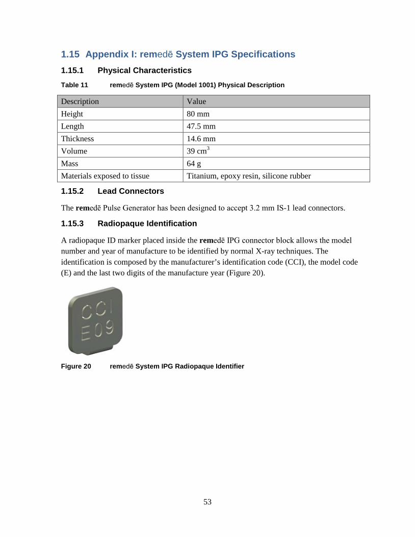
1.15 Appendix I: remedē System IPG Specifications 1.15.1 Physical Characteristics Table 11 remedē System IPG (Model 1001) Physical Description
Description Value Height 80 mm Length 47.5 mm Thickness 14.6 mm Volume 39 cm3 Mass 64 g Materials exposed to tissue Titanium, epoxy resin, silicone rubber
1.15.2 Lead Connectors
The remedē Pulse Generator has been designed to accept 3.2 mm IS-1 lead connectors.
1.15.3 Radiopaque Identification
A radiopaque ID marker placed inside the remedē IPG connector block allows the model number and year of manufacture to be identified by normal X-ray techniques. The identification is composed by the manufacturer’s identification code (CCI), the model code (E) and the last two digits of the manufacture year (Figure 20).
Figure 20 remedē System IPG Radiopaque Identifier
53
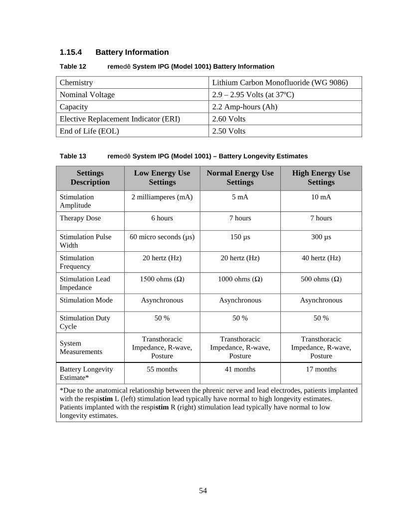
1.15.4 Battery Information Table 12 remedē System IPG (Model 1001) Battery Information
Chemistry Lithium Carbon Monofluoride (WG 9086) Nominal Voltage 2.9 – 2.95 Volts (at 37ºC) Capacity 2.2 Amp-hours (Ah) Elective Replacement Indicator (ERI) 2.60 Volts End of Life (EOL) 2.50 Volts
Table 13 remedē System IPG (Model 1001) – Battery Longevity Estimates
Settings Description
Low Energy Use Settings
Normal Energy Use Settings
High Energy Use Settings
Stimulation Amplitude
2 milliamperes (mA) 5 mA 10 mA
Therapy Dose 6 hours 7 hours 7 hours
Stimulation Pulse Width
60 micro seconds (µs) 150 µs 300 µs
Stimulation Frequency
20 hertz (Hz) 20 hertz (Hz) 40 hertz (Hz)
Stimulation Lead Impedance
1500 ohms (Ω) 1000 ohms (Ω) 500 ohms (Ω)
Stimulation Mode Asynchronous Asynchronous Asynchronous
Stimulation Duty Cycle
50 % 50 % 50 %
System Measurements
Transthoracic Impedance, R-wave,
Posture
Transthoracic Impedance, R-wave,
Posture
Transthoracic Impedance, R-wave,
Posture
Battery Longevity Estimate*
55 months 41 months 17 months
*Due to the anatomical relationship between the phrenic nerve and lead electrodes, patients implanted with the respistim L (left) stimulation lead typically have normal to high longevity estimates. Patients implanted with the respistim R (right) stimulation lead typically have normal to low longevity estimates.
54

1.15.5 Programmable Settings Table 14 remedē System IPG (Model 1001) Programmable Settings
Parameter Factory Value
Programmable Values
Increment
Therapy Mode Off Off, Therapy, Monitor Algorithm Mode Asynchronous Asynchronous,
Synchronous
Asynchronous Respiratory Rate
16 breaths per minute (bpm)
10 – 30 bpm 1 bpm
Stay in Monitor Off On, Off Asynchronous I:E Ratio 1.0 0.5 – 2.0 0.1 Synchronous Backup Ventilation
16 bpm 10 – 30 bpm 1 bpm
Synchronous Backup Only Off On, Off Synchronous Stimulation Duration
2.0 seconds (sec)
0.5 – 30.0 0.1 sec
Synchronous Delay 0.5 sec 0.1 – 4.0 sec 0.1 sec Synchronous Blanking Period
0.4 sec 0.1 – 20.0 sec 0.1 sec
Scheduled Sleep Start (all days)
22:00 (HH:MM)
00:00 – 23:30 (HH:MM) 30 min
Scheduled Sleep Stop (all days)
06:00 (HH:MM)
00:00 – 23:30 (HH:MM) 30 min
Maximum Dose 8 hours (hrs) 00:30 – 12:00 30 min Lack of Respiration Period 8.0 sec 0.5 – 30.0 sec 0.5 sec
Stimulation
Amplitudes (Supine, Left, Right, Prone)
0.1 mA 0.0 – 10.0 mA 0.1 mA
Maximum Amplitudes (Supine, Left, Right, Prone)
0.1 mA 0.1 – 10.0 mA 0.1 mA
Pulse Width 150 μs 60 – 300 μs 30 μs Frequency 20 Hz 10, 20 40 Hz Anode (+) Electrode 2 Electrode 1, 2, 3, 4, 5, 6 Cathode (-) Electrode 1 Electrode 1, 2, 3, 4, 6,
Can
55
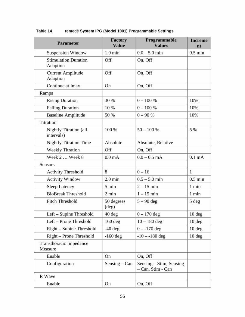
Table 14 remedē System IPG (Model 1001) Programmable Settings
Parameter Factory Value
Programmable Values
Increment
Suspension Window 1.0 min 0.0 – 5.0 min 0.5 min Stimulation Duration Adaption
Off On, Off
Current Amplitude Adaption
Off On, Off
Continue at Imax On On, Off Ramps
Rising Duration 30 % 0 – 100 % 10% Falling Duration 10 % 0 – 100 % 10% Baseline Amplitude 50 % 0 – 90 % 10%
Titration Nightly Titration (all intervals)
100 % 50 – 100 % 5 %
Nightly Titration Time Absolute Absolute, Relative Weekly Titration Off On, Off Week 2 … Week 8 0.0 mA 0.0 – 0.5 mA 0.1 mA
Sensors Activity Threshold 8 0 – 16 1 Activity Window 2.0 min 0.5 – 5.0 min 0.5 min Sleep Latency 5 min 2 – 15 min 1 min BioBreak Threshold 2 min 1 – 15 min 1 min Pitch Threshold 50 degrees
(deg) 5 – 90 deg 5 deg
Left – Supine Threshold 40 deg 0 – 170 deg 10 deg Left – Prone Threshold 160 deg 10 – 180 deg 10 deg Right – Supine Threshold -40 deg 0 – -170 deg 10 deg Right – Prone Threshold -160 deg -10 – -180 deg 10 deg
Transthoracic Impedance Measure
Enable On On, Off Configuration Sensing – Can Sensing – Stim, Sensing
– Can, Stim - Can
R Wave Enable On On, Off
56

Table 14 remedē System IPG (Model 1001) Programmable Settings
Parameter Factory Value
Programmable Values
Increment
Configuration Can & Distal Proximal & Distal, Can & Proximal, Can & Distal
Sensitivity 1.0 millivolt (mV)
0.5 – 5.0 mV 0.5 mV
Refractory 200 millisecond (ms)
200 – 500 ms 50 ms
dEMG Enable Off On, Off Gain Low Low, Medium, High Configuration Can & Distal Proximal & Distal, Can
& Proximal, Can & Distal
57

1.16 Appendix II: respistim L, LQ, and LQS Stimulation Lead Specifications
1.16.1 Physical Characteristics
Recommended Guiding Catheter 6 French minimum Electrodes
• Material Platinum/Iridium • Electrode Surface Area 12 millimeters2 • Coating None • Steroid None
Lead Diameter • Body 3.6 French • Electrodes 3.9 French • Inside Diameter 0.020 inch • Insulation Material Polyurethane 90A
Terminal • Compatibility IS-1 • Material 316L Stainless Steel
Conductors • Type Co-axial design, hexafilar coil with coated wire
Table 15 respistim L, LQ, and LQS Lead Model Descriptions
respistim L Model Length (centimeters) 2001 35 2002 45 2003 55 2004 70
respistim LQ Model Length (centimeters) 5045 45 5055 55 5065 65 5085 85
respistim LQS Model Length (centimeters) 4045 45 4055 55 4065 65 4085 85
58

1.17 Appendix III: respistim R Lead Specifications 1.17.1 Physical Characteristics
Recommended Introducer 8 French Electrodes
• Material Platinum/Iridium
• Electrode Surface Area 29 millimeters2 • Coating None
• Steroid None Lead Diameter
• Proximal Body 4.8 French
• Distal Body 7.0 French • Inside Diameter 0.020 inch • Insulation Material Polyurethane 90A
Terminal • Compatibility IS-1 • Material 316L Stainless Steel
Conductors • Type Co-axial design, hexafilar coil with coated wire
Table 16 respistim R Model Descriptions
Model Length
(centimeters) Distal Helical Spring Length (millimeters)
Distal Helical Spring Diameter (millimeters)
3101 60 25 20 3102 60 25 24 3103 60 35 20 3104 60 35 24 3105 60 45 20 3106 60 45 24 3201 80 25 20 3202 80 25 24 3203 80 35 20 3204 80 35 24 3205 80 45 20 3206 80 45 24
59

1.18 Appendix IV: Additional Programmer and eIPG Details
The programmer display is a commercially available tablet computer certified for use in a clinical environment as the remedē System programmer. The programmer does not contain any user serviceable parts.
1.18.1 Power Supply
The remedē System programmer is provided with a medical grade power supply and power cable that fulfills the standard IEC 60601-1:2012. The power supply is rated as follows: 100-240 VAC, 2.0-1.0A, 50-60Hz.
Use only the power supply and power cable provided by Respicardia. The power supply provides electrical isolation to the patient and operator from electrical power mains.
1.18.2 Routine Cleaning
Always turn the remedē System programmer OFF prior to cleaning.
When necessary, it is recommended that a soft cloth dampened with distilled water or isopropyl alcohol be used to wipe the exterior case of the programming wand. Do not use solvents or cleaning cloths containing chemical cleaning agents.
1.18.3 Cybersecurity Considerations
Do not attempt to install software on the remedē System programmer. Software installation may introduce viruses/ malware into the system and corrupt the system configuration. This may result in a malfunction or the inability to use the remedē System programmer.
The remedē System programmer wireless network (Wi-Fi) access has been disabled to enhance system cybersecurity robustness. Do not remove the remedē System programmer Micro SD port cover at any time.
Do not attempt to use Wi-Fi via a USB connection on the remedē System programmer. The remedē System programmer is not intended for use with any Wi-Fi connection.
1.18.4 eIPG Cable
The Respicardia eIPG is used with a sterile cable having two covered alligator clips on one end and two 2mm male shrouded connector pins on the opposite end. The cable should have a length of 2-3 meters.
60

1.19 Appendix V: remedē System Programmer Electromagnetic Interference Information
The remedē System may be subject to interference from other electrical equipment being operated in the near vicinity. Specifically, portable and mobile radiofrequency (RF) equipment can interfere with the normal operation of the programming system. This shall be taken into account in any situation where the equipment is not operating as expected. The remedē System Programmer may be interfered by other equipment, even if that equipment complies with CISPR emission limits.
Table 17 Electromagnetic Emissions Guidance Declaration
Guidance and manufacturer’s declaration – Electromagnetic Emissions
The remedē System Programmer is intended for use in the electromagnetic environment specified below. Emissions Test Compliance Electromagnetic Environment – Guidance
RF emissions CISPR 11
Group 1 The remedē System Programmer uses RF energy only for its internal function. Therefore, its RF emissions are very low and are not likely to cause interference in nearby electronic equipment.
RF emissions CISPR 11
Class B
The remedē System is suitable for use in all establishments, including domestic establishments and those directly connected to the public low voltage power supply network that supplies buildings used for domestic purposes. Harmonic
Emissions IEC 61000-3-2
Class A
Voltage fluctuations/flicker emissions IEC 61000-3-3
Complies
61
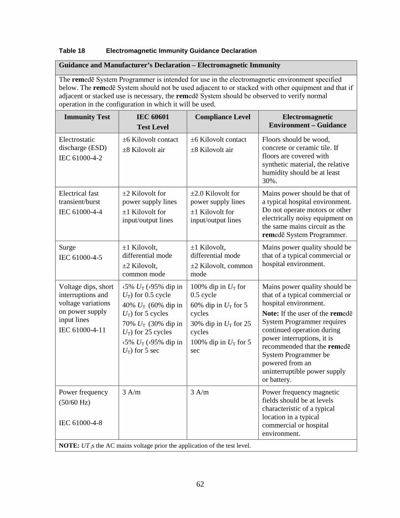
Table 18 Electromagnetic Immunity Guidance Declaration
Guidance and Manufacturer’s Declaration – Electromagnetic Immunity
The remedē System Programmer is intended for use in the electromagnetic environment specified below. The remedē System should not be used adjacent to or stacked with other equipment and that if adjacent or stacked use is necessary, the remedē System should be observed to verify normal operation in the configuration in which it will be used.
Immunity Test IEC 60601 Test Level
Compliance Level Electromagnetic Environment – Guidance
Electrostatic discharge (ESD) IEC 61000-4-2
±6 Kilovolt contact ±8 Kilovolt air
±6 Kilovolt contact ±8 Kilovolt air
Floors should be wood, concrete or ceramic tile. If floors are covered with synthetic material, the relative humidity should be at least 30%.
Electrical fast transient/burst IEC 61000-4-4
±2 Kilovolt for power supply lines ±1 Kilovolt for input/output lines
±2.0 Kilovolt for power supply lines ±1 Kilovolt for input/output lines
Mains power should be that of a typical hospital environment. Do not operate motors or other electrically noisy equipment on the same mains circuit as the remedē System Programmer.
Surge IEC 61000-4-5
±1 Kilovolt, differential mode ±2 Kilovolt, common mode
±1 Kilovolt, differential mode ±2 Kilovolt, common mode
Mains power quality should be that of a typical commercial or hospital environment.
Voltage dips, short interruptions and voltage variations on power supply input lines IEC 61000-4-11
‹5% UT (›95% dip in UT) for 0.5 cycle 40% UT (60% dip in UT) for 5 cycles 70% UT (30% dip in UT) for 25 cycles ‹5% UT (›95% dip in UT) for 5 sec
100% dip in UT for 0.5 cycle 60% dip in UT for 5 cycles 30% dip in UT for 25 cycles 100% dip in UT for 5 sec
Mains power quality should be that of a typical commercial or hospital environment. Note: If the user of the remedē System Programmer requires continued operation during power interruptions, it is recommended that the remedē System Programmer be powered from an uninterruptible power supply or battery.
Power frequency (50/60 Hz) IEC 61000-4-8
3 A/m 3 A/m Power frequency magnetic fields should be at levels characteristic of a typical location in a typical commercial or hospital environment.
NOTE: UT is the AC mains voltage prior the application of the test level.
62
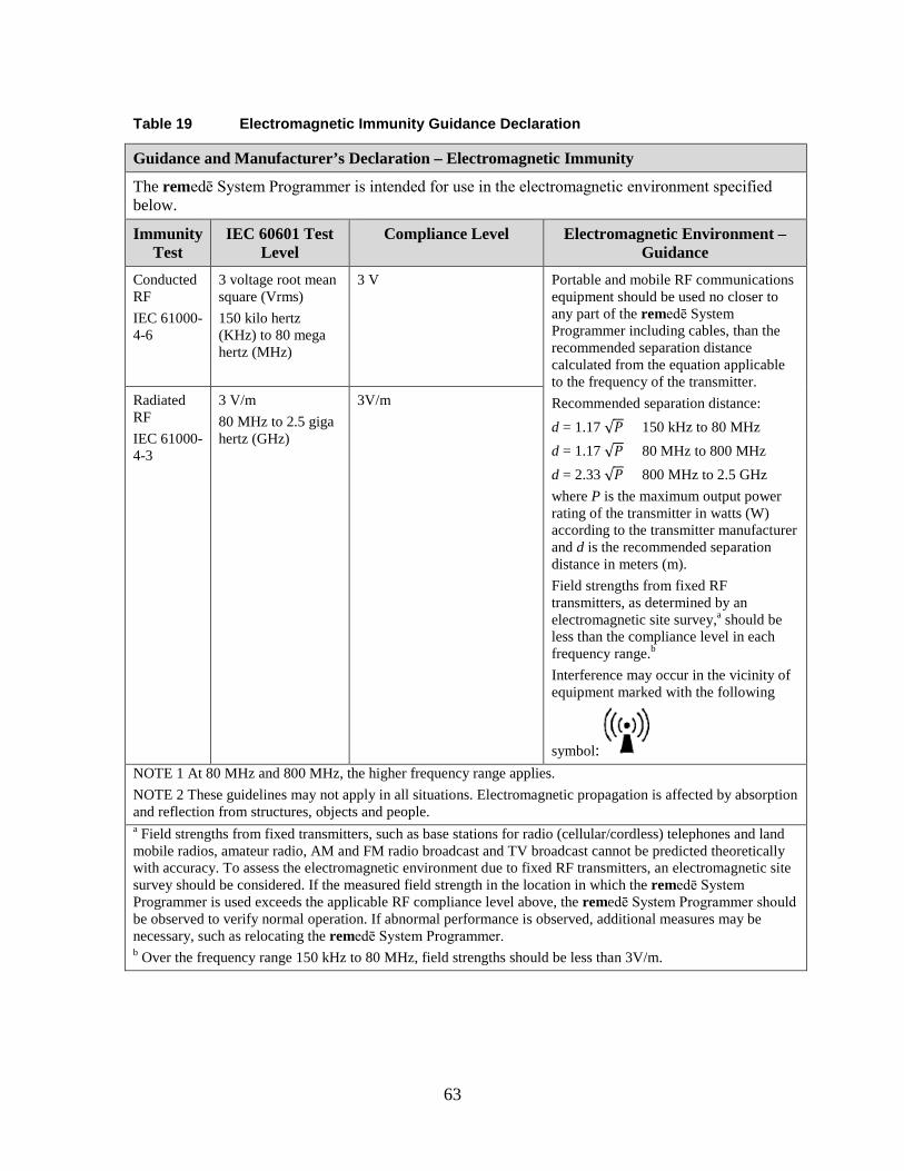
Table 19 Electromagnetic Immunity Guidance Declaration
Guidance and Manufacturer’s Declaration – Electromagnetic Immunity
The remedē System Programmer is intended for use in the electromagnetic environment specified below.
Immunity Test
IEC 60601 Test Level
Compliance Level Electromagnetic Environment – Guidance
Conducted RF IEC 61000-4-6
3 voltage root mean square (Vrms) 150 kilo hertz (KHz) to 80 mega hertz (MHz)
3 V
Portable and mobile RF communications equipment should be used no closer to any part of the remedē System Programmer including cables, than the recommended separation distance calculated from the equation applicable to the frequency of the transmitter. Recommended separation distance: d = 1.17 √𝑃𝑃 150 kHz to 80 MHz d = 1.17 √𝑃𝑃 80 MHz to 800 MHz d = 2.33 √𝑃𝑃 800 MHz to 2.5 GHz where P is the maximum output power rating of the transmitter in watts (W) according to the transmitter manufacturer and d is the recommended separation distance in meters (m). Field strengths from fixed RF transmitters, as determined by an electromagnetic site survey,a should be less than the compliance level in each frequency range.b
Interference may occur in the vicinity of equipment marked with the following
symbol:
Radiated RF IEC 61000-4-3
3 V/m 80 MHz to 2.5 giga hertz (GHz)
3V/m
NOTE 1 At 80 MHz and 800 MHz, the higher frequency range applies. NOTE 2 These guidelines may not apply in all situations. Electromagnetic propagation is affected by absorption and reflection from structures, objects and people. a Field strengths from fixed transmitters, such as base stations for radio (cellular/cordless) telephones and land mobile radios, amateur radio, AM and FM radio broadcast and TV broadcast cannot be predicted theoretically with accuracy. To assess the electromagnetic environment due to fixed RF transmitters, an electromagnetic site survey should be considered. If the measured field strength in the location in which the remedē System Programmer is used exceeds the applicable RF compliance level above, the remedē System Programmer should be observed to verify normal operation. If abnormal performance is observed, additional measures may be necessary, such as relocating the remedē System Programmer. b Over the frequency range 150 kHz to 80 MHz, field strengths should be less than 3V/m.
63

Table 20 Recommended Separation Distances Between Portable and Mobile RF Communications Equipment
Recommended separation distances between portable and mobile RF communications equipment and the remedē System Programmer
The remedē System Programmer is intended for use in an electromagnetic environment in which radiated RF disturbances are controlled. The customer or user of the remedē System Programmer can help prevent electromagnetic interference by maintaining a minimum distance between portable and mobile RF communications equipment (transmitters) and the remedē System Programmer as recommended below, according to the maximum output power of the communications equipment.
Rated maximum output power of transmitter W
Separation distance according to frequency of transmitter M
150 kHz to 80 MHz d = 1.17 √𝑃𝑃
80 MHz to 800 MHz d = 1.17 √𝑃𝑃
800 MHz to 2.5 GHz d = 2.33 √𝑃𝑃
0.01 0.12 0.40 1.47
0.1 0.37 0.71 1.97
1 1.17 1.27 2.62
10 3.7 2.25 3.50
100 11.7 4.0 4.66
For transmitters rated at a maximum output power not listed above, the recommended separation distance d in meters (m) can be estimated by using the equation applicable to the frequency of the transmitter, where P is the maximum output power rating of the transmitter in watts (W) according to the transmitter manufacturer. NOTE 1 At 80 MHz and 800 MHz, the higher frequency range applies. NOTE 2 These guidelines may not apply in all situations. Electromagnetic propagation is affected by absorption and reflection from structures, objects and people.
64

1.20 Appendix VI: remedē System Programmer Communications & Telemetry
1.20.1 Telemetry Data
Telemetry communication through magnetic induction with the programmer provides the means to view and set system parameters and collect device data obtaining the following information:
• All programmable parameters • Patient information (IPG model/serial number, Lead model/serial number, Patient ID,
Physician contact information, implant date, patient time zone) • Battery voltage and condition indicator (Good, Early Replacement Indicator [ERI],
and End of Life [EOL]) • Statistics that include sensing and stimulation events • Stimulation lead impedance as well as historical record of these values
The remedē System Programmer communicates with the remedē IPG using a proprietary telemetry communication protocol.
Table 21 Telemetry Transmission Characteristics
remedē System Programmer Transmission Characteristics to Implanted Device
ASK: “0” = tone absence, “1” = tone presence, Bit length = 0.305 ms 16-20 kHz carrier Range: ≤ 6 cm Power: 0.56Wpeak, 0.27Waverage
1.20.2 Troubleshooting
Telemetry communication through magnetic induction with the programmer may encounter situations that require user intervention. The following are potential communication issues that may occur and the action that should be taken by the user. 1.20.2.1 Loss of Communication with Programmer Wand
If a loss of communication between the Programmer Display and the Programmer Wand has occurred, a message indicating loss of interface connection will appear on the Programmer Display.
65

Action: Unplug the USB cable connecting the Programmer Wand to the Programmer Display and wait at least 5 seconds before reconnection.
• Additional Information: A loss of communication may be incurred by unplugging the USB cable or as a safety effect in the presence of excessive electromagnetic interference (EMI), an excessive electrostatic discharge (ESD), or other high energy burst (e.g. external defibrillation).
1.20.2.2 Loss of Marker Mode or Other Telemetry Error Messages
If a loss of communication between the Programmer Wand and the implanted device has occurred, a message indicating loss of telemetry connection will appear on the Programmer Display.
Action: Confirm the Programming Wand is within the secure communication zone and attempt telemetry operation again.
• Additional Information: A loss of communication may incur due to the Programming Wand not being within the secure communication zone or a result of the presence of excessive electromagnetic interference (EMI), excessive electrostatic discharge (ESD), or other high energy burst (e.g. external defibrillation).
1.20.2.3 Loss of Programmer Operating System Functions
If the Programmer Display experiences a functional error as related to the PC’s Operating System the Windows system may report an error or cause the screen to become blue with reported error condition, or become non-responsive to any attempted input.
Action: The Programmer Display may be reset by pushing the recessed button on the backside of the PC tablet. Once the system returns to the Windows desktop, launch the remedē System Programmer Software application and proceed with the programming session.
• Additional Information: A system error, while rare, may occur with the Windows Operating System of the remedē System Programmer Display due to any number of reasons. If the error is repeated the user should contact Respicardia.
• Note: If any unforeseen problem arises that renders the programmer unable to perform normally, the user should contact Respicardia.
66

1.21 Appendix VII: Service and Disposal Information 1.21.1 Service
All servicing of the remedē System Programmer components shall be performed by Respicardia, Inc. personnel. For Customer service, contact the address below:
Respicardia, Inc. 12400 Whitewater Drive, Suite 150 Minnetonka, MN 55343 USA Phone: (952) 540-4470 Fax: (952) 540-4485 E-mail: [email protected] http://www.respicardia.com
1.21.2 Disposal
The remedē IPG and leads that have been exposed to blood and/or body fluids shall be considered to be a potential biohazard and disposed of according to local environmental regulations. The remedē System Programmer, programming wand, and external IPG shall be considered as electronic waste and disposed of according to local environmental regulations.
67

Respicardia, Inc. 12400 Whitewater Drive, Suite 150 Minnetonka, MN 55343 USA Phone: (952) 540-4470 Fax: (952) 540-4485 E-mail: [email protected] http://www.respicardia.com
The information in this document can be changed without previous warning. No part of this manual may be reproduced or transmitted in any way or by any means, either electronic or mechanical, for any purpose without explicit written allowance by Respicardia, Inc.
Revision 1
68