the research and design of a new abs system for automotive by using the gmr sensor
TRANSCRIPT
The Research and Design of a
New ABS System for
Automotive by using the GMR
Sensor
MSc by research Project
Electronics Department
University of York
Chenhui Bao
Supervisor: Prof Yongbing XU
Feb 2012
Abstract
This dissertation explores the potential improvement of ABS
design through the replacement of widely used Hall-effect
sensor with the more sensitive GMR sensor technology and
the replacement of wired with wireless transmission of
information. The dissertation contributes an overview of
main existing types of sensors that can be used for ABS
design, describing the underlying technology of each as well
as their main strengths and weaknesses. In addition, the
dissertation proposes a GMR ABS design and reports on the
results obtained during its validation through simulation and
subsequent evaluation of a laboratory prototype built
according to the design.
The contribution of this dissertation is threefold: the
overview of existing sensor technology offers a
comprehensive big picture of the field and serves to identify
the most promising technology that can improve the
performance of modern ABS; the design validated,
implemented and evaluated provides conclusive proof of the
feasibility of using GMR sensors and wireless transmission,
as well as promising results regarding the potential
performance gain; a comparison of the observed
characteristics of the GMR sensor's performance during
evaluation with known characteristics of the more usual
Hall-effect sensor gives further evidence as to the potential
gains that can be expected from a replacement of Hall-effect
sensors with GMR sensors.
The results of this work represent initial proofs of concept

and of potential gains, opening thus a multitude of directions
for future research, as detailed in the last chapter of this
dissertation.
Table of Contents
Table of Contents……………………………………………..
List of illustration…………………………………………….
Acknowledgement……………………………………..........9
Chapter 1: Introduction…………………………………10
1.1 Aims and objectives……………………………………14
1.2 Methodology…………………………………………..15
1.3 Structure of the dissertation……………………………16
Chapter 2: Brake systems………………………………..19
2.1 Evolution of brake systems technology and design…...20
2.2 ABS functioning……………………………………….24
2.3 Most common types of sensors………………………..27
2.3.1 Variable reluctance sensors…………………………..27
2.3.2 Wiegand effect sensors………………………………28
2.3.3 Hall effect sensors…………………………………...29
2.3.4 Magnetoresistor sensors……………………………..30
2.3.5 AMR sensors………………………………………...31
2.3.6 GMR sensors………………………………………...31
Chapter 3: Proposed GMR ABS system………………...35
3.1 Aim and motivation……………………………………35
3.2 General design and components……………………….37
3.2.1 GMR Sensor…………………………………………39
3.2.2 Wireless Transmission System………………………43
3.2.3 Controller (Control Unit)…………………………….51
3.3 Design valid……………………………………………55
3.3.1 Simulation environment……………………………..56
3.3.2 Simulation of MCU signal process circuit…………..58
3.3.3 Simulation of the solenoid valve control circuit…….62
3.3.4 Simulation of the pump motor control circuit……….64
3.4 Design evaluation……………………………………...65
3.4.1 PCB board implementation………………………….66

3.4.2 Experimental setup…………………………………..70
3.4.3 Test results…………………………………………...75
3.4.4 Discussion of results………………………………81
Chapter 4: Comparison of GMR ABS with existing Hall
ABS………………………………………………………..84
Chapter 5: Limitations……………………………….......87
Chapter 6: Conclusions and future work……………….91
Bibliography………………………………………………99
Appendix………………………………………………106
Appendix I…………………………………………106
Appendix II………………………………………...107
Appendix III………………………………………108
Appendix IV……………………………………….109
Appendix V………………………………………..110
Appendix VI……………………………………….111
Appendix VII………………………………………112
Appendix VIII……………………………………...113
Appendix IX……………………………………….115
Appendix X………………………………………..116
List of Illustration
Figure 1: Depiction of a hydraulic brake system………….22
Figure 2: Overall diagram of an ABS system in a car……24
Table 1: Main advantages of GMR compared to the
corresponding characteristics of Hall and AMR
sensors……………………………………………33
Figure 3: The general, standard workflow of a braking
system, preserved as such in the proposed
design……………………………………………..37
Figure 4: High-level overview of proposed GMR ABS
system design, showing the three main components
that are altered with respect to a standard design..39
Figure 5: Block diagram of the AKL series sensor parts......40
Figure 6: Block diagram of wireless transmitter………......46
Figure7: Block diagram of wireless receiver ER400RS-02.46
Figure 8: Processing circuit for signal comparison………49
Figure 9: Partial circuit diagram showing the connection of
the wireless transmitter to the MCU AT89C52 that
transforms the signal into the TXD………….…...50
Figure 10: Partial circuit diagram, showing the wireless
transmitter and wireless receiver…………………51
Table 2: The internal states of the four high-speed input
channels in the MCU 80C196KC and their
respective meaning……………………………….52
Figure 11: Flow chart showing the overall workflow
implemented for the MCU 80C196KC…………55
Figure 12: Diagram of MCU signal process circuit……….59
Figure 13: Simulation settings and results for the MCU
signal circuit……………………………………61
Figure 14: The control circuit of the solenoid valve………63
Figure 15: Simulation setup and results for the solenoid
valve circuit………………………………………63

Figure 16: Simulation setup and results for the pump motor
circuit……………………………………………..65
Figure 17: Block Diagram of Overall Circuit……………..66
Figure 18: The signal acquisition part of the GMR ABS
prototype………………………………………….68
Figure 19: The main signal processing part of the GMR
ABS………………………………………………68
Figure 20: The solenoid valve control part of the GMR ABS
prototype………………………………………….69
Figure 21: The pump motor control part of the GMR ABS
prototype………………………………………….70
Figure 22: The gearwheel used for testing the proposed GMR
ABS………………………………………………72
Figure 1: Experimental setup showing the gear wheel and the
attachment of the sensor that is connected further
to the circuit for initial processing and wireless
t r a n s m i s s i o n … … … … … … … … … … . . 7 5
Table 3: Results of Test1, measuring the sensor signal output
at various speeds and constant air gap……………76
Figure 24: Oscilloscope reading for Test1, at a speed of
approximately 10mph and an air gap of 3mm……76
Figure 25: Drawn sine wave corresponding to output signal
obtained at 10mph and 3mm air gap……………77
Figure 26: Oscilloscope reading for Test1, at a speed of
approximately 60mph and an air gap of 3mm……77
Figure 27: Drawn sine wave corresponding to output signal
obtained at 60mph and 3mm air gap……………..78
Table 4: Results of Test2, measuring the sensor signal output
at constant speed and different air gaps…………..79
Figure 28: Oscilloscope reading for Test2, at a speed of
approximately 10mph and an air gap of 4.5mm….79
Figure 29: Oscilloscope reading for Test2, at a speed of
approximately 10mph and an air gap of 5.5mm….80

Figure 30: Results of Test2 showing how the sensor’s output
signal amplitude decreases when the air gap in
increased, although the speed is maintained
constant…………………………………………...80

9
Acknowledgement
I would like to acknowledge the help I received from
a large number of people during this project and to
express my heartfelt gratitude to all of them – without
them, I would not have been able to complete this
dissertation and to learn so much in such a short time.
I am especially grateful to the following people that
were particularly helpful throughout the project:
The technicians working in the 4th
floor lab were of
great help to me as they answered patiently my many
questions and gave me in return a lot of useful
advice.
Finally, my housemates provided me with much
needed encouragement throughout the hard times and
they selfishly took on some of my housework duties
to allow me to devote more time to my project so that
I can finish it on time. Their constant encouragement,
support and understanding truly enabled me to
complete this project.

10
Chapter 1 Introduction
Cars and transportation are an important part of
modern life. As the number of cars on the road
increases, traffic conditions become more and more
complex (Wilschut and de Waard, 2011). In turn, this
leads to an increased number of accidents, with an
estimated number of 50,000 people killed in traffic
every year in Europe alone (Brookhuis and de Waard,
2007). Most often, the causes of accidents are human
errors that are increasingly due to the complexity of
traffic conditions and modern driving (Smiley and
Brookhuis, 1987; Brookhuis and de Waard, 2010).
Consequently, the improvement of driver assistance
systems is crucial in order to reduce the number of
accidents and to increase safety for both drivers and
passengers.
One of the driver assistance systems that are
nowadays standard features of most modern vehicles
is the ABS (Anti-lock Breaking System). The purpose
of the ABS is to assist the driver during situations
when intense or unexpected breaking is needed.
During such situations, the vehicle may become
unstable and/or less controllable as the skidding

11
phenomenon occurs. Skidding is defined as an
“unwanted sideways movement” (Gunsaulus, 1952,
cited in Savaresi and Tanelli, 2010, on page 5) of the
vehicle and is due to the fact that breaking normally
causes a simultaneous decrease in the tyre's grip on
the road and a significant increase of sideways forces
that are applied to the vehicle (Savaresi and Tanelli,
2010). Thus, to ensure safety on the road, it is
essential to minimise skidding while maintaining or
even increasing the effectiveness of breaking. This is
exactly what the ABS aims for (Savaresi and Tanelli,
2010).
The first version of ABS for cars was developed in
the early 1900s and it was essentially an adaptation of
a system previously used for trains (Savaresi and
Tanelli, 2010). However, that initial version was quite
different from current ABS, and it offered little
improvement of the overall driving experience. Even
as late as the 1960s, the ABS offered on top-end cars
from known brands such as Chrysler or Cadillac
actually increased safety at the expense of an increase
in stopping distance (Savaresi and Tanelli, 2010).
Since then, however, gradually, the car ABS evolved
and diversified in terms of both overall performance

12
and underlying technology.
A modern ABS is a quite complex system. Three of
its main components that have a significant impact on
the overall performance are the actuators, sensors and
control algorithms. Most current ABS versions use
hydraulic actuators to transmit the driver's pressure
on the brake pedal to a hydraulic system that can then
react appropriately to increase, decrease or maintain
the brake pressure that is ultimately communicated to
the brake discs of the vehicle (Savaresi and Tanelli,
2010). However, to transform the physical pressure
on the brake pedal to final action of the system,
another component is needed, namely the sensor.
Sensors used in modern ABS can be of various types.
The choice of sensor type however is crucial for the
overall performance of the resulting ABS, as each
sensor type has its own strengths and drawbacks. An
overview of current sensor types and their use in this
domain reveals that rotational motion sensors are the
most commonly used (Fleming, 2001). However,
even considering only rotational motion sensors,
there are still at least six different types of sensors

13
that can be chosen when designing an ABS: variable
reluctance sensors, Wiegand effect sensors, Hall
effect sensors, magnetoresistor sensors, AMR
magnetoresistive sensors and GMR magnetoresistive
sensors.
Most modern ABS in the automotive industry use
Hall effect sensors. This is mainly due to the Hall
effect technology being relatively mature and reliable.
However, newer technologies such as GMR
magnetoresistive sensors could potentially bring
additional benefits and further improve the
performance of ABS that uses them. Nevertheless, as
a change of sensor type triggers a change in the
control algorithms of the ABS and potentially in its
whole overall design, it is important to properly
evaluate the potential benefits of a GMR sensor ABS
over the prevailing version of Hall sensor ABS. This
is precisely what this dissertation sets out to do, by
designing, testing and evaluating the performance of
a novel ABS that uses GMR sensors. The following
sections of this chapter describe in more detail the
aims and objectives of this dissertation, the
methodology and the overall structure of the rest of
this dissertation.

14
1.1 Aim and Objectives
The overall aim of this dissertation is to explore and
evaluate the potential improvement that can be
obtained by using GMR sensors for ABS in the
automotive industry. The underlying hypothesis is
that the high sensitivity of GMR sensors can be
useful to improve the overall sensitivity of an ABS
system that uses GMR. In addition, it is expected that
the use of GMR sensors in ABS will likely improve
the observed stability of the vehicle as well.
To achieve the above overall aim, the following more
detailed objectives are defined and pursued:
1. Overview of existing types of sensors that can
be used for ABS in the automotive industry, focusing
on their strengths and weaknesses, in order to
evaluate the potential benefits that can be gained
through their use for new versions of ABS.
2. Design, implementation and verification of a
novel ABS that uses GMR sensors.
3. Evaluation of the performance of proposed
GMR ABS design, comparing it with the known
performance of existing Hall ABS designs.
15
1.2 Methodology
The methodology for the first objective is mainly a
literature review of relevant scientific articles,
performance reports and other sources that offer
information and data with respect to both the
functioning and observed results of various types of
sensors that can be used in ABS designs. The purpose
of this literature review is to offer a clear picture of
the main known strengths and weaknesses of the
different types of sensors, in order to allow an initial
informed prediction as to the type and significance of
potential improvement to be expected from the use of
each type of sensor and in particular from the use of
GMR sensors in ABS.
After this literature review, an iterative and
experimental approach is taken to design, build and
verify a new ABS design that uses GMR sensors.
This involves both computer simulations and builds
of an ABS prototype system based on the design
proposed. The main purpose of this step is to ensure
that the novel design proposed is correct from a
theoretical perspective, but also fully feasible in

16
practice.
Finally, for the evaluation of the proposed design's
performance, an empirical, experimental approach is
taken. This consists in an experimental setup that
allows the measurement of various performance
characteristics of the proposed design, followed by
the comparison of the measurements obtained with
known performance measurements of existing Hall
ABS designs.
1.3 Structure of the Dissertation
This dissertation is structured in six main chapters
with their corresponding sections and subsections.
The current chapter is the first one, providing an
introduction to the topic of the dissertation and a
clear description of the aims and objectives, the
methodology and the overall structure of the whole
dissertation. The initial introduction gives an
overview of the importance of driver assistance
systems in general and the ABS in particular for
ensuring safety in current traffic conditions. In
addition, the introduction briefly describes the main

17
components of the ABS, underlining the reasons why
the choice and characteristics of sensors in an ABS
are extremely important for its overall performance.
The next chapter gives an overview of existing
advances in brake systems, focusing on the different
types of sensors for ABS and their respective
strengths of weaknesses. This chapter is essentially a
literature review on the topic of sensors that can be
used for the design of ABS.
The third chapter describes the novel GMR ABS
system proposed by this dissertation. It gives an
overall description of its aim and motivation, a
detailed presentation of its design and components, as
well as a validation of the design with the help of
laboratory simulations.
The fourth chapter presents and discusses an
evaluation of performance of the proposed GMR
ABS system, by comparing it with known
characteristics of the commonly used Hall ABS. In
particular, the focus of this chapter is on the
sensitivity observed for the GMR sensor during the

18
practical evaluation and how it compares with the
known sensitivity of standard Hall-effect sensors.
The fifth chapter describes the main limitations of the
project presented in this dissertation, discussing also
the implications of these limitations on the results and
conclusions obtained.
Finally, the sixth chapter draws the overall
conclusions of this dissertation and describes the
directions that emerge as future work based on the
results and investigations carried out as part of this
dissertation.

19
Chapter 2 Brake System
Braking is an essential functionality of any car,
allowing the driver to control the speed under any
circumstances. This is particularly important in
modern driving conditions that involve elevated
driving speeds and complex traffic situations.
However, the degree of control over speed that the
driver obtains through the use of breaking depends
heavily on the performance of the brake system of the
car. This performance depends ultimately on the
underlying technology and design of each particular
brake system. Consequently, this chapter provides an
overview of the evolution of brake systems in terms
of underlying technology and designs, as well as a
more detailed presentation of the main components of
current brake systems (ABS) and the types of sensors
that they use.
20
2.1 Evolution of brake systems technology and
design
Modern brake systems are the result of successive
improvements of previous brake systems, most often
achieved by taking advantage of new technology or
materials. To fully understand current brake systems
and how they can be best improved, it is helpful to
briefly review first the main technological advances
that were used in the past to improve the performance
of brake systems up to what we now take for granted.
The main principle of brake system remained
remarkably unchanged over the years: friction is used
as a means to slow wheel movement as desired
(2CarPros, n.d.) However, the way in which
additional friction is induced and controlled has
changed significantly. Initial brake systems used
before the 1920s were mechanically operated: rods or
cables served to directly transform the pressing of the
brake pedal into a pushing of some form of “brake
shoes” or their equivalent against the wheel drum
(Mavrigian and Carley, 1998). Moreover, at that time,
most vehicles had brakes only on the rear wheels,
given that four wheel mechanical braking required a

21
complex system of rods and cables to ensure the
stability of the vehicle (Mavrigian and Carley, 1998).
The first technological breakthrough to significantly
change brake systems was the invention of hydraulic
brakes in 1918 (Mavrigian and Carley, 1998).
Hydraulic brakes replaced the rods and cables of
mechanical brakes with pistons applying the brake
force to fluids that would, in turn, transmit this force
to the pistons of each wheel brake. A depiction of a
hydraulic brake system is shown in Figure 1.
Hydraulic brakes brought two extremely significant
advantages: first, the brake force was distributed
equally to the wheels, without the need for complex,
additional balancing systems; second, the force
applied to the pedal was magnified as it was
transmitted to the wheels, making it much easier to
stop a vehicle or even slow it down. Combined, these
two advantages greatly increased the safety as
vehicles as four-wheel braking became the norm
rather than the exception and braking simply became
easier and more effective (Mavrigian and Carley,
1998).

22
Figure 2: Depiction of a hydraulic brake system (adapted from
Savaresi and Tanelli, 2010)
Ten years after the invention of hydraulic brakes,
another technological breakthrough greatly improved
brake systems: vacuum boosters were added to
brakes, transforming them in the so-called power
brakes (Mavrigian and Carley, 1998). Over the next
years there were several changes and improvements
to power brakes, but a modern version of the original
power brakes are still used on most light trucks and
other vehicles (Mavrigian and Carley, 1998).
Although it took longer for the next technological
breakthrough to change the design of brake systems,
it happened nevertheless. Starting with the 1950s,
drum brakes were gradually replaced by disc brakes.
The main advantages of discs over drums were that

23
they were easier to cool down, lighter, self-adjusting
and more robust (Mavrigian and Carley, 1998).
However, disc brakes are also more expensive and it's
for this reason that drum brakes are still used even
today although mainly for the rear wheels of vehicles
(Mavrigian and Carley, 1998).
Finally, the latest major improvement in brake
systems was the invention of the electronic ABS.
Unlike previous advancements, the ABS did not as
much change the basic functioning of a brake system
as it added new functionality to make it more reliable,
safer and easier to use. The main purpose of the ABS
is to avoid skidding and locking of the wheels during
braking (Savaresi and Tanelli, 2010; Mavrigian and
Carley, 1998). In turn, this increases vehicle stability
during braking and enables the driver to maintain
control over steering even during emergency braking
and other potentially dangerous situations. Currently,
the electronic ABS is a standard option on most of the
vehicles that are produced (Mavrigian and Carley,
1998).

24
2.2 ABS functioning
The overall diagram of an ABS system in a car is
shown in Figure 2. As it can be noted from the figure,
the actual antilock brake is only part of the system,
with additional speed sensors on the wheels, an ABS
computer and a simple warning light that gives an
ABS warning to the driver.
Figure 3: Overall diagram of an ABS system in a car (adapted from
Nice, 2000)
An ABS consists of three main parts: actuators,
sensors and a controller system (Savaresi and Tanelli,
2010). Actuators transmit the driver's pressure on the
brake pedal to the braking system. Sensors essentially
collect information that the controller needs in order
to detect potentially dangerous situations in which the
ABS can help stabilise the vehicle and avoid skidding.

25
Finally, the controller basically decides on both when
and how to use the features of the ABS as a whole in
order to best assist the driver.
In modern versions of ABS, the actuators are usually
hydraulic systems such as the one depicted in Figure
1. Essentially, such an activator consists in two valves,
a pump and accumulator (Nice, 2000). The valves are
controlled by the controller, which can use them, on
most systems, to either increase, decrease or maintain
constant the braking pressure (Savaresi and Tanelli,
2010). Hydraulic actuators are currently preferred
and used in most ABS systems because they are
highly reliable and have a long life cycle (Savaresi
and Tanelli, 2010). However, they also have one
potential disadvantage: they are essentially wired to
the brake pedal and thus “the driver feels pressure
vibrations on the brake pedal when the ABS is
activated” (Savaresi and Tanelli, 2010, p. 7).
Although all three components of an ABS are
important for its final performance, actuators can play
a special role as the ABS' controller basically relies
on their accuracy and adequacy to decide on what

26
corrective actions to take at any given moment.
Depending on the type of information that they
collect, usual types of sensors include rotational
motion sensors, pressure sensors, angular and linear
position sensors, as well as temperature sensors
(Fleming, 2001). The most commonly used types of
sensors for ABS systems are the rotational motion
sensors (Fleming, 2001), as they detect the type of
rotational motion that the wheel is expected to have
when no skidding occurs.
In addition to the different types of information that
sensors can be meant to collect, there are also
different technological approaches that can be used to
build a sensor. Rotational motion sensors for instance
can be built using variable reluctance, the Wiegand
effect, the Hall effect, magnetoresistors, AMR
magnetoresistance or GMR magnetoresistance
(Flemming, 2001).
27
2.3 Most common types of sensors
As mentioned previously, there are different types of
sensors that can be used to collect the information
required by the controller of an ABS system. This
section briefly describes the most used types of
sensors and their respective advantages and
disadvantages.
2.3.1 Variable reluctance sensors
Variable reluctance sensors essentially consist in a
magnetic circuit and a sensing coil that is used to
measure the flux variations as reflected in the voltage
variations induced according to Faraday's law by the
rotation of the gear (Flemming, 2001). Consequently,
such sensors are quite simple and therefore cheap to
produce. Other advantages include their small size
and stable performance even in conditions of varying
temperature (Flemming, 2001). However, their
performance is relatively limited as they do not offer
any information for instance at zero speed and,
moreover, the information they provide depends
essentially on the speed of rotation of the gear
(Pawlak, Adams and Shirai, 1991; Flemming, 2001).

28
2.3.2 Wiegand effect sensors
Wiegand effect sensors can be considered as a first
improvement over the basic variable reluctance
sensors described in the previous section. Such
sensors use a magnetic sensor that generates a voltage
pulse whenever the strength of the induced field
surpasses a given threshold (Flemming, 2001).
Consequently, unlike simple variable reluctance
sensors, Wiegand effect sensors can offer more
information even at low speeds. However, they are
more expensive to build and use (Flemming, 2001).
2.3.3 Hall Effect sensors
Hall effect sensors are the most commonly used types
of sensors in current standard ABS. Compared to
Wiegand effect sensors, Hall effect sensors are more
sensitive and their output is more easily used for ABS
controlling purpose. Essentially, rather than detecting
only fluctuations of the induced field above the set
threshold level, Hall effect sensors map all
fluctuations of the magnetic flux that are generated
by the rotation of the gear (Hall, 1879; Flemming,
2001).

29
Hall effect sensors rely on the Hall coefficient to
measure directly the induced flux level (rather than
the time-derivative of the flux, as measured by simple
variable reluctance sensors). An important advantage
of Hall effect sensors is that they “are made using
bipolar semiconductor technology which allows their
fabrication directly on the same chip along with
microelectronic signal-processing circuitry”
(Flemming, 2001, p. 300). This results in a cheap
fabrication cost and small final size. In addition, their
detection of each fluctuation of the induced flux
offers the benefits of providing detailed information
even at zero speed and a linear signal that can thus be
easily used by the controller for accurate decisions.
Moreover, Hall effect sensors tend to be quite robust
as they are normally not affected by dust, dirt, mud or
water. However, they can be sensitive to interference
from other magnetic fluxes and their output normally
has to be amplified by a transistor-based circuit in
order to be in the range of values normally used by
drive actuators.
30
2.3.4 Magnetoresistor sensors
Magnetoresistor sensors use a slightly different
approach compared to the previous three types of
sensors: they also measure basically the flux
generated by the rotation of the gear, but they do this
by changing their resistance proportional to the
change of magnetic flux density. From a technical
point of view, this is achieved by using particles of
semiconductors that are placed in thin layers on
specially designed paths: depending on the magnetic
flux density, the conduction current will take a path
with higher or lower resistance (Partin et al., 1999;
Fleming, 2001).
Similarly to Hall effect sensors, magnetoresistor
sensors have the advantage of relatively low cost as
they can be produced using integrated circuits on a
chip. Moreover, magnetoresistor sensors also
continue to collect reliable information even at zero
speed or in conditions of variable temperature and
they also give information about the direction of the
rotation (Fleming, 2001). However, potential
disadvantages of this type of sensors are the relatively
larger size compared to Hall effect sensor and their
31
bias current requirement (Fleming, 2001).
2.3.5 AMR Sensors
AMR stands for anisotropic magnetoresistive. Unlike
previously discussed sensors, AMR sensors measure
primarily changes of orientation and/or direction of
the magnetic field rather than variations of its density.
An AMR sensor usually consists in a configuration of
four distinct sensor elements, each of them having a
thin layer of special magnetised permalloy that
essentially react to changes of orientation/direction of
the magnetic field by changing resistance (Caruso et
al., 1998). Overall, AMR sensors share the same
general advantages and disadvantages of generic
magnetoresistor sensors.
2.3.6 GMR Sensors
GMR stands for giant magnetoresistive. Despite their
name, they are not in fact significantly larger in size
than other sensors, but they simply have an increased
sensitivity to the variation of the magnetic field.
Similarly to AMR sensors, GMR sensors also react to
changes of direction/orientation of the field, but they
do so to a higher degree. This is essentially due to the
difference of the underlying operating mechanism:
GMR sensors rely on the GMR effect, which is

32
basically a quantum mechanics effect. A GMR sensor
normally has several alternating thin layers of
magnetic and non-magnetic material, which serve to
allow the GMR effect. Depending on the
orientation/direction of the magnetic field, the
electron spin in those materials will be modulated and
the resistance will also variate (Grunberg et al., 1986).
The GMR effect consists in the fact that the
resistance of successive magnetic layers changes
according to the change of angles between
magnetisation directions of successive layers
(Coehoorn, 2003).
The actual performance of a GMR sensor depends on
several aspects and, most notably, the characteristics
of the material used in the layers. Most commonly
used GMR sensors have a decrease in resistance
between 14% and 16% (Grunberg et al., 1986).
The main advantages of GMR sensors are their
increased sensitivity that allows for increased
accuracy of measurement, their small size and
increased robustness of operation in the presence of
higher fields than those for which AMR or Hall
sensors can be used. In addition, unlike Hall sensors

33
whose operation depends on temperature, GMR
sensors are temperature independent (Kapser, Zaruba,
Slama and Katzmeier, 2008). However, GMR sensors
also have a few disadvantages, most notably the
relatively higher cost compared to other types of
sensors and their bias current requirement (Fleming,
2001).
Summarising, the main characteristics of GMR, Hall
and AMR sensors are shown and compared in Table 1.
As it can be seen from the table, overall, GMR
sensors offer clear advantages such as better
sensitivity, temperature stability and signal level.
Consequently, this dissertation will explore various
ways to take advantage of those characteristics in
order to improve ABS performance.

34
Table 1: Main advantages of GMR compared to the corresponding
characteristics of Hall and AMR sensors (adapted from Kapser, Zaruba,
Slama and Katzmaier, 2008)

35
Chapter 3 Proposed GMR ABS system
This chapter presents and describes the proposed
design of the novel GMR ABS system. Section 3.1
below discusses the main aim and motivation of the
design. Section 3.2 gives a high-level overview of the
proposed system, followed by detailed presentation
of each component and a discussion of the main
design decisions taken as well as their rationale.
Finally, section 3.3 discusses the steps taken to
validate the proposed design and gives results of the
validation tests.
3.1 Aim and Motivation
Based on the technical characteristics of the various
types of sensors presented and discussed in the
previous chapter, the main hypothesis of this
dissertation is that the replacement of current
Hall-effect sensors in ABS systems with
higher-performance GMR sensors would result in
better ABS systems that have essentially better
sensitivity and can ensure better vehicle stability. In
addition, a second hypothesis is that wireless
communication of information from sensors to the
central control unit is likely to offer better flexibility

36
of the resulting ABS system at similar levels of
performance with wired ABS systems. The design
proposed in this chapter aims to provide the means of
exploring and testing these hypotheses.
To achieve the overall aim of exploring and testing
the above hypotheses, the proposed design focuses on
the two main innovations that are investigated,
namely the use of GMR sensors and wireless
communication in an ABS. Thus, the purpose was not
to build from scratch an entirely novel ABS, but
simply to design a minimal lab prototype of a GMR
ABS that uses wireless transmission of information
from sensors to the central control unit. The aim of
designing and building such a lab prototype is
threefold: first, it serves to assess the feasibility of
using GMR sensors and wireless communication in
an ABS; second, it provides the opportunity to test
the potential performance improvements that might
be obtained by replacing Hall-effect sensors that are
currently used in most ABS designs with GMR
sensors and, respectively, wired communication with
wireless communication between sensors and central
control units; third, the lab prototype allows the
exploration and identification of potential issues that

37
might arise from the use of GMR sensors and
wireless communication in ABS.
3.2 General design and components
The general design of the proposed GMR ABS
follows as closely as possible standard designs of
existing ABS. Therefore, the general, standard
workflow of a braking system is preserved in the
proposed design as well, as shown in Figure 3.
Nevertheless, changes are made to the design and
implementation of several components, namely the
sensors, the control unit and the communication
system between them, as discussed below.
Figure 4: The general, standard workflow of a braking system,
38
preserved as such in the proposed design (adapted from Savaresi and
Tanelli, 2010)
Given that the purpose of this new design is to
explore the feasibility and potential performance
gains of using GMR sensors and wireless
communication, an initial design decision was to
maintain as much as possible standard design features,
changing only what was required in order to replace
the usual Hall-effect sensors with GMR sensors and
wired communication with wireless communication.
Consequently, parts such as the solenoid valve or
pump motor circuit design are the standard, usual
ones, while the main innovations are present in the
part of the design related to information collection
from the wheels and its transmission to the central
processing unit. This is reflected in Figure 4 below,
which provides a high-level view of the main
components that are changed and the way in which
they interact.
As Figure 4 shows, the proposed design can be
considered to have three main components: the GMR
sensor, the wireless transmission system and the

39
controller (or control unit). The following subsections
describe in detail the design for each of those
components and provide the rationale for the various
design decisions that were taken.
Figure 5: High-level overview of proposed GMR ABS system design,
showing the three main components that are altered with respect to a
standard design (adapted from Nice, 2000)
3.2.1 GMR Sensor
The first design decision to take was related to the
best approach to take in order to find suitable GMR
sensors for this project. There were two main choices:
either to design and fabricate in the lab a GMR sensor,
or to choose and buy a suitable sensor from the
options already available on the market. Given the
relatively large variety of GMR sensors available, the
second option was preferred and an investigation was
40
conducted to evaluate the characteristics of the
different varieties of GMR sensors in order to find the
best suitable one.
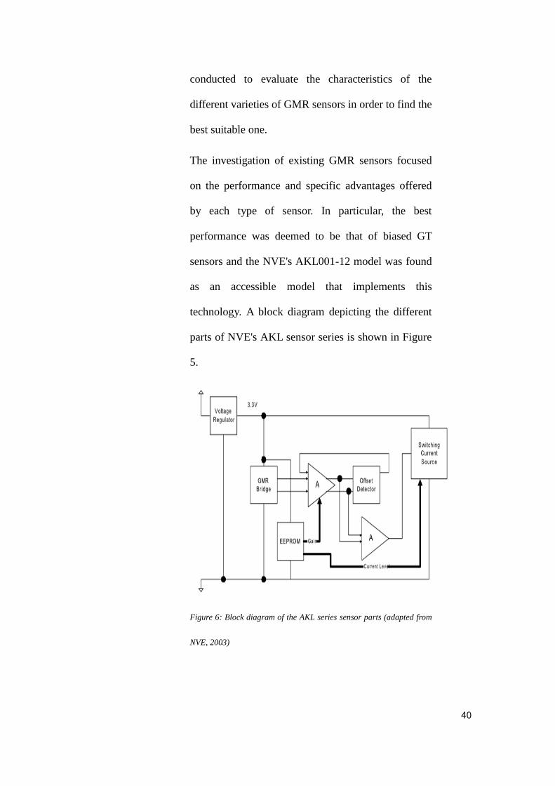
The investigation of existing GMR sensors focused
on the performance and specific advantages offered
by each type of sensor. In particular, the best
performance was deemed to be that of biased GT
sensors and the NVE's AKL001-12 model was found
as an accessible model that implements this
technology. A block diagram depicting the different
parts of NVE's AKL sensor series is shown in Figure
5.
Figure 6: Block diagram of the AKL series sensor parts (adapted from
NVE, 2003)
41
The AKL sensor series essentially provide a pulse
output signal with the high value corresponding to a
gear tooth passing in front of the sensor and a low
value corresponding to the gear tooth moving away
from the sensor. This results in a train of pulses that
can be used to easily determine the speed of the gear.
The difference between the various models in the
AKL series consists in the different spacing of
elements, ranging from 1000 microns for the
AKL001-12 to 300 microns for the AKL003-12. In
turn, this determines the pitch range of gear teeth for
which the sensor can be used. Due to the
characteristics of the gear wheel used for testing (as
described in chapter 4), the AKL001-12 model was
chosen, as it is useful for a pitch of 2.5 to 6mm (NVE,
2003).
The main advantages of the chosen type of sensor
and in particular of the AKL001-12 model are the
following (NVE, 2003):
1. Frequency of output signal that is proportional
to the speed of the rotating wheel.
2. Up to 10kHz frequency response,
corresponding thus to the speed of 500km/h.
3. Effective protection against electromagnetic

42
interference from other sources.
4. Maximum air gap of 6mm.
5. 50% duty cycle.
6. Zero speed operation.
7. Precise spacing between sensor elements.
8. Excellent temperature and voltage
performance.
9. Small, low profile surface mount package.
Despite the above advantages, the chosen sensor also
has several disadvantages: sensitivity to the position
of the magnet with respect to the sensor, sensitivity to
mechanical imperfections on the surface of cheap
magnets, sensitivity to high temperature of the
environment (NVE, 2003). Consequently, the next
design decision was to use this type of sensor in a
head array configuration using the three-channel
method, in order to mitigate the potential negative
impact of these drawbacks.
The head array configuration consists of four GMR
sensors heads (including each a permanent magnet
and the corresponding GMR components) that allow

43
thus the data to be collected at four different points.
In turn, this means that each change of the gear
position would result in four different signals being
provided by the sensor array, which allows the
correction of any bias or instability caused by the
potential wobble of the gear or a change in the
position of the magnet with respect to that of a sensor.
However, in order to make such correction, the
design of the control unit had to be changed
accordingly. More details on the design of the control
unit are provided in subsection 3.2.3 below.
3.2.2 Wireless Transmission System
The wireless transmission system consists essentially
of a wireless transmitter located by the sensors and a
wireless receiver on the other side, by the control unit.
The main rationale for exploring the switch from
wired to wireless transmission in the ABS was that it
increases the flexibility by allowing simple use of
many different types of sensors, even simultaneously,
as the signals from all sensors can be combined
together for transmission and then separated for
further processing and decision making by the control
unit's processing circuits. Thus, the use of wireless

44
transmission would enable new ABS systems that
gather additional detailed information on a variety of
aspects such as air pressure in the wheels,
temperature, or distance. This kind of additional
information can help the control unit to make better
decisions that take into account all those aspects and
thus improve the driving experience and safety at the
same time.
In addition to the above, another important reason for
exploring the use of wireless transmission in ABS is
that current wireless technology offers good stability
and a transmission speed comparable to that of a
wired system. Consequently, there seem to be few
drawbacks to the use of wireless, while the
advantages could be significant.
For the best design, the choice was made to use the
ER400TS-02 transmitter and its corresponding
receiver ER400RS-02. The chosen transmitter and
receiver are part of the ERx00-02 series provided by
Low Power Radio Solutions (LPRS, 2005). They are
very simple radio devices with a range of 250 metres
(line of sight) and allowing the optimisation of
frequency, data rate and power output to fit a
45
particular use (LPRS, 2005). In addition, they are
configurable to a certain extent by using the
embedded software that is provided with them. The
block diagrams are provided in Figure 6 and Figure 7
respectively, while the characteristics of these devices
are the following (LPRS, 2005):
1. High sensitivity at the receiver, with the
specification indicating 103dBm at 19.2Kbps
2. A maximum of 10mW transmit power at
434MHz.
3. Frequency accuracy ensured through the use of
a crystal controlled synthesizer.
4. Low power consumption (between 21 and
25mA) and operating voltage (2.5-5.5V)
5. Software adjustable BAUD rate and channel
frequencies
6. Configurable power settings for each channel
7. Software error checking and encryption
possibility

46
Figure 7: Block diagram of wireless transmitter from ER400TS-02,
used in the proposed design (adapted from LPRS, 2005)
Figure 8: Block diagram of wireless receiver ER400RS-02, used in the
proposed design (adapted from LPRS, 2005)
The above transmitter and receiver were chosen
mainly for their simplicity, ease of use and flexibility
of configuration. However, in order to integrate them
47
into the proposed design, several parameters had to
be set and the interfacing with the head array sensors
had to be done.
The parameters to set for the wireless system were
the following: data rate, transmitter and receiver
frequency, output power. All parameters were set
using the provided software located in the file ER
V2_03.exe. The data rate was set to 19200
(ER_CMD U4 constant in the software), the
frequencies were set to 434MHz (ER_CMD C7) and
the output power was set to 10mW (ER_CMD P9).
In principle, the transmitter would be directly linked
to the sensor, receiving thus the sensor's output and
simply transmitting it further to the receiver.
Similarly, the receiver would just get the transmitted
signal and pass it to the central control unit. However,
a direct connection between the array sensor
configuration and the transmitter is neither possible
nor entirely desirable. Consequently, the signals from
the array sensor are first filtered through a voltage
comparator and then processed by a specifically
programmed microcontroller before being actually

48
fed into the transmitter for wireless transmission. The
role of each of those components is explained below.
The reason for using a voltage comparator to filter
the direct output of a sensor array is to ensure that the
signal is basically in the correct format and range
accepted by the microcontroller. This means in
particular that the analogue signal provided by the
sensor is transformed into a digital signal with values
chosen in the range of the microcontroller by
comparison of the original signal to a reference
voltage. The signal processing is done by using a
high speed voltage comparator, namely the LM211
chip (Texas Instruments, 2004). The LM211 chip is
chosen as it is a simple chip used for automotive
applications, which satisfies the requirements of its
intended use in this design: it operates within the
ranges required by the sensor's output signal on one
hand and the microcontroller's input range on the
other. Thus, the LM211 is wired so that it collects the
signal from the sensor on its port 3, compares it with
the reference signal provided on port 2 and then it
feeds the result to the MCU chip AT89C52. The
signal processing circuit for LM211 is shown in
Figure 8.

49
Figure 9: Processing circuit for signal comparison with LM211 chip,
used in the proposed design (adapted from LPRS, 2005)
After the signal is processed by the LM211, it is fed
into the MCU chip AT89C52. The purpose of this
MCU is essentially to transform the signal into the
TXD mode required by the wireless transmitter. Thus,
the MCU is wired between the LM211 and the
transmitter, as shown in Figure 9. Both the wireless
receiver and wireless transmitter are shown in Figure
10.

50
Figure 10: Partial circuit diagram showing the connection of the
wireless transmitter to the MCU AT89C52 that transforms the signal
into the TXD mode required for wireless transmission (adapted from
LPRS, 2005)

51
Figure 11: Partial circuit diagram, showing the wireless transmitter
(receiving its input signal from the MCU AT89C52 on port 5) and
wireless receiver (forwarding the signal to the 80C196KC control unit)
3.2.3 Controller (Control Unit)
The last main component of the proposed design is
the main control unit represented by the Intel MCU
80C196KC chip. This chip was selected as it is
commonly used for processing of wheel speed signal
inputs. The Intel 80C196KC chip (Intel, 1991) is a
16-bit, high-performance microcontroller with four
high-speed inputs (HSI), HSI0 to HSI3. The
microcontroller also has the following features: HSI
gating logic, eight divided counters, an input
transition detector, FIFO interrupt and control logic,
FIFO registers, HSI time to register, HSI way and
HSI status registers' registers (Intel, 1991).
52
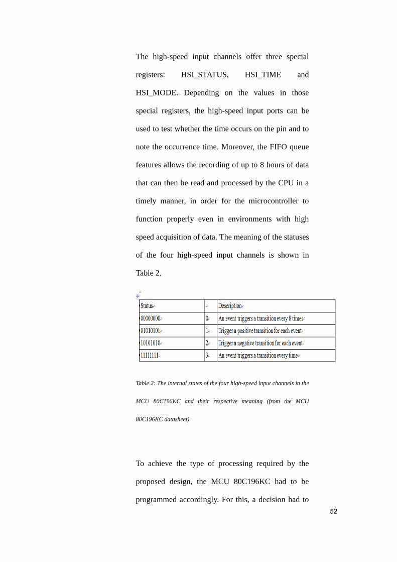
The high-speed input channels offer three special
registers: HSI_STATUS, HSI_TIME and
HSI_MODE. Depending on the values in those
special registers, the high-speed input ports can be
used to test whether the time occurs on the pin and to
note the occurrence time. Moreover, the FIFO queue
features allows the recording of up to 8 hours of data
that can then be read and processed by the CPU in a
timely manner, in order for the microcontroller to
function properly even in environments with high
speed acquisition of data. The meaning of the statuses
of the four high-speed input channels is shown in
Table 2.
Table 2: The internal states of the four high-speed input channels in the
MCU 80C196KC and their respective meaning (from the MCU
80C196KC datasheet)
To achieve the type of processing required by the
proposed design, the MCU 80C196KC had to be
programmed accordingly. For this, a decision had to

53
be made first with respect to the programming
language chosen for this task: either assembly
language or C. Programming in assembly language is
in general more tedious and results in larger, although
potentially more efficient code. On the other hand,
programming in C is faster, easier and tends to result
in shorter code. Given that the programming was
realised here for a prototype project, the C language
was chosen to program the microcontroller, as the
speed and facility of programming were more
relevant for this type of project than a potential
improvement of performance due to careful tuning of
assembler code.
For the programming of the microcontroller, the
standard Keil software (ARM, n.d.) suite was used.
Keil is useful as it can simulate peripherals and thus it
provides a virtual environment in which initial tests
can be made quickly and efficiently. The overall
workflow of the processing implemented for the
MCU 80C196KC is shown in Figure 11. The
implementation consists in eight distinct functions, as
follows:

54
1. Main function (located in Main.c file)
2. ABS main function (located in ABS_main.c
file)
3. Input and output port initialisation function
(located in io.c)
4. GPT1 unit interrupt function (located in
GPT1.c)
5. GPT2 unit interrupt function (located in
GPT2.c)
6. CC1 wheel speed interrupt processing function
(located in CC1.c)
7. CC2 wheel speed interrupt processing function
(located in CC2.c)
8. Fast external interrupt initialisation function
(located in int.c)

55
Figure 12: Flow chart showing the overall workflow implemented for
the MCU 80C196KC (adapted from Keil 8051 Microcontroller
Development Tools, 2012)
3.3 Design validation
The overall aim of design validation was to ensure
that the proposed GMR ABS worked properly and
behaved as expected. For this aim, a simulation
environment was used as the cheapest and simplest

56
solution available that was also entirely adequate.
The system was split into its main component parts
and the simulator was run for each of them, to ensure
that the generated outputs corresponded to the
expected ones, given the inputs provided. In
particular, the following different parts were tested in
a simulation environment: the MCU signal process
circuit, the solenoid valve control circuit and the
pump motor control circuit.
The following sections describe the choice of
simulation environment as well as the simulation
setup and results obtained for each of the three main
parts of the proposed GMR ABS.
3.3.1 Simulation environment
For validating the proposed GMR ABS, the Protel 99
SE (Protel, 2001; Altium Ltd., 2001) circuit design
and simulation software was chosen. The choice was
motivated by the fact that Protel99SE fully supported
the design and validation process from the first steps
of building the needed circuits to the last steps of
actually specifying inputs and testing various parts of
the whole system as well as the system as a whole. In
57
particular, the simulation environment offered a
convenient way of simulating the design of the
printed circuit board (PCB) in its entirety, ensuring
signal integrity as well as electrical connectivity
throughout. In turn, this meant a higher confidence in
the simulation results as correct indicators of the
validity of the GRM ABS design, since the
implementation afterwards in a prototype was
straightforward.
Additional characteristics of Protel 99 SE that make it
an adequate choice for design validation of the
proposed GMR ABS are the following: convenient
access to the complete set of tools that were needed
for both design and validation phases, including for
instance the schematic editor, mixed-signal circuit
simulator and Signal Integrity Analysis tool (Altium
Ltd., 2001); design database allowing easy storage
and access of different versions of the design as well
as its component parts (Altium Ltd., 2001);
comprehensive and up-to-date component libraries
containing all the required component for the
proposed GRM ABS.

58
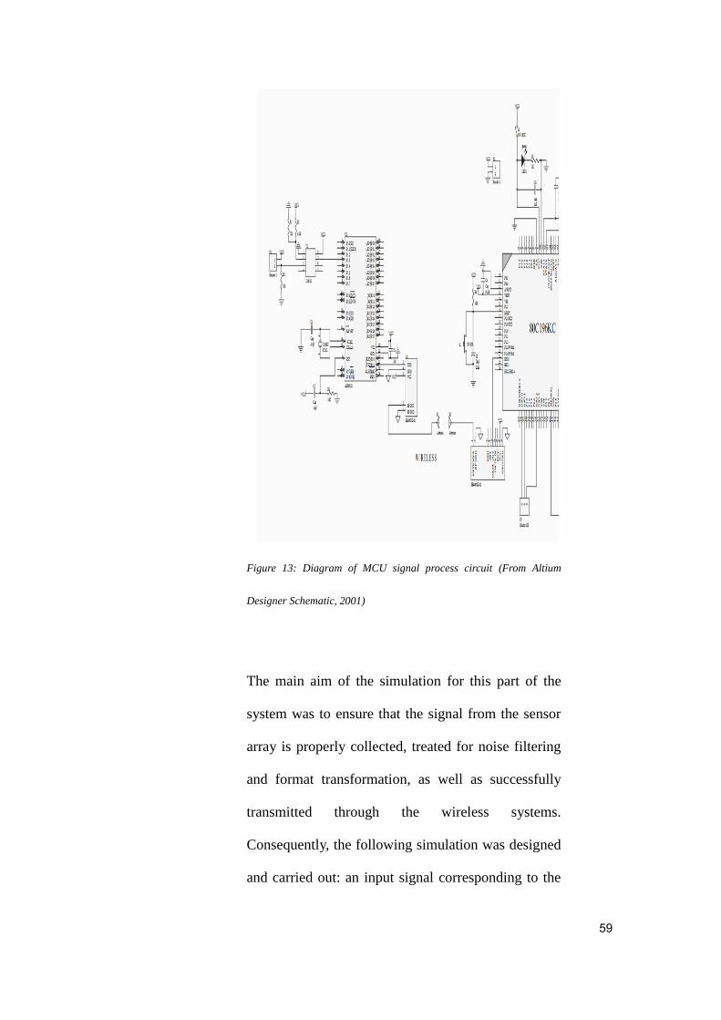
3.3.2 Simulation of MCU signal process circuit
The diagram of the MCU signal process circuit is
shown in Figure 12, using the exact components
previously described in the overall system's design.
As detailed in the presentation of the system's design,
the MCU signal process circuit includes all the
components required to collect the information from
the sensor array, filter it and transform it to the right
format for further processing, transmit it in a wireless
manner to the MCU and finally make decisions based
on it, according to the logic coded into the MCU
80C196KC.
59
Figure 13: Diagram of MCU signal process circuit (From Altium
Designer Schematic, 2001)
The main aim of the simulation for this part of the
system was to ensure that the signal from the sensor
array is properly collected, treated for noise filtering
and format transformation, as well as successfully
transmitted through the wireless systems.
Consequently, the following simulation was designed
and carried out: an input signal corresponding to the

60
sensor's output is applied and the resulting signal is
then visualised at the various significant points of the
circuit. The values used and results obtained are
detailed below.
To simulate the sensor's activity, an input signal
generator is used, providing a peak to peak 5V sine
signal, as shown in the image of the first oscilloscope
XSC1 in Figure 13. This corresponds directly to what
the sensor array is expected to provide when the
wheel is moving. The actual frequency of the sine
signal corresponds to the speed of the wheel.
However, the actual functioning of the sensor itself
could not be tested through the simulation and is
tested instead directly on the lab prototype of the
system, described in the evaluation section 3.4 below.
During this simulation, the sensor output is
considered to correctly represent the wheel's actual
movement and the focus is instead on ensuring that
successive transformations of this signal are correct.

61
Figure 14: Simulation settings and results for the MCU signal circuit
(From Altium Designer Schematic, 2001)
The first transformation to check is the noise filtering
of the signal and its transformation to the range
accepted by the MCU. This is basically done through
comparison with a reference signal and the result is
shown in the image of the second oscilloscope, XSC2,
in Figure 13 above. Finally, the signal is filtered and
transformed to a regular square waveform that is
accepted as input by the MCU, as shown in the
remaining oscilloscope images in Figure 13.

62
3.3.3 Simulation of the solenoid valve control circuit
The simulation of this part of the system was mainly
done to ensure the compatibility with the chosen
MCU design, as well as the correct implementation
of this part of the circuit. An important issue was to
ensure that the signal obtained was strong enough to
properly drive the solenoid valve. Consequently, the
test consisted in simulating the path of the signal
from the MCU through a hex inverter and an
opto-transistor to the solenoid valve, as shown in the
circuit diagram in Figure 14, and measuring the
current obtained, comparing it with the required
range specified in the valve's datasheet. For the
purpose of the simulation, the solenoid valve's coil
was simulated using a resistor. The corresponding
simulation setup and results are shown in Figure 15.
As it can be seen from the measurements in the figure,
the current obtained is strong enough to drive the
solenoid valve properly, according to its
specification.

63
Figure 15: The control circuit of the solenoid valve. (From Altium
Designer Schematic, 2001)
Figure 16: Simulation setup and results for the solenoid valve circuit
(From Altium Designer Schematic, 2001)

64
3.3.4 Simulation of the pump motor control circuit
The pump motor control circuit is especially
important as it basically determines whether the ABS
is ultimately functional or not: its role is to ensure
that the decisions and commands of the controller are
effectively transmitted to the pump motor in order to
be carried out. Consequently, the main aim of this
simulation was to ensure that the decisions of the
ABS controller are transmitted in a format
compatible with that required by the pump motor. An
initial run of the simulation showed that the signal
needs to be amplified in order to fit into the range
most suitable for the pump motor used. Consequently,
an amplifier was used and the final setup and results
of the simulation are shown in Figure 16 below.

65
Figure 17: Simulation setup and results for the pump motor circuit.
(From Altium Designer Schematic, 2001)
3.4 Design Evaluation
After the successful validation of the design, the next
step was to implement it as a lab prototype and
evaluate its performance through some
comprehensive tests. The implementation itself
consisted in a soldering of all the components
required on a PCB board, according to the previously
validated design. However, for testing purpose, there
was a need also for an experimental setup using a
metal gearwheel. The following two subsections
describe the PCB board implementation as well as the

66
experimental setup and materials used. The tests and
results are then presented and discussed in the
remaining subsections of this section.
3.4.1 PCB Board Implementation
A PCB board was used to bring together all the parts
of the proposed GMR ABS design. The overall result
is shown in Appendix X. The system basically is
made of four distinct parts: signal acquisition, signal
processing, solenoid valve control and pump motor
control. The following paragraphs describe each of
these in detail.
The following is a block diagram of the overall
system:
Figure 18: Block Diagram of Overall Circuit
Pump Motor
Control Circuit
Solenoid
Valve Control
Circuit
MCU
Circuit Power
Supply
Signal Processing

67
As its name suggests, the role of the signal
acquisition part of the design is to reliably collect
information from the wheel, regarding its movement.
This part includes the GMR sensor array as the actual
signal generator, as well as the components that filter
and transform the original signal for effective further
processing, up to the wireless transmitter. A photo of
this part of the prototype is shown in Figure 18.
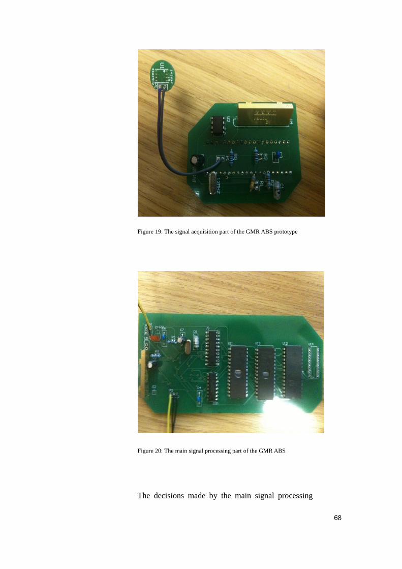
The second part of the prototype is the main signal
processing part. This part receives as input the final
signal transmitted by the previous part and it uses it
to effectively decide on what action (if any) should be
taken. Consequently, the components that make this
part are the following: the wireless receiver, the
80C196KC MCU, programming counters and data
storage memory. A photo of the main signal
processing part is shown in Figure 19.
68
Figure 19: The signal acquisition part of the GMR ABS prototype
Figure 20: The main signal processing part of the GMR ABS
The decisions made by the main signal processing

69
part of the prototype are then transmitted as
commands to the solenoid valve control part. This
part includes the phototransistor, hex inverter and
channel to the hydraulic valve. This part of the
prototype is shown in Figure 20.
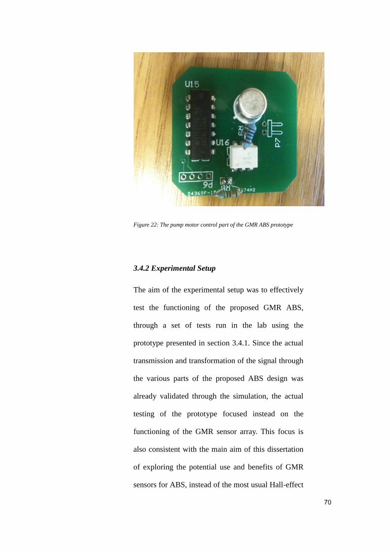
The last part of the prototype is the pump motor
control part, including the phototransistor, hex
inverter and link to the solenoid drive, as shown in
Figure 21.
Figure 21: The solenoid valve control part of the GMR ABS prototype
70
Figure 22: The pump motor control part of the GMR ABS prototype
3.4.2 Experimental Setup
The aim of the experimental setup was to effectively
test the functioning of the proposed GMR ABS,
through a set of tests run in the lab using the
prototype presented in section 3.4.1. Since the actual
transmission and transformation of the signal through
the various parts of the proposed ABS design was
already validated through the simulation, the actual
testing of the prototype focused instead on the
functioning of the GMR sensor array. This focus is
also consistent with the main aim of this dissertation
of exploring the potential use and benefits of GMR
sensors for ABS, instead of the most usual Hall-effect
71
sensors.
To be able to evaluate the functioning of the sensor
itself however, a laboratory setup had to be designed
so that the signal is directly collected by the sensor
array. Since a full setup involving a motor and wheel
was not available, a decision was made to use a more
minimalistic, but still adequate setup instead: a metal
gearwheel that could rotate on an axis at various
speeds and permitting the attachment of the sensor so
that different values for the air gap can be
experimented with.
The characteristics of the gearwheel can greatly
influence the test results and therefore the wheel used
for testing was chosen carefully to fit the
characteristics of the GMR sensor and to allow at the
same time the desired variations of speed and air gap.
In particular, the following characteristics were taken
into consideration: circular pitch, circular thickness,
face width, chordal pitch, and addendum. The shape
and strength of the gearwheel are less important for
this evaluation, given that the tests focus solely on the
behaviour of the sensor at various speeds and air gaps.
Nevertheless, a trapezoidal steel gearwheel was

72
chosen, as it is quite common. Figure 22 shows the
actual gearwheel that was used for testing.
Figure 23: The gearwheel used for testing the proposed GMR ABS
The gearwheel used for testing has 100 gears around
the wheel, an internal diameter of 80.5 mm and an
external diameter of 120mm, resulting in a circular
pitch of approximately 3.8mm. Consequently, the
circular thickness, computed as half of the circular
pitch, is 1.9mm. These characteristics are especially
important for the choice of motor and they were
chosen to fit a motor with a diameter of 80mm.
Moreover, the number of gears around the wheel is
important to ensure that the frequency generated is
within the sensor's measurement range. The value
chosen was arrived at by considering the following

73
characteristics and formula for computing the speed:
ABS control speed: 5km/h – 300km/h
Sensor detection range: 1Hz – 10kHz
Speed: V = 2пrf/z, where r is the radius of the wheel,
z is the number of gears and f is the frequency of the
sensor's output signal.
The face width of the gears determines the type of
expected output from the GMR sensor. For good
performance and convenience of measurement of test
results, the sensor width should be approximately 4
times larger than the face width, so that a full sine
wave should be obtained on the oscilloscope's screen.
Consequently, the wheel was chosen so that its face
width is approximately 1.8mm. It is important to note
that a different wheel with a different face width
could have been chosen for testing without
significantly affecting the results in terms of actual
performance of the sensor in detecting the wheel's
movement. However, this setup was preferred simply
to have a clear and complete sine wave detected,
making the evaluation of the test's results easier.
The addendum and dedendum of the gearwheel were
74
0.8mm and 1mm respectively. Their values are not
particularly important for the type of testing
performed, but are given here in order to ensure that a
repeatability of the tests can be easily carried out.
Two tests were planned and run:
Test1: basic sensor testing at various speeds. The aim
of this test was simply to ensure that the sensor's
output is correct for various speeds.
Test2: variation of sensor output depending on air gap
at slow speed. The aim of this test was to measure
how the output signal of the sensor is affected by the
variation in air gap at a relatively slow speed.
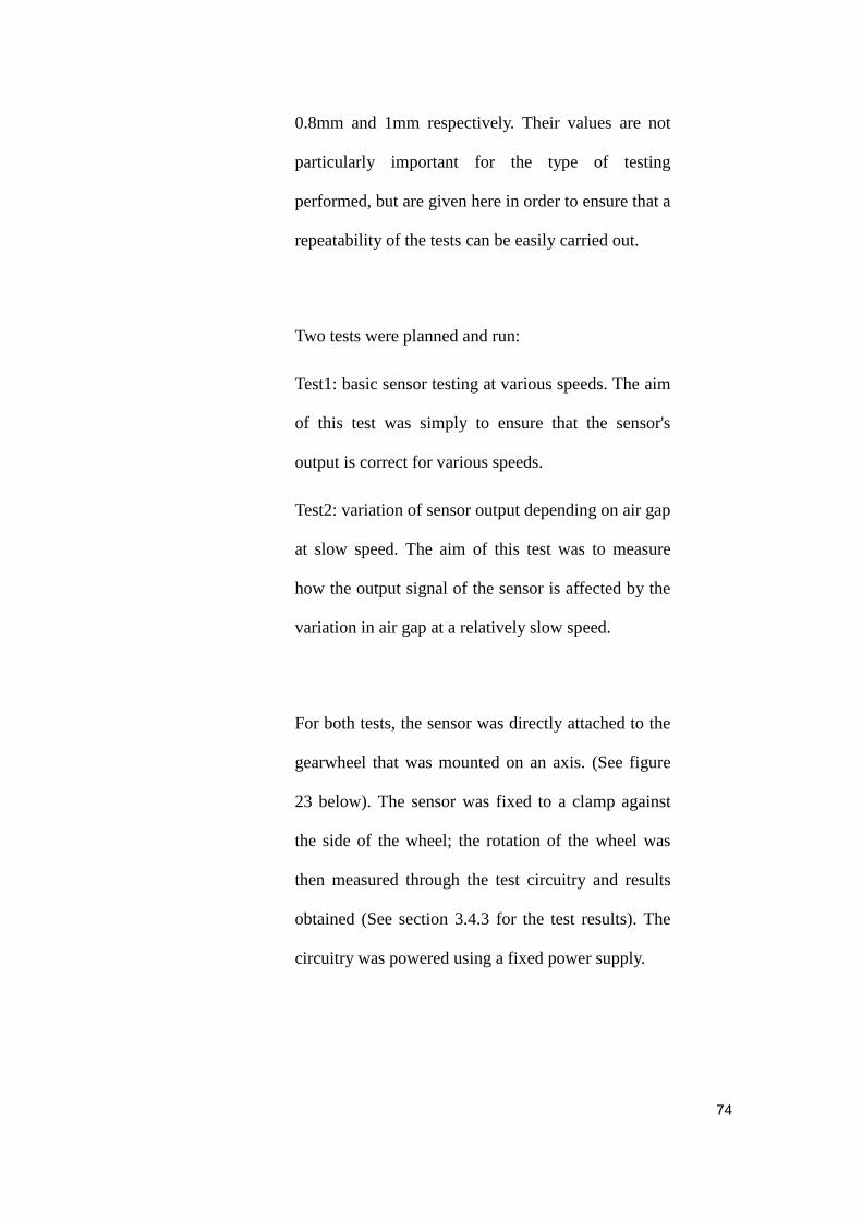
For both tests, the sensor was directly attached to the
gearwheel that was mounted on an axis. (See figure
23 below). The sensor was fixed to a clamp against
the side of the wheel; the rotation of the wheel was
then measured through the test circuitry and results
obtained (See section 3.4.3 for the test results). The
circuitry was powered using a fixed power supply.
75
Figure 24: Experimental setup showing the gear wheel and the
attachment of the sensor that is connected further to the circuit for
initial processing and wireless transmission
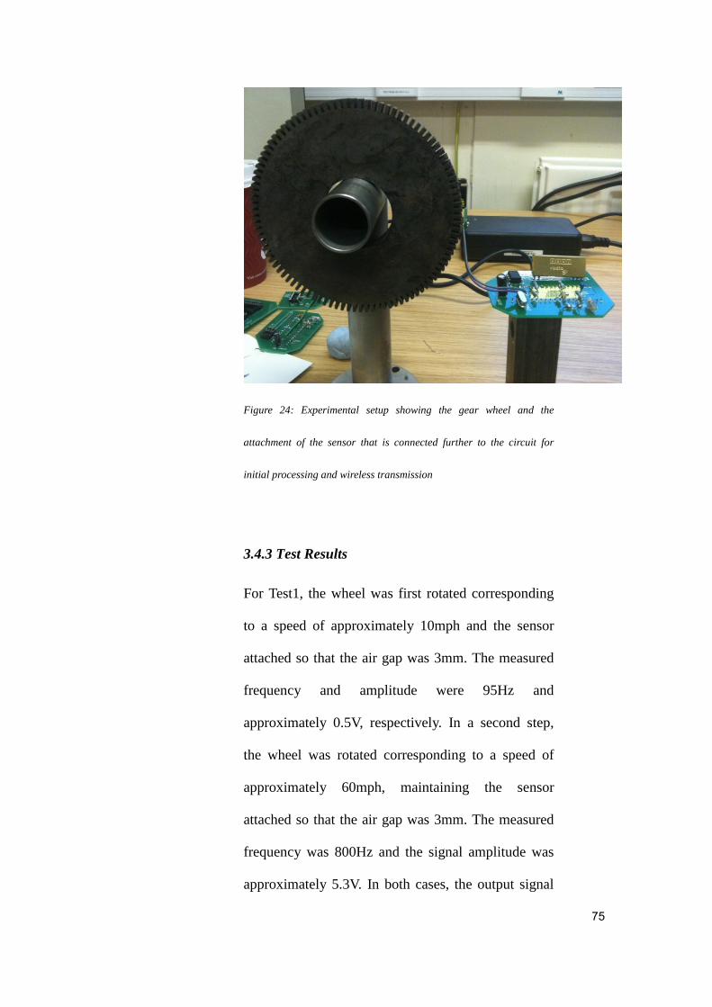
3.4.3 Test Results
For Test1, the wheel was first rotated corresponding
to a speed of approximately 10mph and the sensor
attached so that the air gap was 3mm. The measured
frequency and amplitude were 95Hz and
approximately 0.5V, respectively. In a second step,
the wheel was rotated corresponding to a speed of
approximately 60mph, maintaining the sensor
attached so that the air gap was 3mm. The measured
frequency was 800Hz and the signal amplitude was
approximately 5.3V. In both cases, the output signal

76
was consistent and maintained a good sine wave form,
as it can be seen in Figure 23, Figure 24, Figure 25
and Figure 26 respectively. The results of both
measurements for this test are summarised in Table 3
below.
Table 3: Results of Test1, measuring the sensor signal output at various
speeds and constant air gap.
For Test2, the wheel was rotated corresponding to a
speed of approximately
60mph and the sensor attached so that the air gap
variated
I
Figure 24: Oscilloscope reading for Test1, at a speed of approximately
Input signal
Output signal
77
10mph and an air gap of 3mm.
Figure 25: Drawn sine wave corresponding to output signal obtained at
10mph and 3mm air gap (Test1)
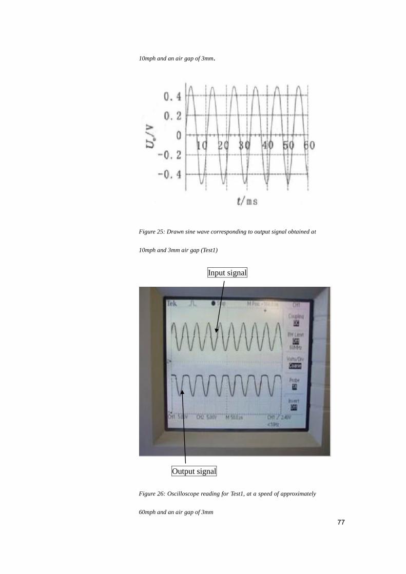
Input signal
Output signal
Figure 26: Oscilloscope reading for Test1, at a speed of approximately
60mph and an air gap of 3mm

78
Figure 27: Drawn sine wave corresponding to output signal obtained at
60mph and 3mm air gap (Test1)
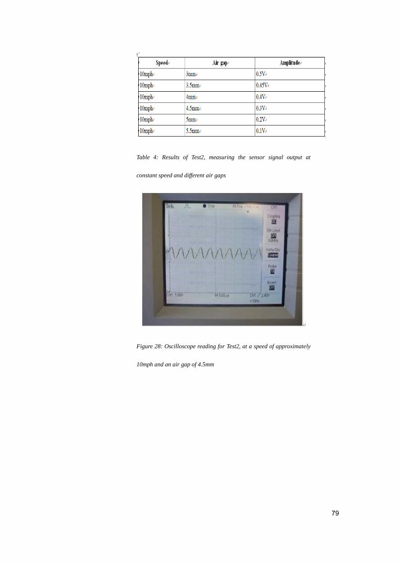
For Test2, the focus was on evaluating the sensor's
output signal at a relatively slow speed, when the air
gap changes. Consequently, the wheel was rotated at
a speed corresponding to 10mph and the output signal
was measured for an air gap increasing in 0.5mm
steps from 3mm to 5.5mm. The results are
summarised in Table 4 and shown graphically in
Figure 29 below. Two of the signal readings on the
oscilloscope are also shown in Figure 27 and Figure
28 respectively.
79
Table 4: Results of Test2, measuring the sensor signal output at
constant speed and different air gaps
Figure 28: Oscilloscope reading for Test2, at a speed of approximately
10mph and an air gap of 4.5mm

80
Figure 29: Oscilloscope reading for Test2, at a speed of approximately
10mph and an air gap of 5.5mm
3 3.5 4 4.5 5 5.5
0
0.1
0.2
0.3
0.4
0.5
0.6
Variation of sensor's output signal amplitude when the air gap increases
(speed is maintained constant at 10mph)
Amplitude (V)
Air gap (mm)
Am
plitu
de
(V
)
Figure 30: Results of Test2 showing how the sensor's output signal
amplitude decreases when the air gap is increased, although the speed
is maintained constant

81
3.4.4 Discussion of Results
The results of the two tests performed for the
evaluation of the proposed GMR ABS show that the
sensor performs well both at relatively low and at
medium speeds. In addition, the investigation of the
sensor's behaviour when the air gap increases offers
important information about the proposed system's
performance in less than ideal conditions. The
following paragraphs discuss in more detail the
results of each test.
As expected, the first test shows that, when the air
gap is maintained fairly low and constant at 3mm, the
output signal of the sensor is very clear and with an
amplitude that increases when the speed is increased
and decreases when the speed is decreased. Moreover,
the quality of the output signal from the sensor is
very good, as there are no fluctuations of the signal
and no apparent noise, as it can be seen from the
results presented in section 3.4.3 above. However, it
is worth mentioning that these results were obtained
in laboratory conditions and therefore, a use of the
proposed GMR ABS in real-life conditions might

82
reveal additional interference that can cause the
signal to jitter slightly. Nevertheless, the clarity and
persistence of the signal in laboratory conditions is a
promising result.
The second test investigated the behaviour of the
sensor when the air gap is increased. The results
essentially show that the sensor offers good and
reliable signal output for an air gap in the range of 3
to 5.5mm. Obviously, as expected, the amplitude of
the output signal decreases as the air gap is increased,
but even at 5.5mm, the signal at 0.1V amplitude is
still fairly clear and readable, as it can be seen from
the oscilloscope readings shown in section 3.4.3
above. This result is quite important as it reveals the
robustness and reliability of the GMR sensor array in
less than ideal conditions, when the air gap might
increase unexpectedly.
In all situations revealed during the testing, the GMR
sensor behaved appropriately, with no apparent loss
of signal or significant alteration that might make it
difficult for the ABS part to interpret the signal
correctly. Consequently, it can be inferred that the

83
GMR sensor array is likely to be a feasible option to
use in ABS, with quite good results. Obviously,
additional testing in a wider range of conditions is
needed in order to explore the full capabilities and
potential drawbacks of using a GMR sensor in an
ABS, but this evaluation of a prototype in laboratory
conditions shows promising results regarding the
quality of the signal and its stability in situations
when the air gap increases.

84
Chapter 4 Comparison of GMR ABS with
existing Hall ABS
Given the widespread use of Hall-effect sensors in
current ABS designs, this chapter aims to provide a
short comparison of the proposed GMR ABS design
with the known performances of Hall-effect ABS
designs. In particular, the comparison focuses on how
each type of sensor performs when the air gap
increases.
According to existing literature, the GMR sensor
should supposedly offer higher sensitivity compared
to Hall-effect sensors. In practice, this should be
noticeable through a better quality of the output
signal even when the air gap increases. According to
the Hall sensor data book, the usual air gap range for
which a Hall-effect sensor still offers clear output
signal is 0.4mm to 2.5mm (Honeywell, n.d.). By
comparison, a GMR sensor supposedly has a range of
1.1mm to 6mm air gap (Honeywell, n.d.).
As it can be seen from the evaluation presented and
discussed in the previous chapter, the output signal

85
from a GMR sensor is in fact very strong and clear
for air gaps between 3mm and 5.5mm, although at
5.5mm the amplitude of the signal becomes very
small. This effectively means that the GMR sensor is
indeed capable of better detecting the wheel
movement even at air gaps larger than the 2.5mm
accepted by a Hall-effect sensor. In addition, when
the air gap is around 3mm, the sine wave of the GMR
sensor's output signal is very clear and easy to detect
and interpret. Consequently, it can be inferred that the
GMR sensor can indeed be successfully used for an
ABS to increase its performance when the air gap is
larger than that for which a Hall sensor can still
produce good output signal.
An additional benefit of the GMR sensor that can be
inferred from its observed performance during the
evaluation is the lower rate of jitter compared to a
Hall-effect sensor. Although the jitter was not
measured during the evaluation performed for this
dissertation, it is known that the higher the sensitivity
of a sensor, the lower its jitter. Consequently, given
the observed higher sensitivity of the GMR sensor
compared to the Hall-effect sensor, it can be
reasonably inferred that the GMR sensor is likely to

86
be less affected by jitter as well in situations when the
Hall-effect sensor's output might be badly affected by
it. This inferred statement is also supported to some
extent by the observation that there was little
noticeable jitter during any of the situations
investigated for the evaluation of the GMR ABS
prototype.
87
Chapter 5 Limitations
The results of this dissertation have to be considered
taking into account a series of limitations due mainly
to the experimental setup for validation and
evaluation. This chapter aims to present and describe
the main limitations as well as their potential impact
on the applicability of the findings.
The proposed GMR ABS design is meant to explore
the use of any GMR sensor for potential
improvement of ABS that is used in the automotive
industry. However, for practical reasons, the
simulation as well as the implementation of the
prototype is made with a set of components.
Consequently, the findings regarding the sensitivity
of the GMR sensor and in particular its good
performance in case of increased air gaps have to be
interpreted as representative foremost of the
components used for to implement the prototype.
Generalising these findings to all GMR sensors might
not be entirely reliable, as there might be
configurations that are more sensitive to interferences
for instance or that might be less adequate for certain
values of the air gap.
88
Another important characteristic of the prototype
evaluation performed for this dissertation is the fact
that a specific configuration of the GMR sensors was
used. Therefore, the results obtained are to be
considered an indication of the performance of this
configuration, rather than a more general indication
of GMR sensors as a technology. However, this is not
a limitation in itself of the study, given that the
purpose was exactly to explore possibilities of using
GMR sensors for ABS design improvement, rather
than exploring the GMR technology as a whole.
Another limitation of this study is given by the
laboratory conditions of the prototype evaluation that
was performed. Due to limited resources available, a
minimal prototype was built, rather than a
fully-working prototype complete with motor and
other components. This however limited to some
extent the amount and type of testing that could be
performed. For instance, there were limited
possibilities to adjust and control the speed of the
wheel and, consequently, tests were performed for
only two speeds rather than on a larger range.

89
In addition to the above, the setup limited the
possibilities of ensuring with high accuracy the
constant speed of the wheel. Consequently, the results
have to be considered taking into account potential
small variations of the speed during the measurement.
This was addressed in part by repeating several times
each test and measurement so that the results are
proven to be repeatable, but nevertheless, a more
rigorous control of the speed would have allowed
more precise evaluations of other characteristics as
well, such as jitter or potential interferences.
Finally, the validation and evaluation of the proposed
design focused mainly on the sensor part given that
this was the most important novelty proposed.
Consequently, the results obtained and discussed in
this dissertation are to be considered an indication of
the potential improvements that can be obtained from
using GMR sensors in the given configuration, rather
than an indication of the potential overall
performance of the proposed ABS design. As
discussed in the following chapter, further
investigations should be carried out for a more

90
thorough evaluation of the proposed design as a
whole. Nevertheless, it is important to note that the
simulation (by contrast to the actual prototype testing)
was performed for the design as a whole and
therefore it offers reliable proof of the validity of the
design in all its parts.
91
Chapter 6 Conclusions and Future Work
This dissertation explored potential ways to improve
the performance of ABS in the automotive industry,
focusing especially on the practical use of GMR
sensors instead of the widespread Hall-effect sensors
and the use of wireless instead of wired transmission
of signal data from the sensor to the signal processing
and decision part of the ABS.
There are three main contributions made by this
dissertation to the body of existing work:
1. An overview of the various types of sensors
that are or can be currently used for ABS design,
discussing the underlying technology of each as well
as their known strengths and weaknesses with respect
to potential use in the automotive industry. This
overview can help a newcomer to the field to get a
clear picture of the main current technologies and the
situations in which they can be of use. Moreover, the
overview identified GMR sensors as a potential
improvement over the most common Hall-effect
sensors for use in ABS design. Based on the
characteristics of the underlying technology for both
types of sensors, the main expected improvement of

92
replacing Hall-effect sensors with GMR sensors was
a better sensitivity that allows accurate information to
be collected and transmitted to the ABS system even
in adverse situations such as large air gaps that can
otherwise compromise the output of Hall-effect
sensors.
2. A proposed GMR ABS design that effectively
illustrates a potential use of GMR sensors and
wireless transmission in a practical ABS. This design
provides working solutions for various
implementation issues. Such solutions include for
instance an efficient working configuration for an
array of GMR sensors and the needed circuits to
process and transform the output signal so that it can
be wirelessly transmitted and further processed and
interpreted by the main control unit of the ABS. In
addition, the design is fully validated through a
simulation that involves all its component parts. A
working prototype is then implemented and
physically tested in the laboratory, providing
measurements and proofs of the functioning of the
GMR sensor at various speeds and different air gaps.
3. A comparison of the observed (measured)
characteristics of the GMR sensor's performance in
the proposed ABS design with the known
93
characteristics of standard Hall-effect sensors. This
can help the industry as well as any other stakeholder
who is interested in potential alternatives to
Hall-effect sensors, effective ways to improve the
performance of an ABS design.
The main finding of this dissertation is that GMR
sensors and wireless transmission can indeed be
successfully used to improve the sensitivity of ABS.
The full design developed, combined with the
validation and evaluation results offer proof that this
is indeed the case. However, the work presented in
this dissertation should be considered as only an
initial step towards the full exploration of the
potential of GMR sensors for improving the
performance of ABS. Considering the exploratory
nature of the work, its results are meant primarily as
initial proofs of the validity and potential of the
approach, rather than definite evidence of the exact
improvements to be gained from the use of GMR
sensors and wireless transmission in the design of
ABS. For such definite evidence to be obtained,
several directions should be further explored in future
work that can build on the results of this dissertation,
as described in more detail in the following

94
paragraphs.
The first direction of future work that stems from this
dissertation is the more detailed and thorough
evaluation of the behaviour of GMR sensors in
implementations of ABS and in real-life situations.
The results of the laboratory evaluation showed better
sensitivity and clear, jitter-free output signal from the
sensor array. However, a more complete prototype
should be built and tested in a variety of situations
including for instance variations of temperature,
extreme road and speed conditions as well as
potential interferences from other sources. Moreover,
the actual performance of the GMR sensor array
should be further assessed on all the expected range
of speed and air gaps that could occur in-use
situations. This would offer a more comprehensive
image of the actual improvements offered by the use
of GMR sensors as well as valuable information
regarding any potential drawbacks or situations when
the GMR sensor array might offer a less clearer or
reliable signal than expected.
Another important aspect that would benefit from

95
future work is the testing of the wireless transmission
used in the proposed GMR ABS design. The
simulation validated the complete design, but it could
not take into account for traffic situations and the
potential interference that might obstruct or otherwise
reduce the efficacy of the wireless transmission.
Consequently, future work should focus on testing
thoroughly this part of the proposed design as well, in
order to ensure that the wireless transmission is
equally reliable to a wired one even in extreme traffic
situations when the ABS is often most needed to
avoid potential accidents. Such testing could also
reveal potential issues with the wireless transmission
that were not obvious during the validation and
evaluation performed as part of this project, given the
laboratory conditions and limited resources available.
Nevertheless, a thorough evaluation of the wireless
transmission is certainly needed before it can be
considered as a fully safe alternative to replace
cumbersome wired transmission in mass produced
ABS designs.
The work done for this dissertation essentially offers
one effective way in which GMR sensors can be used
to enhance ABS design. However, the sensor array
proposed as well as the configuration used are not

96
necessarily the only possible or even most efficient
ways of harnessing the benefits of GMR sensors for
improved ABS performance. Therefore, another
direction for future work would be to explore the
performance of other configurations or other potential
ways in which GMR sensors could improve the
functionality of an ABS. For instance, the higher
sensitivity of the GMR sensor compared to the
Hall-effect sensor basically offers more precise
information to the main control circuit of the ABS
and such information could in turn be used to take
more precise and more effective decisions in
potentially dangerous traffic conditions to improve
both the safety and convenience of driving.
Finally, another direction for future work would be
the more detailed comparison of GMR and
Hall-effect sensors when used for ABS design. The
comparison performed for this dissertation was
limited by the relatively little information available
from the experimental setup. Although useful with
respect to comparing the sensitivity of the two types
of sensors, a more comprehensive comparison would
be needed in order to fully inform a potential decision
of using one sensor type or the other in an ABS

97
design. First of all the comparison of sensitivity itself
could take for instance into account more variate
operation conditions including a wider range of
speeds and air gaps as well as interferences that can
introduce jitter or otherwise affect the quality and
adequacy of the information obtained and transmitted
by each type of sensor in a real-life situation of use in
traffic. Second, a comprehensive comparison should
also include other aspects such as the behaviour of
the two types of sensors in extreme conditions and
their resilience to unexpected situations as well as
their stability of operation in time or over extended
periods of intensive use.
Overall, the work presented in this dissertation
represents an initial successful exploration of some of
the ways in which current ABS design can be
improved through the use of GMR sensors and
wireless communication. As reflected in the variety
of directions available for future work, the results of
this dissertation open a large number of paths that can
lead to potentially significant improvements of ABS
design that can result in both safer and more
enjoyable driving, adequate for the increasingly
complex traffic situations that are current on modern

98
roads all around the world.

99
Bibliography
Altium Ltd. (2001): Protel99SE: The Complete
Board-Level Design System for Windows 95, 98 and
NT. [online] Available at:
<www.altium.com/files/protel/legacy/handbookp99se
.pdf >
ARM (n.d.): Keil 8051 Microcontroller Development
Tools. [online] Available at:
<http://www.keil.com/c51/>
Barnard, Y., Risser, R. and Krems, J. eds. (2011): The
Safety of Intelligent Driver Support Systems: Design,
Evaluation and Social Perspectives. Farnham, Surrey:
Ashgate.
Brookhuis, K.A. and de Waard, D. (2010):
Monitoring Drivers' Mental Workload in Driving
Simulators using Physiological Measures. Accident
Analysis and Prevention, 42, pp. 898-903.

100
Brookhuis, K.A. and de Waard, D. (2007): Intelligent
Transport Systems for Vehicle Drivers. In: T. Garling
and L. Steg, eds. 2007. Threats from Car Traffic to
the Quality of Urban Life: Problems, Causes, and
Solutions. Oxford, England: Elsevier.
Brookhuis, K.A., de Waard, D. and Janssen, W.H.
(2001): Behavioural Impacts of Advanced Driver
Assistance Systems – an Overview. European
Journal on Transportation and Infrastructure
Research, 1(3), pp. 245-253.
Buciu, I., Gacsadi, A. and Grava, C. (2010): Vision
Based Approaches for Driver Assistance Systems. In
ICAI'10 Proc. Of the 11th
WSEAS International
Conference on Automation and Information.
Caruso, M., Bratland, T., Smith, C. and Schneider, R.
(1998): A New Perspective on Magnetic Field
Sensing. In SENSORS Magazine, December 1998,
pp. 34-45.
Coehoorn, R. (2003): Giant Magnetoresistance and
Magnetic Interactions in Exchange-Biased
Spin-Valves. In: K.H.J. Buschow, ed. 2003 Handbook
101
of Magnetic Materials. Amsterdam: Elsevier.
Fleming, W. J. (2001): Overview of Automotive
Sensors. IEEE Sensors Journal, 1(4), pp. 296-308.
Grunberg, P., Schreiber, R., Pang, Y., Walz, U.,
Brodsky, M.B. and Sowers, H. (1987): Layered
Magnetic Structures: Evidence for Antiferromagnetic
Coupling of Fe Layers across Cr Interlayers. In
Journal of Applied Physics, 61(8), pp. 3750-3752.
Grunberg, P., Schreiber, R., Pang, Y., Brodsky, M.B.
and Sowers, H. (1986): Layered Magnetic Structures:
Evidence for Antiferromagnetic Coupling of Fe
Layers across Cr Interlayers. In Physical Review
Letters, 57(19), pp. 2442-2445.
Hall, E.H. (1879): On a New Action of the Magnet on
Electric Currents. In the American Journal of
Mathematics, 2(3), pp. 287-292.
Honeywell (n.d.): SS39ET/SS49E/SS59ET Series:
Linear Hall-Effect Sensor ICs. [online] Available at:
102
<sensing.honeywell.com/ss39et-ss49e-ss59et%20seri
es%20ps_005850-2-en_final_20dec112.pdf>
Intel (1991): Advance Information: 8XC196KC
Commercial/Express CHMOS Microcontroller.
[online] Available at:
<http://www.o2xygen.com/photo/EN80C196KC20/E
N80C196KC20_001.pdf>
Kapser, K., Zaruba, S., Slama, P. and Katzmaier, E.
(2008): Speed Sensors for Automotive Applications
Based on Integrated GMR Technology. In Advanced
Microsystems for Automotive Applications, Part 6,
pp. 211-227.
LPRS, (Low Power Radio Solutions), (2005):
ERx00-02 Series Data Sheet (Rev 2.3). [online]
Available at:
<www.cl.cam.ac.uk/teaching/1011/P31/project/er900t
rs.pdf>
Mavrigian, M. and Carley, L. (1998): Brake Systems:
OEM & Racing Brake Technology. New York: The

103
Berkeley Publishing Group.
Nice, K. (2000): How Anti-Lock Brakes Work. [online]
Available at:
<http://auto.howstuffworks.com/auto-parts/brakes/bra
ke-types/anti-lock-brake.htm>
NVE (2003): GMR Sensors Data Book. [online]
Available at:
<http://www.cs.cmu.edu/~sensing-sensors/readings/G
MR_magnetic_sensor_databook.pdf>
Partin, D., Schroeder, T., Heremans, J., Lequesne, B.
and Thrush, C. (1999): Indium Antimonide
Magnetoresistors for Automotive Applications. In
Proc. Of Vehicle Displays Microsens, pp. 183-188.
Pawlak, A., Adams, J. and Shirai, T. (1991): Novel
Variable Reluctance Sensors. In Proceedings of the
International Congress and Exposition, Detroit.
Protel (2001): Protel 99 SE Training Manual: PCB
Design. [online] Available at:
104
<http://www.mikrocontroller.net/attachment/17909/Pr
otel_99_SE_Traning_Manual_PCB_Design.pdf>
Savaresi, S.M. and Tanelli, M. (2010): Active Braking
Control Systems Design for Vehicles. London:
Springer-Verlag.
Smiley, A. and Brookhuis, K.A. (1987): Alcohol,
Drugs and Traffic Safety. In: J. A. Rothengatter and
R.A. de Bruin, eds. (1987). Road Users and Traffic
Safety. The Netherlands: Assen.
Traffic Safety. In: J.A. Rothengatter and R.A. de
Bruin, eds. (1987). Road Users and Traffic Safety.
The Netherlands: Assen.
Texas Instruments (2004): LM211-Q1 Differential
Comparator with Strobes. [online] Available at:
<www.ti.com/lit/ds/symlink/lm211-q1.pdf>
Walker, J. Jr. (2007): High-Performance Brake
Systems Design, Selection and Installation. China:
S-A Design.
105
Wilschut, E. and de Waard, D. (2011):
Psychophysiological Measures of Driver State. In: Y.
Barnard, R. Risser and J. Krems, eds., 2011. The
Safety of Intelligent Driver Support Systems: Design,
Evaluation and Social Perspectives. Farnham, Surrey:
Ashgate. Ch. 8.
2CarPros (n.d.): How a Car Brake System and
Components Work. [online] Available at:
<http://www.2carpros.com/articles/how-a-brake-syste
m-works>

106
Appendix
Appendix I ----Flowchart of Source File of
80C196KC
Main function
No
Yes
Include Functions
Password Protection
Enter Main Function
Valid
Password
?
Run Initialisation Function
Set the CPU Main
Interrupt
PSW_IEN = 1
Run the ABS Main
Function
Start
End

107
Appendix II ---- Flowchart of Source File of
80C196KC
ABS main function program
Yes No
No
Yes
Detect Brake Signal –
Is P6 = 0
Always Detect the Brake
Signal
Is the wheel
speed equal to
the vehicle speed
on the first cycle
?
Calculate Reference Speed
Align Time and Calculate
Optimum Slip Ratio
Recursive maximum speed
as the reference speed
End
Start
Is it less
than
10mph
?
Brake
Operates
Normally
Close
Solenoid
Valve
Increase
Pressure

108
Appendix III ---- Flowchart of Source File of
80C196KC
Input and output port initialisation function
Start
I/O Port Initialisation
Function
Initialise and Load Registers
End

109
Appendix IV ---- Flowchart of Source File of
80C196KC
GPT1 unit interrupt function
GPT1 initialisation function
Initialise and Load Registers
Start
GPT1 using Timer 3
(RB level 14)
GPT1 using Timer 4
(RB level 10)
GPT1 using Timer 2
(RB level 13)
End

110
Appendix V ---- Flowchart of Source File of
80C196KC
GPT2 unit interrupt function
GPT2 initialisation function
Initialise and Load Registers
Start
GPT2 using Timer 5
(RB level 10)
Evaluate and Re-calculate
the Slip Rate
GPT2 using Timer 6
(RB level 8)
End

111
Appendix VI ---- Flowchart of Source File of
80C196KC
CC1 wheel speed interrupt processing function
Capture Compare (CC1)
Initialisation
Loading and Initialising of
Registers
Start
Interrupt function to handle
wheel speed (CC1_CC2INT)
Calculation of wheel speed
signal pulse as well as max
and min values
CC1_CC3INT Interrupt using
(RB level 11)
CC1_CC4INT Interrupt using
(RB level 11)
CC1_CC5INT Interrupt using
(RB level 11)
End

112
Appendix VII ----Flow chart of Source File of
80C196KC
CC2 wheel speed interrupt processing function
Capture Compare (CC2)
Initialisation
Loading and Initialising of
Registers
Start
Interrupt function to handle
wheel speed (CC2_CC2INT)
CC2_T7INT Interrupt via
Timer 7 using (RB level 10)
CC2_CC25INT Interrupt using
(RB level 13)
End

113
Appendix VIII ---- Flowchart of Source File of
80C196KC
Fast external interrupt initialisation function
Fast External Initialisation
Interrupt function
Loading and Initialising of
Registers
Start
Interrupt function to handle
solenoid valve fault diagnosis
CC1_CC8INT Interrupt using
(RB_level 12).
CC1_CC9INT Interrupt using
(RB level 12)
CC1_CC10INT Interrupt
using (RB level 12)
CC1_CC11INT Interrupt
using (RB level 12)
CC1_CC12INT Interrupt
using (RB level 12)

114
CC1_CC13INT Interrupt
using (RB level 12)
CC1_CC14INT Interrupt
using (RB level 12)
CC1_CC15INT Interrupt
using (RB level 12)
End

115
Appendix IX The full design circuit of the ABS
system

116
Appendix X The Layout Design of the ABS System