the rmc70 series motion controllers offer a valuable ...delta computer systems, inc. manufactures...
TRANSCRIPT

Motion Control…and More. deltamotion.com
RMC70 Series One- and Two-Axis Motion Controllers
The RMC70 Base module includes CPU, communications, and one or two motion axes. Up to four Expansion modules can be added (e.g. analog inputs and DI/O).
The RMC70 Series motion controllers offer a valuable combination of performance and ease-of-use for one- and two-axis systems.
With powerful control modes–including dual-loop position-pressure algorithms–and multiple feedback types, the RMC70 Series provides optimum control to a wide range of hydraulic, electric, and pneumatic position and position–pressure/force applications.
Communications with popular PLCs and HMIs is efficient, with support for numerous protocols, easy-to-use address mapping features, and mirroring of PLC addressing. Time-critical sequences can be offloaded from the PLC into the RMC70’s flexible User Programs.
A full set of motion parameters, including acceleration and velocity feed forwards and separate directional gains, delivers smooth, precise motion to boost throughput, improve quality, and extend machine life.
Command-based programming speeds development, and reduces long-term software maintenance. Advanced graphing and diagnostic capabilities can be used to troubleshoot the entire motion system. RMCTools software with informative help is downloadable from deltamotion.com.
The RMC70 Series is backed by a company legacy of more than 30 years of excellent product support. Responsive 24/7 customer service is just a telephone call away.
Features Setup and Programming
Command-based—minimal program development and maintenance
Flexible User Programs—advanced step sequencer with user-named variables and mathematical expressions
Extensive, context––sensitive online help
Control Algorithms Position, velocity, pressure, force, position––pressure, position––
force, velocity––pressure, velocity––force, active damping Full parameter set supports high performance motion control
Tuning and Diagnostics Powerful motion graphing and event logging for optimizing the
entire motion system Event Log shows real-time activity
D A T A S H E E T
HMIs, PLCs, and PCs via protocols: EtherNet/IP PROFINET Modbus/TCP DF1 Modbus/RTU
and more…
RMCTools Software Setup, Programming, Tuning and Diagnostics
Position & Pressure Feedback Magnetostrictive, Potentiometer, and Pressure Transducers
Quadrature and SSI Encoders
Actuators & Motors Hydraulic & Pneumatic Valves
Electric Motor Amplifiers and Drives
The din-rail mountable RMC75 Base module is just 3.22” x 5.00”
Analog, SSI, Quadrature,
MDT (PWM and Start/Stop)
±10 V Analog
Ethernet Serial RS-232/485
PROFIBUS-DP
USB, Ethernet,
Serial (RS-232)

| Delta Computer Systems, Inc. | Battle Ground, WA USA 98604 | Tel: 360.254.8688 | Fax: 360.254.5435 | deltamotion.com |
p.2
Printed in USA 6/13
EXP70-AP2
RMC70 Series Ordering Information
RMC70 Series Part Numbers
RMC70 Base Module CPU Module
RMC75E = RMC75 with Ethernet communications and USB monitor port ................................. p. 6 RMC75P = RMC75 with PROFIBUS-DP communications and RS-232 monitor port .................... p. 6 RMC75S = RMC75 with serial RS-232/485 communications and RS-232 monitor port ............. p.7
Axis Module AA1 = Analog input (±10 V or 4-20 mA), ±10 V analog control output, 1 axis ............................ p.9 AA2 = Analog input (±10 V or 4-20 mA), ±10 V analog control output, 2 axes ............................ p.9 MA1 = Magnetostrictive (Start/Stop, PWM) or SSI input, ±10 V analog control output, 1 axis .. p.10 MA2 = Magnetostrictive (Start/Stop, PWM) or SSI input, ±10 V analog control output, 2 axes . p.10 QA1 = Quadrature encoder input (5 V differential), ±10 V analog control output, 1 axis .......... p.11 QA2 = Quadrature encoder input (5 V differential), ±10 V analog control output, 2 axes ......... p.11
RMC70 Expansion Modules Expansion Module
A2 = 2 analog reference inputs (±10 V or 4-20 mA)............................................................... p.13 AP2 = 2 analog inputs (±10 V or 4-20 mA) for position-pressure and position-force control .... p.13 D8 = 8 discrete I/O, 12-24 VDC, software configurable ......................................................... p.14 Q1 = ½–axis quadrature reference input (5 V differential) .................................................... p.15
Accessories and More
Mounting Dimensions ............................................ p. 18 Voltage-to-Current Converters ................................. p. 19 USB-to-Serial Cable................................................. p. 19 Cable Assemblies ................................................... p. 19 Terminal Blocks ...................................................... p. 19
Example Part Numbers
RMC75E-MA2 Ethernet communications with 2 axes of magnetostrictive (Start/Stop or PWM) or SSI feedback.
RMC75P-QA1 PROFIBUS communications with 1 axis of quadrature encoder feedback.
EXP70-D8 8 discrete I/O
Company Profile
Delta Computer Systems, Inc. manufactures motion controllers, color sensors, and other industrial controls providing high-performance automation solutions to a wide range of industries.
RMC75E-MA1
Online Configuration Tool Create your own RMC70 controller and request a quote! Go to Delta’s website at www.deltamotion.com and choose Request a Quote Online.

Motion Control…and More. deltamotion.com
p.3
Software
RMCTools
Setup, Tuning, Programming and Diagnostics Software RMCTools is a powerful motion control software package for setting up, tuning, troubleshooting, programming and controlling all features of Delta's RMC70 and RMC150 motion controller from a PC.
RMCTools communicates with the RMC70 via USB, Ethernet, or serial RS-232. The method of connection depends on the RMC70 CPU module. See the CPU section of the datasheet.
RMCTools ships on a CD with all RMC70 motion controllers and is available for download from Delta’s website at www.deltamotion.com.
*Windows XP requires Service Pack 2 or newer.
RMCTools versions 3.37.0 (May 2010) and older support Windows® 2000.
RMCLink The RMCLink ActiveX Control and .NET Assembly enables full serial RS-232 or Ethernet communications from Windows-based PCs to the RMC70. RMCLink supports many languages, such as Visual Basic, C++, C#, VBScript, VBA (Microsoft® Excel, etc.).
RMCLink comes with sample projects to help you get started quickly. The help includes detailed walk-throughs and code snippets.
RMCLink is available for download from Delta’s website at wwww.deltamotion.com.
Drivers for LabVIEW™ VIs created by Delta for use with LabVIEWTM software provide full-fledged examples including plot uploading and trending. The VIs are available from the Instrument Driver portion of National Instruments’ website and from www.deltamotion.com.
RMCTools Features
Setup Wizards
Easy-to-use wizards include New Project, New Controller, Scale & Offset, and Autotuning.
Full Parameter Set Monitor all axis status registers and modify parameters.
Tuning and Diagnostics
Plots Plot any register in the RMC70, up to 16 registers per plot, sampled as fine as the control loop resolution.
Autotuning Wizard Quickly and accurately tune your axes, using a slider bar to choose from a range of gains appropriate for your system.
Event Log Speed troubleshooting by recording events such as parameter changes, commands, errors, and communications.
Program Monitor Monitor User Program execution and variables.
Programming
Commands Issue commands directly from RMCTools. Use Command Shortcut Sets to quickly issue commands to speed the tuning process.
User Programs Easily create programs to issue sequences of commands.
Program Triggers Start user programs automatically based on user-defined events such as discrete inputs, error conditions, etc.
Mathematical Expressions Expressions provide flexible programming capability for advanced calculations and machine control sequences.
PC Requirements: Operating System: Windows® XP/Vista/7/8* Processor: Minimum OS Requirement Memory: Minimum OS Requirement Hard Disk Space: 20 MB

| Delta Computer Systems, Inc. | Battle Ground, WA USA 98604 | Tel: 360.254.8688 | Fax: 360.254.5435 | deltamotion.com |
p.4
Printed in USA 6/13
RMC70 Control Features The RMC70 provides an extensive set of motion commands and programming capability for quick and easy yet flexible motion control for virtually every motion application.
Control Modes
Closed Loop Control Full PID loop control with velocity, acceleration and jerk feed forwards for precise synchronized motion. Directional gain factors support fluid power control.
Position Control Point-to-Point moves S-curves Speed at Position Gearing Cyclic Sinusoidal Motion Splines, Cams Rotary motion (incremental and absolute)
Velocity Control Velocity control with position feedback Velocity control with velocity feedback
Pressure and Force Control Pressure sensor, load cell or differential force Linear or S-curve Ramps Gearing Cyclic Sinusoidal Profile Splines, Cams
Position-Pressure and Position-Force Control Transition seamlessly between position control
and pressure or force control. Pressure or Force Limit – limit the pressure or
force during a position or velocity move.
Active Damping For high-performance control of pneumatics and difficult systems.
Open Loop Control Seamless transition from open loop to closed loop. Ramp Control Output between two values, or ramp based on position for hard-to-control systems.
Quick Move Move in open loop and stop in closed loop for fast, smooth motion with accurate stops.
Valve Linearization For valves with a sharp knee or “kink” in the flow versus command signal diagram.
Custom Feedback Control using any calculated value as feedback.
Sum, difference, average, etc. Switch feedback on-the-fly Redundant feedback Feedback linearization
High-level Programming
User Programs Programs are easy-to-understand sequences of commands. Run multiple programs simultaneously to handle axis commands and machine control functions.
Program Triggers Start user programs automatically based on user-defined events such as discrete inputs, error conditions, etc.
Variables Recipes and other user parameters can be stored for use by user programs.
Mathematical Expressions Expressions provide flexible programming capability for advanced calculations and machine control sequences.
Troubleshooting and Monitoring
Plots Plot any register in the RMC70, up to 16 registers per plot, sampled down to the control loop resolution.
Event Log Speeds troubleshooting by recording events such as parameter changes, commands, errors, and communications.
Fault Handling
Closed Loop stops Ramp speed to zero at specified rate and hold position.
Open Loop stops Ramp output voltage to zero at specified rate.
Multi-axis (group) stops A fault on one axis halts multiple axes when configured as a group.
AutoStops The response of axes to each fault type is easily configurable.

Motion Control…and More. deltamotion.com
p.5
RMC70 Base Module: CPU Choices The RMC70 CPU portion of the Base module contains the communications and the central processing unit. The initial CPU offering is the RMC75 with support for one or two axes of motion, up to four Expansion modules, and Delta’s easy-to-use Step Editor for user programs. The RMC75 CPU modules differ only in the communication type. In addition to the power input and primary communications port, each RMC70 CPU module contains a Monitor Port intended for communication with RMCTools. On the RMC75E, this is a USB port. The RMC75E can also connect to RMCTools via Ethernet. On the RMC75P and RMC75S CPU modules, the Monitor Port is an RS-232 serial port.
RMC75E CPU Module
RMC75P CPU Module
Available CPU Modules Part Number Primary Communication
Type Monitor Port
RMC75E Ethernet USB RMC75P PROFIBUS-DP Serial (RS-232) RMC75S Serial (RS-232/485) Serial (RS-232)
Specifications Common to all Base Modules
Motion Loop Time Control loop time User-selectable 0.25 to 4 ms Power Voltage +24 VDC ±20% Current – Base module with 4 Expansion modules
Typ. 200 mA @ 24 VDC, max 375 mA Typ. 350 mA @ 24 VDC, max 500 mA
DC-DC converter isolation 500 VAC input to controller Mechanical Mounting Symmetrical DIN 3 or panel-mount Dimensions – Base module with 4 Expansion modules
3.22 x 5.0 x 2.75 in (WxHxD) (8.3 x 12.7 x 6.4 cm) up to 9.22 x 5.0 x 2.75 in, width varies (23.4 x 12.7 x 6.4 cm)
Weight – Base module with 4 Expansion modules
Up to 0 lb 12 oz (0.4 kg) Up to 2 lb 0oz (0.9 kg)
Environment Operating temperature +32 to +140 F (0 to +60 C) Storage temperature -40 to +185 F (-40 to +85 C) Agency compliance UL, CUL, CE
RMC75S CPU Module

| Delta Computer Systems, Inc. | Battle Ground, WA USA 98604 | Tel: 360.254.8688 | Fax: 360.254.5435 | deltamotion.com |
p.6
Printed in USA 6/13
CPU Choices continued
RMC75E – Ethernet Communication The RMC75E provides the processing power of the RMC75 series motion controllers and includes Ethernet communications. The RMC75E has a USB Monitor port for convenient connection to a PC running RMCTools (the RMC75S and RMC75P use an RS-232 serial port for the same purpose). The RMC75E can also connect to RMCTools via Ethernet.
The RMC75E supports auto-negotiation for 10/100 Mbps and full/half duplex and also supports auto-crossover detection.
Supported protocols include:
EtherNet/IP
PROFINET
Modbus/TCP
CSP (DF1 over Ethernet)
FINS (Omron)
Procedure Exist (Mitsubishi Q-series)
RMC75P – PROFIBUS-DP Communication PROFIBUS is a vendor-independent, open fieldbus designed especially for communicating between programmable controllers and distributed I/O such as the RMC70 Series motion controller. Up to 126 nodes can be connected to a single network.
The RMC75P module supports data rates up to 12 Mbaud, permitting high-speed on-the-fly downloads of positions, parameters, and commands to the RMC75 and high-speed uploads of motion profile and status information to the host controller. The RMC75P PROFIBUS-DP interface gives the flexibility of several operating modes. Select the mode that best fits your application and PROFIBUS-DP master’s capabilities.
Tip: If your PC does not have a serial port, use the USB-to-serial cable listed on page 19 for setting up the RMC75P.
RMC75E Specifications
Ethernet Interface Hardware interface IEEE 802.3 for 100BASE-T (twisted
pair) Data Rate 10/100 Mbps Duplex Full/Half-Duplex Features Auto-negotiation,
Auto-crossover (MDI/MDI-X) Connector RJ-45 Cable CAT5, CAT5e or CAT6, UTP or STP Configuration Configuration parameters IP address, subnet mask, gateway
address, enable/disable auto-negotiation
Configuration methods BOOTP or manually using RMCTools Protocol Support Framing protocol Ethernet II Internet protocol IP (includes ICMP, ARP, and Address
Collision Detection) Transport protocols TCP, UDP Application protocols Modbus/TCP, CSP, EtherNet/IP,
PROFINET, Omron FINS, Procedure Exist (Mitsubishi Q-series) (Call Delta for availability of other protocols)
USB Monitor Port Connector USB “B” receptacle Data Rate Full-speed (12 Mbps)
RMC75P Specifications
PROFIBUS-DP Interface Data rate 9.6 kbaud up to 12 Mbaud Isolation 2500 VAC Ident. Number 0x07E1 Features supported Sync mode, freeze mode,
auto baud rate detect Valid station addresses 0-99 (set by rotary switches on
faceplate) Connector PROFIBUS-DP connector
Standard PROFIBUS-DP DB-9 (use termination in cable connectors as per PROFIBUS specification)
RS-232 Monitor Port Connector DB-9 Male Cable Null modem Protocol Allen-Bradley DF1 Full-Duplex,
with CRC error detection Settings 38400 baud, 8 data bits, no parity,
1 stop bit, no handshaking

Motion Control…and More. deltamotion.com
p.7
CPU Choices continued
RMC75S – Serial Communication The RMC75S combines multiple communication protocols with RS-232 and RS-485 transceiver options to form a versatile and industrial-hardened communication platform. The RS-232 option provides full-duplex point-to-point communications, while RS-485 allows half-duplex multi-drop networking with up to 127 RMC70s.
Due to limited throughput of serial communications, the RMC75S is best suited for applications where time-critical machine control functions related to motion are implemented in the RMC75S using the RMC70 User Programs. The serial communications works well for low-bandwidth monitoring or modifications to the RMC75S parameters or User Program variables. In applications where higher throughput is necessary, consider one of Delta's other RMC70 CPU/Communications choices.
Tip: If your PC does not have a serial port, use the USB-to-serial cable listed on page 19 for setting up the RMC75S.
RMC75S Specifications
Protocol Support Allen-Bradley DF1 (full- and half-duplex)
Supported by Allen-Bradley PLCs and other products
Modbus/RTU Supported by Modicon PLCs and other products
Bidirectional Protocol Supported by Mitsubishi Q-series Serial Interface Transceivers RS-232 or RS-485, user selectable Baud rates 9600, 19200, 38400, 57600, 115200 baud Protocol options Data length: 8 bits
Parity: none, odd, or even Stop bits: 1 or 2 Flow control: none or hardware (CTS/RTS)
Isolation 500 VAC Electrostatic Discharge (ESD) protection
15 kV
RS-232 Interface Type Single-ended RS-232 Connector DB-9 Communication distance
50 ft (12 m)
Network type Point-to-Point RS-485 Interface Type Differential RS-485 Connector Unpluggable Terminal Block Communication distance
4000 ft (1200 m)
Network type Point-to-Point or Multi-drop up to 128 nodes RS-485 input impedance
48 k (1/4 unit load)
Biasing User selectable Termination 120 user selectable RS-232 Monitor Port Connector DB-9 Male Cable Null modem Protocol Allen-Bradley DF1 Full-Duplex,
with CRC error detection Settings 38400 baud, 8 data bits, no parity,
1 stop bit, no handshaking

| Delta Computer Systems, Inc. | Battle Ground, WA USA 98604 | Tel: 360.254.8688 | Fax: 360.254.5435 | deltamotion.com |
p.8
Printed in USA 6/13
RMC70 Base Module: Axis Choices One- and Two-Axis Actuator and Feedback Interfaces The Axis module portion of the Base module holds the actuator and feedback interfaces of the RMC70 Series motion controller.
Each factory-installed Axis module is available with one or two control axis interfaces.
MA1 Axis Module
AA2 Axis Module
QA1 Axis Module
Axis Modules AA1 AA2 MA1 MA2 QA1 QA2
Axes 1 2 1 2 1 2 Feedback Interface*
Analog (16 bits), ±10 V or 4-20 mA
MDT (Start/Stop or PWM), SSI
Quadrature Encoder ( A, B, Z) 5 V diff.
Control Output* Analog: ±10 V, 5 mA max, 16-bit **
Fault Input*
Optically-isolated discrete input, 12-24 VDC
Enable Output*
Optically-isolated SSR output, 12-24 V
* One per axis ** Use Delta’s VC2124 voltage-to-current converter to provide a
current output. The VC2124 output range is adjustable from ±10 mA to ±200 mA in 10 mA steps.
Specifications Common to all Axis Modules
General Electrostatic Discharge (ESD) protection
15kV
Fault Input Input type 12-24 VDC; sinking (sourcing driver) Logic polarity User selectable to Active Input “High” or
Active Input “Low” Isolation 500 VAC Input “High” range 7 to 26.4 VDC (polarity independent),
3 mA maximum Input “Low” range 0 to 3.5 VDC (polarity independent), <1 mA Maximum propagation delay
100 μsec
Enable Output Output type Solid State Relay Logic polarity User selectable to Active Open or Active
Closed Isolation 500 VAC Rated voltage 12-24 V, max ±30 V (DC or peak AC voltage) Maximum current ±75 mA Maximum propagation delay
1.5 ms
Closed Low impedance (50 maximum) Open High impedance (<1 A leakage current at
250 V) Environment Operating temperature +32 to +140 F (0 to +60 C) Storage temperature -40 to +185 F (-40 to +85 C) Agency compliance UL, CUL, CE Power Requirements All Axis modules are powered from the RMC70 controller
The user must supply power to the transducers. Refer to the manufacturer’s specifications for the transducer power requirements.
Motion Control…and More. deltamotion.com
p.9
Axis Choices continued
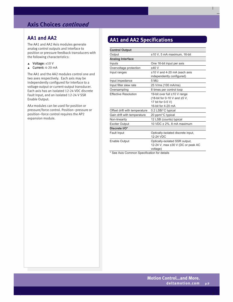
AA1 and AA2 The AA1 and AA2 Axis modules generate analog control outputs and interface to position or pressure feedback transducers with the following characteristics:
Voltage: ±10 V Current: 4-20 mA
The AA1 and the AA2 modules control one and two axes respectively. Each axis may be independently configured for interface to a voltage-output or current-output transducer. Each axis has an isolated 12-24 VDC discrete Fault Input, and an isolated 12-24 V SSR Enable Output.
AAx modules can be used for position or pressure/force control. Position–pressure or position–force control requires the AP2 expansion module.
AA1 and AA2 Specifications
Control Output Output ±10 V, 5 mA maximum, 16-bit Analog Interface Inputs One 16-bit input per axis Overvoltage protection ±40 V Input ranges ±10 V and 4-20 mA (each axis
independently configured) Input impedance 5 M Input filter slew rate 25 V/ms (100 mA/ms) Oversampling 8 times per control loop Effective Resolution 19-bit over full ±10 V range
(18-bit for 0-10 V and ±5 V, 17 bit for 0-5 V) 16-bit for 4-20 mA
Offset drift with temperature 0.2 LSB/ C typical Gain drift with temperature 20 ppm/ C typical Non-linearity 12 LSB (counts) typical Exciter Output 10 VDC ± 2%, 8 mA maximum Discrete I/O* Fault Input Optically-isolated discrete input,
12-24 VDC Enable Output Optically-isolated SSR output,
12-24 V, max ±30 V (DC or peak AC voltage)
* See Axis Common Specification for details

| Delta Computer Systems, Inc. | Battle Ground, WA USA 98604 | Tel: 360.254.8688 | Fax: 360.254.5435 | deltamotion.com |
p.10
Printed in USA 6/13
Axis Choices continued
MA1 and MA2 The MA1 and MA2 Axis modules generate analog control outputs and interface to position feedback transducers with the following characteristics:
Magnetostrictive Displacement Transducer (MDT): RS-422 Pulse Width Modulated (PWM) or Start/Stop, with programmable edge response
Synchronous Serial Interface (SSI): MDT, or single- or multi-turn absolute encoders with the SSI interface Note: Linear MDTs with SSI output should be of the synchronized type. Non-synchronized is not well-suited for motion control.
The MA1 and MA2 Axis modules control one and two axes respectively. Each axis has a 16-bit, ±10 V analog Control Output, an isolated 12-24 VDC discrete Fault Input, and an isolated 12-24 V SSR Enable Output. Each axis may be independently configured for interface to either an MDT or SSI transducer.
MAx modules can be used for position control. Position–pressure or position–force control requires the AP2 expansion module.
MA1 and MA2 Specifications
Control Output Output ±10 V, 5 mA maximum, 16-bit MDT Interface Transducer types MDT with Start/Stop or PWM
(Pulse Width Modulated) feedback Return input RS-422 differential Interrogation output RS-422 differential
(External interrogation transducers are required for motion control)
Resolution 0.0005” with 1 recirculation Recirculations Supports multiple recirculations only for
PWM transducers with internal recirculations.
Maximum transducer length 440” at 4ms (loop time dependent) Count rate 240 MHz SSI Interface Transducer types MDT, single-turn or multi-turn absolute
encoders Note: Linear MDTs with SSI output should be of the synchronized type. Non-synchronized is not well-suited for motion control.
Motion Type Linear or Rotary Data input RS-422 differential Clock output RS-422 differential Clock frequency 150 kHz, 250 kHz, or 375 kHz,
user-selectable Resolution Transducer dependent (typically down to
2 μm or approximately 0.00008” for MDTs)
Count encoding Binary or Gray Code Count data length 4 to 32 bits Discrete I/O* Fault Input Optically-isolated discrete input,
12-24 VDC Enable Output Optically-isolated SSR output,
12-24 V, max ±30 V (DC or peak AC voltage)
Cable Requirements Maximum SSI cable length
230-1000 ft (70-300 m) dependent on transducer and clock frequency
Cable type Twisted pair, shielded, low capacitance * See Axis Common Specification for details

Motion Control…and More. deltamotion.com
p.11
Axis Choices continued
QA1 and QA2 The QA1 and QA2 axis modules, with 5 V differential (RS-422) quadrature inputs and analog ±10 V control outputs, allow cost-effective control of a wide variety of electric drives as well as electric and hydraulic servo motors.
The QA1 and QA2 axis modules generate analog control outputs and interface to quadrature encoders with 5 V differential (RS-422) signals. Additional high-speed inputs allow for homing, registration, or positive and negative limits on a per axis basis.
The QA1 and the QA2 modules control one and two axes respectively. QAx modules can be used for position control. Position–pressure or position–force control requires the AP2 Expansion module.
Take advantage of the RMC70’s superior tuning and diagnostics by operating drives and amplifiers in their simplest mode, thereby transferring control to the RMC70. Doing this can lower long term maintenance costs by avoiding obsolescence issues common to many smart drives.
Cables
Cables for the QA modules are available for purchase from Delta. See page 19 for details.
QA1 and QA2 Specifications
Control Output Output ±10 V, 5 mA maximum, 16-bit Quadrature Interface (per Axis) Inputs per axis:
5 V differential (RS-422) receiver for A, B, and Z signals (Single-ended encoders are not supported due to low noise immunity)
Input impedance 215 Max Encoder Frequency 8,000,000 quadrature counts/second High-Speed Registration and Home Inputs High-Speed Inputs per axis:
1 Home Input 1 Registration X or Positive Limit Input 1 Registration Y or Negative Limit Input
Input “High” range 7 to 26.4 VDC (polarity independent), 3 mA maximum
Input “Low” range 0 to 3.5 VDC (polarity independent), <1 mA
Response Time 40 s General Discrete I/O* Fault Input Optically-isolated discrete input,
12-24 VDC Enable Output Optically-isolated SSR output,
12-24 V, max ±30 V (DC or peak AC voltage)
* See Axis Common Specification for details

| Delta Computer Systems, Inc. | Battle Ground, WA USA 98604 | Tel: 360.254.8688 | Fax: 360.254.5435 | deltamotion.com |
p.12
Printed in USA 6/13
Exp70 Expansion Modules For use with RMC70 Series Motion Controllers
Up to four Expansion modules (Exp70) can be added to an RMC70 motion controller to bring additional capabilities to the controller. The Exp70-A2 adds analog reference inputs, and the Exp70-AP2 adds analog inputs intended for use as pressure/force inputs as part of Delta’s powerful position–pressure/force control feature. The Exp70-D8 module adds discrete I/O functionality, and the Exp70-Q1 adds a ½–axis quadrature encoder input allowing multiple RMC70s to be electronically geared to a common master axis.
RMC70 Series motion controllers consist of a factory-configured Base module with one or two control axes, plus up to four field-installable Expansion modules. Each Expansion module can be added quickly by simply plugging it into an open expansion connector and securing it with four screws. No backplane is required—the first Expansion module plugs on to the right side of the Base module, and each subsequent Expansion module plugs into the previous Expansion module. Each Exp70 module has its own din-rail locking lever so the entire assembly can be securely mounted. The assembly may also be panel mounted.
Available Expansion Modules Order Number Features
EXP70-A2 Two ±10 V or 4-20 mA differential analog reference inputs. Inputs are 16 bit resolution, and are optically isolated from the controller.
EXP70-AP2
Two ±10 V or 4-20 mA differential analog inputs for use in position–pressure/force control axes. Inputs are 16 bit, and are optically isolated from the controller.
EXP70-D8
Eight discrete I/O individually configurable for any combination of inputs or outputs. Inputs and outputs are 12-24 VDC rated, polarity independent, and optically isolated from controller.
EXP70-Q1
One 5 V differential (RS-422) quadrature encoder input (A and B) with selectable termination. The RMC70 supports up to two Q1 modules.
Specifications Common to Expansion Modules
Mechanical Operating temperature +32 to +140 F (0 to +60 C) Storage temperature -40 to +185 F (-40 to +85 C) Agency compliance UL, CUL, CE Power Requirements All Expansion modules are powered from the RMC70

Motion Control…and More. deltamotion.com
p.13
Expansion Modules continued
Exp70-A2 Expansion Module The A2 module adds two analog reference inputs for position, velocity, pressure or force (single-input or dual-input differential) feedback. The A2 interfaces to transducers with the following characteristics:
Voltage: ±10 V Current: 4-20 mA
Each 16-bit input of the A2 can be individually configured to interface to voltage or current output
transducers.
The A2 generates a 10 VDC exciter output, which eliminates a precision power source in some potentiometer applications. This low noise reference also provides the accuracy benefits of ratiometric tracking.
Exp70-AP2 Expansion Module The AP2 module adds two analog inputs for pressure, force (single-input or dual-input differential), or acceleration feedback, and is required for control algorithms using two inputs, such as position–pressure, position––force, velocity––pressure, velocity––force, active damping, and acceleration control.
The AP2 interfaces to transducers with the
following characteristics:
Voltage: ±10 V Current: 4-20 mA
Each 16-bit input of the AP2 can be individually configured to interface to voltage or current output transducers.
The AP2 is required for dual-loop control, such as position–pressure or position–force.
A2 Specifications
Analog Interface Inputs Two 16-bit differential Isolation 500 VAC Overvoltage protection ±40 V Input ranges ±10 V and 4-20 mA (each channel
independently configured) Input impedance 5 M Input filter slew rate 25 V/ms Oversampling 8 times per control loop Effective Resolution 19-bit over full ±10 V range
(18-bit for 0-10 V and ±5 V, 17 bit for 0-5 V) 16-bit for 4-20 mA
Offset drift with temperature 0.2 LSB/ C typical Gain drift with temperature 20 ppm/ C typical Non-linearity 12 LSB (counts) typical over full 16-bit
range Exciter Output 10 VDC ± 2%, 8 mA
AP2 Specifications
Analog Interface Inputs Two 16-bit differential Isolation 500 VAC Overvoltage protection ±40 V Input ranges ±10 V and 4-20 mA (each channel
independently configured) Input impedance 5 M Input filter slew rate 25 V/ms Oversampling 8 times per control loop Effective Resolution 19-bit over full ±10 V range
(18-bit for 0-10V and ±5 V, 17 bit for 0-5 V) 16-bit for 4-20 mA
Offset drift with temperature 0.2 LSB/ C typical Gain drift with temperature 20 ppm/ C typical Non-linearity 12 LSB (counts) typical over full 16-bit
range

| Delta Computer Systems, Inc. | Battle Ground, WA USA 98604 | Tel: 360.254.8688 | Fax: 360.254.5435 | deltamotion.com |
p.14
Printed in USA 6/13
Expansion Modules continued
Exp70-D8 Expansion Module The D8 adds eight discrete inputs or outputs rated for 12-24 VDC. Up to 32 I/O may be added if all four Expansion modules are D8s.
Each I/O can be individually configured in software as an input or output. Inputs and outputs are polarity independent. However, since there is just one input common and one
output common, all inputs must be the same polarity, and all outputs must be the same polarity, but inputs need not be the same polarity as outputs. That is, outputs can switch high side or low side, and the inputs can be operated with either polarity signals.
Inputs and outputs are 12-24 VDC rated and optically isolated from the controller. Since all inputs share a common connection, there is no isolation between input points. Likewise, all outputs share a common pin and therefore do not have isolation between outputs.
The D8 can be used for the following purposes:
Control discrete outputs from User Programs
Control User Program flow based on discrete I/O state
Start User Program tasks based on discrete inputs
D8 Specifications
Discrete I/O Inputs and Outputs 8; each is individually configurable as an
input or output. Groups All inputs (up to 8) are in one group, and
all outputs (up to 8) are in one group. Each group shares a common pin.
Inputs Input type 12-24 VDC; sinking (sourcing driver) Logic polarity True “High” Isolation 500 VAC Input “High” range 7 to 26.4 VDC (polarity independent),
3 mA maximum Input “Low” range 0 to 3.5 VDC (polarity independent),
<1 mA Maximum propagation delay 100 μsec Outputs Output type Solid State Relay (SSR) Isolation 500 VAC Rated voltage 12-24 V, max ±30 V (DC or peak AC
voltage) Maximum current ±75 mA Maximum propagation delay 1.5 ms Logic 1 (True, On) Low impedance (50 maximum) Logic 0 (False, Off) High impedance (<1 A leakage current
at 250 V)

Motion Control…and More. deltamotion.com
p.15
Expansion Modules continued
Exp70-Q1 Expansion Module The Q1 module adds one 5V differential (RS-422) quadrature encoder reference input for position feedback. Inputs include quadrature A and B, plus one 12-24 VDC high-speed registration input.
The A and B inputs have selectable termination allowing up to 32 Exp70-Q1 modules to be daisy-chained with only the last input terminated. This
allows up to 64 slave axes to be electronically geared to one master quadrature signal.
Q1 Specifications
Quadrature Encoder Interface Inputs 5 V RS-422 differential receiver
Quadrature A, B (Single-ended encoders are not supported due to low noise immunity)
Input Impedance 16 k unterminated 215 terminated (selectable by jumpers)
Max Encoder Frequency 8,000,000 quadrature counts/sec Daisy-Chaining Daisy-chain one encoder to a maximum
of 32 Q1 modules High-Speed Registration Input Input “High” range 7 to 26.4 VDC (polarity independent),
3mA maximum Input “Low” range 0 to 3.5 VDC (polarity independent),
<1 mA Reg Input Response Time 40 sec

| Delta Computer Systems, Inc. | Battle Ground, WA USA 98604 | Tel: 360.254.8688 | Fax: 360.254.5435 | deltamotion.com |
p.16
Printed in USA 6/13
RMC70 Series Wiring Note: For detailed wiring diagrams, see the RMC70 Startup Guide or the RMCTools help.
RMC75E CPU Module
Ethernet (RJ-45) Twisted pair cable CAT5, CAT5e or CAT6, UTP or STP conforming to IEEE 802.3 for 100BASE-T must be used.
Power Terminal Block Pin Label Function 1 +24Vdc PS +24 VDC power 2 PS Return Isolated power common 3 Case Chassis ground
Monitor Port (USB “B” Connector) Accepts a standard USB cable to communicate with a PC running RMCTools.
RMC75P CPU Module
PROFIBUS-DP Standard PROFIBUS-DP cabling must be used.
Power Terminal Block Pin Label Function 1 +24Vdc PS +24 VDC power 2 PS Return Isolated power common 3 Case Chassis ground
Monitor Port Accepts a null-modem DB-9 female-to-female cable to communicate with a PC running RMCTools.
RMC75S CPU Module
RS-232 (DB-9) Pin Function 2 Received data 3 Transmitted data 5 Serial common 7 Request to Send (RTS) 8 Clear to Send (CTS)
RS-485 Terminal Block Pin Label Function 1 + T/R Tx/ Rx B (+) 2 Trm Jpr Jumper to +T/R for termination 3 - T/R Tx/ Rx A (-) 4 SCmn Isolated serial common 5 Bias Jumper Jumper to SCmn for bias 6 Case Chassis ground
Power (shared connector with RS-485) Pin Label Function 6 Case Chassis ground 7 +24Vdc PS +24 VDC power 8 PS Return Isolated power common
Monitor Port Accepts a null-modem DB-9 female-to-female cable to communicate with a PC running RMCTools.
MAx Axis Module
One connector per axis: Pin Label Function 1 + Fault In
Fault Input (12-24 VDC) 2 - Fault In 3 + Enable Out
Enable Output (12-24 VDC) 4 - Enable Out 5 Control Out
Control Output (±10 V) 6 Common MDT SSI 7 + Int/Clock + Interrogate + Clock 8 - Int/Clock - Interrogate - Clock 9 Common Common Common 10 + Ret/Data + Return + Data 11 - Ret/Data - Return - Data 12 Case Chassis ground
Note: Pins 6 and 9 are electrically the same.
AAx Axis Module
One connector per axis: Pin Label Function 1 + Fault In
Fault Input (12-24 VDC) 2 - Fault In 3 + Enable Out
Enable Output (12-24 VDC) 4 - Enable Out 5 Control Out
Control Output (±10 V) 6 Common 7 + Anlg In
Analog input (For 4-20 mA, jumper pins 7 and 8)
8 Jmpr for 4- 20mA
9 - Anlg In 10 Common Analog common
11 + 10Vdc Exciter
Exciter output for use with potentiometers
12 Case Chassis ground Note: Pins 6 and 10 are electrically the same.

Motion Control…and More. deltamotion.com
p.17
Wiring continued Note: For detailed wiring diagrams, see the RMC70 Startup Guide or the RMCTools help.
QAx Axis Module
One connector per axis: Pin Label Function 1 A- A- from encoder (5 V signal) 2 A+ A+ from encoder (5 V signal) 3 B- B- from encoder (5 V signal) 4 B+ B+ from encoder (5 V signal) 5 n/c No connection 6 RegY/NegLim- Registration Y or
Negative Limit (12-24 VDC) 7 RegY/NegLim+ 8 RegX/PosLim- Registration X or
Positive Limit (12-24 VDC) 9 RegX/PosLim+ 10 n/c No connection 11 n/c No connection 12 Control Out
Control Output (±10 V) 13 Common 14 Z- Index pulse from encoder
(5 V signals) 15 Z+ 16 Cmn Common 17 n/c No connection 18 Home-
Home Input (12-24 VDC) 19 Home+ 20 - Fault In
Fault Input (12-24 VDC) 21 + Fault In 22 n/c No connection 23 n/c No connection 24 - Enable Out
Enable Output 25 + Enable Out
Note: Pins 13 and 16 are electrically the same.
Exp70-A2 Expansion Module
Pin Label Function 1 10V Exciter+ Exciter output for use with
potentiometers 2 Anlg Cmn Isolated analog common 3 Input 0+ Analog input 0
(For 4-20mA, jumper pins 3 and 4)
4 Jumper for 4-20mA
5 Input 0- 6 Anlg Cmn Isolated analog common 7 Input 1+ Analog input 1
(For 4-20mA, jumper pins 7 and 8)
8 Jumper for 4-20mA
9 Input 1- 10 Case Chassis Ground
Note: Pins 2 and 6 are electrically the same.
Exp70-AP2 Expansion Module
Pin Label Function 1 Input 0+
Analog input 0 (For 4-20 mA, jumper pins 1 and 2)
2 Jumper for 4-20mA
3 Input 0- 4 Anlg Cmn Isolated analog common 5 Input 1+
Analog input 1 (For 4-20 mA, jumper pins 5 and 6)
6 Jumper for 4-20mA
7 Input 1- 8 Case Chassis ground
Exp70-D8 Expansion Module
Pin Label Function 1 Output Cmn Common to one side of all
outputs 2 I/O 0 Input or output 0 3 I/O 1 Input or output 1 4 I/O 2 Input or output 2 5 I/O 3 Input or output 3 6 I/O 4 Input or output 4 7 I/O 5 Input or output 5 8 I/O 6 Input or output 6 9 I/O 7 Input or output 7 10 Input Cmn Common to one side of all
inputs
Exp70-Q1 Expansion Module
Pin Label Function 1 Reg In+ High-speed registration or
home input 2 Reg In- 3 A+
Encoder A Input (to enable termination, jumper pins 3 and 4*)
4 Jumper for Termination*
5 A- 6 Cmn Common 7 B+
Encoder B Input (to enable termination, jumper pins 7 and 8*)
8 Jumper for Termination*
9 B- 10 Case Chassis ground
* Use either both jumpers or no jumpers.

| Delta Computer Systems, Inc. | Battle Ground, WA USA 98604 | Tel: 360.254.8688 | Fax: 360.254.5435 | deltamotion.com |
p.18
Printed in USA 6/13
Drawings are not at 1:1 scale.
RMC70 Series Dimensions
RMC70 Base Module Series Mounting Dimensions
D8 Mounting Dimensions
AP2, A2, Q1 Mounting Dimensions
Motion Control…and More. deltamotion.com
p.19
Accessories
Voltage-to-Current Converters
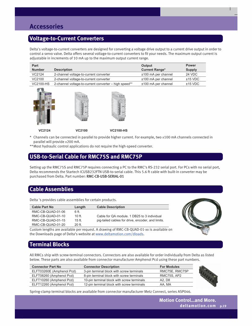
Delta's voltage-to-current converters are designed for converting a voltage drive output to a current drive output in order to control a servo valve. Delta offers several voltage-to-current converters to fit your needs. The maximum output current is adjustable in increments of 10 mA up to the maximum output current range.
Part Number Description
Output Current Range*
Power Supply
VC2124 2-channel voltage-to-current converter ±100 mA per channel 24 VDC VC2100 2-channel voltage-to-current converter ±100 mA per channel ±15 VDC VC2100-HS 2-channel voltage-to-current converter – high speed** ±100 mA per channel ±15 VDC
VC2124 VC2100 VC2100-HS
* Channels can be connected in parallel to provide higher current. For example, two ±100 mA channels connected in parallel will provide ±200 mA.
** Most hydraulic control applications do not require the high-speed converter.
USB-to-Serial Cable for RMC75S and RMC75P
Setting up the RMC75S and RMC75P requires connecting a PC to the RMC’s RS-232 serial port. For PCs with no serial port, Delta recommends the Startech ICUSB232FTN USB-to-serial cable. This 5.6 ft cable with built-in converter may be purchased from Delta. Part number: RMC-CB-USB-SERIAL-01
Cable Assemblies
Delta 's provides cable assemblies for certain products.
Cable Part No Length Cable Description RMC-CB-QUAD-01-06 RMC-CB-QUAD-01-10 RMC-CB-QUAD-01-15 RMC-CB-QUAD-01-20
6 ft. 10 ft. 15 ft. 20 ft.
Cable for QA module. 1 DB25 to 3 individual pig-tailed cables for drive, encoder, and limits.
Custom lengths are available per request. A drawing of RMC-CB-QUAD-01-xx is available on the Downloads page of Delta’s website at www.deltamotion.com/dloads.
Terminal Blocks
All RMCs ship with screw-terminal connectors. Connectors are also available for order individually from Delta as listed below. These parts are also available from connector manufacturer Amphenol Pcd using these part numbers.
Connector Part No Connector Description For Modules ELFT03260E (Amphenol Pcd) 3-pin terminal block with screw terminals RMC75E, RMC75P ELFT08260 (Amphenol Pcd) 8-pin terminal block with screw terminals RMC75S, AP2 ELFT10260 (Amphenol Pcd) 10-pin terminal block with screw terminals A2, D8 ELFT12260 (Amphenol Pcd) 12-pin terminal block with screw terminals AA, MA
Spring-clamp terminal blocks are available from connector manufacturer Metz Connect, series ASP046.

| Delta Computer Systems, Inc. | Battle Ground, WA USA 98604 | Tel: 360.254.8688 | Fax: 360.254.5435 | deltamotion.com |
p.20
Printed in USA 6/13
The RMC Family of Motion Control
Connect. Control. Optimize.