the road to imt-advanced communication systems: state-of
TRANSCRIPT

The Road to IMT-Advanced
Communication Systems: State-of-the-Art
and Innovation Areas Addressed by the
WINNER+ Project
Afif Osseiran1, Eric Hardouin
2, Mauro Boldi
3, Ivan Cosovic
4, Karine Gosse
5, Alexandre Gouraud
2,
Jijun Luo6, Jose F. Monserrat
7, Tommy Svensson
8, Antti Tölli
9, Albena Mihovska
10, Simone
Redana6, Marc Werner
11 and Werner Mohr
6
1Ericsson AB, SE-164 80, Stockholm, Sweden
2Orange Labs, France
3Telecom Italia, Turin, Italy
4DOCOMO Euro-Labs, Munich, Germany
5Was with Motorola Labs, France
6Nokia Siemens Networks, Munich, Germany
7Polytechnic University of Valencia - iTEAM, Spain
8Chalmers University of Technology, Signals and Systems, Göteborg, SE-412 96, Sweden
9Centre for Wireless Communications, University of Oulu, Finland
10 CTIF, Aalborg University, Denmark
11Qualcomm, Germany

Abstract: The WINNER project phases I and II contributed to the
development, integration and assessment of new mobile networks techniques
from 2004 to 2007. Some of these techniques are now in the 3GPP LTE and
IEEE 802.16 (WiMAX) standards, while others are under consideration for
LTE-Advanced and 802.16m. The WINNER+ project continues this forward-
looking work for IMT-Advanced technologies and their evolutions, with a
particular focus on 3GPP LTE-Advanced. This article provides an overview of
the WINNER system concept and several of its key innovative components.
Keywords: Advanced Antennas, Advanced RRM, Coordinated Multi-Point systems,
Flexible Spectrum Use, LTE, IMT-Advanced, Network Coding, OFDMA, Peer-to-
Peer, Relaying.
1. Introduction
The race towards International Mobile Telecommunications (IMT)-Advanced radio access
technologies was officially started in March 2008, when the ITU Circular Letter was sent out to
invite technology proposals submissions [1]. In IEEE 802 standards, the work on IMT-Advanced
already started in 2007, and the requirements for the targeted interface, the IEEE 802.16m, were
completed at the end of 2007. The Long Term Evolution (LTE)-Advanced Study Item was launched
by 3GPP in May 2008.
The WINNER (Wireless World Initiative New Radio) project Phase I and Phase II [2] was a major
EU-funded initiative joining the effort of major industrial and academic players in mobile
communications. Its main outcomes were the definition of an innovative high-performance system
concept and the related system design, backed up by a proof-of-concept in the form of performance
assessments in realistic system deployments [3] [4][5]. The CELTIC WINNER+ project continues
this forward-looking work in order to contribute to the definition of the IMT-Advanced (IMT-A)
technology proposals and their evolutions, in particular, the 3GPP LTE-Advanced (LTE-A) [6]. The
core activity of the project is the development of innovative techniques integrated with the overall

system functionalities, whose benefits are demonstrated by meaningful end-to-end performance
assessments.
The basis of the WINNER+ concept is the current LTE Release 8 (R8) standard, enhanced by
selected features from WINNER-II. Therefore, its basic characteristics can be outlined from the
commonalities between both WINNER-II and LTE R8 systems. Indeed, a close link exists between
the WINNER-II concept and the 3GPP LTE technology. Both were developed simultaneously, and
many major contributors to 3GPP were also members of the WINNER-II consortium. It was,
therefore, natural to observe a certain convergence between the technological choices of both
concepts, particularly for the physical layer, while the consensus on the performance of the different
techniques was being established. The WINNER project time plan compared to 3GPP and ITU
activities is shown in Figure 1.
Figure 1: WINNER+ timeline compared to 3GPP and ITU activities.
In LTE Release 8, the Radio Access Network (RAN) is only composed of Base Stations (BSs called
also eNodeBs) providing the user plane and control plane protocol terminations towards the user
equipment (UE) [7]. The BSs are inter-connected and directly linked to a gateway providing
connection to other IP-based networks. This so-called flat architecture simplifies the user data flow
and allows flexible and cost-effective capacity scaling.
The multiple-access scheme in the downlink is based on Orthogonal Frequency Division
Multiplexing (OFDM) with cyclic prefix. The uplink scheme is based on single-carrier frequency
2007 2008 2009 2010 2011
LTE CR phase
LTE-Advanced SI Work Item
Proposal
Evaluation
Specification
LTE
WINNER II WINNER+ Research
Standardization
Regulation (IMT-Advanced)
Deployment

division multiple access (SC-FDMA), having a low peak to average power ratio that facilitates UE
design.
The LTE radio bandwidth is scalable, ranging from 1.4 MHz to 20 MHz. FDD (Frequency Division
Duplex) and TDD (Time Division Duplex) modes are supported. The FDD mode enables half and
full duplex from the UE point of view.
Cross-Layer mechanisms such as link adaptation and hybrid automatic repeat request (HARQ) with
soft combining ensure efficient use of the time-frequency resources. The transmit time interval is
short (1 millisecond) for low latency and to allow the system to take advantage of multi-user
diversity via time and frequency adaptive scheduling.
Multi-antenna support is a key feature for link robustness and high average user throughputs: two to
four transmit antennas can be used for transmit diversity and codebook-based linear precoding. The
designed system allows up to four spatial layers for single-user Multiple-Input Multiple-Output
(MIMO) transmission. Multi-User MIMO in both uplink and downlink are also available
mechanisms for improving the cell capacity. More detailed information about LTE can be found in
[8].
This article provides an overview of the WINNER+ system concept and several of its key
innovative components. The key innovative components from WINNER-II are summarized in
Section 2. Section 3 presents the innovation areas targeted by WINNER+. Finally Section 4
concludes the paper.
2. Key Features of the WINNER-II System Concept
The WINNER-II system concept [3][5] was designed as a user centric system with the goal to meet
the IMT-A requirements. Beyond the common basis with LTE Release 8 and the support of wider
bandwidths (up to 100 MHz in total, shared between uplink and downlink), new ideas and
techniques were proposed, in particular in the areas of multiple access, Medium Access Control
(MAC) layer and advanced antennas, relaying, and spectrum functionalities. These ideas are
discussed in the following. Some of them can be integrated directly into the current LTE standard,

while others might require some changes in the specifications. The key features of WINNER-II
along with LTE Release 8 and LTE-A are summarized in Table 1.
Table 1 Key Features of LTE, WINNER-II and LTE-A
3GPP LTE WINNER-II1 3GPP LTE-A
Max. Peak Data Rate (Mbps)
300 1000 1000
Channel Bandwidth (MHz)
1.4 to 20 1.25 to 100 1.4 to 100
Spectrum Band (GHz)
0.7 to 2.6 2 to 6 0.45 to 4.99
Access method
OFDMA SC-FDMA
flexible OFDMA SC-FDMA
Duplex mode FDD, TDD FDD, TDD FDD, TDD
Relaying not integrated
integrated under study
Domain Wide Area Metropolitan Area, Local
Area
Wide Area, Metropolitan
Area, Local Area
Wide Area, Metropolitan
Area, Local Area
2.1 Multiple Access, Medium Access Control and Advanced Antennas
The WINNER MAC layer is designed for minimum delays2 of 1 millisecond in the downlink and 2
milliseconds in the uplink, which is attained for single hop transmission by a combination of short
frame durations and tight feedback control loops. This low latency enables adaptability with respect
to fast channel variations, so that link adaptation and multi-user scheduling gains can boost spectral
efficiency. It also enables fast link retransmissions with HARQ (Hybrid Automatic Repeat-reQuest)
which facilitates high-throughput TCP/IP traffic and provides reliable links even for real-time
services.
The OFDM Access (OFDMA) based multiple access concept is highly flexible and can be deployed
in a wide variety of system bandwidths and propagation scenarios. For good channel conditions
and/or low user velocities, accurate channel state information (CSI) can be obtained. In these cases,
the resource allocation is based on frequency-adaptive transmission with adaptive TDMA/OFDMA,
which enables increased spectrally efficient transmission through multi-user scheduling and
1 WINNER-II is shown for comparison purposes. In practice, WINNER+ will not be a competing technology with regard
to IMT-A.
2 Delay from the MAC Layer of the source to the MAC layer of the destination.

individual link adaptation of time-frequency-space resources. The downlink signaling overhead is
reduced by an adaptive hierarchical design of the allocation tables containing the resource
assignment description. The short frame duration in combination with channel prediction enables
frequency-adaptive transmission even at vehicular speeds. The frequency-adaptive transmission
scheme adapts the modulation individually for each chunk (set of contiguous OFDM subcarriers),
while the same code rate is applied to all the chunks of a given user. The associated bit-loading
algorithm [9] is based on the mutual information per coded bit and allows for combining fine-
grained adaptation with an efficient Bit-Interleaved Coded Modulation (BICM) scheme based on
Quasi-Cyclic Block Low-Density Parity Check (QC-BLDPC) channel coding for arbitrary
codeword lengths. Even without employing power loading, this scheme yields a performance that is
very close to the theoretical optimum.
A robust diversity-based transmission scheme is also needed for users with high speed or low data
rate and for short control packets. The multiple-access scheme for these scenarios is based on a
highly flexible non-frequency-adaptive transmission mode. The scheme obtains its robustness by
means of a dispersed allocation of multiple blocks in frequency, each block consisting of a few
consecutive subcarriers in a few consecutive OFDM symbols. This resource allocation structure
enables a tunable degree of frequency diversity and low allocation signaling overhead. Moreover, it
provides support for high power amplifier efficiency in the uplink by the use of a Discrete Fourier
Transform (DFT) precoding step. At last, the possibility of a sub-slot allocation enables robust and
efficient transmission also for small packets and, at the same time, improved battery life in UEs.
The uplink scheme denoted Block Interleaved Frequency Division Multiple Access (B-IFDMA) [3]
[5] is a generalization of the LTE SC-FDMA scheme.
An important enabler for efficient co-existence and switching of frequency-adaptive and non-
frequency-adaptive transmission modes is the cross-layer design of the MAC layer. Efficient
switching between the two modes is supported by a common approach for channel coding and
retransmission with hop-by-hop HARQ. WINNER-II uses advanced Type-II incremental

redundancy HARQ. The single low rate mother code is punctured to obtain multiple higher coding
rates (rate-compatible punctured code) [3][5].
The flexible WINNER-II advanced antennas concept [10] works with varying degrees of CSI at the
transmitter and is able to foster flexible combinations of spatial multiplexing, Space Division
Multiple Access (SDMA), spatial diversity and beamforming, and means for enhanced interference
management. The transmitter is illustrated in Figure 2. Not all of these function blocks are
operative all the time. Their use depends on the scenario, system load, propagation conditions,
number of receivers (unicast, multicast or broadcast) and the corresponding desired multi-antenna
processing gain (multiplexing, diversity and directivity).
segmentation
MUX
FEC FEC
MOD MOD
LDC LDC
segmentation
FEC FEC FEC
segmentation
FEC FEC FEC
MOD MOD
LDC LDC
chunk layers
transport block ktransport block 1 transport block K
modulated chunk layers
virtual antenna chunks
FEC blocks (or encoded segments of transport blocks)
LPLP
GMC
Antenna summation
chunk 1 chunk c chunk C
Assembly of chunks to raw symbol data
IFFT
CP
IFFT per antenna
CP extension
To RF
FEC
segments of transport blocks
ResourceScheduler .
.
Time
CQI, CSI
CQI errorsNon-frequency adaptive
- Link
Frequency adaptiveBuffer levels
Map on dispersed chunks Map on optimal chunksPacketprocessing
segmentation
MUX
FEC FEC
MOD MOD
LDC LDC
segmentation
FEC FEC FEC
segmentation
FEC FEC FEC
MOD MOD
LDC LDC
chunk layers
transport block ktransport block 1 transport block K
modulated chunk layers
virtual antenna chunks
FEC blocks (or encoded segments of transport blocks)
LPLP
GMC
Antenna summation
chunk 1 chunk c chunk C
Assembly of chunks to raw symbol data
IFFT
CP
IFFT per antenna
CP extension
To RF
FEC
segments of transport blocks
ResourceScheduler .
.
Time
CQI, CSI
CQI errorsNon-frequency adaptive
- Link
Frequency adaptiveBuffer levels
Map on dispersed chunks Map on optimal chunksPacketprocessing
Figure 2: The WINNER transmitter.
Optional DFT precoding

Further advanced Multi-User Multiple-Input Multiple-Output (MU-MIMO) precoding schemes,
such as successive minimum mean square error, were proposed. These techniques multiplex streams
to several users in order to provide very high performance gain. The gain is especially pronounced
in a rich scattering radio environment (i.e. local area), where distributed antennas achieve a spectral
efficiency of more than 13 bps/Hz [10].
2.2 Relaying
Advanced relaying techniques are considered as an attractive solution to enhance coverage and/or
capacity in specific locations [11][12]. Important characteristics of these new network nodes are
ease of deployment (due to in-band backhauling) and reduced deployment cost compared to a
regular base station (due to lower site costs) [13].
The Relay Node (RN) has been embedded in WINNER-II as an integral part of the system concept
[4]. The same air-interface is used for connecting the UE to the eNodeB (eNB) or RN and the RN to
its serving eNB. Figure 3 shows the basic elements of a multi-hop connection. The UE is always
connected to an eNB or RN via an access link. The relay link is between an eNB and a RN or two
RNs, where multi-hop link is comprised of at least one relay link and an access link. In a multi-hop
scenario the eNB forms together with its served RNs a Relay Enhanced Cell (REC).
UE
UE
RN
eNB
access link
relay link
access lin
k
multi-hop link
UE
UE
RN
eNB
access link
relay link
access lin
k
multi-hop link
Figure 3: Relay scenario as investigated by WINNER-II.
The introduction of relays in cellular communication systems entails a large number of deployment
options to be investigated; in particular the layout of a REC depends on the number of hops, the

number of RNs served by one eNB, the positioning of the RN, the transmit power of an RN, the
spatial temporal processing, and the radio environment (LOS / NLOS probabilities).
Therefore, a multitude of deployments may be envisioned and different deployments are expected to
be suitable for different scenarios.
The relaying concept was designed in WINNER-II under the following baseline assumptions:
• layer 2 (decode and forward) relays;
• optimization of the system for two hops, but no restriction on the number of hops;
• tree-based topology (not mesh) to avoid complex routing schemes;
• no additional overhead to cells that do not use relays;
• support of cooperative relaying as an additional feature to increase capacity.
The performance of relays depends on the level of integration of the relaying concept into the
protocol and system architecture. Firstly, it is necessary to integrate the RN as part of the end-to-end
multi-hop link between the UE and the RAN. This comprises user-plane and control-plane functions
and protocols. In WINNER-II, one design goal was to provide the UE with a unique interface no
matter whether it is connected to an eNB or a RN. Secondly, the RN has to be integrated into the
RAN, which requires control plane functions, mainly to allow relay enhanced radio resource
management.
The integration of the RN to the control plane of the WINNER-II system is depicted in Figure 4.
The network layer control plane signaling is handled by the Radio Resource Control (RRC)
protocol. The control and configuration of the RN is performed by the sub layer RRC2. The RRC
at the eNB terminates the protocols initiated at both the RN and the UE. More details about
the relaying concept designed by WINNER-II can be found in [3] [4][5].

RRC
RLC
MAC
PHY
RRC
RLC
MAC
PHY
RRC2
RLC
MAC
PHY
RRC2
Transport
Network
Transport
Network
UE RN eNB
Gateway
RRC
RLC
MAC
PHY
RRC
RLC
MAC
PHY
RRC2
RLC
MAC
PHY
RRC2
Transport
Network
Transport
Network
UE RN eNB
Gateway
Figure 4: Control plane of the WINNER-II architecture enhanced by RN.
2.3 Spectrum Functionalities
A conceptual overview of the spectrum control functions was presented in the WINNER-II system
concept description [3]. The most salient spectrum control functions are summarized in Table 2.
Inter-Radio Access Technology (RAT) flexible spectrum use (FSU) and intra-WINNER FSU are
distinguished. The WINNER-II system is understood to function under an IMT-A system (i.e. LTE-
A system). The underlying FSU functions allocate spectrum resources to the IMT-A system or
coordinate the spectrum access between IMT-Advanced system and other systems.
Table 2: Spectrum functionality classification
Inter RAT FSU Intra-WINNER FSU
Spectrum sharing functions Spectrum assignment functions
This group includes: • Vertical Sharing 1 (VS1) • Vertical Sharing 2 (VS2) • Horizontal Sharing with Coordination (HwC) • Horizontal Sharing without coordination (HwoC)
This group includes: • Long Term Assignment (LT) • Short Term Assignment (ST)
Under the spectrum sharing (inter RAT FSU) umbrella, four different schemes have been
developed. They are based on the access rights of each system to the shared spectrum. If one system
has a priority access to the spectrum over the other, then vertical sharing schemes are applied. In
such a case, if the WINNER system is the primary system, then a scheme called Vertical Sharing 1

(VS1) is used. If the WINNER system is a secondary system and has higher priority access rights
compared to any other secondary system, then a scheme called Vertical Sharing 2 (VS2) is applied.
For instance, an IMT A system can co-exist with the Fixed Satellite system where the later functions
as a primary system under the VS2 category. In this scenario, the IMT A system may adopt a
dynamic and opportunistic use of the unused part of the spectrum with good knowledge about the
deployed FSS system. The situation where WINNER and another system have the same access
rights to the spectrum results in horizontal sharing, which involves two different sharing schemes.
The first horizontal sharing scheme assumes that the systems contending for spectrum can
coordinate with each other to enable efficient spectrum allocation. This is called Horizontal Sharing
with Coordination (HwC). The second scheme is considered when both systems do not coordinate
with each other in the framework of spectrum sharing functionalities. This scheme is called
Horizontal Sharing without Coordination (HwoC).
Once the spectrum is allocated to the WINNER system, its allocation within the WINNER RANs
(e.g. belonging to different operators) is determined by the spectrum assignment scheme. WINNER
considers Long Term (LT) and Short Term (ST) spectrum assignment strategies to take advantage
of the changing nature of the spectrum availability and the traffic demand in different parts of a
multi-operator environment. The LT scheme assigns the spectrum at a higher level of geographical
granularity between multiple RANs. During the LT assignment functional procedure, the spectrum
is negotiated over a long time scale, i.e., in the order of tens of minutes, over the WINNER
operational deployment. The ST assignment acquires the fine tuning of the spectrum assignment at
the cell level. This is performed at shorter time scales than in LT assignment: the ST assignment
negotiation of spectrum is performed over time periods of several hundreds of milliseconds. The ST
functions shall be preferably located at the lower layers and near to the radio front. On the other
hand the LT functions shall be at the higher layers and close to the core network. For instance, the
ST spectrum assignment function can be allocated at the LTE-A eNB (if such approach was
considered for LTE-A). The long term assignment function with more LTE-A eNBs involvement
can be allocated either in control plane GW or Operations & Maintenance (O&M) server. However,
due to large difference among different IMT-A deployment modes, namely from local area to wide

area, the functional allocation to the logical entities in IMT-A systems must be designed case by
case.
3. New Areas of Innovation in WINNER+
The pioneer system integration of innovative techniques performed in WINNER-I and WINNER-II
is being continued in WINNER+ to assist the development of highly competitive IMT-A air
interfaces, and especially the LTE-Advanced. Four key innovation areas are addressed:
• Advanced Radio Resource Management (RRM) deals in particular with radio resource
allocation (scheduling), Self-Optimized Networks (SON), and efficient Multicast/Broadcast
services;
• Spectrum technologies aim at defining preferred spectrum usage scenarios based on the
outcomes of the World Radiocommunication Conference (WRC)'07, and at investigating
spectrum sharing issues;
• Peer-to-peer and Network Coding study the enhancement of cellular networks performance
through device-to-device communications and related cooperation schemes, together with
network coding techniques;
• Advanced Multiple Antenna Systems involve two main tracks: the optimization of system
aspects related to multiple antenna schemes and the coordination of transmissions and/or
reception from remote antennas to further enhance the system performance.
The remainder of this section outlines the main challenges of the above mentioned innovations.
3.1 Advanced Radio Resource Management
The concept of RRM has become a key element of current and future wireless and wired
communication networks to provide the negotiated Quality of Service (QoS) to the end users. The
efficiency of RRM techniques has a direct impact on each user’s individual performance and,
furthermore, on the overall network performance and operational expenditures (OPEX). In
consequence, these techniques have to make the most of the available resources for the benefit of
users and operators.

According to the ITU-R requirements, IMT-A systems must enable Advanced Radio Resource
Management (ARRM) techniques by gathering different kind of statistics, which include system and
user parameters. Therefore, it is of paramount importance not only to devise new ARRM
mechanisms but also to assess the signaling requirements of each proposal. These new ARRM
mechanisms should address three important challenges: (1) maximize the system flexibility in
resource allocation, both in uplink and downlink, (2) support advanced and distributed interference
mitigation schemes and (3) take advantage of Enhanced Multicast Broadcast Services.
Concerning the first challenge, the complexity of an OFDMA system, encompassing the time,
frequency and space dimensions requires the design of optimum dynamic resource allocation
algorithms that allow extending the opportunistic scheduling concept to all dimensions. Within the
WINNER+ project, several schedulers are proposed that include all dimensions and the fulfilling of
user QoS requirements. At the same time, the allocated power must be controlled to reduce
interference as much as possible.
Secondly, load and call admission control manages the access to the network and plays a major role
in the avoidance of system congestion. The WINNER+ system adopted a combined centralized and
distributed approach to the execution of load and admission control and in support of user mobility.
This shortens the time for serving the users and provides the benefits of a centralized control in
situations of medium to high network loads.
Another key aspect for innovation in interference mitigation is the concept of self-organization.
Self-organization allows the network to detect changes, make intelligent decisions based upon these
inputs, and then implement the appropriate action. The system must be situation-aware, and must
take advantage of this information to dynamically configure itself in a distributed fashion. Applied
to RRM, SON allows, for example, making a dynamic and automatic optimum coordination of the
radio resource utilization at the cell edge, in order to reduce interference and avoid performance loss
or service degradation.
Concerning the last challenge, two scenarios of broadcast networking are considered in WINNER+:
the Multi-Frequency Networking (MFN) and the Single Frequency Networking (SFN). The results

indicate the clear advantage of SFN, which allows the signal transmitted form neighboring cells to
be turned into useful signal. Therefore, SFN retains limited receiver complexity and resource usage
in terms of allocated sub-carriers. Besides, optimum switching criteria between broadcast and
unicast service are envisaged in order to increase the system efficiency.
3.2 Flexible Spectrum Use
To support demands of future wireless systems for high data rates and large user capacities, efficient
use of the available spectrum resources is of great importance. Spectrum scarcity and bandwidth
fragmentation lead the actual demand for transmission resources to often exceed the available
bandwidth. Dynamic spectrum sharing and FSU are promising technologies to overcome this
problem.
At the WRC’07 the new spectrum bands for IMT systems were identified [14]. The new spectrum
allocated for mobile communications does not fully correspond to what was required for IMT-A
systems. Therefore, the mobile operators in some countries might be forced to aggregate spectrum
of two or more separated sub-bands for down- and uplink bands. The separated regions’ bands can
be situated in the same frequency band (e.g. in the 3.5 GHz band) or in separated bands (e.g. part in
the 2 GHz band and part in the 3.5 GHz band). Some of the main open questions related to spectrum
aggregation concern the maximum acceptable frequency distance and the maximum acceptable
number of fragmented bands that are aggregated at the receiver. Also, the physical and hardware
origins of these constraints need to be established.
Technology-neutral spectrum allocation and spectrum liberalization give freedom to the spectrum
holders to change the use of their spectrum, e.g. by migrating spectrum used for 2G and 3G systems
toward IMT-A systems, or to lease or even to sell spectrum on secondary spectrum markets. A
related issue is the population of the spectrum made vacant by the switch of analogue terrestrial TV
broadcasting in the frequency band 470 - 862 MHz to digital TV. Since processing of digital data
enables a more efficient use in terms of required bandwidth, a considerable amount of frequency
spectrum can be released from broadcasting use, leading to the digital dividend approach which
allows launching IMT commercial systems in this band.

Self-organized networks in which coordination among wireless network entities is limited or even
non-existent are one of the key components in the future wireless systems. For example, femto-cells
are self-configurable miniature home BSs that are deployed in operator-owned spectrum and are
based on the same cellular standards as macro-cells. Due to the foreseen mass deployment, neither
full coordination by a macro-cell, nor control via a centralized maintainer is possible. Femto-cells
dynamically share operator’s spectrum not only among themselves, but also with macro-cells
resulting in an intra-operator FSU scenario. Femto-cell BSs and femto-cell UEs cause interference
on macro-cell BSs and macro-cell UEs, and vice versa. Thus, interference due to the femto-cells
deployment in the same band where macro-cells already operate is a major concern and dynamic
spectrum sensing and resource negotiation among cells are envisioned for efficient spectrum use.
3.3 Peer-to-Peer and Network Coding
Future wireless systems will be characterized by a need for large user capacity and high reliability.
Yet, the inherent fading and interference of wireless communications render these design objectives
challenging. There are currently many diversity techniques proposed to combat fading, i.e. MIMO
for space diversity, channel coding for time diversity, OFDM etc. However, the applications of
these techniques are limited by hardware complexity, size, delay and bandwidth.
A promising alternative is to design the system from an overall network capacity point of view, i.e.
network information theory. In this context, device-to-device communications, in other words peer-
to-peer (P2P) radio communications, become a key feature to be supported by next generation
wireless designs. The advantages are manifold: offloading the cellular system, reducing battery
consumption, increasing bit-rate, robustness to infrastructure failures, etc. Thus, the design of an
efficient device-to-device communication mode, with minimal interference to the cellular overlay
network and maximum capacity, is definitely a key challenge to overcome.
In the emerging cellular deployment concepts with multi-hop communications relayed by fixed or
mobile entities (infrastructure cooperative relaying, device-to-device communications and
cooperation), a new class of coding techniques, called Network Coding [15], is of high interest.
Network coding was originally proposed to increase the information flow in computer networks

(e.g. Internet backbone) by allowing information from different sources to mix in the finite field, at
intermediate nodes of the route. Its application in cooperative wireless networks seems very
attractive in terms of throughput increase through path diversity, energy efficiency and simplicity of
implementation [16]. Network coding for wireless networks is only at an early stage in terms of
practical solutions design and performance impact evaluations.
3.4 Advanced Antennas Systems
The work on advanced antennas systems is split according to two main tracks. Advanced multiple
antenna schemes focuses on optimizing system aspects of multiple antenna systems, like CSI
feedback and multi-user MIMO optimized resource allocation. Coordinated multipoint systems
address coordinated antenna deployments where the cooperating points are geographically distant.
The remainder of this section describes in more details these two fields of investigation.
3.4.1 Advanced Multiple Antennas Schemes
One of the principal radio techniques which have to be considered when developing future radio
systems is MIMO communication based on multiple antennas both at the transmitters and the
receivers. The spectral efficiency of MIMO transmission can be dramatically increased if some
level of CSI is available at the transmitter, allowing the system to effectively adapt to the radio
channel and take full advantage of the available spectrum. The main challenge is to make the CSI
available at the transmitter (CSIT). This can be achieved by conveying quantized instantaneous
and/or statistical CSI as feedback information over the reverse link as in FDD systems. A TDD
system uses the same carrier frequency alternately for transmission and reception, and thus the CSI
can be tracked at the transmitter provided that fading is sufficiently slow and the radio chains are
well calibrated.
Another major challenge for wireless communication systems is how to allocate resources among
users across the space, frequency and time dimensions and jointly design all the transceivers
(precoders, decoders) with different system optimization objectives, user QoS requirements and
practical constraints. Advanced multi-user MIMO resource allocation and scheduling techniques

can be used in both uplink and downlink to allocate resources across different dimensions. While
non-linear precoding and decoding techniques, e.g. dirty-paper coding in downlink, are known to
achieve high capacity [17], linear precoding/beamforming is much simpler to implement to perform
multi-user transmission and reception. Hence, it is an important solution in practical system design.
The allocation problem still remains unresolved for a large variety of optimization criteria,
especially when combined with practical modulation and coding schemes as well as user specific
QoS constraints. The problem is a difficult non-convex combinatorial problem with integer
constraints and finding jointly optimal solutions is most likely intractable [18]. Therefore, efficient
sub-optimal solutions are required in practice.
3.4.2 Coordinated Multipoint Systems
Providing high data rates for a large number of users, including cell edge users, can not be
achieved by increasing signal power, since multi-cell systems become interference limited
due to each base station (BS) processes in-cell users independently, and the other users are
seen as inter-cell interference. One strategy to overcome such limitation is to deploy Coordinated
Multi-Point Systems (CoMP). CoMP refers to a system where several geographically
distributed antenna modules coordinate to improve performance of the served users in the
coordination area and are connected to each other via dedicated links.
Different architectures can be considered under the general term of CoMP. A possible CoMP
implementation refers to radio over fiber (RoF) architectures, where the distributed modules are
connected to a central station by means of fibre links, in simple (point-to-point) or more complex
(bus, ring) scenarios. Another implementation is that of coordinated multi-cell transmission
schemes, where the distributed modules are represented by the BSs with coordination criteria
managing their overall operation. RoF-based CoMP and coordinated multi-cell CoMP are
schematically sketched in Figure 5.
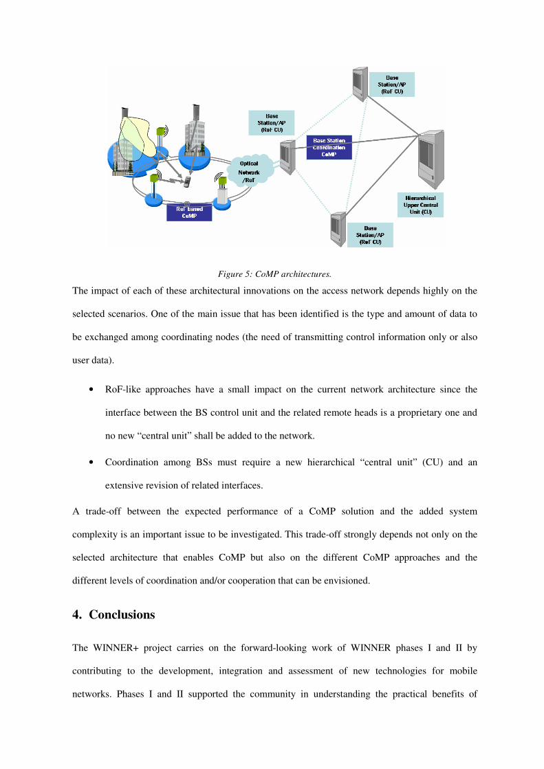
Figure 5: CoMP architectures.
The impact of each of these architectural innovations on the access network depends highly on the
selected scenarios. One of the main issue that has been identified is the type and amount of data to
be exchanged among coordinating nodes (the need of transmitting control information only or also
user data).
• RoF-like approaches have a small impact on the current network architecture since the
interface between the BS control unit and the related remote heads is a proprietary one and
no new “central unit” shall be added to the network.
• Coordination among BSs must require a new hierarchical “central unit” (CU) and an
extensive revision of related interfaces.
A trade-off between the expected performance of a CoMP solution and the added system
complexity is an important issue to be investigated. This trade-off strongly depends not only on the
selected architecture that enables CoMP but also on the different CoMP approaches and the
different levels of coordination and/or cooperation that can be envisioned.
4. Conclusions
The WINNER+ project carries on the forward-looking work of WINNER phases I and II by
contributing to the development, integration and assessment of new technologies for mobile
networks. Phases I and II supported the community in understanding the practical benefits of

techniques now in the 3GPP LTE and WiMAX standards (like OFDMA, MIMO and frequency-
adaptive scheduling). Furthermore, these previous phases were at the outpost for the design of
spectrum functionalities and relays, the latter being currently studied within the LTE-Advanced
Study Item and IEEE 802.16m. In the continuity of this work, WINNER+ focuses on the following
innovation areas for IMT-A technologies and their evolutions: advanced RRM, spectrum
technologies, terminal-to-terminal (peer-to-peer) communications, network coding, advanced
antenna schemes and coordinated multipoint systems. The system integration of the innovations will
be optimized to yield a WINNER+ system concept designed on the basis of LTE Release 8. An end-
to-end performance assessment of this system concept will be carried out by means of system-level
simulations as well as analytical calculations, using the system requirements and the evaluation
criteria defined by ITU-R. By joining the research forces of major players in the mobile
communication industry and academia ahead of standardization, the WINNER project aims at
fostering the consensus building on new technologies at an early stage, thereby easing the
standardization process for the benefit of the whole community.
Acknowledgements
This article has been written in the framework of the CELTIC project CP5-026 WINNER+. The
authors would like to acknowledge the contributions of their colleagues.
References
[1] ITU-R Circular Letter 5/LCCE/2, “Invitation for submission of proposals for candidate radio interface
technologies for the terrestrial components of the radio interface(s) for IMT-Advanced and invitation to
participate in their subsequent evaluation”, March 2008.
[2] WINNER Project IST 2004-507581, WINNER II Project IST-4-027756 and WINNER+ Project
CELTIC CP5-026, http://projects.celtic-initiative.org/winner+/.
[3] IST-WINNER II D6.13.14‚“WINNER II System Concept Description“, Dec 2007.
[4] C. Wijting et al., “WINNER II System Concept: Advanced Radio Technologies for Future Wireless
Systems”, Proc. of ICT Mobile Summit, Stockholm, June 2008.

[5] C. Wijting et al., “Key technologies for IMT-Advanced Mobile Communication Systems”, IEEE
Wireless Communications magazine, to appear.
[6] H. Ekstrom et al., “Technical Solutions for the 3G Long-term Evolution”, IEEE Communications
Magazine, vol. 44, no. 3, pp. 38 - 45, March 2006.
[7] 3GPP TSG RAN, “E-UTRA; E-UTRAN; Overall description; Stage 2”, 3GPP Technical specification,
v8.4.0, March 2008.
[8] E. Dahlman, S. Parkvall, J. Sköld, P. Beming, “3G Evolution: HSPA and LTE for Mobile Broadband”,
Academic Press, Second Edition, October 2008.
[9] S. Stiglmayr, M. Bossert and E. Costa, “Adaptive coding and modulation in OFDM systems using BICM
and rate-compatible punctured codes”, Proc. of European Wireless Conference, Paris, April 2007.
[10] A. Osseiran et al., “A MIMO framework for 4G systems: WINNER concept and results”, Proc. of IEEE
SPAWC 2007, Finland, June 2007.
[11] T. Beniero, S. Redana, J. Jyri Hämäläinen, B. Raaf, “Effect of Relaying on Coverage in 3GPP LTE-
Advanced”, IEEE Vehicular Technology Conference (VTC) Spring, April 2009.
[12] K. Doppler, S. Redana, M. Wodczak, P. Rost and R. Wichman, “Dynamic resource assignment and
cooperative relaying in cellular networks: Concept and performance assessment”, EURASIP Journal on
Wireless Communications and Networking, submitted to.
[13] E. Lang, S. Redana, B. Raaf, “Business Impact of Relay Deployment for Coverage Extension in 3GPP
LTE-Advanced”, LTE Evolution Workshop at ICC 2009, 14-18 June 2009.
[14] International Telecommunications Union, “Final Acts of the 2007 World Radiocommunication
Conference”, Geneva, Switzerland, 22 October - 16 November 2007.
[15] R. W. Yeung, S.-Y. R. Li, N. Cai and Z. Zhang, “Network Coding Theory”, Now Publishers, July 2006,
ISBN-10: 1933019247.
[16] L. Xiao, T. Fuja, J. Kliewer and D. Costello, “A network coding approach to cooperative diversity”,
IEEE Transactions on information theory, vol. 53, no. 10, pp. 3714 – 3722, October 2007.
[17] H. Weingarten, Y. Steinberg and S. Shamai, “The capacity region of the Gaussian multiple-input
multiple-output broadcast channel”, IEEE Transactions on Information Theory, vol. 52, no. 9, pp. 3936 -
3964, 2006.
[18] M. Sternad, T. Svensson, T. Ottosson, A. Ahlen, A. Svensson and A. Brunstrom, “Towards systems
beyond 3G based on Adaptive OFDMA transmission”, Proc. of IEEE, vol. 95, no. 12, pp. 2432-2454,
December 2007.

Figure 1
2007 2008 2009 2010 2011
LTE CR phase
LTE-Advanced SI Work Item
Proposal
Evaluation
Specification
LTE
WINNER II WINNER+ Research
Standardization
Regulation (IMT-Advanced)
Deployment

Figure 2
segmentation
MUX
FEC FEC
MOD MOD
LDC LDC
segmentation
FEC FEC FEC
segmentation
FEC FEC FEC
MOD MOD
LDC LDC
chunk layers
transport block ktransport block 1 transport block K
modulated chunk layers
virtual antenna chunks
FEC blocks (or encoded segments of transport blocks)
LPLP
GMC
Antenna summation
chunk 1 chunk c chunk C
Assembly of chunks to raw symbol data
IFFT
CP
IFFT per antenna
CP extension
To RF
FEC
segments of transport blocks
ResourceScheduler .
.
Time
CQI, CSI
CQI errorsNon-frequency adaptive
- Link
Frequency adaptiveBuffer levels
Map on dispersed chunks Map on optimal chunksPacketprocessing
segmentation
MUX
FEC FEC
MOD MOD
LDC LDC
segmentation
FEC FEC FEC
segmentation
FEC FEC FEC
MOD MOD
LDC LDC
chunk layers
transport block ktransport block 1 transport block K
modulated chunk layers
virtual antenna chunks
FEC blocks (or encoded segments of transport blocks)
LPLP
GMC
Antenna summation
chunk 1 chunk c chunk C
Assembly of chunks to raw symbol data
IFFT
CP
IFFT per antenna
CP extension
To RF
FEC
segments of transport blocks
ResourceScheduler .
.
Time
CQI, CSI
CQI errorsNon-frequency adaptive
- Link
Frequency adaptiveBuffer levels
Map on dispersed chunks Map on optimal chunksPacketprocessing

Figure 3
UE
UE
RN
eNB
access link
relay link
access lin
k
multi-hop link
UE
UE
RN
eNB
access link
relay link
access lin
k
multi-hop link

Figure 4
RRC
RLC
MAC
PHY
RRC
RLC
MAC
PHY
RRC2
RLC
MAC
PHY
RRC2
Transport
Network
Transport
Network
UE RN eNB
Gateway
RRC
RLC
MAC
PHY
RRC
RLC
MAC
PHY
RRC2
RLC
MAC
PHY
RRC2
Transport
Network
Transport
Network
UE RN eNB
Gateway

Figure 5

Authors Biographies
Afif Osseiran [M] ([email protected]) received a B.Sc. degree in Electrical Engineering (EE) from Université de Rennes I and INSA Rennes in 1997, and a M.A.Sc. degree in EE from École Polytechnique de Montreal, Canada, in 1999, and a Ph.D degree from the Royal Institute of Technology (KTH) in Stockholm in 2006. Since 1999 he has been with Ericsson, Sweden. In WINNER-II, he led the MIMO task. Since April 2008, he has been the technical manager of the WINNER+ project and also leading the system concept design work package. Eric Hardouin ([email protected]) received a Ph.D. degree in signal processing and telecommunications from the University of Rennes I (prepared at the ENST de Bretagne) in 2004. He then joined Orange Labs, where he has conducted or supervised research on various PHY or PHY-MAC techniques for interference mitigation in mobile networks. Since April 2008, Eric has been leading the Innovations work package of WINNER+. In addition, since August 2008 he has been representing Orange in 3GPP RAN WG1. Mauro Boldi [M] ([email protected]) received his Dr.Eng. degree in electronic engineering from Politecnico di Torino, Italy, in 1997 and a Master degree from SSGRR in L’Aquila, Italy, in 2001. Since 1998 he has been with Cselt, the research centre of Telecom Italia, now Telecom Italia Lab, working on mobile access networks innovation. He is currently participating in the Celtic Winner+ project where he leads the activity on coordinated multipoint systems (CoMP). Ivan Cosovic ([email protected]) received the Dipl.-Ing. degree in electrical engineering from the University of Belgrade, Serbia, in 2001, and the Ph.D. in electrical engineering from the Johannes Kepler University, Linz, Austria, in 2005. From 2002 to 2006, he was with the Institute of Communications and Navigation, German Aerospace Center (DLR), Wessling, Germany. From 2006 to 2009, he was with DOCOMO Euro-Labs, Munich, Germany. He led the link level procedures task and the spectrum task in WINNER-II and WINNER+, respectively. Karine Gosse([email protected]) received her Master’s degree (1993) and Ph.D. (1996) from the Ecole Nationale Supérieure des Télécommunications, Paris, France. She joined Motorola Labs, Paris from 1996 to 2008 where she worked in the area of wireless communications and smart antenna as research engineer, team leader, research and program manager. Her areas of research interest include beyond 4G radio interface. In 2008 she was responsible for Motorola contribution in WINNER+. Since 2009, she joined the CEA (Commissariat à l'Energie Atomique. Alexandre Gouraud ([email protected]) received his engineering degree from Ecole Nationale Supérieure des Télécommunications de Bretagne and Master degree from University of Rennes I in 2001. He worked for Turbo Concept for three years on advanced modulation and coding schemes for satellite communications. Since 2005 he has been with France Telecom where he is charge of the 4G radio upstream research activities , and participating in the system concept design work package of the WINNER+ Celtic Project. Jijun Luo ([email protected]) received his Master of Engineering (M. Eng.) degree form Shandong University, China 1999 and Master of Science (M. Sc.) degree from Munich University of Technology, Germany in 2000 respectively. He joined SIEMENS (now Nokia Siemens Networks) in 2000 and pursued his Ph.D. degree at RWTH Aachen University, Germany. He has published more than a hundred technical papers, co-authored five books. He is leading research activities in European research projects and active in international industrial standardization bodies. Jose F. Monserrat [M] ([email protected]) received his M.S. degree with High Honors and Ph.D. degree in electrical engineering from the Polytechnic University of Valencia (UPV) in 2003 and 2007, respectively. He is currently an associate professor in the Communications Department of the UPV. He is currently participating in the WINNER+ project where he is leading the research activities focused on the definition of RRM techniques for IMT-Advanced. Tommy Svensson ([email protected]) is assistant professor/project leader in Communication Systems at Chalmers University of Technology, Sweden. He obtained his PhD in information theory from Chalmers in 2003. He has worked in the EU FP6 WINNER projects, in WINNER II as the task leader of multiple access. In CELTIC WINNER+ he works on CoMP techniques and the system concept. He is also leading an academic IMT Advanced project. He has co-authored more than 30 scientific papers and more than 20 WINNER projects reports. Antti Tölli ([email protected]) received his M.Sc. and D.Sc (Tech) degrees in electrical engineering both from the University of Oulu, Oulu, Finland in 2000 and 2008, respectively. From 1998 to 2003 he worked for Nokia Networks, IP Mobility Networks division as Research Engineer and Project Manager both in Finland and Spain. In 2003 he joined the Centre for Wireless Communications (CWC) at University of Oulu, Finland where he is currently managing CWC's research activities in WINNER+ project.

Albena Mihovska ([email protected]) has degrees in M.Sc. (1999) and PhD (2009) in electrical engineering. She is currently an Associate Professor at the Center of TeleInfrastruktur at Aalborg University, Denmark. Albena Mihovska has been involved in the development of the WINNER system concept since 2004, in particular in the area of cooperative radio resource management and the final system requirements. Currently, she is working on the integration of the cooperative radio resource management framework with the framework for dynamic spectrum use. Simone Redana [M] ([email protected]) received his M.Sc. in Communication Engineering in 2001 and his PhD degree in 2005 from Politecnico di Milano. From June 2005 to May 2006 he worked in Azcom Technology as consultant for Siemens Communication. Since April 2007 he has bee with Nokia Siemens Networks in Milan (Italy) and Munich (Germany). He contributed to the EU WINNER II Project on relaying concept) and to the Eureka Celtic project WINNER+ (system concept design). Marc Werner [M] ([email protected]) received a diploma (Dipl.-Ing.) degree in Electrical Engineering from RWTH Aachen University in 1999, and a doctoral (Dr.-Ing.) degree in Communications Engineering from RWTH Aachen University in 2006. Since 2006, he is with QUALCOMM CDMA Technologies GmbH in Nuremberg, Germany. In WINNER II, he led the task “Standardisation, Requirements, and Deployment”, and since April 2008, he is the leader of work package “Performance Assessment” in WINNER+. Werner Mohr ([email protected]) received his Master Degree from the University of Hannover, Germany in 1981 and the Ph.D. degree in 1987. He was with Siemens AG, Mobile Network Division in Munich, Germany since 1991. Werner Mohr was project manager of the EU ACTS FRAMES Project (1996 to 1999. Since April 2007 he is with Nokia Siemens Networks in Munich Germany, where he is Head of Research Alliances. He was the coordinator of the EU WINNER Project and now of the Eureka Celtic project WINNER+. -----------------------------------------------------