the robocon diary 2012-2013 - indian institute of ...roboticsclub.iitd.ac.in/robodiary/robocon...
TRANSCRIPT

THE
ROBOCON
DIARY
2012-2013
Robotics Club
Indian Institute of Technology Delhi
August 07, 2013

PREFACE
The most important focus of this diary is the National ROBOCON, 2013. It
provides you with an insight into the details of each robot, technologies used and
further improvements. The year 2003 saw IIT Delhi’s first active participation in
ROBOCON, an annual ROBOtics CONtest. So far IIT Delhi has become
champion once (in 2007), reached semi-finals four times (in 2003, 2004, 2006,
2008), and was in quarter-finals twice (in 2005 as well as in 2009). Over the
years we have improved in terms of the quality of robots that we make, the
components that we use and the techniques we implement. “ROBOCON” is not
just about competing and winning. We learn a lot, not only in the field of
robotics but also about project management, time management and most
importantly, about team work. Apart from ROBOCON, the robotics club, IIT
Delhi made its presence felt all across the campus and in technical festivals of
various other universities.
All of above was possible only with the sincere efforts of Prof. S.K. Saha,
and more recently with the support of Dr. Kolin Paul, and the help from the
ROBOCON team.
At the outset it is to be remembered that always trying new technologies
need not lead to the wining robots, as the technologies do not get matured. Hence,
the robots may fail at ease. In order to win ROBOCON 2014, tested technologies
in the previous years must be respected just like any other technologies in the
market.
……….………….…………........……………………………………………………
This diary has been compiled by Shivang Shekhar

ACKNOWLEDGEMENTS
The team members of ROBOCON 2013 sincerely acknowledge the
financial and logistic support provided by Prof. R. K. Shevgaonkar,
Director of IIT Delhi, and his complete administrative and moral support;
without whose blessings we would not be able to participate year after year
in ROBOCON. The support of Prof. Anurag Sharma, Dean of Academics
in helping us getting funds from IIT’s account to purchase the components
required for fabricating the robots. The help of Prof. S.K. Gupta, Dean of
Students and his office is also acknowledged for allowing us to work in the
Robotics Room of SAC. The ROBOCON team members would also like to
thank Prof. S.K. Saha, the team mentor and Faculty-in-Charge and Prof.
Kolin Paul for their guidance. Mr. Kamla Prasad, Assistant Registrars of
the Accounts and Stores and Purchase Sections are also thanked for speedy
actions on ROBOCON matters.
There is an endless list of people from different departments and sections of
this institute without whose supports and blessings the participation in DD-
MIT-ROBOCON 2013 would not have been possible.

AB U RO B O C ON 2013, PU N E, IN D IA
THE TEAM-2013
Prof. S.K. Saha and Prof. Kolin Paul (Team mentor and faculty in-charge)
Vishal Mehta (Mechanical)-(Team Coordinator and Leader)
Gaurav Kumar (Mechanical)-(Mechanical Coordinator)
Kunal Sethiya (Electrical)-(Electrical Coordinator)
Konik Kothari (Mechanical)-(Mechanical Coordinator)
o Shivang Shekhar ( Mechanical)
o Nitish Sharma (Mechanical)
o Mayank Khichar (Mechanical)
o Aayush Agrawal (Mechanical) o Deepak K. Mishra ( Mechanical)
o Chayan Sharma (Electrical)
o Shubham Agarwal ( Electrical)
o Aman Kumar Jha (Mechanical) o G. Nitesh Bhardawaj (Electrical)
o Mohit Agarwal (Electrical) (Manual Rider)
o Abhishek Laddha (Electrical)
o M. Anil Chandra Naidu (Electrical) o Piyush Gupta (Mechanical)
o Aman Ruhela (Mechanical)
Rishabh Agarwal (Mechanical)
Shailesh B (Mechanical)
Third Yearites: 4
o Second Yearites: 14 First Yearites: 2
It is certified that all the above students have worked for DD-MAE-ROBOCON-2013 held in
Balewadi Stadium, Pune (March 7-9,2013) after working on the design, fabrication and
testing of the robots for the ROBOCON competition since September 2012 when the game
plan was declared in http://aburobocon2013.vtv.gov.vn/.


TABLE OF CONTENTS
Page no.
Chapter 1. The Contest Theme………………………………………. 1
Chapter 2. Rules…………………………………………………………….. 2
2.1 Quick Guide 2
2.2 Game Field and Objectives 3
2.3 Robot Specifications 5
2.4 Matches 6
Chapter 3. Design of Robots ………………………………………….. 9
3.1 Manual Robot 9
3.1.1 Tasks 9
3.1.2 Strategy 9
3.1.3 Final Design 10
3.1.4 Problems 11
3.2 Design of the bud and the Shooting Mechanism….. 12
3.3 Automatic Robot………………………………………………. 16
3.3.1 Tasks 16
3.3.2 Earliest strategy and design 16
3.3.3 Problems 20
3.3.4 Final Design 21

Chapter 4. Status before Going To Pune……………………………… 22
Chapter 5. Experiences……………………………………………………… 23
5.1 Event details 23
5.1.1 League Matches 23
5.1.2 Things learnt from the robots of other teams 24
5.2 Photo Gallery 26
5.3 Some Personal Experiences 28
References……………….………………………………………………………. 30
Appendix I : CAD Drawings and Photos…………………………. 31
Appendix II: Algorithms………………………………………..………… 34
Appendix III: Circuit Diagrams……….………………………..……….. 38

1 | P a g e
Chapter 1 THE CONTEST THEME
“THE GREEN PLANET”
Each nation is a piece of the puzzle that forms the world
The galaxy is vast and has experienced billions of years of collision and gravity
attraction. Objects were thus formed and life began. The planet that is called THE
EARTH has been chosen to nurture the seeds of life.
The first Ring that stirred to wake chose for itself the colour Green - the colour of
life.
The green spreads from ancient woodlands to fields and plains, creating a soft,
refreshing space that nourish the soul.
Along with economic development, people and their negative impacts have been
causing the green to disappear on the planet. It is spreading like an epidemic,
threatening the green planet and the life on it. Natural disasters, floods, climate
change ... The nature is raging.
People's and individuals' awareness is the best vaccine to prevent the disasters that
the Earth has to suffer.
Vietnam has chosen the theme THE GREEN PLANET for the ABU
ROBOCON 2013 with the message: “Each nation is a piece of the puzzle that
forms the world; the responsibility to protect the earth thus lies on the shoulder of
each person living on it.
Awareness and actions - that is what we need to sustain life in our common home
THE EARTH”.

2 | P a g e
Chapter 2 R U LES
2.1 QUICK GUIDE:
Duration of the game is 3 minutes
Figure 1 Game field
Each team will have 2 Robots
1 Automatic Robot
1 Manual Robot; Manual Robot is not allowed to enter the Earth Zone.
The Manual Robot picks up the Leaves in the “Leaves Store” and places them in the 3
Rings in the Southern Hemisphere.
Then, the Manual Robot loads "Leaves" which have been picked up from the “Leaves
Store” onto Automatic Robot.

3 | P a g e
The Automatic Robot must place at least 3 leaves in the Northern Hemisphere (including
two leaves in its own zone and at least one leaf in the common zone), then it is allowed
to touch the Bud(s) in the Northern Hemisphere.
The Automatic Robot goes to the North Pole Zone and picks up the Buds (made by the
team) and loads them into the Manual Robot.
The Manual Robot stands below the Limit Line 2 and throws the Bud(s) at the Moon. If
the team’s Bud stands successfully on the moon, the team achieves “THE GREEN
PLANET” and wins the game.
2.2 GAME FIELD AND OBJECTS
The Game Field consists of an area having the dimension of 13000mm x 13000mm made
by emulsion painted plywood and surrounded by an iron fence (100mm height-50mm
thickness). The game field is divided equally by an iron fence (60mm height, 30mm
thickness), along the Prime Meridian. (Reference Figure 1)
The Game Field is divided into 2 parts as follows:
The Earth Zone (see drawing for more details).
The Earth Zone is in Sphere Shape. It has a diameter of 8500mm. The white guidelines
made of matt (non-shiny) sticker of 30mm width represent the Meridian and the Parallel.
A picture of a green tree is drawn, inside the Earth Zone.
There are 7 steel Rings (painted in dark green) in which to place the Leaves in each
team’s Earth Zone. Each Ring is of following dimension; 50mm height; 25mm thickness
and the inside diameter is 350mm. The surface of the game field where the Rings are
placed in the Common Zone are painted in yellow. The surface of the game field where
other Rings are placed are painted in white (see drawing for more details).
The Northern Hemisphere (see drawing for more details) is the upper half of the Earth
Zone. There is the Common Zone that covers 4 spaces in the center of the Northern
Hemisphere (see drawing for more detail). Also, there is the North Pole Zone defined by
The First Parallel, where each team arranges their Buds before the game start. (See
drawing for more details)
The Southern Hemisphere is the lower half of the Earth Zone.

4 | P a g e
The Space Zone surrounds the Earth Zone (see drawing for more details).
There is the Moon in the Space Zone. The Moon is a round plate laid flat on top of the
cylindrical stand. The height from the surface of the Moon to the surface of the contest
field is 1500mm; The Moon is positioned along the Prime Meridian and the distance from
the North Pole to the center of the Moon is 2700mm.
There are 2 Limit Lines (30mm width), namely Limit Line 1 is the continuation of the
Equator; Limit Line 2 is drawn at 2950mm north of the Equator. (See drawing for more
details)
The Manual Robot Area
The Manual Robot Area is the Space Zone and it is painted cyan.
Manual Robot Staring Zone
The dimension of the Manual Robot Starting Zone is 700 mm x 700 mm which is painted
in red for Red Team and in blue for Blue Team.
Leaves Store
Each team’s Leaves Store is located at the bottom of the game field. Before the Game
starts, 12 Leaves will be arranged in the each Leaves Store (see drawing for more details).
The Automatic Robot Area
The Automatic Robot Area is the Earth Zone and the surrounding area. There are 02
Automatic Robot Staring Zones that have the dimension 700 mm x 700 mm, painted Red
for Red Team and Blue for Blue Team.
The Leaf
Leaves are in the shape of a cylinder (250mm Diameter, 200mm Height, 200g Weight).
Leaves are made of high-density polystyrene and are coated with emulsion paint, in red
for Red Team and blue for Blue Team. The top and the bottom of the leaves are both
pained in green.
The Bud
Each team must make 3 ‘Buds’ in the shape of a tree.
The height of the Bud must exceed 500mm;
The diameter of the widest part of the ‘Bud’ must exceed 300mm

5 | P a g e
The diameter of the bottom of the Bud must exceed 150mm;
The maximum weight must not exceed 300g.
The ‘Buds’ must be placed by each team before the start of each match. The ‘Buds’ can
be arranged in any ways as long as they are placed within the team’s North Pole
Zone.
The robot must be designed so that the ‘Bud’, under no matter what condition, cannot
travel more than 8m when the ‘Bud’ is thrown from the robot. The travel distance of the
‘Bud’ will be measured from the ‘Bud’ to the robot’s contact surface of the game field.
The Bud which has been thrown once cannot be used again in the same match.
2.3 ROBOT SPECIFICATIONS:
Manual Robot
The Manual Robot has to be operated via remote control using a cable connected to it or
remote control using infrared rays, visible rays or sound waves. Controlling using radio
waves is not allowed. Operators are not allowed to ride on their Manual Robot.
When operating via cable, the connecting point of the cable to the robot must be at least
1000mm from the ground. However, the length of the cable from the Manual Robot to
the control box must not exceed 3000mm.
There is a size limit (700mm L x 700mm W and 1200mm H) for the Manual Robots at the
Manual Robot Start Zones when the game starts.
After the game starts, the Manual Robot’s size and form may be changed. However, the
extension limit is 3m in diameter when checked from above.
Manual Robots are not permitted to separate during the game.
Only 1 member of each team is allowed to control the Manual Robot in the Game Field.
Automatic Robot
Automatic Robot must be completely autonomous.
When the Automatic Robot starts, team members are not allowed to touch the Robot.

6 | P a g e
Automatic Robot should fit within the size of 700mm L x 700mm W and 1000mm H at its
Start Zone before starting.
After the game starts, the Automatic Robot’s size and form may be changed. However,
the extension limit is 2m in diameter when checked from above.
Weight
All Manual and Automatic Robots, including their power sources, cables, remote
controller and other parts of each Robot shall be weighed prior to competition. The total
allowable weight of all Robots for each team to be used throughout the contest must not
exceed 40kg.
2.4 MATCHES
Duration of the Match
Before the match begins setting of the Robots need to be completed within 1 minute
after receiving the signal for setting.
Each match shall last for 3 minutes
However, the first team to achieve “THE GREEN PLANET!” wins the match regardless of
the point collected by the opponent. The match ends when “THE GREEN PLANET” is
achieved.
Competition Rules
The Manual Robot picks up the Leaves in the “Leaves Store” and places them in the 3
Rings in the Southern Hemisphere;
After placing Leaves successfully in the 3 Rings in the Southern Hemisphere, the Manual
Robot can load Leaves onto the Automatic Robot in the Automatic Robot Start Zone or
the Manual Robot can carry the Leaves to the Limit Line 1 and drop the Leaves onto the
floor of the Game Field. Any parts of the Manual Robot which are in contact with the
floor of the Game Field shall not be allowed to cross over the Limit Line 1;
After the Manual Robot fulfilled the task under 4.2.2, the Automatic Robot is allowed to
start;

7 | P a g e
The Automatic Robot goes to place the Leaves in the Rings in the Northern Hemisphere
of their own game field and the Common Zone.
The Automatic Robot can place maximum of 5 Leaves in the Rings in the Northern
Hemisphere and the Common Zone. However, it is allowed to place only 1 Leaf in the
opponent’s side of the Common Zone.
After the Automatic Robot successfully placed at least 3 Leaves in the Northern
Hemisphere including 2 leaves outside of Common Zone:
The Automatic Robot is allowed to pick up the Bud(s) which are placed in the North Pole
Zone;
Once the Automatic Robot picked up any Bud(s), the Automatic Robot cannot place any
more Leaves in the Rings.
The Manual Robot can cross the Limit Line 1 to receive the Bud(s) from the Automatic
Robot and throws the Bud(s) at the Moon. However, when throwing the Bud(s) at the
Moon, the Manual Robot has to stand behind Limit Line 2.
Once the Bud(s) thrown by the Manual Robot successfully stands in the Moon, “THE
GREEN PLANET” is achieved and the match ends immediately. If neither team achieves
“THE GREEN PLANET” within 3 minutes, the team with more score will win the match.
Points Award
The team gains point when their Robots successfully place their own Leaves in the Rings.
Scoring:
Place the Leaf in the Earth Zone: 10 points/Leaf
The Manual Robot receives the Bud from Automatic Robot: 10 points/Bud
Violations and deduction of points
The following actions will be regarded as violations and 10 points will be deducted for
each violation:
Robot enters or extends over opponent’s zone (except Common Zone).
The Manual Robot enters the Earth Zone.

8 | P a g e
The Automatic Robot starts before it is allowed pursuant to 4.2.2.
Automatic Robot continues to place Leaves after picking up the Bud(s).
The act of using adhesives for the ‘Buds’ to stand in the Moon or to pick up objects in
the game field and leaving adhesives on any objects, contest tools and the game field is
strictly prohibited.
Robots move out of the game field.
Start before referee’s whistle or signal.
DECIDING THE WINNER
The first team to achieve THE GREEN PLANET shall be the winner.
If the two teams achieve THE GREEN PLANET at the same time or neither team achieved
THE GREEN PLANET within 3 minutes, the winner will be decided by the following
priorities:
Total scores after points deduction in that match (if any).
Time record of the first Bud(s) to be received by the team’s Manual Robot.
The first team accomplishes the mission in 4.2.1.

9 | P a g e
Chapter 3 DESIGN OF ROBOTS
3.1 Manual Robot
3.1.1 Tasks Picking up of leaves from the leaves store
Placing them in the three rings of the Southern Hemisphere
Placing the leaves for the Automatic Robot
Taking the bud from the Automatic robot
Shooting the bud at the moon
3.1.2 Strategy
The strategy was as follows:-
The manual robot starts and goes to the leaves store.
Using the front three grippers, it grabs the leaves and then turns 180 degrees.
It then grabs three more leaves using the three back grippers.
It moves towards the southern hemisphere and drops three leaves in the three
rings using the front grippers.
It then moves towards the starting zone and drops the three leaves in front of the
automatic robot.
If required it goes again and brings more leaves using the three back grippers and
drops in front of the automatic robot.
After this, it waits for the automatic robot to complete the task and then takes the
bud from it. This process will be clear after the description of the bud.
It then shoots the bud using a high pressure air supply.
3.1.3 Final design
One design was finalised on the basis of speed, task completion and reliability.
Mechanical aspects
o The robot had a four wheel holonomic drive for easy traversal and rotation.

10 | P a g e
o It had 6 pneumatic grippers, three at the front and three at the back.
o The three back grippers were attached to the main body using three revolute
joints, so that when they drop down they are able to grip three leaves.
o The middle gripper at the front was attached over an expandable arm to drop the
leaf at the ring farthest from the manual zone.
o The two side grippers at the front were attached to two separate rack and pinion
mechanisms for dropping the leaves in the other two rings.
o The three back grippers placed the leaves in front of the automatic robot exactly
as it picked from the leaves store.
o Over the bot there was a shooting mechanism, which was a hollow aluminium rod
connected to an air supply and adjusted using a pulley mechanism.
Electrical
Objective
To redesign and augment the manual robot, designed by mechanical guys, with
sensors so that the manually controlled part of the mechanical robot (as mentioned
in Appendix I) can be completed in the minimum time possible
Components used in our design
Inertial Measurement Unit(IMU) with onboard ATMega328 and Serial output, PS2
Remote for manual control, Sabertooth DC-DC converter driven PMDC motors, Light
Sensors for curve tracing, Solenoid-valves to drive pistons, MOSFET based controllers
for solenoid-valves, IR transmitter, Inexpensive High Torque PMDC Motors and above
all Arduino Microcontroller (to encode the commands given by PS2 and parallel
execute different functions)
Sub-Objectives
o To use the sensor data from IMU to produce a Heading Reference System which
gives the heading/direction of the robot in 2 Dimensions (Direction Cosine Matrix-
DCM Implementation to fuse accelerometer and gyroscopic data)
o Interfacing Light sensors with Auto-calibration feature and designing feedback
mechanism for curve tracing

11 | P a g e
o To interface PS2 remote with the microcontroller so that it is convenient for the
manual controller to control the robot
o Interfacing all the solenoid and motor drivers with the microcontroller
o Adding mechanical limit switches and PMDC motors for gripper movements and
including their functions into the microcontroller
o Breaking up the task to be done on the arena into subtasks, automating each
subtask and adding a function to the PS2 to switch through these automated tasks
easily
o Adding back button to PS2 to undo the subtask already done in case the task is
wrongly completed. Also, adding a button to switch the control completely to
human controller if tasks fail badly in the particular task
o Debugging and making the bot competition ready
For details of the design see Appendix II.
3.1.4 Problems
There were many problems faced some of which are as follows:-
Four point contact
The main problem in the manual robot was the four point contact. After trying many
things springs were used between the motor mounting and the chassis. This was not a
good choice since this affected the stability of robot.
Weight
Weight was also a problem. In an earlier design, the two side grippers were mounted
over an arm which was geared to a power window. The gears, being of Mild Steel, and
arms increased the weight so much that we had to remove them.
Motor axle
The major problem in the driving motors was that the axle was of diameter 6 mm only
which turned out to be not enough to drive the robot smoothly. This problem was
identified much later and so it persisted.
Repeated mechanical iterations

12 | P a g e
Due to constant mechanical iterations, the electrical guys had to start fresh each time.
This was a major problem and delayed the practice of the robot.
3.2 Design of the bud and the Shooting Mechanism
The addition of new rules for the making of the bud was as follows:-
1. The Bud must consists of ‘root’, ‘trunk’ and ‘branches and leaves’. The ‘root’ and
the ‘branches and leaves’ must be directly attached to the trunk. The ‘root’ must
be situated at the bottom of the Bud and must be painted brown for an easy
recognition. There must be minimum of three ‘branches and leaves’ and they
must be painted green.
2. The root of the Bud must be in contact with the contest field when the Bud is
place in the North Pole Zone. The overall height of the Bud must exceed 500mm in
vertical when placed in the North Pole Zone. However, the longest part of the Bud
must not exceed 1000mm during the match.
3. When the Bud is placed in the North Pole Zone, the widest part of the Bud must
exceed all sides of a 300mm square when checked from right just above.
4. There must always be a portion protruded from all the circumferences 150 mm in
diameter during a game in a root. The widest part of the root must be over
150mm but should not exceed 250mm during the match.
5. The weight of the Bud must be less than 300g during the match. There is no limit
for minimum weight.
As long as the Buds satisfy the conditions under the rule 2.6.1-2.6.5, they can be placed
at anywhere within the team’s North Pole Zone. However it is prohibited to enter
opponent’s zone including its space above.
Initial ideas for the shooting mechanism included the following:
1. Spring based mechanism: The design consisted of a square platform attached to 4
springs near its four vertices. The springs were compressed using a motor and
then the coupling between the motor and platform was retracted to cause a
sudden change in momentum of the object placed on the platform. Initially, a
range of only about 2 meters was achieved; but by using springs of correct
stiffness and smoother, good quality bearings, we were able to achieve a range of
5 meters which was required to complete the task. Major problems with this
13 | P a g e
mechanism were its bulkiness and high current requirements. (See Figure 2)
2. Exhaust Air Mechanism: In this design, the bud was supposed to be in the form of
a bottle filled with compressed air. Once in position, the valve at the inlet was
retracted to cause the compressed air to flow out providing the bud with a
forward momentum. The problem with this mechanism was that the valve
retracting mechanism was proving to be difficult to fabricate and also the range
achieved with a maximum pressure of 6 bar was not enough for the task.
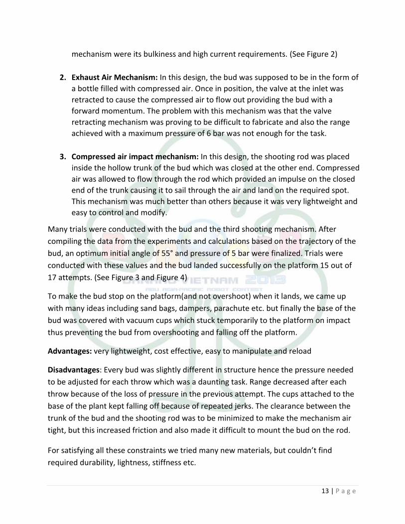
3. Compressed air impact mechanism: In this design, the shooting rod was placed
inside the hollow trunk of the bud which was closed at the other end. Compressed
air was allowed to flow through the rod which provided an impulse on the closed
end of the trunk causing it to sail through the air and land on the required spot.
This mechanism was much better than others because it was very lightweight and
easy to control and modify.
Many trials were conducted with the bud and the third shooting mechanism. After
compiling the data from the experiments and calculations based on the trajectory of the
bud, an optimum initial angle of 55° and pressure of 5 bar were finalized. Trials were
conducted with these values and the bud landed successfully on the platform 15 out of
17 attempts. (See Figure 3 and Figure 4)
To make the bud stop on the platform(and not overshoot) when it lands, we came up
with many ideas including sand bags, dampers, parachute etc. but finally the base of the
bud was covered with vacuum cups which stuck temporarily to the platform on impact
thus preventing the bud from overshooting and falling off the platform.
Advantages: very lightweight, cost effective, easy to manipulate and reload
Disadvantages: Every bud was slightly different in structure hence the pressure needed
to be adjusted for each throw which was a daunting task. Range decreased after each
throw because of the loss of pressure in the previous attempt. The cups attached to the
base of the plant kept falling off because of repeated jerks. The clearance between the
trunk of the bud and the shooting rod was to be minimized to make the mechanism air
tight, but this increased friction and also made it difficult to mount the bud on the rod.
For satisfying all these constraints we tried many new materials, but couldn’t find
required durability, lightness, stiffness etc.

14 | P a g e
Finally we used hollow aluminium rods for the bud as the mechanism we had was a
pneumatic powered shooter.
Basic characteristics of the bud and the shooting mechanism were as follows:-
The shooting rod was also a hollow rod of lesser diameter, so it was inserted into
the bud.
When high pressure air was supplied, the bud flew due to the momentum of the
air.
The rod was welded at an angle with the base so that when launching took place
the base should be horizontal.
The bottom portion of the bud was of funnel shape to facilitate easy insertion of
the shooting rod.
Figure 2. Other mechanisms tried for shooting such as spring mechanism

15 | P a g e
Figure 3: CAD model of the bud
Figure 4: Bud throwing practice

16 | P a g e
3.3 Automatic Robot
3.3.1 Tasks
Getting leaves from the manual robot.
Placing leaves in the northern hemisphere.
Reaching the North Pole zone.
Grabbing the bud from the North Pole zone.
Getting into a position for the manual robot.
After manual robot takes the bud, leaving it and going for the next bud and so on.
3.3.2 Earliest strategy and design
After the release of the problem statement, due to the lack of detailing in it, it was
decided to first focus on the three rings of the northern hemisphere.
Since the rules regarding the bud were not released, anything about picking up the bud
or transferring it couldn’t be done.
Our strategy was this:-
o The manual robot puts the leaves over the automatic robot.
o The automatic robot starts and goes to a position between the rings and over the
white line.
o The two arms open and drop the leaves in the two rings.
o The third arm which is a conventional gripper drops the leaf over the ring in the
common zone.
o At a later stage, the design of this gripper can be changed for holding the bud
accordingly
Design
Mechanical
It was a three wheel holonomic robot to traverse in any direction without
changing its orientation.

17 | P a g e
It had two unconventional arms which when closed had a hole of size greater than
the leaf and concentric and when opened were able to reach above the two rings.
There was a rack and pinion mechanism in the lower arm to make it move outside.
Finally it had a big piston at the front end to drop the leaf in the opponent’s ring of
the common zone.
Pistons were attached to hit the leaf when it comes above the ring.
For moving the third arm earlier banebot motors were used which were later
replaced by robokits motors.
Motors were used for rotating the arms and moving the third arm up and down
using a pulley mechanism.
Two mouse were mounted parallel to each other near the omni wheels.
A mechanism was separately designed for the back portion of the manual robot so
that it is able to place the leaves in the same line. (See Figure 5 and Figure 6)
Figure 5: For picking up the leaves from the ground it was required to be on the same level
Figure 6: After picking it would have rotated and stacked like this

18 | P a g e
Electrical
The three omni wheels were placed at an angle of 120 degrees to each other so that
robot can be moved in any direction. Despite the advantage of robot being able to move
in any direction we can’t utilise it fully as the motors were not capable of providing
sufficient torque and hence our correction for keeping the robot at a particular angle was
not implemented properly.
Correction for Holonomic Drive: For correction in the motion of holonomic drive we
used the mouse sensor. We decided to use mouse sensor over conventional encoders as
mouse sensors are not surface dependent i.e., they don’t have much effect due to
slipping. Mouse Sensor work on the principle that the sensor takes continuous images of
the area under it and based on the change in the image it calculated the differential
change in its position (dx and dy). This differential change in the position can be used to
determine the position of robot and also the trajectory in which it is currently moving.
This information was used for correction in holonomic drive. But the problem was that
the error in dx and dy keeps on accumulating and hence it becomes significant after
moving small distance.
Algorithm for Correction: We used two mouse sensors for correcting the motion of
robot, since with one mouse we can only determine the position of robot but can’t
determine its orientation. The two mouse were placed in parallel to each other. Based on
the difference of the two mouse readings its error in orientation can be determined. We
took the difference in the reading of two mouse continuously and used a correction that
was proportional to the error generated. We used the PD (Proportionality and derivative)
controller for correction in its position. The correction was the angle that the robot
should move to correct its trajectory. Further to correct the orientation we provided it an
angular velocity proportional to the error.

19 | P a g e
Electrical Aspects (Components Used)
Microcontroller: We used the open source microcontroller Arduino. We used an Arduino
Mega and two Arduino Uno. We implemented parallel programming which was used first
time by any team in ROBOCON India. We established Serial Communication for
communicating between Mega which was the master and two Uno’s which were the
slaves. The Uno were used to interface the mouse sensor and send their data to the
Master whenever it ask for the data. Except for using in interfacing the mouse they were
also used for small purposes like controlling arms.
USB Host Shield 2.0: This device from SparkFun is used to interface any USB device from
the Arduino Microcontroller. This takes the reading from the USB device and sends it to
the Microcontroller using SPI communication protocol. This was used to interface mouse
sensor by the Arduino UNO.
Mouse: The mouse we used were from the Dell Inc. These mouse stores the dx and dy
(16-bit 2’s complement) reading in two buffers of 8 bits. Hence there were two registers
of 8-bit each for each of dx and dy. For getting the readings of dx and dy these registers
were read. The readings from two registers (X_High and X_low) were combined two get
the correct 16-bit 2’s complement. This was converted to decimal value by us for using in
any computation.
Motor Driver: The motor drivers we used for driving motors are Sabertooth Motor
Drivers. These could be used to drive two motors with current rating of 25A. These could
be used in many different modes and can be controlled by the PWM or Serial
communication. We used the packetized Serial communication in which upto 6 motor
drivers can be controlled by just one SERIAL. The packetized serial works on baud rate of
9600.
For controlling other motors we used the low current MOSFET motor drivers by the
company Robokits, which were controlled by PWM and a digital input for direction.
Line Following Sensors: We used the Photodiode Sensors which give different analog
values at different colours for line following. The problems with these sensors were that

20 | P a g e
there value was affected largely in different lighting conditions. Though once set up for
the lighting conditions they gave good response.
Encoders: The encoders we used were from the Vex Robotics. These gave 90 readings in
one complete rotation. They were used to measure the rotations of arms.
3.3.3 Problems
The major problems were as follows:-
The mechanism designed for stacking was not implemented correctly in the
manual robot. So the automatic robot was not at all compatible with the manual
robot.
Due to significant error accumulated in mouse sensors they were not that
effective and we used it just for alternate feedback.
The disadvantage of using the holonomic drive was that the speed of robot was
less in any given direction as compared to normal two wheel and a castor drive as
there was only a component of velocity available Holonomic Drive.
In this design, the reliability of leaves falling though the holes and landing upright
was not satiable.
Due to these problems the design was changed completely after the winter vacations
3.3.4 Final Strategy and Design
Mechanical
The earlier design was changed to a completely new one.
Now, we were picking the leaves from the ground using two arms with grippers. (See
figure 7)
The back portion of the manual robot was now compatible. It placed the leaves in the
front of the automatic robot.
Advantages

21 | P a g e
o The robot became light so the weight problem was reduced.
o It was easier to place the leaves in the rings.
Disadvantages Picking the leaves from the bottom with less clearance between them was very difficult.
Figure 7: Automatic robot picking up leaves from the ground
Electrical changes
The drive was retained as earlier. New sensors were now needed for starting operation.
Proximity Sensors: We used the Ultrasonic Sensors as the proximity sensors. These were
used to detect the distance of Leaves from the arms for gripping them.

22 | P a g e
Chapter 4 Status before Going to Pune
Before going to pune, we completed all the above mentioned objectives more or less.
We even completed the task except shooting in synchronization within three minutes.
However these were some of the concerns we had:-
The automatic robot was not able to grip the bud properly and transfer it without
rotation.
The idea of having a dummy plant as a backup was not able to be implemented.
This was required because transfer of plants had as much as 30 points.
The drive of the manual robot was of concern. Since the springs used for the four
point contact made the bot unstable and so it required frequent tightening of nut
bolts of the coupler connecting the motor and the shaft extender.
Due to space constraints, the other half of the field was not completed. So the
automatic robot didn’t get the chance to practice for the red zone at all.
There were still concerns about picking up of the leaves from the ground by the
automatic robot.

23 | P a g e
Chapter 5 Experiences
5.1 Events Details
5.1.1 League Matches
On reaching Pune, we didn’t take much time in finalising our robots and were ready
for our first practice slot.
In the first practice slot, the manual started and ran some time and the nut bolts
loosened earlier than expected. So it was returned to the pit area. The automatic
robot did pretty well except having some difficulties. It was not detecting a line
required for turning and iterations were required for proper placement of leaves.
In the subsequent practice slots, the problem of automatic robot was removed turn
by turn and also it was practiced for the other half. The automatic robot was now
able to complete the tasks and even lift a dummy bud for the manual robot which
was designed there only.
But the manual robot’s problem persisted each time. We tried many things but
nothing worked.
Series 1
In the first series of matches, the drive of the manual robot suffered. It moved
slowly as expected and had to be operated carefully. So, out of three only one time
the automatic robot was able to get started which resulted in earning just 90
points.
After this, we decided that we can’t continue with this drive further or else the
motors will get permanently damaged. In one night we changed the complete drive
with the spare Mechtek motors we got for the automatic robot since it had an axle
of diameter 12 mm. Only problem was it was very slow.

24 | P a g e
Series 2
In the next series of matches, we saw many ups and downs. In the first match, the
manual had problems but it was able to complete its task in two minutes. First time
our automatic robot earned points and dropped two leaves in the rings. It was
dropping two more but the time expired. However in the next two matches, the
manual struggled and the automatic robot didn’t get a chance to move. We ended
up with a total of just 160 points and thus first round exit from ROBOCON 2013.
5.1.2 Things learnt from the robots of other teams
The team MIT Pune had used very light fabricated grippers with a centre
piston mechanism. Thus they must have never faced problem related to
weight.
The idea of using spring couplers used by many teams for four point contact
and better stability was in our mind but we were not able to find the
manufacturer in time.
Teams such as Nirma University had extensively used pistons and they
designed like that so as to minimise the use of motors and problems related
with their feedback. (See Figure 8 and 9)
The type of gripper used by IIT Madras and COEP pune, was very good which
provided them more clearance by picking the leaves from above and using
just a point.

25 | P a g e
Figure 8: Nirma University manual robot
Figure 9: Nirma university automatic robot

26 | P a g e
5.2 Photo Gallery
Automatic robot (left) and manual robot (right) before leaving for pune

27 | P a g e

28 | P a g e
5.3 Some Personal Experiences
Participating in ROBOCON requires knowledge, application,
aptitude and above all perseverance to continue in spite of the
difficulties you face. This year what I learnt from ROBOCON was
an experience o f a lifetime. In the end it is not the result that
matters, what matters is the Journey and how you learn from
your mistakes. We saw many new things i mpl ement ed this
year such as navigation and correction through mouse, use of
pneumatics etc. It was great to explore a nd try such things.
Overall, working in Robotics Club is one of the most crucial
things I did coming i n lIT
- Shivang Shekhar (2nd year)
In future whenever I would be dejected, sparing a thought for
ROBOCON would suffice for an adrenaline boost. When at last it all
boils down to one whistle timing that may go awry and jeopardize
the months of tireless efforts of the team, it felt such a thriller to
be entrusted with such a responsibility. The way to ROBOCON is
long and troubling but it makes a real man out of you. Learning
while building (and blowing up :P) is the basic method here which
one keeps iterating. Only now I can comprehend that a big team
translates to a big rational product. But I believe that games are
not always the perfect way to compare your quotient. Overall
Great people, great time and great learning.
- Mohit Agrawal (2nd year)

29 | P a g e
I had the most amazing year at Robotics club working w i t h a team
of students from different b r a n c h and different year. I got to learn
a lot by conducting workshops for freshers, leading my team Into
a national competition, working together day in and day out and
combining all the efforts into a single robot. It feels wonderful to
make a masterpiece a f t e r successfully facing a lot of challenges. lt
was an enjoyable p r o c e s s of making robots for ROBOCON 2013.
This year we had many new technologies inducted in our robots and
we hope to continue t h i s innovating process for the coming years
as well. I hope the coming b a t c h puts in even more effort and
takes the Robotics club to new heights.
- Vishal Mehta
Overall co-ordinator
Robotics Club 2012-13
As a 1st year student i t was a great experience for me to see the
awesome event conducted on a very large scale. The teams from
all over India participated in the competition with only one
dream to win the title of ROBOCON. But for me it meant far too
more, it taught m e how to work as a team and never to lose
hope whatever t h e situation is. Working f o r ROBOCON m a d e
me familiar w i t h m a n y new technologies of great utility. I also
made a manual bot that responds according t o arm action. Over
all working f o r the club taught m e a lot and I also hope to work
more for the club.
- Rishabh Agarwal (lst year)

30 | P a g e
RE F E R E N C E S
1. http://www.arduino.cc/
2. http://www.igus.com/default.asp?C=US&L=en
3. http://www.dimensionengineering.com/sabertooth2x5.htm
4. http://www.ifm.com/ifmus/web/home.htm
5. http://www.mechtex.com/

31 | P a g e
Appendices
Appendix I:
CAD Drawings and Photos
Chassis of the manual robot

32 | P a g e
Design of the manual robot
Back portion of manual robot

33 | P a g e
Design of automatic robot earliest design
34 | P a g e
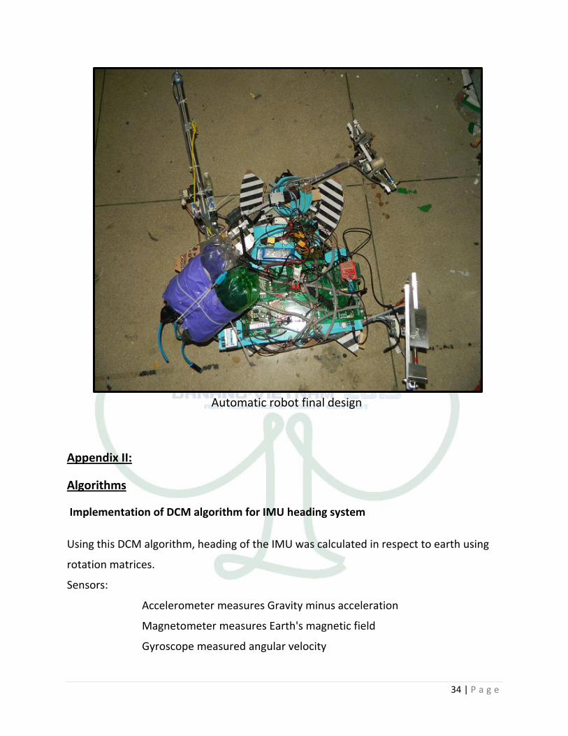
Automatic robot final design
Appendix II:
Algorithms
Implementation of DCM algorithm for IMU heading system
Using this DCM algorithm, heading of the IMU was calculated in respect to earth using
rotation matrices.
Sensors:
Accelerometer measures Gravity minus acceleration
Magnetometer measures Earth's magnetic field
Gyroscope measured angular velocity

35 | P a g e
Unaffected by gravitational or magnetic field, gyroscope sensor is the primary sensor
used to calculate orientation of system. Accelerometer and magnetometer are used to
obtain a reference vector. Gyroscope's have certain offset which when integrated causes
result to drift. The accelerometer is not affected by drift, therefore, it is used as an
orientation reference in the X and Z axis of the rigid body to compensate the roll-pitch
error (gyro’s offset error).
The magnetometer’s readings are used to calculate the heading of the rigid body. The
magnetometer must be three axes to be able to calculate the heading of the system in
any position of the sensor platform; to compensate yaw error. The heading of the system
used as the reference vector in the Y axis (yaw error), in addition to the roll-pitch error
calculated by the accelerometer, it allows the system to calculate the rotation correction
matrix. Afterwards, the algorithm uses a proportional plus integral feedback controller
on the correction matrix to the remove the drift from the gyro’s readings.
The compensated gyroscope values are then fed to the “Normalization & Kinematics”
block (as shown in figure). The rotation matrix’s columns are unit vectors. Thus, before
calculating the kinematics portion it must be normalized. Once normalized, the
gyroscope along with the previous rotation matrix is used to calculate the current

36 | P a g e
rotation matrix (R Matrix). Finally, the Euler angles are calculated from the updated
rotation matrix.
Reference: http://www.starlino.com/dcm_tutorial.html
Starlino Electronics // Spring, 2011
Interfacing and programming for PS2 controller
Technologies Used:
PS2 controller, SPI protocol, Parallel programming, EEPROM storage
Connections:
A Ps2 controller was used to control the manual bot. The complete manual
referenced is available at http://www.billporter.info/2010/06/05/playstation-2-
controller-arduino-library-v1-0/. The connections were made as mentioned in above
reference. Owing to error “No controller found. Check wiring" even after the procedure,
following steps were performed
1. Pull up the data line by connecting a resistor of 10k between data and 5V.
2. Change CTRL_CLK in ‘PS2X_lib.h’ from 2 to a higher value ranging from 4 to 100.
Step1 could remove the error.
Development
Initially the joysticks were used to control the motion of the bot. Since our manual
bot is of 4-wheel holonomic drive the four wheels are given velocity in order using the
ps2 controller. Left analog stick was used to control the linear motion of the bot. Right
joystick was used to control the rotation. Initially the manual bot was made to move in
16 directions by giving the velocity in a certain ratio to 4 wheels. A lookup table was used
to calculate the trigonometric values for motion. The bot was then made to translate by
cutting down the 360 degrees to 16 parts. When the joystick is kept at an angle in the
range of one of these 16 parts the bot is allowed to move in that direction. The analog
values of the analog stick (both x and y) range from 0 to 255.The readings of the analog
stick were discrete and non-linear. So a mapping to 16 directions is made by making

37 | P a g e
observations from the serial monitor for finding the range of analog values.
Strategy and Parallel Processing
After the arms were added the bot was to be made semi-autonomous. Initially
time was used to control the motion of the arms. The millis() function was used to find
the time and based on that the position of the arms was estimated. But the problem with
this method is that the motors being non-linear never had gone the same distance as
before. It resulted in breakage of arms. Later limit switches were used to control the
arms. Both limit switches and time were used in conjunction for more efficiency in case
one of them fails.
All the functions were called in parallel i.e. in the void loop every function is called each
time, which performs the function until its task is completed. This resulted in making the
bot perform parallel actions so that we could open the arms while in motion etc. The
entire task is divided into various modes and except motion, picking all actions were
made semi-autonomous so that if we click the mode button every time it resulted in the
bot performing the action by itself. There is a button to enter the previous mode in case
of a mistake in the action performed. Then the control of motion is transferred from
analog stick to analog buttons to prevent the confusion. In case the automation fails
there is a button to take back the control to perform the actions manually. Since there is
a need for restart in our game the code was made so as to skip from the one state to the
particular another state any time. Buttons on PS2 were Mode specific i.e. the whole task
of automation was divided into 32 modes and each button was designated a specific task
based on that mode. Then there is also a button to store the mode in EEPROM to load it
back in case of a restart.
Problems faced
1. The code had many bugs initially which resulted in the bot getting out of control
many times. The bugs were corrected over the time.
2. Another problem, which puzzled us, was mid-way failure of PS2 remote, which
resulted in an uncontrollable state of bot. For the same, Separate power was given to ps2
(not from arduino board).

38 | P a g e
Appendix III:
Circuit diagrams
1. Sensor plate (both sides)

39 | P a g e
2. Power Board
3. Automatic Robot (Both sides)

40 | P a g e
4. Manual Robot (Both sides)

41 | P a g e
For details of the code used by us for ROBOCON 2013, go to
http://goo.gl/AqrzuL