the role of small gaps behind wall claddings on drainage …€¦ · the role of small gaps behind...
TRANSCRIPT

11th Canadian Conference on Building Science and Technology Banff, Alberta, 2007
The Role of Small Gaps Behind Wall Claddings on Drainage and Drying
John Straube, Ph.D.
Civil Engineering Dept & School of Architecture, University of Waterloo Jonathan Smegal, M.A.Sc.
Building Science Consulting, Waterloo, Ont.
ABSTRACT
A common rain control strategy to help minimize moisture damage is the rain screen wall system. This approach requires a rainscreen, a drainage plane, flashing, weep holes, and a drainage gap. Although this approach to rain control is becoming the most common, and is sometimes even mandated by codes and standards, very little research has been undertaken to define the minimum or optimal gap size required for either drainage or ventilation drying.
A test method and experimental program were developed to investigate the gap size required to ensure drainage, and the role of small gaps on ventilation drying. Because of the importance of small geometrical details, full-scale wall systems were tested. The experimental method was able to gravimetrically determine the amount of drainage, storage and drying during and after a simulated wetting event. The test apparatus and method developed were shown to provide repeatable results over multiple tests as well as in an independent laboratory.
The experiments to date have conclusively shown that even small gaps (less than 1 mm) can drain more water than would normally be found in a drainage gap. It was also found that in some cases small gaps will store less water than a large drainage gap. It was also found that ventilation drying can play a role in very small gaps of approximately 1 mm, at a pressure difference of only 1 Pa. More research is required to further analyze optimal ventilation gap sizes and compare the laboratory results to hygrothermal modeling.
INTRODUCTION
Moisture in buildings is one of the leading causes of building enclosure failure. Moisture issues range from cladding staining to serious structural degradation. For moisture damage to occur four factors must combine: moisture availability, a driving force, a path, and a material that is moisture susceptible at the temperature conditions. Moisture damage will only occur when these four conditions are met, and the safe storage capacity of a material is exceeded. Some materials (such as masonry) can store much larger amounts for longer periods of time than other materials (such as paper-faced gypsum wall board) before exceeding their safe storage capacity.
It has been recognized for many years that using a drained approach to controlling rain penetration will often provide better control than other strategies such as perfect barrier and mass walls (Ritchie 1961, Lacasse et al 2003). A functional drained wall system comprises a rainscreen (a cladding that acts a screen to rain, sun, impact, fire and more), a drainage plane (a capillary break that resists inward transmission of liquid water), a flashing system to direct vertically drained water horizontally out, weep or drain holes to allow water to pass back out through the cladding, and a drainage gap or cavity. The role of the gap is to relieve the potential buildup of hydrostatic pressure due to gravity drainage of liquid water. If the gap is large enough, airflow through the gap can allow ventilation and drying.
If liquid water penetrates the cladding some water will be stored even in a wall system with drainage. Bulk water can be trapped in depressions in the wall system, or areas that are not
11th Canadian Conference on Building Science and Technology Banff, Alberta, 2007
drained properly. Water can also stored on surfaces by surface tension, and absorbed into most building materials by capillarity. Water vapour can also become adsorbed into building materials, or may be present in the air cavities in the enclosure. All of these mechanisms act to ensure that all water that penetrates is not drained. Hence to avoid moisture problems, some drying should be provided. (Straube & Burnett 1998)
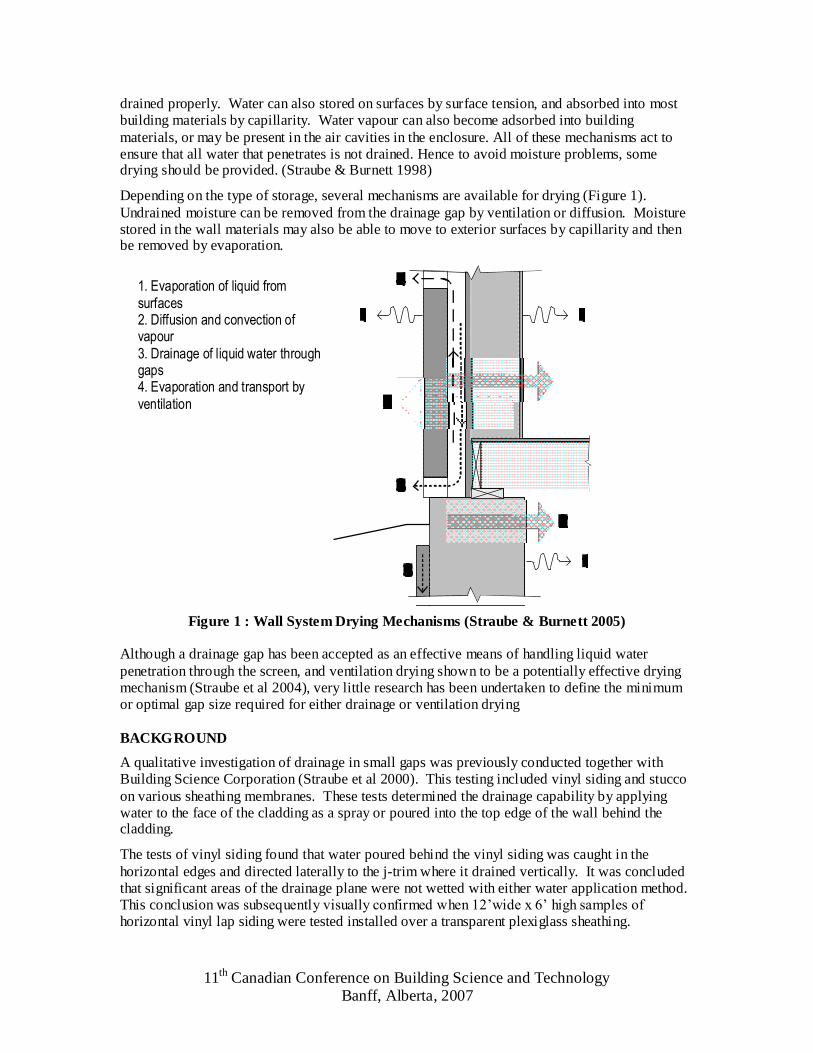
Depending on the type of storage, several mechanisms are available for drying (Figure 1). Undrained moisture can be removed from the drainage gap by ventilation or diffusion. Moisture stored in the wall materials may also be able to move to exterior surfaces by capillarity and then be removed by evaporation.
Figure 1 : Wall System Drying Mechanisms (Straube & Burnett 2005)
Although a drainage gap has been accepted as an effective means of handling liquid water penetration through the screen, and ventilation drying shown to be a potentially effective drying mechanism (Straube et al 2004), very little research has been undertaken to define the minimum or optimal gap size required for either drainage or ventilation drying
BACKGROUND
A qualitative investigation of drainage in small gaps was previously conducted together with Building Science Corporation (Straube et al 2000). This testing included vinyl siding and stucco on various sheathing membranes. These tests determined the drainage capability by applying water to the face of the cladding as a spray or poured into the top edge of the wall behind the cladding.
The tests of vinyl siding found that water poured behind the vinyl siding was caught in the horizontal edges and directed laterally to the j-trim where it drained vertically. It was concluded that significant areas of the drainage plane were not wetted with either water application method. This conclusion was subsequently visually confirmed when 12’wide x 6’ high samples of horizontal vinyl lap siding were tested installed over a transparent plexiglass sheathing.
1. Evaporation of liquid from surfaces 2. Diffusion and convection of vapour 3. Drainage of liquid water through gaps 4. Evaporation and transport by ventilation

11th Canadian Conference on Building Science and Technology Banff, Alberta, 2007
The stucco wall assemblies were tested by pouring two litres of water behind the cladding. It was found that single layers of sheathing membrane bonded to the stucco and hence did not allow good drainage. By adding an extra layer of sheathing membrane as a bond break, water drained significantly faster. Even corrugated housewrap performed poorly when installed directly behind stucco because of the bond formed, but the corrugated housewrap in combination with felt paper was the best performing system tested.
We previously investigated ventilation drying in wood frame walls together with Penn State University and Oak Ridge National Labs (Schumacher et al 2003). An experimental wall was wetted and then dried while resting on a load cell to constantly measure the changes in mass of the wall. A counterbalance was used to offset the dead load on the load cell and thereby greatly increasing the precision of the readings.
To better understand the drainage capacity required of a drainage gap, a driving rain and wind analysis was conducted using extensive Canadian weather data (Straube & Schumacher 2006). It was found that the driving rain deposition rate for an average driving rain event for all monitored Canadian cities was 0.7 mm/hr (0.012 l/m2-min). For the extreme rain event, the 1% rain event (is exceeded 1% of the hours during rain) was chosen. The limiting values for the 1% driving rain event ranged from 3.0 mm/hr (0.05 l/m2-min) and 10.4 mm/hr (0.17 l/m2-min) depending on the city studied
The calculated driving rain rates and wind pressures were compared to two water penetration test standards: ASTM E514 Standard Test Method for Water Penetration and Leakage Through Masonry, ASTM E331 Standard Test Method for Water Penetration of Exterior Windows, Skylights, Doors, and Curtain Walls by Uniform Static Air Pressure Difference (Table 1). It can be seen that the testing standards imposed loads that are many times, often orders of magnitude, higher than even the most extreme rain event recorded in Canadian data.
Table 1 : Comparison of Rain Data Analysis to Leakage Test Standards
Application Rate (l/m2-min)
Pressure Difference (Pa)
ASTM E514 2.3 500 ASTM E331 3.4 137
Calc. Average Driving Rain 0.012 10 (at 10 m) Calc. 1% Driving Rain 0.170 84 (at 10 m)
Quantitative drainage and drying testing of EIFS on wood sheathing is also being conducted at Forintek Canada Corp. This testing was conducted according to a CCMC Technical Guide currently under review (Onysko 2006). The standard states, at the time this research was conducted, that the moisture retained at the end of a wetting/drainage phase lasting two hours to be no greater than 30 g/m2 and that the retained moisture after two full days of drying be no greater than 15 g/m2. The testing apparatus used by Forintek was nearly identical to the apparatus previously used by Schumacher et al (2003) at Penn State University (PSU). Approximately 8 liters of water was applied from a trough into the drainage space over the space of one hour. There was a significant difference in stored moisture between identically constructed walls (126-254 g/m2). It was uncertain from the report why this large difference occurred. During the drying phase of the testing, the backs of the wall cavities were left open to the laboratory, which may have influenced the drying ability, and overestimated the drying potential of the cladding system (Onysko 2006).

11th Canadian Conference on Building Science and Technology Banff, Alberta, 2007
OBJECTIVE
A research program was developed with two main objectives. The first objective was to determine the minimum gap width necessary for drainage. The other main objective was to develop a repeatable and defendable test method to characterize, drainage, storage and drying for drained wall systems. Assessing the influence of small gaps to ventilation drying was a secondary objective.
METHODOLOGY
From the previous research at PSU and Forintek, it was clear that the temperature and RH conditions surrounding the test apparatus needed to be tightly controlled to avoid variations due to adsorption and to ensure repeatable drying rates. Hence, tests were conducted in the Building Engineering Group laboratory which is operated at target conditions of 20˚C and 50%.
A test apparatus capable of accepting walls weighing several hundred kg and resolving mass changes to several grams was constructed. The load cell was installed in tension to remove all lateral forces (Figure 2). Before each test, calibration weights were added to confirm the linear response of the system, and to calibrate its output. The amount of water drained from the system could also be measured gravimetrically using this apparatus.
DRAINAGE TEST PROTOCOL
Based on ASTM E2273, we originally chose 8 liters of water as the volume to be poured behind the cladding in two doses. However, during the first tests it was noted that the amount stored in the wall reached almost the same maximum value even if a dose much smaller than 4 liters was used. In subsequent testing we chose to impose two doses of 1.5 liters for a 4’ wide x 7’ tall wall system, and two doses of 1.0 liter for smaller 3’x6’ specimens. In all cases drainage stopped a few minutes after water was no longer added to the drainage gap. Note that the maximum stored is defined here as the short-term storage quantity. Many materials can absorb much more moisture if the wetting is continued for much longer than the 1 minute test. However, the test protocol is not intended to measure the capillary uptake rates and storage capacity of materials, but the short-term pseudo-instantaneous storage of draining water.
Figure 3 shows a typical drainage and storage curve. The blue line is the mass of the test wall, the pink line is the mass of the drained water into the storage bucket, and the green line is the addition of the two, or the total water added to the system. The values used to characterize wall system performance were A, the initial or primary storage, and B, the final or secondary storage.
The final drainage test protocol chosen is:
1. Perform a calibration check of the load cells (a known weight is applied to the test wall and the reading from the balance is confirmed)
2. Pour a 1 or 1.5 litre dose into the drainage cavity over one minute a 3. Wait fifteen minutes to allow drainage to finish 4. Pour the second dose into the drainage cavity over one minute a 5. Wait fifteen minutes for drainage to finish 6. Begin drying test (if any)
The entire drainage test requires less than about one hour to complete.
a 1.0 Litre was used on wall specimens measuring 3’x 6’

11th Canadian Conference on Building Science and Technology Banff, Alberta, 2007
Figure 2: Wall Balance Testing Apparatus
DRYING TEST PROTOCOL
Two protocols were developed to investigate drying. To determine the effect of wind induced ventilation drying, two tests were conducted on the same specimen, one without any drying assistance, and one with a fluctuating average 1 Pa pressure between the top and bottom of the cladding imposed by a fan. The 1 Pa pressure difference was measured with a precision digital averaging low-pressure manometer. This pressure was chosen as the lower quartile of the pressures measured on one-storey high walls installed at grade (Straube & Burnett 1995) The mass of the wall specimen was measured continuously over a period of 6 to 7 days. This allowed for a drainage test and drying test to be completed within a week.
The second drying test protocol used heat lamps to simulate solar heating. It is well known that even a limited amount of heating can significantly increase the drying of materials and systems. Limited heating of about 10 ºC was applied for 8 hours per day for a one week drying test. Numerous tests have been conducted with the application of both simulated solar heating and wind-induced ventilation.
The drying curves for all of the drying tests had a similar shape which included a preliminary and secondary drying curve. The preliminary drying period, usually 6 to 20 hours long, was steep and

11th Canadian Conference on Building Science and Technology Banff, Alberta, 2007
was controlled by the amount of free water and near-surface absorption that could be easily and quickly evaporated. The secondary drying period was much slower and is controlled by the quantity and type of water distribution. Water stored deep inside a material must first be transported to the surface for evaporation, and this limits the drying rate.
Figure 3 : Typical Gravimetric Drainage Testing Results
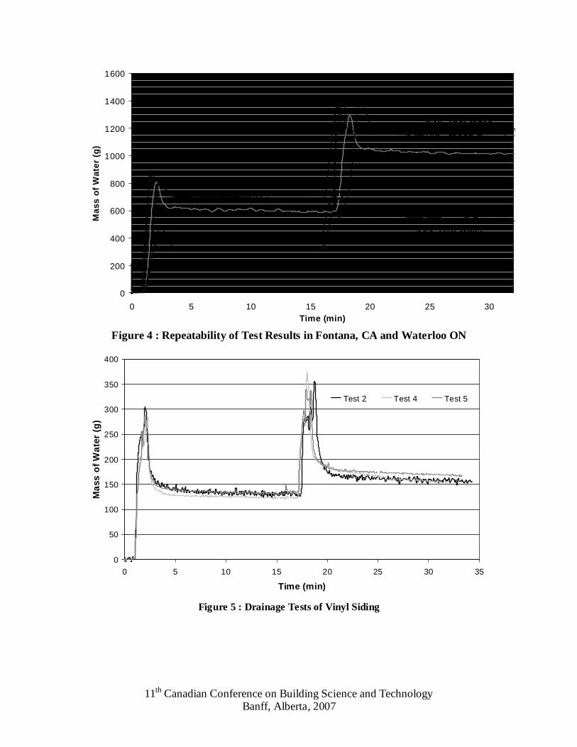
Several drainage tests were conducted on fiber cement sheet applied over housewrap directly on framing (i.e. no sheathing) to demonstrate repeatability. These walls were tested in Waterloo, Ontario as well as independently on a similar balance apparatus in a laboratory in Fontana, California. Six drainage tests conducted on 4’x8’ wall panels, three in each location, and there were two drainage tests conducted on a 4’x4’ test wall, one in each location. With the exception of the first test conducted in Fontana, before the load cell was properly calibrated, the results, shown in Figure 4, demonstrate that the test protocol is repeatable. Another comparison was conducted with vinyl cladding. This showed that even with a discontinuous drainage gap the results were repeatable (Figure 5).
Repeatable drying results are more difficult to illustrate than repeatable drainage results because of the length of time required for a drying test, and the influence of laboratory conditions on drying. Figure 6 is an example of the same wall specimen dried twice under similar conditions. The drying curve demonstrates good repeatability.
11th Canadian Conference on Building Science and Technology Banff, Alberta, 2007
0
200
400
600
800
1000
1200
1400
1600
0 5 10 15 20 25 30Time (min)
Ma
ss
of
Wa
ter
(g)
4'x8' Test Walls
4'x4' Test Walls
Figure 4 : Repeatability of Test Results in Fontana, CA and Waterloo ON
0
50
100
150
200
250
300
350
400
0 5 10 15 20 25 30 35
Time (min)
Ma
ss o
f W
ate
r (g
)
Test 2 Test 4 Test 5
Figure 5 : Drainage Tests of Vinyl Siding

11th Canadian Conference on Building Science and Technology Banff, Alberta, 2007
0
50
100
150
200
250
0 20 40 60 80 100 120
Time (hours)
Ma
ss
of
Wa
ter
(g) EIFS-1 Test 6 EIFS-1 Test 5
Figure 6 : Repeatability of Drying Curves for a drained EIFS wall
ADHOC TESTING
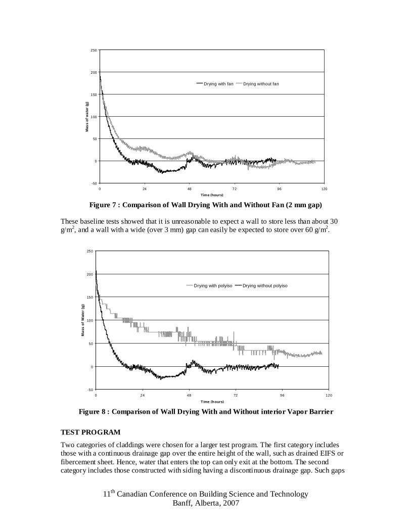
The results in Figure 7 show a difference in the drying curve between the two types of drying tests on an EIFS wall with a 2 mm gap. It can be seen that even with a small 1 Pa pressure and small gap, ventilation can have a notable effect on drying.
Another test was conducted to investigate the effect of sealing the stud space on drying. An air and vapour barrier comprised of a foil-faced polyisocyanurate board taped to the back (“inside”) of the sheathing and metal studs with aluminum tape. Figure 8 shows that the time to dry decreased significantly when the wall system could dry in both the inward and outward directions. In real walls, this inward drying moisture may be stored in the stud cavity.
To determine the absolute minimum amount of moisture stored after drainage stops, several drainage tests of smooth non-absorptive materials were conducted. One test consisted of applying a fine spray of water onto a sheet of polyethylene while it was hung vertically. Three spray tests using the polyethylene sheet returned an average storage amount of 35 g/m2. The same testing was conducted on a vertical acrylic sheet and the storage amount found to be approximately 65 g/m2. Athough both materials appear smooth and are hydrophobic, we hypothesize that the increased hydrophobicity of the polyethylene sheet resulted in less storage.
Another test was conducted using a wall built with a small gap between two sheets of acrylic sheet. The gap was maintained by a series of washers, approximately 1mm thick. This test was conducted twice. It was found that the gap stored 23 and 25 g/m2. The amount of water stored in the drainage gap was therefore significantly less than the amount of water stored on a single sheet of acylic. It is hypothesized that this is because the 1mm gap did not allow beads of water to form on the surface. This test provides the surprising result that, it may be possible for a very small drainage gap to store less water than a large drainage space. The same might be true of a space filled with a drainage mat or fabric, but requires more testing and research.
11th Canadian Conference on Building Science and Technology Banff, Alberta, 2007
-50
0
50
100
150
200
250
0 24 48 72 96 120
Time (hours)
Mas
s o
f w
ate
r (g
)Drying with fan Drying without fan
Figure 7 : Comparison of Wall Drying With and Without Fan (2 mm gap)
These baseline tests showed that it is unreasonable to expect a wall to store less than about 30 g/m2, and a wall with a wide (over 3 mm) gap can easily be expected to store over 60 g/m2.
-50
0
50
100
150
200
250
0 24 48 72 96 120
Time (hours)
Ma
ss o
f W
ate
r (g
)
Drying with polyiso Drying without polyiso
Figure 8 : Comparison of Wall Drying With and Without interior Vapor Barrier
TEST PROGRAM
Two categories of claddings were chosen for a larger test program. The first category includes those with a continuous drainage gap over the entire height of the wall, such as drained EIFS or fibercement sheet. Hence, water that enters the top can only exit at the bottom. The second category includes those constructed with siding having a discontinuous drainage gap. Such gaps

11th Canadian Conference on Building Science and Technology Banff, Alberta, 2007
are designed to drain over the entire surface area of the wall so drainage will not only occur at the bottom such as vinyl siding or lapboard siding.
The three main variables examined during testing are the drainage gap width, the drainage plane material, and the cladding material. The drainage plane material and cladding generally form the surfaces of the drainage gap. The drainage gap materials are shown in Tables 2 and 3 and the drainage gap width is shown as the equivalent gap determined from airflow testing. In some cases, the wall sizes for the drainage testing were 3’ x 7’ frames (instead of 4’x8’) with a 3’ x 6’ test area so they would be easier to handle in the lab. Storage amounts were always reported in g/m2 to provide normalized values. All other aspects of the previously reported test procedure were kept the same.
One of the main objectives of testing was to determine the minimum gap width required for drainage. Several of the walls had very small gaps. To measure these gaps, an air pressure versus flow test was used, and the results converted to an equivalent clear air space dimension. All of the gap widths reported in this paper are based on this equivalent measure. Some of the systems, such as two layers of building paper, returned values of less than 1 mm.
TEST RESULTS: CONTINUOUS GAPS
The most general, and important, result of the testing is that fast drainage occurred in all of the walls with a continuous gap even if the gap is very small (approx 1 mm). For all of the continuous drainage gap testing the storage results are shown below in Test Results: Siding
An investigation into the drainage ability of siding products was conducted to see how various common siding products differ with respect to drainage, storage and drying. The siding products tested included vinyl siding, fiber cement siding, a manufactured and prefinished wood product, and unpainted cedar siding, installed on either SBPO or #15 felt.
Table 2. No correlation between storage quantity and gap size was detected, although absorbent materials lining the gap obviously increased the amount of moisture storage. Even the wall with direct applied stucco over two layers of building paper with a barely measurable gap (<1 mm), drained all of the test water. A complete analysis of drainage results can be found in Smegal (2006).
The drainage rates measured were compared with the extreme 1% hourly rain deposition rates predicted in the driving rain study described earlier. It was found that even small gaps (1 mm) drained more water than would ever be expected in drainage gaps (i.e., drainage rates exceeded 1 liter/minute per meter width).
TEST RESULTS: SIDING
An investigation into the drainage ability of siding products was conducted to see how various common siding products differ with respect to drainage, storage and drying. The siding products tested included vinyl siding, fiber cement siding, a manufactured and prefinished wood product, and unpainted cedar siding, installed on either SBPO or #15 felt.

11th Canadian Conference on Building Science and Technology Banff, Alberta, 2007
Table 2 : Sheet Product Drainage Testing Results
Gap (g/m2) (g/m2)System Test Drainage Plane Cladding (mm) Gap primary secondary
EIFS-1 Test 3 DensGlas Gold EPS with ext. finish >1 formed by adhesive 88 77Test 4 DensGlas Gold EPS with ext. finish >1 formed by adhesive 85 81
EIFS-2 Test 1 trowel applied EPS with ext. finish 1.5 formed by adhesive 133 160
EIFS-3 Test 1 trowel applied EPS with ext. finish <1 1/4" by 1" grooves 186 200Test 2 trowel applied EPS with ext. finish <1 1/4" by 1" grooves 194 208
EIFS-4 Test 2 trowel applied EPS with ext. finish 3 formed by adhesive 108 119Test 3 trowel applied EPS with ext. finish 3 formed by adhesive 111 135
EIFS-5 Test 1 trowel applied EPS with ext. finish 2 formed by adhesive 96 132Test 2 trowel applied EPS with ext. finish 2 formed by adhesive 90 118Test 3 trowel applied EPS with ext. finish 2 formed by adhesive 102 144
EIFS-6 Test 3 Tyvek EPS with cement coating horiz and vert grooves 48 75Test 4 Tyvek EPS with cement coating horiz and vert grooves 45 69Test 5 Tyvek EPS with cement coating horiz and vert grooves 50 80
Stucco-1 Test 2 2 layers #15 felt 3/4" Cement Stucco <1 2 layers #15 felt 212 300Test 3 2 layers #15 felt 3/4" Cement Stucco <1 2 layers #15 felt 262 375
Stucco-2 Test 1 2 layers #15 felt 3/4" Cement Stucco 9 19 mm strapping 189 245Test 2 2 layers #15 felt 3/4" Cement Stucco 9 19 mm strapping 242 371
AGM-1 Test 1 Air Gap Membrane Vinyl siding 3 141 173AGM-1 Test 2 Air Gap Membrane Vinyl siding 3 142 167
Felt-1 Test 1 #15 paper Vinyl siding 153 182Felt-1 Test 2 #15 Paper Vinyl siding 161 203
Towel-1 Test 1 Air Gap Membrane fiber cement (paper towels) 3 574 1005Towel-2 Test 1 #15 Paper fiber cement (paper towels) <1 583 984
FCSheet-1 Test 1 Tyvek Fiber cement Sheet 4'x8' Waterloo 223 378FCSheet-1 Test 2 Tyvek Fiber cement Sheet 4'x8' Waterloo 232 393FCSheet-1 Test 3 Tyvek Fiber cement Sheet 4'x8' Waterloo 245 411FCSheet-2 Test 1 Tyvek Fiber cement Sheet 4'x8' Fontana 201 344FCSheet-2 Test 2 Tyvek Fiber cement Sheet 4'x8' Fontana 228 382FCSheet-2 Test 3 Tyvek Fiber cement Sheet 4'x8' Fontana 229 400
FCSheet-3 Test 1 Tyvek Fiber cement Sheet 4'x4' Waterloo 218 353FCSheet-4 Test 1 Tyvek Fiber cement Sheet 4'x4' Fontana 204 364
FCSheet-5 Test 1 Tyvek Fiber cement Sheet 2'x4' Fontana 199 335 The siding analysis provided some challenges since the drainage gap is discontinuous. During the first drainage test, it appeared as if the majority of the water was draining over the front of the cladding. Dye was added to the water to identify the drainage paths for the water. Using this method it was shown that almost all of the water was removed from the drainage gap after only two rows of lap siding. This means that if the front of the siding is not sealed between the planks, than the cladding is inherently well drained. Installing siding products on strapping will not noticeably increase the drainage ability of the siding. However, strapping will allow ventilation drying.
The siding storage results are shown below in Table 3. It can be seen that the cedar siding stored the largest amount of water. This is not surprising since the cedar siding was untreated on all sides. The siding was left untreated so that it may be possible to make future comparisons between treated and untreated cedar siding. The second highest storage value was achieved by vinyl siding. Vinyl siding is non absorptive but has many channels where water can collect. Fiber cement siding and manufactured wood (both factory finished with non-absorptive coatings

11th Canadian Conference on Building Science and Technology Banff, Alberta, 2007
on their face) stored the least amount of water. Since the majority of water was on the exterior of the siding, less water was absorbed and stored by these products.
Table 3 : Siding Product Drainage Testing Results
(g/m2) (g/m2)System Test Drainage Plane Cladding primary secondary
Vinyl SidingVinyl-1 Test 4 Tyvek Vinyl siding 124 155Vinyl-1 Test 2 Tyvek Vinyl siding 130 156Vinyl-1 Test 5 Tyvek Vinyl siding 135 168
Vinyl-2 Test 11 #15 Felt Paper Vinyl siding 146 172Vinyl-2 Test 9 #15 Felt Paper Vinyl siding 155 182Vinyl-2 Test 7 #15 Felt Paper Vinyl siding 152 189
Fiber Cement SidingFCSiding-1 Test 10 Tyvek Back primed fiber cement 93 129FCSiding-1 Test 8 Tyvek Back primed fiber cement 96 126FCSiding-1 Test 6 Tyvek Back primed fiber cement 92 135
FCSiding-2 Test 16 #15 Felt Paper Back primed fiber cement 99 139FCSiding-2 Test 14 #15 Felt Paper Back primed fiber cement 90 141
Cedar SidingCedar-1 Test 13 Tyvek Cedar Siding Untreated 203 330Cedar-1 Test 12 Tyvek Cedar Siding Untreated 192 333
LP SmartsideLP-1 Test 17 Tyvek LP Smartside 87 122LP-1 Test 15 Tyvek LP Smartside 84 111
DRYING TEST RESULTS
Ventilation drying tests were conducted on a model wall system. Both surfaces of the drainage gap were acrylic sheet and the gap stored 24 g/m2 of water. As the sheet is vapor impermeable, essentially all drying is via the gap. It can be seen that even with a 1 mm gap ventilation drying can occur (Figure 9).
One of the objectives of the drying tests was to determine the minimum size of gap needed for ventilation drying of a wall system. The first ventilation drying comparison was conducted on a drained EIFS wall with an equivalent gap width of approximately 2 mm. Applying a 1 Pa pressure difference for ventilation was shown to have an effect on the drying of the wall previously shown in Figure 7.

11th Canadian Conference on Building Science and Technology Banff, Alberta, 2007
0
5
10
15
20
25
30
35
40
0 10 20 30 40 50 60 70 80
Time (hours)
Mas
s o
f Wat
er (g
)
Test B - no fan
Test C - fan
Figure 9 : Ventilation Drying of a 1 mm Wide Drainage Gap
Ventilation drying was also compared stucco test walls. A 1 Pa pressure difference was applied to both the direct applied stucco and the stucco installed on strapping with an equivalent gap width of 9 mm. It can be seen in Figure 10 that the preliminary drying curve for Stucco-2 is much steeper coinciding with ventilation drying of the cavity. After the preliminary drying, the slopes become very similar as the rate limiting step becomes the transport of moisture to the surfaces rather than the rate of removal by ventilation.
0
200
400
600
800
1000
1200
0 24 48 72 96 120
Time (hours)
Mas
s o
f W
ater
(g
)
Stucco-2 Stucco-1
Figure 10: Comparison of Stucco Wall Drying With and Without Ventilation

11th Canadian Conference on Building Science and Technology Banff, Alberta, 2007
CONCLUSIONS/RECOMMENDATIONS
The current testing standards for leakage of walls and windows use water application rates orders of magnitude higher than actual recorded rain events. By using such extreme water application rates, some construction techniques may not be acceptable when in reality they would perform adequately.
A test apparatus and protocols were developed to precisely measure the amount of water retained after drainage. The rate of drying under carefully controlled conditions could also be assessed. The repeatability of the developed protocol and test apparatus was demonstrated by multiple tests in two different locations.
Testing found that even a small gap (approx 1 mm) will drain water at a rate considerably greater than it is expected behind claddings even in extreme conditions. For example, the measured drainage rate of a gap of about 1.0 mm wide was found to be in excess of 1.1 litre/minute-meter width, more than the extreme driving rain intensity for the worst climate in Canada.
Walls with lap siding tended to drain water out onto the face of the plank immediately below the plank at which the water was injected.
During testing of non absorptive materials, a suspended polyethylene sheet consistently stored 35 g/m2 and a single acrylic sheet of plexiglas stored 65 g/m2. The drainage tests in the plexiglas wall resulted in storage amounts of approximately 24 g/m2 showing that in some special cases, a very small gap will actually store less water than a large drainage gap.
A 10 mm gap behind drained claddings (as required in the new National Building Code of Canada) is not required to ensure drainage. However, a 10 mm gap may be sufficient to provide useful ventilation drying behind some claddings in some climates if desired. In practice, drainage gaps larger than 1 mm are provided to accommodate construction tolerances. However, some products (such as drainage mats, factory grooved or dimpled insulations) are designed to ensure that a minimum drainage gap is provided, and hence, based on physics, should not require a 10 mm gap.
To build on the knowledge gained in this research more investigation is needed to analyze the role of surface contact angles and moisture stored on non absorptive surfaces. Although it was shown that ventilation can be important for drying even in small air spaces, a more detailed study of ventilation drying should be conducted to determine the optimum gap width for ventilation drying.
Non-absorptive enclosure materials behaved much more predictably during storage and drying than similar walls with absorptive (hygroscopic) materials. Further analysis may reveal methods to more accurately predict the performance of absorptive wall system materials. Other future work will focus on the correlation of hygrothermal modeling with the storage and drying results.
REFERENCES Ritchie, T. Cavity Walls. Canadian Building Digest 21, National Research Council of Canada, Ottawa, 1961. Lacasse, M.A.; O'Connor, T.J.; Nunes, S.; Beaulieu, P, Report from Task 6 of MEWS Project : Experimental Assessment of Water Penetration and Entry into Wood-Frame Wall Specimens - Final Report, Institute for Research in Construction, Feb. 2003. Smegal, J., Drainage and Drying of Small Gaps in Wall Systems. MASc dissertation, Civil Engineering Department, University of Waterloo, 2006. Straube J.F., and E.F.P. Burnett , Building Science for Building Enclosures, Building Science Press, Westford, Massachusetts, 2005.

11th Canadian Conference on Building Science and Technology Banff, Alberta, 2007
Straube, J.F., J. Lstiburek, A.N. Karagiozis, and C.J. Schumacher. Preliminary Investigation of Drainage in Full-Scale Walls Clad with Stucco and Horizontal Vinyl Siding. Building Science Corporation, Boston, 2000. Schumacher, C.J., Xing Shi, D. Davidovich, E.F.P. Burnett, J.F. Straube, “Ventilation Drying in Wall Systems”, Proc. of the Second International Conference on Building Physics, 14-19 September, 2003, Leuven, Belgium, pp 479-486. Straube, J.F., and Schumacher, C.J., Driving Rain Loads for Canadian Building Design. Report for CMHC by Univ. of Waterloo, Ottawa, 2006. MHC. 2007. Part 3 - Drainage Testing of EIFS Wall Systems. one of a series of 8 reports by Forintek Canada Corp. on Drainage and Retention of Water by Cladding Systems. Straube, J.F. and Burnett, E.F.P., "Drainage, Ventilation Drying, and Enclosure Performance", Proc. of Thermal Performance of Building EnvelopesVII, Clearwater Beach Florida, December 4-7, 1998, pp. 189-198. Straube, J.F., VanStraaten, R., Burnett, E.F.P., “Field Studies of Ventilation Drying”, Proc. of Performance of Exterior Envelopes of Whole Building IX, Clearwater Beach Florida, December, 2004. Straube, J.F. and Burnett, E.F.P., Vents, Ventilation, and Pressure Moderation. Building Engineering Group Report for Canada Mortgage and Housing, Ottawa, December, 1995. Onysko, Don. Personal communication, various, 2006.