the search for perfect perforations - oilfield …/media/files/resources/mearr/num7/... · the...
TRANSCRIPT
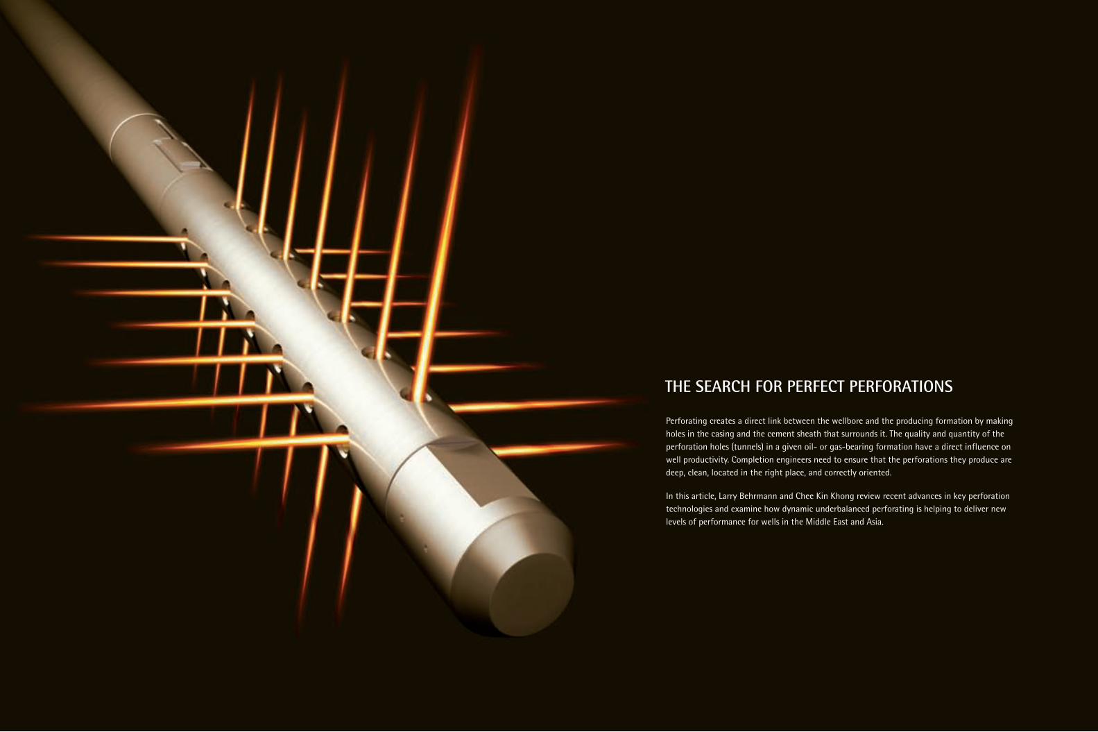
THE SEARCH FOR PERFECT PERFORATIONS
Perforating creates a direct link between the wellbore and the producing formation by makingholes in the casing and the cement sheath that surrounds it. The quality and quantity of theperforation holes (tunnels) in a given oil- or gas-bearing formation have a direct influence onwell productivity. Completion engineers need to ensure that the perforations they produce aredeep, clean, located in the right place, and correctly oriented.
In this article, Larry Behrmann and Chee Kin Khong review recent advances in key perforationtechnologies and examine how dynamic underbalanced perforating is helping to deliver newlevels of performance for wells in the Middle East and Asia.
52 Middle East & Asia Reservoir ReviewNumber 7, 2006
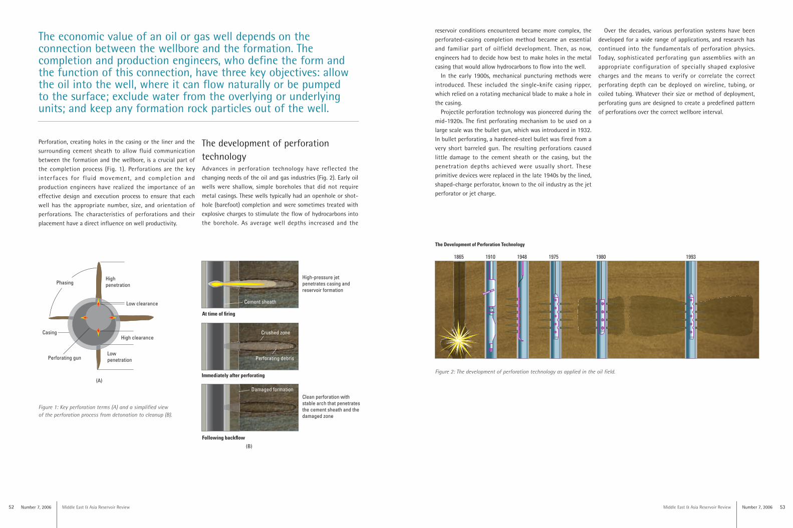
Perforation, creating holes in the casing or the liner and thesurrounding cement sheath to allow fluid communicationbetween the formation and the wellbore, is a crucial part ofthe completion process (Fig. 1). Perforations are the keyinterfaces for fluid movement, and completion andproduction engineers have realized the importance of aneffective design and execution process to ensure that eachwell has the appropriate number, size, and orientation ofperforations. The characteristics of perforations and theirplacement have a direct influence on well productivity.
Middle East & Asia Reservoir Review Number 7, 2006 53
Highpenetration
Low clearance
High clearance
LowpenetrationPerforating gun
Casing
Phasing
At time of firing
Immediately after perforating
Following backflow
High-pressure jetpenetrates casing and reservoir formation
Cement sheath
Crushed zone
Perforating debris
Clean perforation withstable arch that penetratesthe cement sheath and thedamaged zone
Damaged formation
fig01_perforating_m7
(A)
(B)
Figure 1: Key perforation terms (A) and a simplified viewof the perforation process from detonation to cleanup (B).
The economic value of an oil or gas well depends on theconnection between the wellbore and the formation. Thecompletion and production engineers, who define the form andthe function of this connection, have three key objectives: allowthe oil into the well, where it can flow naturally or be pumpedto the surface; exclude water from the overlying or underlyingunits; and keep any formation rock particles out of the well.
reservoir conditions encountered became more complex, theperforated-casing completion method became an essentialand familiar part of oilfield development. Then, as now,engineers had to decide how best to make holes in the metalcasing that would allow hydrocarbons to flow into the well.
In the early 1900s, mechanical puncturing methods wereintroduced. These included the single-knife casing ripper,which relied on a rotating mechanical blade to make a hole inthe casing.
Projectile perforation technology was pioneered during themid-1920s. The first perforating mechanism to be used on alarge scale was the bullet gun, which was introduced in 1932.In bullet perforating, a hardened-steel bullet was fired from avery short barreled gun. The resulting perforations causedlittle damage to the cement sheath or the casing, but thepenetration depths achieved were usually short. Theseprimitive devices were replaced in the late 1940s by the lined,shaped-charge perforator, known to the oil industry as the jetperforator or jet charge.
Over the decades, various perforation systems have beendeveloped for a wide range of applications, and research hascontinued into the fundamentals of perforation physics.Today, sophisticated perforating gun assemblies with anappropriate configuration of specially shaped explosivecharges and the means to verify or correlate the correctperforating depth can be deployed on wireline, tubing, orcoiled tubing. Whatever their size or method of deployment,perforating guns are designed to create a predefined patternof perforations over the correct wellbore interval.
The development of perforationtechnologyAdvances in perforation technology have reflected thechanging needs of the oil and gas industries (Fig. 2). Early oilwells were shallow, simple boreholes that did not requiremetal casings. These wells typically had an openhole or shot-hole (barefoot) completion and were sometimes treated withexplosive charges to stimulate the flow of hydrocarbons intothe borehole. As average well depths increased and the
1865 1910 1948 1975 1980 1993
The Development of Perforation Technology
Figure 2: The development of perforation technology as applied in the oil field.
Middle East & Asia Reservoir Review Number 7, 2006 5554 Middle East & Asia Reservoir ReviewNumber 7, 2006
Shaped charges have four basicelements: primer, main explosive,conical liner, and case. The conicalcavity with its metal liner helps tomaximize the penetration through steelcasing, cement, and rock (Fig. 3). As acharge detonates, the liner collapses to
form a high-velocity jet of fluidizedmetal particles. Perforating shock wavesand high-impact pressure shatter therock to break down the intergranularcements and sever the bonds that holdthe clay particles together. This processcreates a low-permeability crushed
Shaped charges
zone in the formation around theperforation tunnels. Perforatingdamages the in situ permeability bycrushing the formation material andreducing the pore throat’s dimensions.
Shaped charges are used in the oil,gas, and other industries to pierce metal,
Case
Conical liner
Detonating cord
Shaped Charge
Explosive Cavity Effects
Primer
Main explosivecharge
Explosive Steel targetMetallic liner
Lined cavityeffect
Flat-end
Unlinedcavity effect
Casing
Gun body
Detonatingcord
Charge DetonationCharge Detonation
5
Time, us
25
40
50
70
0 2-2-4-6 4 6 8 10 12 14 16 18 20
Distance, cm
6
Tim
e,us
24
40
50
70
100
concrete, and other solids. They sever thetargets by jet cutting. Shaped chargeshave special housings that are designedto create a cavity or a void between theexplosive material and the target wall. By employing a phenomenon known asthe Monroe effect, the shock waveproduced at detonation accelerates anddeforms the shaped housing into a high-velocity (7,300–8,200-m/s) jet within thevoid space.
These jets can cut through steeltargets of varying thicknesses,depending on the void shape and thestandoff distance to the target wall.Because the cutting efficiency ofshaped charges is much greater thanthat of bulk charges, they can oftenreduce the net weight of explosiveneeded to sever similarly sized targets.
Conical-shaped charges (CSC) createconical cavities for round holes anddeep penetration into the target.Industry’s primary use of CSCs is inperforating guns; multiple CSCassemblies placed down boreholes anddetonated to penetrate through casingand into the surrounding geologicalstrata for the extraction ofhydrocarbons. The use of steel forcharge cases instead of zinc eliminatesthe decrease in formation productivityand the damage to completioncomponents associated with thedetonation by-products from zinccharges and reduces the cost of thecompletion fluids required. Shapedcharges are designed and arranged tooptimize orientation and are deployedon a tubing-conveyed perforating
system to provide an effective solutionfor perforating and increasing theproductivity in long horizontal intervals.
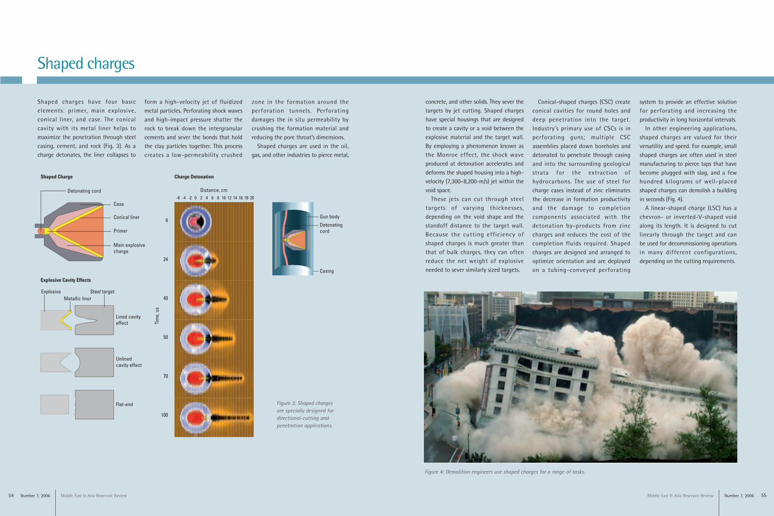
In other engineering applications,shaped charges are valued for theirversatility and speed. For example, smallshaped charges are often used in steelmanufacturing to pierce taps that havebecome plugged with slag, and a fewhundred kilograms of well-placedshaped charges can demolish a buildingin seconds (Fig. 4).
A linear-shaped charge (LSC) has achevron- or inverted-V-shaped voidalong its length. It is designed to cutlinearly through the target and can be used for decommissioning operations in many different configurations,depending on the cutting requirements.
Figure 4: Demolition engineers use shaped charges for a range of tasks.
Figure 3: Shaped chargesare specially designed fordirectional-cutting andpenetration applications.
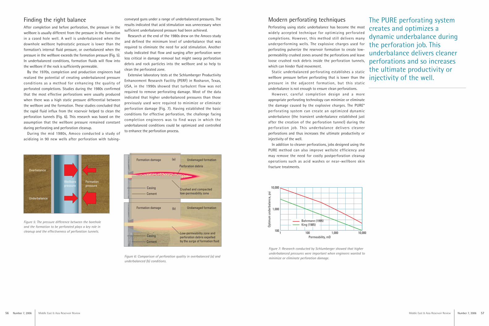
10,000
1,000
10010,0001,000100
Permeability, mD1
Optim
umun
derb
alan
ce,p
si
Behrmann (1995)King (1985)
56 Middle East & Asia Reservoir ReviewNumber 7, 2006 Middle East & Asia Reservoir Review Number 7, 2006 57
Finding the right balanceAfter completion and before perforation, the pressure in thewellbore is usually different from the pressure in the formationin a cased hole well. A well is underbalanced when thedownhole wellbore hydrostatic pressure is lower than theformation’s internal fluid pressure, or overbalanced when thepressure in the wellbore exceeds the formation pressure (Fig. 5).In underbalanced conditions, formation fluids will flow intothe wellbore if the rock is sufficiently permeable.
By the 1970s, completion and production engineers hadrealized the potential of creating underbalanced pressureconditions as a method for enhancing the quality ofperforated completions. Studies during the 1980s confirmedthat the most effective perforations were usually producedwhen there was a high static pressure differential betweenthe wellbore and the formation. These studies concluded thatthe rapid fluid influx from the reservoir helped to clean theperforation tunnels (Fig. 6). This research was based on theassumption that the wellbore pressure remained constantduring perforating and perforation cleanup.
During the mid 1980s, Amoco conducted a study ofacidizing in 90 new wells after perforation with tubing-
Modern perforating techniquesPerforating using static underbalance has become the mostwidely accepted technique for optimizing perforatedcompletions. However, this method still delivers manyunderperforming wells. The explosive charges used forperforating pulverize the reservoir formation to create low-permeability crushed zones around the perforations and leaveloose crushed rock debris inside the perforation tunnels,which can hinder fluid movement.
Static underbalanced perforating establishes a staticwellbore pressure before perforating that is lower than thepressure in the adjacent formation, but this staticunderbalance is not enough to ensure clean perforations.
However, careful completion design and a moreappropriate perforating technology can minimize or eliminatethe damage caused by the explosive charges. The PURE*perforating system can create an optimized dynamicunderbalance (the transient underbalance established justafter the creation of the perforation tunnel) during theperforation job. This underbalance delivers cleanerperforations and thus increases the ultimate productivity orinjectivity of the well.
In addition to cleaner perforations, jobs designed using thePURE method can also improve wellsite efficiency and may remove the need for costly postperforation cleanupoperations such as acid washes or near-wellbore skinfracture treatments.
Figure 6: Comparison of perforation quality in overbalanced (a) andunderbalanced (b) conditions.
conveyed guns under a range of underbalanced pressures. Theresults indicated that acid stimulation was unnecessary whensufficient underbalanced pressure had been achieved.
Research at the end of the 1980s drew on the Amoco studyand defined the minimum level of underbalance that wasrequired to eliminate the need for acid stimulation. Anotherstudy indicated that flow and surging after perforation wereless critical in damage removal but might sweep perforationdebris and rock particles into the wellbore and so help toclean the perforated zone.
Extensive laboratory tests at the Schlumberger ProductivityEnhancement Research Facility (PERF) in Rosharon, Texas,USA, in the 1990s showed that turbulent flow was notrequired to remove perforating damage. Most of the dataindicated that higher underbalanced pressures than thosepreviously used were required to minimize or eliminateperforation damage (Fig. 7). Having established the basicconditions for effective perforation, the challenge facingcompletion engineers was to find ways in which theunderbalanced conditions could be optimized and controlledto enhance the perforation process.
The PURE perforating systemcreates and optimizes a dynamic underbalance duringthe perforation job. Thisunderbalance delivers cleanerperforations and so increases the ultimate productivity orinjectivity of the well.
fig03_perforating_m7
Underbalance
Overbalance
Formationpressure
Wellborepressure
Figure 7: Research conducted by Schlumberger showed that higherunderbalanced pressures were important when engineers wanted tominimize or eliminate perforation damage.
Figure 5: The pressure difference between the boreholeand the formation to be perforated plays a key role incleanup and the effectiveness of perforation tunnels.
Casing
Undamaged formationFormation damage
Cement
Perforation debris
Crushed and compactedlow-permeability zone
Low-permeability zone andperforation debris expelledby the surge of formation fluid
fig04_perforating_m7
Casing
Undamaged formationFormation damage
Cement
(a)
(b)
Through-casing perforation Through-tubing perforation Tubing-conveyed perforation
Casing
Casing gun
Packer
Through-tubing gun
Tubing
Flow entry ports
Safety spacer
Workstring
Firing head
Guns
Number 7, 2006 59Middle East & Asia Reservoir Review
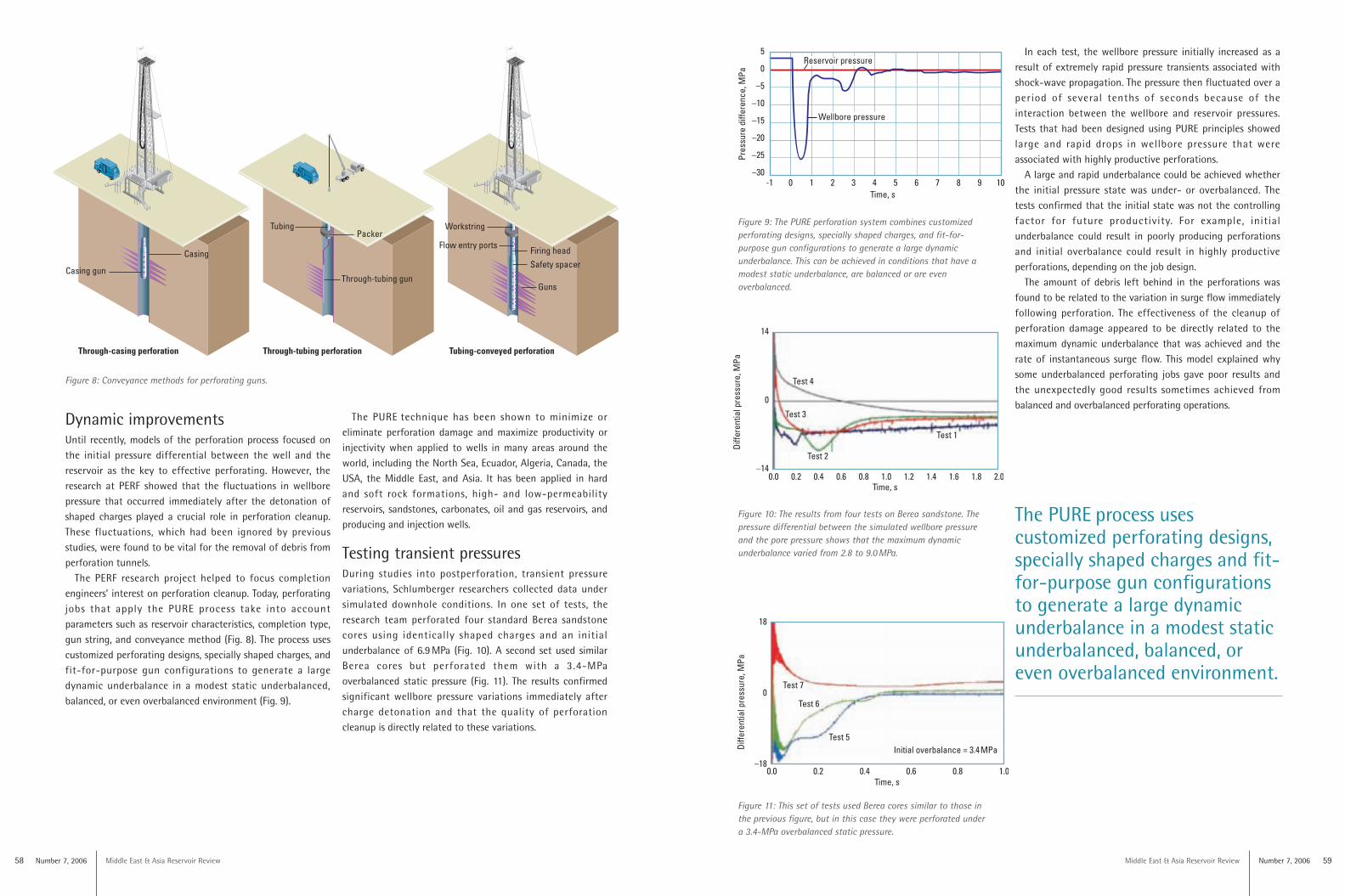
In each test, the wellbore pressure initially increased as aresult of extremely rapid pressure transients associated withshock-wave propagation. The pressure then fluctuated over aperiod of several tenths of seconds because of theinteraction between the wellbore and reservoir pressures.Tests that had been designed using PURE principles showedlarge and rapid drops in wellbore pressure that wereassociated with highly productive perforations.
A large and rapid underbalance could be achieved whetherthe initial pressure state was under- or overbalanced. Thetests confirmed that the initial state was not the controllingfactor for future productivity. For example, initialunderbalance could result in poorly producing perforationsand initial overbalance could result in highly productiveperforations, depending on the job design.
The amount of debris left behind in the perforations wasfound to be related to the variation in surge flow immediatelyfollowing perforation. The effectiveness of the cleanup ofperforation damage appeared to be directly related to themaximum dynamic underbalance that was achieved and therate of instantaneous surge flow. This model explained whysome underbalanced perforating jobs gave poor results andthe unexpectedly good results sometimes achieved frombalanced and overbalanced perforating operations.
5
0
–5
–10
–15
–20
–25
–30
Pres
sure
diffe
renc
e,M
Pa
-1 0 1 2 3 4Time, s
5 6 7 8 9 10
Reservoir pressure
Wellbore pressure
58 Number 7, 2006 Middle East & Asia Reservoir Review
Dynamic improvementsUntil recently, models of the perforation process focused onthe initial pressure differential between the well and thereservoir as the key to effective perforating. However, theresearch at PERF showed that the fluctuations in wellborepressure that occurred immediately after the detonation ofshaped charges played a crucial role in perforation cleanup.These fluctuations, which had been ignored by previousstudies, were found to be vital for the removal of debris fromperforation tunnels.
The PERF research project helped to focus completionengineers’ interest on perforation cleanup. Today, perforatingjobs that apply the PURE process take into accountparameters such as reservoir characteristics, completion type,gun string, and conveyance method (Fig. 8). The process usescustomized perforating designs, specially shaped charges, andfit-for-purpose gun configurations to generate a largedynamic underbalance in a modest static underbalanced,balanced, or even overbalanced environment (Fig. 9).
Figure 8: Conveyance methods for perforating guns.
The PURE technique has been shown to minimize oreliminate perforation damage and maximize productivity orinjectivity when applied to wells in many areas around theworld, including the North Sea, Ecuador, Algeria, Canada, theUSA, the Middle East, and Asia. It has been applied in hardand soft rock formations, high- and low-permeabilityreservoirs, sandstones, carbonates, oil and gas reservoirs, andproducing and injection wells.
Testing transient pressures During studies into postperforation, transient pressurevariations, Schlumberger researchers collected data undersimulated downhole conditions. In one set of tests, theresearch team perforated four standard Berea sandstonecores using identically shaped charges and an initialunderbalance of 6.9 MPa (Fig. 10). A second set used similarBerea cores but perforated them with a 3.4-MPaoverbalanced static pressure (Fig. 11). The results confirmedsignificant wellbore pressure variations immediately aftercharge detonation and that the quality of perforationcleanup is directly related to these variations.
The PURE process usescustomized perforating designs,specially shaped charges and fit-for-purpose gun configurationsto generate a large dynamicunderbalance in a modest staticunderbalanced, balanced, oreven overbalanced environment.
14
0
–14
Diffe
rent
ialp
ress
ure,
MPa
0.0 0.2 0.4 0.6 0.8 1.0 1.2 1.4 1.6 1.8 2.0Time, s
Test 1
Test 2
Test 3
Test 4
Figure 11: This set of tests used Berea cores similar to those in the previous figure, but in this case they were perforated under a 3.4-MPa overbalanced static pressure.
18
0
–18
Diffe
rent
ialp
ress
ure,
MPa
0.0 0.2 0.4 0.6 0.8 1.0Time, s
Initial overbalance = 3.4MPaTest 5
Test 6
Test 7
Figure 9: The PURE perforation system combines customizedperforating designs, specially shaped charges, and fit-for-purpose gun configurations to generate a large dynamicunderbalance. This can be achieved in conditions that have amodest static underbalance, are balanced or are evenoverbalanced.
Figure 10: The results from four tests on Berea sandstone. Thepressure differential between the simulated wellbore pressureand the pore pressure shows that the maximum dynamicunderbalance varied from 2.8 to 9.0 MPa.
Middle East & Asia Reservoir Review Number 7, 2006 6160 Middle East & Asia Reservoir ReviewNumber 7, 2006
The benefits of dynamic underbalanceA dynamic underbalance eliminates the need for large staticunderbalance pressure differentials and makes the preparationwork before perforation more straightforward. In addition,controlling the surge flow helps to limit the produced fluidvolumes during perforation cleanup. This, in turn, reduces therisk of sand influx and the possibility of gun sticking. Themethod also saves the time and the costs associated withpostperforation acid washes to remediate perforation damage.
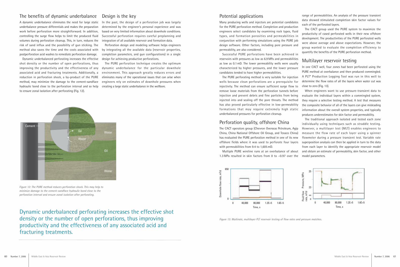
Dynamic underbalanced perforating increases the effectiveshot density or the number of open perforations, thusimproving the productivity and the effectiveness of anyassociated acid and fracturing treatments. Additionally, areduction in perforation shock, a by-product of the PUREmethod, may minimize the damage to the cement-sandfacehydraulic bond close to the perforation interval and so helpto ensure zonal isolation after perforating (Fig. 12).
Dynamic underbalanced perforating increases the effective shotdensity or the number of open perforations, thus improvingproductivity and the effectiveness of any associated acid andfracturing treatments.
fig11_perforating_m7
Oil
WaterOil
Water
Water
Cement
Cement
Figure 12: The PURE method reduces perforation shock. This may help tominimize damage to the cement-sandface hydraulic bond close to theperforation interval and ensure zonal isolation after perforating.
Design is the keyIn the past, the design of a perforation job was largelydetermined by the engineer’s personal experience and wasbased on very limited information about downhole conditions.Successful perforation requires careful preplanning andintegration of all available reservoir and formation data.
Perforation design and modeling software helps engineersby integrating all the available data (reservoir properties,completion parameters, and gun configurations) in a singledesign for achieving productive perforations.
The PURE perforation technique creates the optimumdynamic underbalance for the particular downholeenvironment. This approach greatly reduces errors andeliminates many of the operational issues that can arise whenengineers rely on estimates of downhole pressures whencreating a large static underbalance in the wellbore.
Potential applicationsMany producing wells and injectors are potential candidatesfor the PURE perforation method. Completion and productionengineers select candidates by examining rock types, fluidtypes, and formation porosities and permeabilities inconjunction with performing simulations using the PURE jobdesign software. Other factors, including pore pressure andpermeability, are also considered.
Successful PURE perforations have been achieved inreservoirs with pressures as low as 6.9 MPa and permeabilitiesas low as 0.1 mD. The lower permeability wells were usuallycharacterized by higher pressures, and the lower pressurecandidates tended to have higher permeabilities.
The PURE perforating method is very suitable for injectionwells because clean perforations are a prerequisite forinjectivity. The method can ensure sufficient surge flow toremove loose materials from the perforation tunnels beforeinjection and prevent debris and fine particles from beinginjected into and sealing off the pore throats. The methodhas also proved particularly effective in low-permeabilityformations that may require extremely high staticunderbalanced pressures for perforation cleanup.
Perforation quality, offshore ChinaThe CACT operators group (Chevron Overseas Petroleum, AgipChina, China National Offshore Oil Group, and Texaco China)has evaluated the PURE perforation method in one of its newoffshore fields where it was used to perforate four layerswith permeabilities from 9.4 to 1,605 mD.
Multiple PURE wireline runs at an overbalance of about1.3 MPa resulted in skin factors from 0 to –0.97 over the
range of permeabilities. An analysis of the pressure transientdata showed stimulated completion skin factor values foreach of the perforated layers.
The CACT group used the PURE system to maximize theproductivity of cased perforated wells in their new offshoredevelopment. The productivities of the PURE perforated wellswere above average and above expectations. However, thegroup wanted to evaluate the completion efficiency toquantify the benefits of the PURE perforation method.
Multilayer reservoir testingIn one CACT well, four zones had been perforated using the
PURE method at overbalance and then produced commingled.
A PLT* Production Logging Tool was run in this well to
determine the flow rates of all the layers when water cut was
close to zero (Fig. 13).
When engineers want to use pressure-transient data to
evaluate the individual layers within a commingled system,
they require a selective testing method. A test that measures
the composite behavior of all of the layers can give misleading
information about the overall system properties, and typically
produces underestimates for skin factor and permeability.The traditional approach isolated and tested each zone
individually using techniques such as straddle testing.However, a multilayer test (MLT) enables engineers tomeasure the flow rate of each layer using a spinnerflowmeter during a pressure transient test. Variable ratesuperposition analysis can then be applied in turn to the datafrom each layer to identify the appropriate reservoir modeland obtain an estimate of permeability, skin factor, and othermodel parameters.
Figure 13: Multirate, multilayer PLT reservoir testing of flow rates and pressure matches.
0 40,000
650
80,000
Time, s
1.2E+5 1.6E+5
0
0 40,000
25
80,000
Time, s
Pres
sure
,MPa
1.2E+5 1.6E+5
23
0
400
0 40,000
650
80,000
Time, s
1.2E+5 1.6E+5
0
0 40,000
25
80,000
Time, s
Pres
sure
,MPa
1.2E+5 1.6E+5
23
0
400
Number 7, 2006 63Middle East & Asia Reservoir Review62 Number 7, 2006 Middle East & Asia Reservoir Review
The MLT method derived from PLT testing involvessequential measurement of flow rates and pressure transientsfrom an individual layer or group of layers after a ratechange, preferably starting with the bottom layer andworking up. This process is referred to as a transientmultilayer test or simply an MLT.
Such MLTs can be performed on a producing well withoutpulling the completion and are therefore more cost effectivethan straddle tests. In addition, the total production from all thelayers is measured, whereas a series of straddle tests may betesting the same zone if the layers are not hydraulically isolated.
MLT data are crucial for reservoir management incommingled systems where more than one layer is producingand crossflow may be occurring between them. A goodunderstanding of the reservoir is crucial, particularly forreservoir simulation, voidage control, pressure maintenance,and workover decisions.
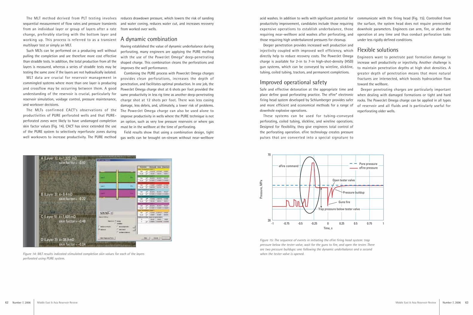
The MLTs confirmed CACT’s observations of theproductivities of PURE perforated wells and that PURE-perforated zones were likely to have undamaged completionskin factor values (Fig. 14). CACT has since extended the useof the PURE system to selectively reperforate zones duringwell workovers to increase productivity. The PURE method
reduces drawdown pressure, which lowers the risk of sandingand water coning, reduces water cut, and increases recoveryfrom worked over wells.
A dynamic combinationHaving established the value of dynamic underbalance duringperforating, many engineers are applying the PURE methodwith the use of the PowerJet Omega* deep-penetratingshaped charge. This combination cleans the perforations andimproves the well performance.
Combining the PURE process with PowerJet Omega chargesprovides clean perforations, increases the depth ofpenetration, and facilitates optimal production. In one job, thePowerJet Omega charge shot at 6 shots per foot provided thesame productivity in less rig time as another deep-penetratingcharge shot at 12 shots per foot. There was less casingdamage, less debris, and, ultimately, a lower risk of problems.The PowerJet Omega charge can also be used alone toimprove productivity in wells where the PURE technique is notan option, such as very low pressure reservoirs or where gasmust be in the wellbore at the time of perforating.
Field results show that using a combination design, tightgas wells can be brought on-stream without near-wellbore
Figure 14: MLT results indicated stimulated completion skin values for each of the layersperforated using PURE system.
A (Layer 1): k=1,322 mDskin factor=–0.97
B (Layer 3): k=9.4mD skin factor=–0.22
C (Layer 5): k=1,605mD skin factor=–0.48
D (Layer 7): k=38.9mDskin factor=–0.04
acid washes. In addition to wells with significant potential forproductivity improvement, candidates include those requiringexpensive operations to establish underbalance, thoserequiring near-wellbore acid washes after perforating, andthose requiring high underbalanced pressures for cleanup.
Deeper penetration provides increased well production andinjectivity coupled with improved well efficiency, whichdirectly help to reduce recovery costs. The PowerJet Omegacharge is available for 2-in to 7-in high-shot-density (HSD)gun systems, which can be conveyed by wireline, slickline,tubing, coiled tubing, tractors, and permanent completions.
Improved operational safetySafe and effective detonation at the appropriate time andplace define good perforating practice. The eFire* electronicfiring head system developed by Schlumberger provides saferand more efficient and economical methods for a range ofdownhole explosive operations.
These systems can be used for tubing-conveyedperforating, coiled tubing, slickline, and wireline operations.Designed for flexibility, they give engineers total control ofthe perforating operation. eFire technology creates pressurepulses that are converted into a special signature to
Figure 15: The sequence of events in initiating the eFire firing head system: trappressure below the tester valve, wait for the guns to fire, and open the tester. Thereare two pressure buildups: one following the dynamic underbalance and a secondwhen the tester valve is opened.
70
28
Pres
sure
,MPa
-1 -0.75 -0.5 -0.25
Pressure buildup
Pore pressureeFire pressure
0 0.25 0.5 0.75 1
Trap pressure below tester valve
eFire command
Open tester valve
Time, s
communicate with the firing head (Fig. 15). Controlled fromthe surface, the system head does not require prerecordeddownhole parameters. Engineers can arm, fire, or abort theoperation at any time and thus conduct perforation tasksunder less rigidly defined conditions.
Flexible solutionsEngineers want to penetrate past formation damage toincrease well productivity or injectivity. Another challenge isto maintain penetration depths at high shot densities. Agreater depth of penetration means that more naturalfractures are intersected, which boosts hydrocarbon flowtoward the wellbore.
Deeper penetrating charges are particularly importantwhen dealing with damaged formations or tight and hardrocks. The PowerJet Omega charge can be applied in all typesof reservoir and all fluids and is particularly useful forreperforating older wells.
(b) Initial gyroscope run
Relative bearing, 0º
Casing
Wireline swivel
Wireline perforatinginclinometer tool andcasing-collar locator
Gyroscope carrier
Upper weightedspring-positioning device
HSD gun,180º phasing
Upper indexing adapter
Lower weightedspring-positioning device
Lower indexing adapter
ChargesHSD gun
(c) Perforating run
Relative bearing, 0º
Charges
fig10_perforating_m7
Charges
(a)
Middle East & Asia Reservoir Review Number 7, 2006 6564 Middle East & Asia Reservoir ReviewNumber 7, 2006
Oriented perforating—finding the right direction
Reservoir rocks are usuallyheterogeneous—their properties varywith direction. In reservoir units thatdisplay large stress contrasts, properlyaligned perforations help to maximizethe stability of the perforation tunnels.In weakly consolidated reservoirs,selecting the best orientation helps tominimize the risk of sand production.Effective techniques for orientingperforations also help to reduce flowrestrictions and friction pressures during
fracturing. The resulting wider fracturespermit the use of larger sizes and higherconcentrations of proppant along withlower-viscosity, less-damaging fluids toimprove fracture conductivity.
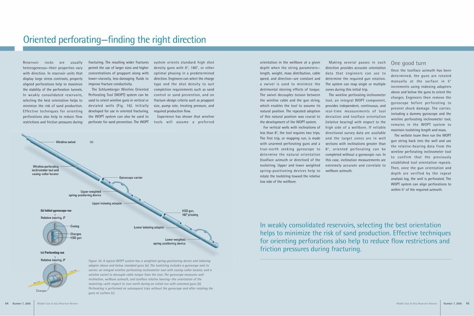
The Schlumberger Wireline OrientedPerforating Tool (WOPT) system can beused to orient wireline guns in vertical ordeviated wells (Fig. 16). Initiallydeveloped for use in oriented fracturing,the WOPT system can also be used toperforate for sand prevention. The WOPT
system orients standard high shotdensity guns with 0°, 180°, or otheroptimal phasing in a predetermineddirection. Engineers can select the chargetype and the shot density to suitcompletion requirements such as sandcontrol or sand prevention, and onfracture-design criteria such as proppantsize, pump rate, treating pressure, andrequired production flow.
Experience has shown that wirelinetools will assume a preferred
orientation in the wellbore at a givendepth when the string parameters—length, weight, mass distribution, cablespeed, and direction—are constant anda swivel is used to minimize thedetrimental steering effects of torque.The swivel decouples torsion betweenthe wireline cable and the gun string,which enables the tool to assume itsnatural position. The repeated adoptionof this natural position was crucial tothe development of the WOPT system.
For vertical wells with inclinations ofless than 8°, the tool requires two trips.The first trip, or mapping run, is madewith unarmed perforating guns and atrue-north seeking gyroscope todetermine the natural orientation(toolface azimuth or direction) of thetoolstring. Upper and lower weightedspring-positioning devices help torotate the toolstring toward the relativelow side of the wellbore.
Making several passes in eachdirection provides accurate orientationdata that engineers can use todetermine the required gun rotation.The system can map single or multiplezones during this initial trip.
The wireline perforating inclinometertool, an integral WOPT component,provides independent, continuous, andreal-time measurements of tooldeviation and toolface orientation(relative bearing) with respect to thehigh side of a wellbore. If reliabledirectional survey data are availableand the target zones are in wellsections with inclinations greater than8°, oriented perforating can becompleted without a gyroscopic run. Inthis case, inclination measurements areextremely accurate and correlate towellbore azimuth.
In weakly consolidated reservoirs, selecting the best orientationhelps to minimize the risk of sand production. Effective techniquesfor orienting perforations also help to reduce flow restrictions andfriction pressures during fracturing.
Figure 16: A typical WOPT system has a weighted spring-positioning device and indexingadapter above and below standard guns (a). The toolstring includes a gyroscope and itscarrier, an integral wireline perforating inclinometer tool with casing-collar locator, and awireline swivel to decouple cable torque from the tool. The gyroscope measures wellinclination, wellbore azimuth, and toolface relative bearing—the orientation of thetoolstring—with respect to true north during an initial run with unarmed guns (b).Perforating is performed on subsequent trips without the gyroscope and after rotating theguns at surface (c).
One good turnOnce the toolface azimuth has beendetermined, the guns are rotatedmanually at the surface in 5°increments using indexing adaptersabove and below the guns to orient thecharges. Engineers then remove thegyroscope before perforating toprevent shock damage. The carrier,including a dummy gyroscope and thewireline perforating inclinometer tool,remains in the WOPT system tomaintain toolstring length and mass.
The wellsite team then run the WOPTgun string back into the well and usethe relative-bearing data from thewireline perforating inclinometer toolto confirm that the previouslyestablished tool orientation repeats.Then, once the gun orientation anddepth are verified by the repeatanalysis log, the well is perforated. TheWOPT system can align perforations towithin 5° of the required azimuth.
66 Middle East & Asia Reservoir ReviewNumber 7, 2006
Every millisecond counts
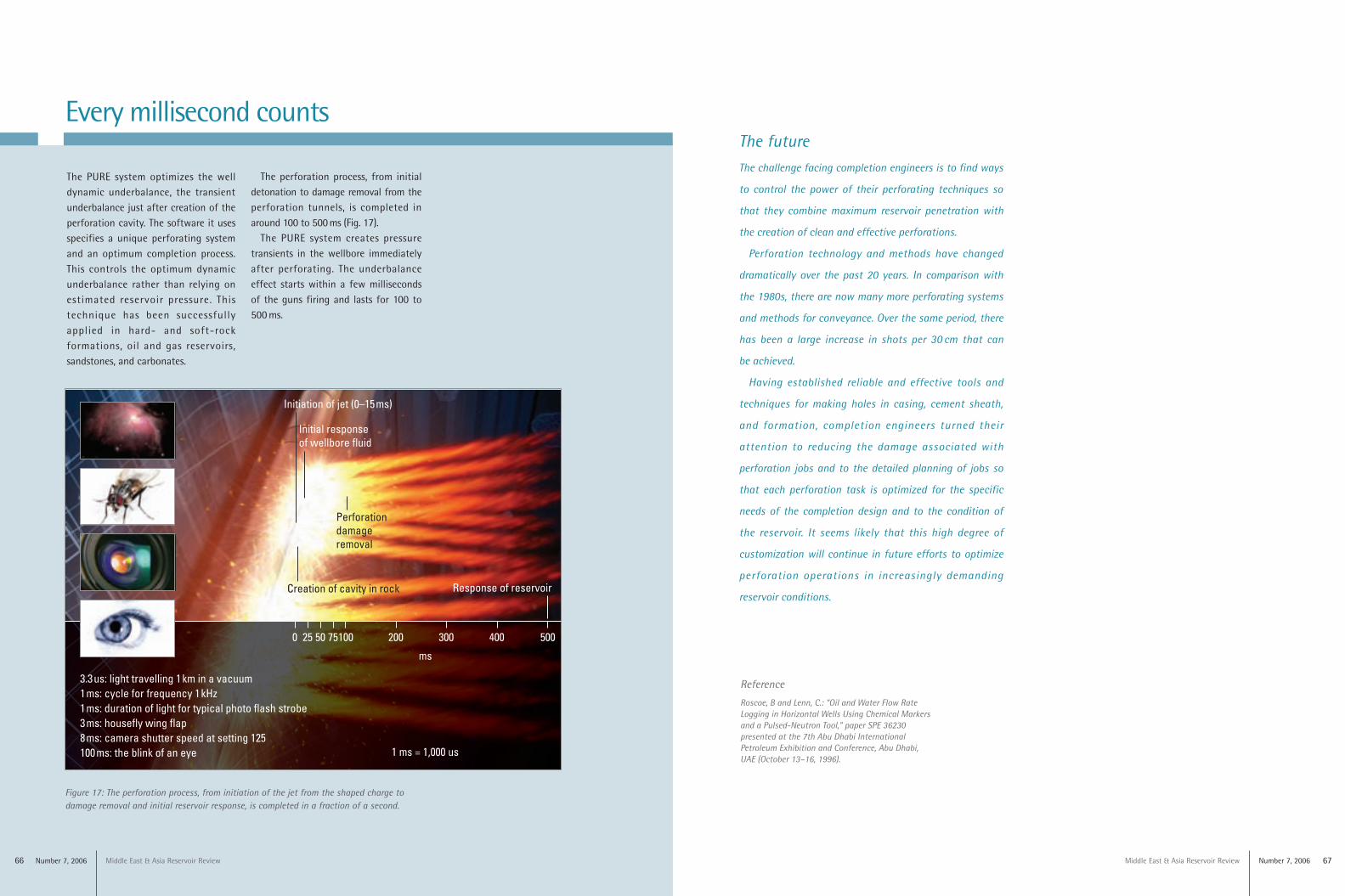
The PURE system optimizes the welldynamic underbalance, the transientunderbalance just after creation of theperforation cavity. The software it usesspecifies a unique perforating systemand an optimum completion process.This controls the optimum dynamicunderbalance rather than relying onestimated reservoir pressure. Thistechnique has been successfullyapplied in hard- and soft-rockformations, oil and gas reservoirs,sandstones, and carbonates.
Figure 17: The perforation process, from initiation of the jet from the shaped charge todamage removal and initial reservoir response, is completed in a fraction of a second.
fig19_perforating_m7
Middle East & Asia Reservoir Review Number 7, 2006 67
The futureThe challenge facing completion engineers is to find ways
to control the power of their perforating techniques so
that they combine maximum reservoir penetration with
the creation of clean and effective perforations.
Perforation technology and methods have changed
dramatically over the past 20 years. In comparison with
the 1980s, there are now many more perforating systems
and methods for conveyance. Over the same period, there
has been a large increase in shots per 30 cm that can
be achieved.
Having established reliable and effective tools and
techniques for making holes in casing, cement sheath,
and formation, completion engineers turned their
attention to reducing the damage associated with
perforation jobs and to the detailed planning of jobs so
that each perforation task is optimized for the specific
needs of the completion design and to the condition of
the reservoir. It seems likely that this high degree of
customization will continue in future efforts to optimize
perforation operations in increasingly demanding
reservoir conditions.
Reference
Roscoe, B and Lenn, C.: “Oil and Water Flow RateLogging in Horizontal Wells Using Chemical Markersand a Pulsed-Neutron Tool,” paper SPE 36230presented at the 7th Abu Dhabi InternationalPetroleum Exhibition and Conference, Abu Dhabi,UAE (October 13–16, 1996).
The perforation process, from initialdetonation to damage removal from theperforation tunnels, is completed inaround 100 to 500 ms (Fig. 17).
The PURE system creates pressuretransients in the wellbore immediatelyafter perforating. The underbalanceeffect starts within a few millisecondsof the guns firing and lasts for 100 to500 ms.