the second japanese modelica conferences is sponsored by ... · the second japanese modelica...
TRANSCRIPT

The Second Japanese Modelica Conferences is sponsored by:
The Second Japanese Modelica Conference is organized by ANSYS and Modelica Association

2 Program of the 2nd Japanese Modelica Conference | May 17-18, 2018 | Tokyo, Japan
Program of the 2nd Japanese Modelica Conference
Tokyo, Japan, May 17-18, 2018
Editors:
Mr. Sameer Kher and Dr. Yutaka Hirano
Organized by:
ANSYS Inc.
Southpointe
2600 ANSYS Drive
Canonsburg, PA 15317
USA
in co-operation with:
Modelica Association
c/o PELAB, Linköpings Univ.
SE-581 83 Linköping
Sweden
Conference location:
Bellesalle Jimbocho
Sumitomo Fudosan Chiyoda First Building South
3-2-1 Nishi-Kanda, Chiyoda-ku, Tokyo
Japan
Copyright © Modelica Association, 2018

Program of the 2nd Japanese Modelica Conference | May 17-18, 2018 | Tokyo, Japan 3
Welcome Message
Following the first successful conference in 2016, the 2nd Japanese Modelica Conference takes place in
Tokyo again. With this effort, we hope to create an arena in Japan and Asia for sharing knowledge and
learning about the latest scientific and industrial progress related to Modelica and FMI (Functional
Mockup Interface). We are now proud to present a conference with:
• 3 Keynote speeches
• 37 paper presentations
• An exhibition area featuring 9 exhibitors
• Great venue location in the heart of Tokyo
According to Modelica Association standards, all papers are peer-reviewed and will be freely available
for download.
We want to acknowledge the support we received from the conference board and program committee.
Special thanks to our colleagues at ANSYS Inc. and ANSYS Japan K.K. for taking care of all the
practical matters. Support from the conference sponsors is gratefully acknowledged. Last but not least,
thanks to all authors, keynote speakers, and presenters for their contributions to this conference.
We wish all participants an enjoyable and inspiring conference!
Tokyo May 17,
Sameer Kher & Yutaka Hirano
Sameer Kher

4 Program of the 2nd Japanese Modelica Conference | May 17-18, 2018 | Tokyo, Japan

Program of the 2nd Japanese Modelica Conference | May 17-18, 2018 | Tokyo, Japan 5
Keynotes Speakers
Hilding Elmqvist
Mogram AB, Modelon AB
Modelica - History, State, Needs, Trends and
Possibilities
Model based product design requires both
intuitive and effective user interface and
powerful computing power. The presentation
will contain a brief history of Modelica
evolution and current status including some
applications. Some new needs that are
currently not covered will be discussed. New
technical possibilities will be introduced, such
as web apps for intuitive and effective user
interaction and easy access, domain specific
language extensions for advanced modeling
capabilities and cloud computing for large
scale simulation deployment..
Koichi Ohtomi
Meiji University
Using Modelica Effectively in Industrial
Research and Development
The main task of product development is to
develop a good product at lower cost and to
bring it to market in a shorter period.
Conventional computer-aided design and
computer-aided engineering systems are well
established in this regard. However, although
upstream design is particularly important in
product development to add value and
incorporate the required functions, it is
difficult to apply conventional systems to the
upstream design stage due to the lack of design
information at that stage. As a solution to this
issue, we are developing the product
development environment by applying
"Delight Design by System Simulation"
methodology, which can be applied to the early
design stage of product development including
the conceptual and functional design phases.
Here Delight Design is equivalent to attractive
quality. I introduce the Delight Design
technique and the application of "Crane cabin
design" and "Hair dryer design". Delight
Design is realized by applying "Modelica-
based System Simulation" including not only
product model but cognitive and human
models.
6 Program of the 2nd Japanese Modelica Conference | May 17-18, 2018 | Tokyo, Japan
Torsten Blochwitz Andreas Junghanns
ESI ITI QTronic
10 Years of FMI: Where Are We Now, Where
Do We Go?
The exchange of simulation models is a key
enabler for the distributed model based
development and verification process. This
was the main motivation to start the
MODELISAR project 10 years ago. The main
result of this research project funded by the
European Union was the tool independent
Functional Mock up Interface (FMI) for Model
Exchange and Co-Simulation, which is now
maintained within a Modelica Association
Project. By now more than 100 tools support
FMI. The presentation provides an update on
the current status, planned new features and the
roadmap towards a new release. A few
examples demonstrate typical FMI use cases.
As an outlook some related ongoing research
projects like ACOSAR and EMPHYSIS are
presented.

Program of the 2nd Japanese Modelica Conference | May 17-18, 2018 | Tokyo, Japan 7
Program Committee
General Chair
Mr. Sameer Kher, ANSYS Inc., USA
Program Chair
Dr. Yutaka Hirano, Toyota Motor Corporation, Japan
Program Board
Dr. Yutaka Hirano, Toyota Motor Corporation, Japan
Prof. Peter Fritzson, Linköping University, Sweden
Prof. Martin Otter, DLR, Germany
Dr. Hilding Elmqvist, Mogram, Sweden
Dr. Michael Tiller, Xogeny Inc., USA
Program Committee
Prof. Bernhard Bachmann, Fachhochschule Bielefeld, Bielefeld, Germany
Prof. John Baras, University of Maryland, Maryland, USA
Dr. John Batteh, Modelon, Inc., Ann Arbor, USA
Christian Bertsch, Robert Bosch GmbH, Stuttgart, Germany
Volker Beuter, VI-grade GmbH, Marburg, Germany
Torsten Blochwitz, ESI ITI GmbH, Dresden, Germany
Dr. Marco Bonvini, Whisker Labs, Oakland, USA
Dr. Scott Bortoff, Mitsubishi Electric Research Laboratories, Cambridge, USA
Timothy Bourke, INRIA, Paris, France
Daniel Bouskela, Électricité de France, Paris, France
Dr. Daniel Burns, Mitsubishi Electric Research Laboratories, Cambridge, USA
Prof. Francesco Casella, Politecnico di Milano, Milano, Italy
Prof. Hyung Yun Choi, HongIk Univesity, Seoul, Korea
Dr. Johan de Kleer, Xerox PARC, Palo Alto, USA
Mike Dempsey, Claytex, Leamington Spa, United Kingdom
Dr. Hilding Elmqvist, Mogram AB, Lund, Sweden
Dr. Jens Frenkel, ESI ITI GmbH, Dresden, Germany
Prof. Takashi Fukue, Iwate University, Iwate, Japan
Leo Gall, LTX Simulation Gmbh, Munich, Germany
Dr. Rui Gao, Modelon KK, Tokyo, Japan
Khalil Ghorbal, INRIA, Le Chesnay, France
Peter Harman, CAE Tech Limited, Leamington Spa, United Kingdom
Prof. Anton Haumer, OTH Regensburg, Regensburg, Germany
Dr. Dan Henriksson, Dassault Systemes, Lund, Sweden
Dr. Yutaka Hirano, Toyota Motor Corporation, Tokyo, Japan
Prof. Bengt Jacobson, Chalmers University of Technology, Gothenburg, Sweden
Prof. Tommi Karhela, VTT Technical Research Centre , Espoo, Finland
Åke Kinnander, Siemens Industrial Turbomachinery AB, Finspang, Sweden
Dr. Jiri Kofranek, Charles University Prague, Prague, Czech Republic
Satoshi Komori, MAZDA Motor, Hiroshima, Japan
Dr. Christopher Laughman, Mitsubishi Electric Research Laboratories, Cambridge, USA
Dr. Alexandra Mehlhase, Arizona State Univeristy, Tempe, USA
Dr. Lars Mikelsons, Robert Bosch GmbH, Lohr am Main, Germany
Dr. Ramine Nikoukhah, Altair Engineering, Paris, France

8 Program of the 2nd Japanese Modelica Conference | May 17-18, 2018 | Tokyo, Japan
Prof. Henrik Nilsson, University of Nottingham, Nottingham, United Kingdom
Prof. Hidekazu Nishimura, Keio Gijuku University, Yokohama, Japan
Prof. Kenichiro Nonaka, Tokyo City University, Tokyo, Japan
Thierry-Stephane Nouidui, LBL, Berkeley , USA
Prof. Shigeru Oho, Nippon Institute of Technology, Tokyo, Japan
Prof. Koichi Ohtomi, University of Tokyo, Tokyo, Japan
Prof. Martin Otter, DLR, Oberpfaffenhofen, Germany
Dr. Andreas Pillekeit, dSPACE, Dortmund, Germany
Dr. Adrian Pop, Linköping University, Linköping, Sweden
Johan Rhodin, 84 Codes Consulting LLC, Missouri, USA
Dr. Clemens Schlegel, Schlegel Simulation GmbH, Munich, Germany
Dr. Peter Schneider, Fraunhofer IIS, Dresden, Germany
Prof. Stefan-Alexander Schneider, Hochschule Kempten, Kempten, Germany
Michael Sielemann, Modelon AB, Lund, Sweden
Dr. Martin Sjölund, Linköping University, Linköping, Sweden
Prof. Thierry Soriano, Université de Toulon , Toulon, France
Dr. Rita Streblow, RWTH Aachen University, Aachen, Germany
Dr. Ed Tate, Exa, Livonia, USA
Dr. Wilhelm Tegethoff, TLK-Thermo GmbH, Braunschweig, Germany
Matthis Thorade, Universität der Künste Berlin, Berlin, Germany
Dr. Michael Tiller, Xogeny Inc., Michigan, USA
Dr. Jakub Tobolar, DLR, Oberpfaffenhofen, Germany
Dr. Hubertus Tummescheit, Modelon, Hartford, USA
Prof. Alfonso Urquia, UNED, Madrid, Spain
Prof. Luigi Vanfretti, Rensselaer Polytechnic Institute, Troy, USA
Dr. Stéphane Velut, Modelon AB, Lund, Sweden
Stefan Wischhusen, XRG Simulation Gmbh, Hamburg, Germany
Dr. Dirk Zimmer, DLR, Oberpfaffenhofen, Germany

Program of the 2nd Japanese Modelica Conference | May 17-18, 2018 | Tokyo, Japan 9
General Schedule
Thursday, May 17: Time Room A Room B Exhibition
Room
10:00-10:15 Opening
Exhibition
10:15-11:15 Keynote 1
(Dr. Hilding Elmqvist)
11:15-12:15 Keynote 2
(Dr. Koichi Otomi)
12:15-13:15 Lunch,
Exhibition
13:15-14:30 Session 1a:
Automotive Applications 1
Session 1b:
Thermal System Applications 1 Exhibition
14:30-14:55 Break,
Exhibition
14:55-16:10 Session 2a:
Automotive Applications 2
Session 2b:
Thermal System Applications 2 Exhibition
16:10-16:35 Break,
Exhibition
16:35-17:50 Session 3a:
Automotive Applications 3
Session 3b:
Thermal System Applications 3 Exhibition
17:50-18:00 Break
18:00-20:00 Dinner
Friday, May 18: Time Room A Room B Exhibition
Room
10:00-10:05 Opening
Exhibition
10:05-11:05 Keynote 3
(Mr. Torsten Blochwitz,
Mr. Andreas Junghanns)
11:10-12:00 Session 4a:
HILS,
Real Time Simulation
Session 4b:
Electronic Systems Application
12:00-13:35 Lunch,
Exhibition
13:35-14:50 Session 5a:
Model Based Development
Session 5b:
Mechanical Systems Application 1 Exhibition
14:50-15:15 Break,
Exhibition
15:15-16:30 Session 6a:
FMI,
Simulation Technologies 1
Session 6b:
Mechanical Systems Application 2,
Control
Exhibition
16:30-16:55 Break,
Exhibition
16:55-17:45 Session 7a:
FMI,
Simulation Technologies 2
Session 7b:
Vendor Session Exhibition
17:45-17:50 Break,
Exhibition
17:50-18:00 Closing

10 Program of the 2nd Japanese Modelica Conference | May 17-18, 2018 | Tokyo, Japan
Venue Map
Bellesalle Jimbocho
Sumitomo Fudosan Chiyoda First Building South
3-2-1 Nishi-Kanda, Chiyoda-ku, Tokyo

Program of the 2nd Japanese Modelica Conference | May 17-18, 2018 | Tokyo, Japan 11
Scientific Program
Thursday, May 17:
10:15-11:15 Keynote 1 “Modelica - History, State, Needs, Trends and Possibilities”
Hilding Elmqvist (Mogram AB, Modelon AB)
11:15-12:15 Keynote 2 “Delight Design by System Simulation”
Koichi Ohtomi (Meiji University)
13:15-14:30 Session 1a: Automotive Applications 1 Chair: Yutaka Hirano
“Riding Comfort Simulation with air ride seat for heavy duty vehicle”
Hyung Yun Choi, Whe-Ro Lee (HongIk University),
Jong-Chan Park and Kee-Young Yang (Hyundai)
“Assessment of Ride Quality at Lane Change Maneuver Using Virtual Human Driver Model”
Manyong Han, Hyung Yun Choi (HongIk University),
Akinari Hirao (Nissan),
and Stefan Kirschbichler (VIRTUAL VEHICLE)
“Combustion Engine Mechanism Analyses Using SimulationX”
Tomohide Hirono and Takanori Watanabe (NewtonWorks)
13:15-14:30 Session 1b: Thermal System Applications 1 Chair: Christopher Laughman
“The CryoLib - Modelling Superconductors with Modelica”
Alexander Pollok and Dirk Zimmer (DLR)
“Robust Modeling of Directed Thermofluid Flows in Complex Networks “
Dirk Zimmer, Daniel Bender and Alexander Pollok (DLR)
“Liquid Cooling Applications in Twin Builder”
Anand Pitchaikani, Katrin Prölss, Mathias Strandberg, Hubertus Tummescheit (Modelon
AB)
and Sameer Kher (ANSYS Inc.)
14:55-16:10 Session 2a: Automotive Applications 2 Chair: Hyung Yun Choi
“Development of a Flex-PLI System Model and Investigations of Injury”
Yong-Ha Han, In-Hyeok Lee (Hyundai)
and Whe-Ro Lee (ESI Korea)
“Vehicle Systems Modelling and Analysis (VeSyMA) Platform “
Hannah Hammond-Scott and Mike Dempsey (Claytex)

12 Program of the 2nd Japanese Modelica Conference | May 17-18, 2018 | Tokyo, Japan
“Dual-Clutch Transmission Model Reduction Function”
Romain Gillot, Alessandro Picarelli and Mike Dempsey (Claytex)
14:55-16:10 Session 2b: Thermal System Applications 2 Chair: Alexander Pollok
“FluidDynamics Library for Coarse-Grid CFD-Simulation in Modelica”
Stefan Wischhusen, Timo Tumforde and Hans-Hermann Wurr (XRG Simulation)
“Modeling and Coordinated Control of an Air-Source Heat Pump and Hydronic Radiant
Heating System “
Christopher Laughman, Scott Bortoff and Hongtao Qiao (MERL)
“Semiconductor Package Thermal Impedance Extraction for Modelica Thermal Network
Simulation Combined with VHDL-AMS model”
R Eiji Nakamoto, Kentaro Maeda and Takayuki Sekisue (ANSYS Japan)
16:35-17:50 Session 3a: Automotive Applications 3 Chair: Leo Gall
“Modeling of Fuel Cell Hybrid Vehicle in Modelica: Architecture and Drive Cycle Simulation”
Sara Sigfridsson, Lixiang Li, Håkan Runvik, Jesse Gohl, Antonin Joly and Kristian Soltesz
(Claytex)
“Modelling & Analysis of a Fuel Cell Hybrid Electric Vehicle using Real-World & Standard
Driving Conditions “
Raees Basheer Kunthirikkal Parambu, Mike Dempsey and Alessandro Picarelli (Claytex)
“Hyundai framework for vehicle dynamics engineering based on Modelica and FMI”
Kwang Chan Ko (Hyundai),
Erik Durling (Modelon AB),
Jong Chan Park (Hyundai),
Wonyul Kang (Institute of Vehicle Engineering)
and Johan Andreasson (Modelon AB)
16:35-17:50 Session 3b: Thermal System Applications 3 Chair: Shigeru Oho
“Modelling of Oil Film Bearings”
Tatsuro Ishibashi (Meidensha)
and Tadao Kawai (Osaka City University)
“Gas Compressor System Simulation using Functional Mockup Interface for Human
Machine Interface and Control“
Ryan Magargle and Hemanth Kolera-Gokula (ANSYS Inc.)
“A New Library For Modeling and Simulation of Pneumatic Systems”
Maximilian Kormann, Clement Coic and Guillaume Viry (Dassault Systèmes)

Program of the 2nd Japanese Modelica Conference | May 17-18, 2018 | Tokyo, Japan 13
Friday, May 18:
10:05-11:05 Keynote 3 “10 Years of FMI: Where Are We Now, Where Do We Go?"
Torsten Blochwitz (ESI ITI), Andreas Junghanns (QTronic)
11:10-12:00 Session 4a: HILS, Real Time Simulation Chair: Rui Gao
“The DLR EtherCAT Library - A template based code-generation scheme for accessing real-
time hardware from Modelica”
Tobias Bellmann and Fabian Buse (DLR)
“Modelling and Development of a Pseudo-Hydraulic Power Steering Model for use in Real-
Time Applications”
Theodor Ensbury, Mike Dempsey (Claytex)
and Peter Harman (CAE Tech)
11:10-11:35 Session 4b: Electronic Systems Application Chair: Tommi Karhela
“Modelling silicon carbide based power electronics in electric vehicles as a study of the
implementation of the semiconductor devices using Dymola”
Leonard Janczyk (Dassault Systèms),
Yoshihisa Nishigori (ROHM)
and Yasuo Kanehira (Dassault Systèms Japan)
13:35-14:50 Session 5a: Model Based Development Chair: Dirk Zimmer
“AUTOMATED TEST OF CVT CONTROL SOFTWARE, USING FMI AND MODELICA
MODELS”
Zeng, Weihua (Hunan Jianglu & Rongda Vehicle Transmission),
Liu Fei and Belmon, Lioneli (Global Crown Technology)
“The Fault library - A new Modelica library allows for the systematic simulation of non-
nominal system behavior “
Julia Gundermann, Artem Kolesnikov, Morgan Cameron and Torsten Blochwitz (ESI ITI)
“Application for Optimization of Control Parameters for Multi-body and Hydraulics System
by using FMU”
Nobumasa Ishida and Hideyuki Muramatsu (Dassault Systèms Japan)
13:35-14:50 Session 5b: Mechanical Systems Application 1
Chair: Ken-ichiro Nonaka
“Analysis of Lift-Generating Disk Type Blade Wind Power System Using Modelica”
Yeungmin Yoo, Soyoung Lee, Jaehyun Yoon and Jongsoo Lee (Yonsei Univeristy)

14 Program of the 2nd Japanese Modelica Conference | May 17-18, 2018 | Tokyo, Japan
“Modelling of Asymmetric Rotor and Cracked Shaft “
Tatsuro Ishibashi (Meidensha),
Atsushi Yoshida and Tadao Kawai (Osaka City University)
“Composable Modelling for a Hybrid Gearbox” Joshua Sutherland (The University of Tokyo)
and Rui Gao (Modelon K.K.)
15:15-16:30 Session 6a: FMI, Simulation Technologies 1 Chair: Torsten Blochwitz
“Toward the actual model exchange using FMI in practical use cases in Japanese automotive
industry”
Yutaka Hirano (Toyota),
Junichi Ichihara (AZAPA),
Haruki Saito (Nissan),
Yosuke Ogata (Siemens K.K.),
Takayuki Sekisue (ANSYS Japan)
and Satoshi Koike (Denso)
“Managing Heterogeneous Simulations Using Architecture-Driven Design”
Bruno Loyer, Nico Vansina and Yosuke Ogata (Siemens)
“Simulation of high-index DAEs and ODEs with constraints in FMI “
Masoud Najafi (Altair)
15:15-16:30 Session 6b: Mechanical Systems Application 2, Control Chair: Koichi Ohtomi
“Universal Controllers for Architecture Simulation”
Alexander Pollok (DLR) and Francesco Casella (Politecnico di Milano,)
“Mission-Dependent Sequential Simulation for Modeling and Trajectory Visualization of
Reusable Launch Vehicles“
Lale Evrim Briese (DLR)
“Model predictive allocation control for leg-wheel mobile robot on loose soil considering wheel
dynamics”
Takatsugu Oda, Hiroki Yoshikawa, Naoki Shibata, Kenichiro Nonaka and Kazuma
Sekiguchi (Tokyo City University)
16:55-17:45 Session 7a: FMI, Simulation Technologies 2 Chair: Yutaka Hirano
“Generating FMUs for the Feature-Based Language Bloqqi”
Niklas Fors (Lund University),
Joel Petersson and Maria Henningsson (Modelon AB)
“A Web Architecture for Modeling and Simulation“
Hilding Elmqvist, Martin Malmheden and Johan Andreasson (Modelon AB)

Program of the 2nd Japanese Modelica Conference | May 17-18, 2018 | Tokyo, Japan 15
16:55-17:45 Session 7b: Vendor Session Chair: Joshua Sutherland
“Multibody simulation and control of kinematic systems with FMI/FMU”
Francois Chapuis, Jean Daniel Beley, Stephane Garreau, Olivier Roll, Tim Puls, Leon Voss
and Sameer Kher (ANSYS Inc.)
“Deployment process for Modelica-based models “
Takashi Iwagaya (Cybernet Systems),
Chad Schmitke and Tetsu Yamaguchi (Maplesoft)

16 Program of the 2nd Japanese Modelica Conference | May 17-18, 2018 | Tokyo, Japan
One Page Abstracts
Contents
Session 1a: Automotive Applications 1
Riding Comfort Simulation with air ride seat for heavy duty vehicle 19
Assessment of Ride Quality at Lane Change Maneuver Using Virtual Human Driver
Model
20
Combustion Engine Mechanism Analyses Using SimulationX 21
Session 1b: Thermal System Applications 1
The CryoLib - Modelling Superconductors with Modelica 22
Robust Modeling of Directed Thermofluid Flows in Complex Networks 23
Liquid Cooling Applications in Twin Builder- Industrial Paper 24
Session 2a: Automotive Applications 2
Development of a Flex-PLI System Model and Investigations of Injury 25
Vehicle Systems Modelling and Analysis (VeSyMA) Platform 26
Dual-Clutch Transmission Model Reduction Function 27
Session 2b: Thermal System Applications 2
FluidDynamics Library for Coarse-Grid CFD-Simulation in Modelica 28
Modeling and Coordinated Control of an Air-Source Heat Pump and Hydronic
Radiant Heating System
29
Semiconductor Package Thermal Impedance Extraction for Modelica Thermal
Network Simulation Combined with VHDL-AMS model
30

Program of the 2nd Japanese Modelica Conference | May 17-18, 2018 | Tokyo, Japan 17
Session 3a: Automotive Applications 3
Modeling of Fuel Cell Hybrid Vehicle in Modelica: Architecture and Drive Cycle
Simulation
31
Modelling & Analysis of a Fuel Cell Hybrid Electric Vehicle using Real-World &
Standard Driving Conditions
32
Hyundai framework for vehicle dynamics engineering based on Modelica and FMI 33
Session 3b: Thermal System Applications 3
Modelling of Oil Film Bearings 34
Gas Compressor System Simulation using Functional Mockup Interface for Human
Machine Interface and Control
35
A New Library For Modeling and Simulation of Pneumatic Systems 36
Session 4a: HILS, Real Time Simulation
The DLR EtherCAT Library - A template based code-generation scheme for accessing
real-time hardware from Modelica
37
Modelling and Development of a Pseudo-Hydraulic Power Steering Model for use in
Real-Time Applications
38
Session 4b: Electronic Systems Application
Modelling silicon carbide based power electronics in electric vehicles as a study of the
implementation of the semiconductor devices using Dymola
39
Session 5a: Model Based Development
AUTOMATED TEST OF CVT CONTROL SOFTWARE, USING FMI AND
MODELICA MODELS
40
The Fault library - A new Modelica library allows for the systematic simulation of
non-nominal system behavior
41
Application for Optimization of Control Parameters for Multi-body and Hydraulics
System by using FMU
42

18 Program of the 2nd Japanese Modelica Conference | May 17-18, 2018 | Tokyo, Japan
Session 5b: Mechanical Systems Application 1
Analysis of Lift-Generating Disk Type Blade Wind Power System Using Modelica 43
Modelling of Asymmetric Rotor and Cracked Shaft 44
Composable Modelling for a Hybrid Gearbox 45
Session 6a: FMI, Simulation Technologies 1
Toward the actual model exchange using FMI in practical use cases in Japanese
automotive industry
46
Managing Heterogeneous Simulations Using Architecture-Driven Design 47
Simulation of high-index DAEs and ODEs with constraints in FMI 48
Session 6b: Mechanical Systems Application 2, Control
Universal Controllers for Architecture Simulation 49
Mission-Dependent Sequential Simulation for Modeling and Trajectory Visualization
of Reusable Launch Vehicles
50
Model predictive allocation control for leg-wheel mobile robot on loose soil
considering wheel dynamics
51
Session 7a: FMI, Simulation Technologies 2
Generating FMUs for the Feature-Based Language Bloqqi 52
A Web Architecture for Modeling and Simulation 53
Session 7b: Vendor Session
Multibody simulation and control of kinematic systems with FMI/FMU 54
Deployment process for Modelica-based models 55

Program of the 2nd Japanese Modelica Conference | May 17-18, 2018 | Tokyo, Japan 19
Riding Comfort Simulation with Air Ride Seat for Heavy
Duty Vehicle
Hyung Yun Choi1 Whe-Ro Lee1 Jong-Chan Park2 Kee-Young Yang2
1HongIk University, Korea, [email protected], [email protected]
2Hyundai Motor Company, Korea, {impactpart, yky}@hyundai.com
The design of driver's seat suspension of the commercial truck differs from the one of the passenger
car. The vibration and the structural characteristics of the suspension are consequently quite different.
Unlike passenger cars, the vibration frequency of commercial truck suspensions is considerably low at
1 to 3 Hz. (Mayton, 2006). The truck seat has an air ride seat. The structural design of air ride seat at
heavy-duty vehicle includes serial and parallel combinations of the shock absorber, air spring, and PU
foam pad to achieve a good vibration damping. The 1D lumped network solution is an effective design
tool with the multi-physical subcomponents. And this also enables a direct coupling into the system
modeling of the vehicle body for an optimal calibration of engineering parameters taking the relevant
dynamic performance of neighboring parts into account. The mechanical characteristics of each
component and their assembly were identified for the 1D modeling. The result of validation and
verification of the proposing 1D model of the air ride seat is also introduced.
Figure 1. 3D CAD (top) and Diagram (bottom) views of air ride seat frame
The air ride seat in a heavy-duty vehicle has multi-physical subcomponents such as air spring, shock
absorber, and viscoelastic PU foam pad. The 1D lumped network modeling can be effectively used at
the front-loading phase to optimize its engineering design parameters taking the relevant dynamic
performance of neighboring parts into account. The mechanical characteristics of each major
component in-vitro was experimentally identified and the corresponding 1D model was accordingly
validated. The assembly of multi-physical subcomponents into the air ride seat was also validated
against the harmonic excitation with a good correlation of the transfer function. In order to verify the
practical application of the 1D air ride seat model for a ride comfort assessment, the standard ISO
2631 process was carried out for evaluation of each driving over the highway and the rough road. The
effects of damping levels of shock absorber on the comfort score were also investigated.
References Mayton AG, DuCarme JP, Jobes CC, Matty TJ. ASME. Laboratory Investigation of Seat
Suspension Performance During Vibration Testing., 2006. doi:10.1115/IMECE2006-14146 Whe-Ro Lee, Manyong Han,
Hyung Yun Choi, Jungtae Yang, Inhyeok Lee, Kee Young Yang,
Jong-Chan Park. PAM User Conference Asia. Air Ride Seat for Heavy Duty Vehicle. 2017

20 Program of the 2nd Japanese Modelica Conference | May 17-18, 2018 | Tokyo, Japan
Assessment of Ride Quality at Lane Change Maneuver
using Virtual Human Driver Model
Manyong Han1 Hyung Yun Choi2 Akinari Hirao3 Stefan Kirschbichler4
1Dept. of Mechanical Eng., HongIk University, Korea, [email protected] 2Mechanical System Design Eng. Dept., HongIk University, Korea, [email protected]
3Nissan Motor Co., Ltd., Japan, [email protected] 4VIRTUAL VEHICLE, Austria, [email protected]
The occupant kinematics occurring at a lane change maneuver affects the local ride quality. The
precise analysis of the occupant kinematics requires a comprehensive understanding of the physiologic
response to human body as well as the vehicle kinematics. A series of vehicle-based tests also
confirmed that the alertness level of vehicle occupants is one of the important biomechanical elements.
Therefore, it is necessary to have a virtual human body model (HBM), an occupant surrogate at CAE
design process, with active muscle forces to represent the reflexive response of human beings. An
active human body model that produces joint torques with PID closed-loop control as mimicking a
bracing action to keep the sitting posture against the external jerk has been developed. In this study, this
active human body model is validated against the subject test by simulating the similar occupant
kinematics at a single lane change maneuvers. To further verify the use of active HBM as a design tool,
an artificial lane change maneuver with a reduced lateral jerk is fabricated and good matching
occupant kinematics are predicted.
Figure 1. Frontal view of occupant kinematics at lane change simulation
The active human body model primarily developed for a ride comfort simulation to investigate the
vibration response of human occupants is applied to predict relatively short-term ride quality via
simulating a kinematics at an evasive lane change. The lateral movements of head and torso at three
awareness conditions, unaware, anticipated, and informed were validated against the vehicle-based
subject test.
In order to verify a practical application of the active human body model in the design
process of the ride quality, an artificial single lane change maneuver with reduced lateral jerk was
fabricated and its effect on the occupant kinematics was investigated. The model predicted a joint
work, regarded as a muscle energy used to maintain the sitting posture against the lateral G-force with a
comparable reduction at the created lane change maneuver and successfully demonstrated its feasibility of
serving as an objective design tool for quantifying the ride quality.
References H.Y. Choi, M. Han, A. Hirao and H. Matsuoka, Virtual Occupant Model for Riding Comfort Simulation, 12th
International Modelica Conference, Czech Republic, 2017.
P. Huber, M. Christova, G. A. D’Addetta, E. Gallasch, S. Kirschbichler, C. Mayer, A. Prüggler, A. Rieser and W. Sinz,
D.Wallner, Muscle Activation Onset Latencies and Amplitudes during Lane Change in a Full Vehicle Test, IRCOBI
Conference 2013

Program of the 2nd Japanese Modelica Conference | May 17-18, 2018 | Tokyo, Japan 21
[Industrial paper] Combustion Engine Mechanism Analyses
Using SimulationX
Tomohide Hirono1 Takanori Watanabe2
1,2 CAE Research & Development Center, NewtonWorks Corp., Japan,
{hirono.tomohide,twatanabe}@newtonworks.co.jp
When we apply more efficient combustion profile using advanced mecha- nisms to ICEs, vehicles
with ICEs can exceed BEVs from the view of total environmental performance. This paper illustrates
SimulationX, a Modeli- ca simulation tool, can be a tool for the developments of advanced mechan-
ical systems such as new valve trains and cranking systems. This paper al- so shows a case of FMI co-
simulation of cam phaser between the tool and another hydraulic simulation tool which is used to
model a conventional hydraulic system of an existing ICE.
Figure 1 Hydraulic Cam Phaser (5 x 2 Room) Figure 2 Diagram of Cam Phaser System
Figure 17 Diagram of Master Tool with a Slave FMU Figure 18 Results of FMI CoSimulation Model

22 Program of the 2nd Japanese Modelica Conference | May 17-18, 2018 | Tokyo, Japan
The CryoLib –
Modelling Superconductors with Modelica
Alexander Pollok Dirk Zimmer DLR German Aerospace Center, Wessling, Germany
{alexander.pollok|dirk.zimmer}@dlr.de
In 2018, the cost per kiloampere-meter for superconducting cables continues to go down,
especially in the case of high temperature superconductors (HTS). This makes more and more
applications viable. For example, cryogenic systems are envisioned for future electric aircraft projects.
Thermal design makes up a big part of the overall effort that goes into the development of superconducting systems. For some applications like nuclear magnetic resonance tomography
(NMRT) systems this can be done in Excel. In other applications, the transient behavior of the overall
system is more important. This is especially true if the super- conducting system is coupled to other
systems and the overall system behavior cannot be neglected. In that case, Modelica is a naturally
suited technology to describe the overall system behavior. However, no general-use library for the
typical aspects of the design of superconducting systems is available to best knowledge of the author.
This work closes that gap by presenting CryoLib, an easy-to-use Modelica library that provides components and interfaces to simulate the transient behavior of superconducting systems. The library
design is compatible with the electrical and fluid components from the Modelica Standard library. At
the same time, several typical effects of cryogenic systems are modelled that have no equivalent in the
Standard library. Easy usability and extendability of the components is emphasized.
In this paper, the different parts of the library are explained in more detail. To illustrate the
capabilities of the library, three showcases are presented: a simple solenoid mag- net system, a current
lead and a current limiter. The results show that many effects occurring in cryogenic and
superconducting systems can successfully be simulated using this library.

Program of the 2nd Japanese Modelica Conference | May 17-18, 2018 | Tokyo, Japan 23
Robust Modeling of Directed Thermofluid Flows
in Complex Networks
Dirk Zimmer Daniel Bender Alexander Pollok DLR German Aerospace Center Wessling, Germany
{dirk.zimmer|daniel.bender|alexander.pollok}@dlr.de
Modelica has established itself as a valuable tool for the modeling of thermal fluid sys- tems. To
support these activities, several quasi-standards have been developed: a stream connector has been
included in the Modelica language standard and a corresponding standard library supports the
modeling of fluids. Furthermore, the Modelica.Media library provides models for a multitude of
different fluid media, so that the same fluid models can be applied to different media. Yet despite
these advances, there still remain reoccur- ring problems that make the application for the end user
challenging.
This paper presents a new approach to model fluid systems that avoids the creation of large non-linear
equation systems in the first place. This leads to a very robust fluid li- brary, and also high performing
and scalable models.
In order to understand this approach, let us examine the root of the problem. What leads to the
creation of large non-linear equation systems? Whereas smaller non-linear equation system may occur
within a component (such as a heat exchanger), larger non-linear sys- tems are created by a network of
such components. Especially critical are branches, by- passes and loops. Whenever fluid flows join, a
(quasi-) static analysis will require an equivalence of pressure for each involved junction. In order to
fulfill this equivalence, the corresponding mass-flows become are part of a non-linear equation system.
In order to increase robustness, we shall hence not rely on a generic solver but rather pro- vide
differential equations that lead to the desired equivalence. Fortunately, the laws of physics offer a very
favorable way to formulate this. This is described in the actual paper in more detail. Using this
approach, large scale thermos fluid systems can be modelled and the resulting BLT-matrix will have
the following form:
Given this BLT form, it is now clear how high robustness for the end user is achieved. No large
nonlinear equation system will be created by building a complex network out of its components. If the
components are very robust then the total system will be as well.
To demonstrate the feasibility of this approach, a complex electric architecture for an air- craft
environmental control system is modelled and demonstrated in the paper.

24 Program of the 2nd Japanese Modelica Conference | May 17-18, 2018 | Tokyo, Japan
[Industrial paper] Liquid Cooling Applications in Twin
Builder
Anand Pitchaikani1 Katrin Prölss1 Mathias Strandberg1 Hubertus Tummescheit1
Sameer Kher2
1Modelon AB, Sweden,
{anand.pitchaikani,katrin.prolss,mathias.strandberg,hubertus.tummescheit}@m
odelon.com 2Ansys INC, USA, [email protected]
This industrial paper introduces the Modelon’s Liquid Cooling Library (LCL) that is available in
ANSYS Twin Builder Heating and Cooling Library bundle. This library is a multi-tool compatible
Modelica Library which can help customers to deploy simulation of cooling systems in a new way.
Twin Builder supports the Modelica Standard Library and Modelica libraries offered by Modelon AB,
including libraries for hydraulics, pneu- matics, liquid cooling, heat exchangers and thermal power. `In
general, LCL can be used for modeling cooling circuits across many industries like aerospace,
automotive and pro- cess industry. The combination with the extensive electronics and electrical
machine li- braries in Twin Builder makes LCL a natural fit for cooling of power electronics and
thermal management of electric vehicles. Twin Builder being a tool that covers the entire breadth and
depth of physical modeling opens numerous possibilities on the type of stud- ies that can be made
through the Liquid Cooling Library. Twin Builder can let the LCL models combine with detailed
control element models involving advanced power elec- tronics devices and characterization tools
(Semiconductors) along with state-machines and signal flow logic. Twin Builder’s strong features like
Co-simulation with 3D solvers and reduced order modeling can capture complex multi-physics
interactions between the 3D and the 1D systems simulation world captured with Modelica Libraries.
Twin Builder also supports Functional Mockup Interface through which models built can shared with
many other Simulation tools.
References
[1] Internal Flow Systems (BHRA fluid engineering series), Donald Stuart Miller, 1978
[2] Massimo Stellato, Luca Bergianti, John Batteh, Powertrain and Thermal System Simulation Models of a High
Performance Electric Road Vehicle, Proceedings of the 12th International Modelica Conference, May 15-17, 2017, Prague, Czech Republic.
[3] John Batteh, Jesse Gohl, Sureshkumar Chandrasekar, Integrated Vehicle Thermal Management in Modelica:
Overview and Applications, Proceedings of the 10th International Modelica Conference, March 10-12, 2014, Lund,
Sweden, pp. 409- 418, 2014
[4] Modelon, "Liquid Cooling Library", Version 3.1, 2018.
http://www.modelon.com/products/modelon-library-suite/liquid-cooling-library/
[5] Modelon blog on "Integrating Thermal Management Systems for the Benefit of Advancing Electric
and Hybrid Vehicles",
http://www.modelon.com/blog/articles/integrating-thermal-management-systems/
[6] Österholm, R. and Pålsson J., Dynamic modelling of a parabolic trough solar power plant, Proceedings of the
10th International Modelica Conference, March 10-12, 2014, Lund, Sweden, pp. 409-418, 2014.

Program of the 2nd Japanese Modelica Conference | May 17-18, 2018 | Tokyo, Japan 25
Development of a Flex-PLI System Model and Investigations
of Injury
Yong-Ha Han1 In-Hyeok Lee2 Whe-Ro Lee2 1
Hyundai Motor Company, Korea 2
150, Hyundaiyeonguso-ro, Namyang-eup, Hwaseong-si, Gyeonggi-do, 18280, Korea
[email protected] 2{inhyeok.lee, whe-ro.lee}@esi-group.com
Pedestrian accidents give direct damage to the human body. Pedestrians do not have any safe- ty
devices and it results in a significant risk of injury to the pedestrians as compared to other accidents (Carroll, 2014). To protect pedestrians, EURO NCAP, JNCAP, and various pedes- trian safety laws are enforced. Korea also imposes KNCAP and related laws. Assessment of pedestrian injuries is performed throughout impact tests using the head, upper leg, and lower leg impactor. (Yong, 2006)
Pedestrian injury simulation is normally performed using the Finite element method at the early design
stage to reduce a cost and research period. FE simulation requires detail design data, high-performance
equipment and long computation time. FE simulation gives detail re- sults how each part is deformed,
how much energy is absorbed and how much injury values are resulted in. But on the other hand, it
requires well-designed simulation matrix and many simulations to find contributions to the injury
values of various design parameters at the initial design stage.
The system model simulation allows more intuitive parametric studies than the existing de- tailed FE
studies. The computation is much faster than the FE simulation, results are obtained results within in a few seconds and contributions of various parameters are directly get throughout simple parametric simulations.
In this study, the impactor and vehicle system model is developed for the lower leg injury risk
assessment. The system model of lower leg impactor, Flex-PLI is developed by comparing to its FE
model and system model parameters are calibrated against several static and dynamic certification
tests of FLEX-PLI. The vehicle is modeled to equivalent mass-spring-damper systems and its
parameters are obtained from existing FE simulation results. And finally de- veloped system model is
verified against FE simulation results.
Keywords: Pedestrian injury protection, Flex-PLI, System Model.
References
[1] HUMANETICS. Flex PLI GTR User Manual, 2011
[2] ESI GROUP. FLEX PLI GTR FE Model Users Manual
[3] ESI GROUP. ITI SimulationX User Manual 3.8
[4] J A Carroll, A Barrow, B J Hardy, B Robinson, Transport Research Laboratory, Pedestrian
legform test area assessment report, 2014
[5] Ann Mallory, Jason A. Stammen, France Legault, 19th International technical conference on the Enhanced
Safety of Vehicles. Component leg testing of vehicle front structures, 05.0194, 2005
[6] Boo-Joong Yong, Hyun-Deog Cho, Jae-Wan Lee, Journal of the Korean Society of Manufac- turing Process
Engineers. Development of vehicle evaluation system for pedestrian protection, Vol. 5 No. 4, pp.53~58, 2006

26 Program of the 2nd Japanese Modelica Conference | May 17-18, 2018 | Tokyo, Japan
[Industrial paper] Vehicle Systems Modelling and Analysis
(VeSyMA) Platform
Hannah Hammond-Scott1 Mike Dempsey1
1Claytex Services Limited, United Kingdom, {hannah.hammond-scott, mike.dempsey}@claytex.com
This industrial paper gives an overview of the Vehicle Systems Modelling and Analysis (VeSyMA)
platform from Claytex. The VeSyMA platform is a suite of Modelica libraries created to provide a
modular approach to vehicle modelling, where the user can tailor the complexity of the model to meet
their specific needs.
The foundation of this platform is the VeSyMA library, providing the architecture of the
vehicle model and the base classes for the vehicle subsystems. It builds upon the open- source Vehicle
Interfaces Library (Modelica Association 2018). The idealized vehicle subsystem models in this
library have been used to build vehicle models for performing longitudinal and drive cycle studies. The VeSyMA extension libraries then provide more detailed modelling capabilities in specific
subsystem and domain areas. Currently the VeSyMA platform includes libraries for engines, powertrains, suspensions and motorsport, plus rFpro drive-in-the-loop and terrain server integration.
The VeSyMA extension libraries use the base classes from the VeSyMA library, so models are compatible and can be used together to build a vehicle model, as in Figure 1.
Figure 1. Vehicle model combining VeSyMA, VeSyMA – Engine, VeSyMA –
Powertrain and VeSyMA – Suspensions to perform a double lane change test
The idealized subsystem models in the VeSyMA library can be combined with detailed subsystem
models built from the VeSyMA extension libraries to build a complete vehicle model. This allows the
detailed subsystem to be tested in a vehicle with minimal effort.
The VeSyMA platform libraries were designed with real-time simulation in mind from
the beginning to support software, hardware and driver-in-the-loop testing. Models have been
optimized to improve simulation performance, and model structure supports the use of the multi-
threading features available in Dymola. VeSyMA – Driver-in-the-Loop and VeSyMA – Terrain Server
further support the use of VeSyMA platform vehicle models in the driver-in-the-loop simulator
environment using rFpro.
References Modelica Association. Vehicle Interfaces Library, 2018. URL: https://www.modelica.org/libraries
(Last accessed: 19 Mar. 2018).

Program of the 2nd Japanese Modelica Conference | May 17-18, 2018 | Tokyo, Japan 27
[Industrial paper] Dual-Clutch Transmission Model
Reduction Function
Romain Gillot1 Alessandro Picarelli1 Mike Dempsey1
1Claytex Services Ltd. Edmund House, Rugby Road, Leamington Spa, CV32 6EL
{romain.gillot, alessandro.picarelli, mike.dempsey}@claytex.com
This paper introduces a gear set model reduction function. It is an automated process that works for
any type of gear set. The focus is on a dual-clutch transmission in this paper. Reducing the
transmission from a multibody model to a table-based loss and inertia 1D rotational mechanics model
leads to up to a 70% decrease in simulation time. This performance improvement allows engineers to
run a detailed physics derived model over the NEDC urban section in real-time or faster.
Figure 1. Detailed dual-clutch transmission gear set.
It is an extended version of the function that was introduced in a previous paper (Gillot R., 2017). The functionalities and the process will be explained.
Whenever a full vehicle model is required to be run, simulation time becomes of prime importance.
Some compromises can be made in terms of model detail in areas of the model that are not directly the
subject of the study. However, the results the simplified subsystems produce still need to be close
enough to the ones of the detailed subsystems in order to provide correct interactions amongst the
components of interest. The gearbox is one of the most computationally expensive subsystems in a
vehicle model. Bearing models with friction enabled, gear pairs with mesh and mesh loss models, shift
mechanisms can slow down the model simulation.
This paper shows a method to reduce a gear set model in a quick and automated manner. Essentially,
the gear set is run several times with different speed and torque inputs ranging from zero to a
maximum defined by the user. This is repeated for every gear. The results of this series of experiments
are then collected and mapped and the new reduced model is automatically generated and
parameterized.
References Gillot Romain, Picarelli Alessandro, Dempsey Mike. Model Reduction Techniques Applied to a Physical Vehicle Model
for HiL Testing, Prague, Czech Republic, Proceedings of the 12th Modelica Conference, 2017

28 Program of the 2nd Japanese Modelica Conference | May 17-18, 2018 | Tokyo, Japan
[Industrial paper] FluidDynamics Library for Coarse-Grid
CFD-Simulation in Modelica
Dr. Stefan Wischhusen Timo Tumforde Hans-Hermann Wurr XRG Simulation GmbH, Harburger Schlossstraße 6-12, 21079 Hamburg
This paper describes the content and the use of the new FluidDynamics Library which can be applied
to carry out CFD simulations using Modelica as an open modelling language. Typical applications
until now have been in automotive, aircraft and buildings development. In this paper a fire dynamics
and smoke removal simulation is presented. These simulations are very important in the process of
approving a building permission. The FluidDynamics Library helps to identify promising ventilation
and control setups and speeds up the simulation process significantly.
References
[VDI(2009)] Engineering methods for the dimensioning of systems for the removal of smoke from buildings.
Verein Deutscher Ingenieure, 2009. [MPC(2018)] Mpcci - multiphysics interface, 2018. URL
https://www.mpcci.de/.
[TIS(2018)] Tisc suite, 2018. URL https://www.tlk-thermo.com/index.php/en/software-products/tisc-suite.
[Michaelsen(2015)] et al. Michaelsen. Dynamic simulation of an aircraft compartment coupled to a
ventilation system. AST 2015, 2015.
[Versteeg and Malalasekera(1995)] H. Versteeg and W. Malalasekera. An introduction to computational fluid
dynamics, The finite volume method. Longman Scientific & Technical, 1995.

Program of the 2nd Japanese Modelica Conference | May 17-18, 2018 | Tokyo, Japan 29
Modeling and Coordinated Control of an Air-Source
Heat Pump and Hydronic Radiant Heating System
Christopher R. Laughman Scott A. Bortoff Hongtao Qiao
Mitsubishi Electric Research Laboratories {laughman, bortoff, ,qiao}@merl.com
Recent interest in high-performance buildings with improved thermal comfort has pro- voked
renewed investigations of radiant heating and cooling systems. Thermally-active building systems
(TABS) are one popular variant of general radiant systems in which the heat transfer medium is
embedded in the building material, such as water pipes that are em- bedded within a concrete slab.
While the energy consumption and thermal comfort aspects of these systems make them attractive, their
long thermal time constants make it dif cult to respond rapidly to sudden changes in heat load. Air-
source heat pumps can be installed in parallel with the radiant system to reject these load disturbances
with a much higher band- width, but conventional control architectures in which each system attempts
to control the room air temperature can result in problematic interactions between the systems.
We address this challenge by developing a new control method that coordinates the operation of the
subsystems by accounting for their interactions. Because the design of this coordinated controller is
dependent upon the system dynamics, we rst develop a set of Modelica models for the occupied space,
the radiant system, and the air-source heat pump, and then interconnect these subsystem models to
describe the resulting dynamics of the overall system. This high-order nonlinear system model was
then used to generate a set of reduced order models that were compatible with analytical methods for
the design of a new control method for the overall system. The resulting controller achieves a faster
thermal comfort response by improving the rise-time of the radiative temperature, and also reduces the
energy consumption by decreasing the speed of the heat pump compressor. Finally, this new control
architecture does not require signi cant modi cation of standard heat pump control architectures,
making it potentially straightforward to tie in to contemporary vapor- compression systems.

30 Program of the 2nd Japanese Modelica Conference | May 17-18, 2018 | Tokyo, Japan
[Industrial paper] Semiconductor Package Thermal
Impedance Extraction for Modelica Thermal Network
Simulation Combined with VHDL-AMS model
Eiji Nakamoto,,Kentaro Maeda,Takayuki Sekisue ANSYS Japan K.K., 6-10-1 Nishishinjuku, Shinjuku-ku, Tokyo, 160-0023 Japan
{eiji.nakamoto, kentaro.maeda, takayuki.sekisue}@ansys.com
Because of the emerging market demand for higher power with higher efficiency for the power
semiconductor devices, thermal design of the semiconductor package and its cooling method has
become one of the key elements for the power supply systems in power electric design. Thus, many
thermal designers now require the junction-to-case thermal Impedance ZθJC since it is one of the most
important thermal characteristics of semiconductor devices and thus, in November 2010, the more
reliable and sufficiently reproducible measurement method without a case temperature measurement
has been standardized by JEDEC as JESD 51-14
(https://www.jedec.org/standards-documents/docs/jesd51-14-0)
This paper shows the new feature in ANSYS simulation tool, ANSYS Electronics
Desktop, which extracts ZθJC from JESD 51-14 compliant measurement data. The
extracted ZθJC , or its cumulative expression of thermal resistance Σ𝑛�𝑖�=1(𝑅�𝑡�ℎ𝑖�)� and
capacitance Σ𝑛�𝑖�=1(𝐶�𝑡�ℎ𝑖�)� called “structure function”, is transformed to the Modelica
thermal ladder network model. This Modelica model was simulated by ANSYS
TwinBuilder, Multi-domain system simulator, and the junction temperature is
reproduced by this simulation, that agreed well with the original measured temperature
data. Further, ZθJC is split into two components, Junction-to-Die part(IC pack-age DUT)
and Heat-sink part (cold plate) in accordance with the guideline of Transient Dual
Interface Measurement Procedure principle described in JESD 51-14. Then, ZθJC
corresponding to IC package structure part is transformed to the VHDL-AMS model ( as
IC Package thermal compact model ) while Heat-sink structure part is transformed to
Modelica model(as testing fixture structure model) . Those models built by two well-
known physical model description languages were connected with the acausal (i.e.,
conservative) condition in ANSYS TwinBuilder and the thermal response of the
combined model is evaluated. The result of the simulation matches to the full Junction-
to-Heat-sink Modelica thermal ladder network model, that ensures Modelica and
VHDL-AMS models can be connected in a single physical multi-domain system
simulation environment in ANSYS TwinBuilder under the energy conservative
principle , that might expand the potential applicability and the coverage for Modelica
simulation for the broader application area.
Please send an email to [email protected] if there are any questions or suggestions
regarding this paper.
References
[1] D. Schweitzer, Software TDIM-MASTER: Program for the evaluation of transient dual interface
measurements of Rth-JC. This software serves as reference and ex- ample implementation of the
algorithms described in this standard and can be downloaded from the JEDEC homepage:
http://www.jedec.org.
[2] JEDEC JESD51-14, “Transient Dual Interface Test Method for the Measurement of the Thermal
Resistance Junction-to-Case of Semiconductor Devices with Heat Flow Through a Single Path”, 2010

Program of the 2nd Japanese Modelica Conference | May 17-18, 2018 | Tokyo, Japan 31
[Industrial paper] Modeling of Fuel Cell Hybrid Vehicle in
Modelica: Architecture and Drive Cycle Simulation
Sara Sigfridsson1 Lixiang Li2 Håkan Runvik3 Jesse Gohl2 Antonin Joly4
Kristian Soltesz1
1 Department of Automatic Control, Lund University, Sweden,
2Modelon Inc, USA, {lixiang.li, jesse.gohl}@modelon.com
3Modelon SE, Sweden, [email protected]
4Modelon KK, Japan, [email protected]
This paper highlights recent development of fuel cell hybrid vehicle (FCHV) models using the Fuel
Cell Library (FCL), the Vehicle Dynamics Library (VDL), and Electrification Library (EL) from
Modelon. A flexible model architecture is implemented to support physical modeling of such large
scale, multi-domain vehicle system. The top- level model, as shown in Figure 1, consists of a
hydrogen fuel cell subsystem with detailed power characteristics and humidification, a hybrid
powertrain including battery, converter and electric motor, a vehicle model with chassis and brakes,
and a driver model. The control bus is used to pass control signals to various subsystems while
expandable connectors of different domains. All the subsystems are replaceable, which supports future
development of more detailed models. Drive cycle simulations are performed using these models for
evaluation of overall system performance under different operating conditions.
Figure 1. Top-level architecture of the Hydrogen fuel cell hybrid vehicle model.

32 Program of the 2nd Japanese Modelica Conference | May 17-18, 2018 | Tokyo, Japan
Modelling & Analysis of a Fuel Cell Hybrid Electric Vehicle
using Real-World & Standard Driving Conditions
Raees B. K. Parambu Mike Dempsey Alessandro Picarelli
Claytex Services Ltd, Edmund House, Rugby Road, Leamington Spa,
CV32 6EL, United Kingdom {raees.parambu, mike.dempsey, alessandro.picarelli}@claytex.com
This paper presents an acausal model-based system-level simulation of a fuel cell plug-in hybrid
electric vehicle (FCPHEV) (also known as the H2EV) in Dymola. The modelling part includes the
development of a full vehicle and its subcomponents. The simulation (analysis) part involves
investigation of the vehicle performance, fuel econo- my (Wh/km) and carbon footprint (Cf) using
both standard & real-world (UK) and ho- mologation (Japan) driving conditions. The effect of the
addition of auxiliary load on ve- hicle performance is also explored based on these two countries in
conjunction with cor- responding drive cycles. Comparing to a commercial FCEV, the well-to-wheel
(WTW) analysis results show that by adopting the proposed H2EV during Japan Olympics 2020, Cf
can be reduced and fuel economy improved with an assumption that Japan produces hydrogen fuel
from renewable energy resources only.
Figure 1. The full system-level model of a H2EV simulated using Japanese JC08 drive cycle (Courtesy: Microcab H2EV image is used [2]).
References
[1] Ryan, D., Shang, J., Quillivic, C., & Porter, B. (2014). Performance and energy efficiency testing of a
lightweight FCEV Hybrid Vehicle. Eur Electr Veh Congr
(EEVC).
[2] Horizon Fuel Cell Technology, AUTOPAK Specifications, Brochure, 2013.
https://docs.wixstatic.com/ugd/047f54_aae724b8495b417ebfa912620e31edc8.pdf (Last accessed: 01
May 2018).
[3] DieselNet, Japanese JC08 Cycle, Emission Test Cycles,
https://www.dieselnet.com/standards/cycles/jp_jc08.php (Last accessed: 01 May 2018).

Program of the 2nd Japanese Modelica Conference | May 17-18, 2018 | Tokyo, Japan 33
Hyundai Framework for Vehicle Dynamics Engineering
based on Modelica and FMI
Kwang Chan Ko1 Erik Durling2 Jong Chan Park1 Wonyul Kang3 Johan
Andreasson2
1Commercial Vehicle CAE research lab., Hyundai Motor Group, Korea, {kcko,impact-park}@hyundai.com
2Modelon, Sweden, {erik.durling,johan.andreasson}@modelon.com 3Institute of Vehicle Engineering, Korea, [email protected]
This paper describes a framework for systems engineering with primary application in the field of
vehicle dynamics, addressing the need to be able to broadly deploy models to accelerate innovation
and design. The framework is based on open standards Modelica, FMI and SSP.
Keywords: Vehicle Dynamics, Modelica, FMI, SSP

34 Program of the 2nd Japanese Modelica Conference | May 17-18, 2018 | Tokyo, Japan
Modelling of Oil Film Bearings
Tatsuro Ishibashi1 Tadao Kawai2
1Meidensha Corporation, Japan, [email protected] 2Department of Mechanical & Physical Engineering, Osaka City University, Japan,
Oil film bearings are widely used for the large rotating machinery systems such as turbines and generators. Oil film bearings have the following advantages compared to rolling bearings. Oil film
bearings provide the higher damping, which is required to pass through a critical speed and suppress
vibration. Those also reduce noise, and have very long life under normal load condition because of the
lack of contact between rotating parts.
At high rotating speed, self-excited vibration due to the motion of the oil film may occur in the
rotating machinery system supported by oil film bearings. This instable vibration, generally called oil
whirl or whip causes damage to the machine. To design the high rotating speed machinery, it is
necessary to understand this instable vibration mechanism and prevent it. To diagnose the rotating
machinery system supported by oil film bearings, it is important to grasp the behavior with faults such
as unbalance and shaft bending etc.
In this paper, we use the linearized oil film force model (Hori and Kato, 2008) and
estimate the fluid-induced instability for the design and the diagnosis of the rotating machinery system.
The presented model is implemented in our original rotating machinery library by Modelica (Ishibashi
et al, 2017). An example of a Jeffcott rotor system supported by plain circular journal bearings is
simulated. To check the behavior of the model, Campbell diagrams and stability maps are computed
by using the Modelica_LinearSystems2 library.
Figure 1. Waterfall plot of the light shaft rotating machinery system
supported by oil film bearings.
References
Yukio Hori and Koji Kato. Studies on tribology. Proceedings of the Japan Academy, Series B, 84(8):
287–320, 2008.
Tatsuro Ishibashi, Han Bing and Tadao Kawai. Rotating Machinery Library for Diagnosis.
Proceedings of the 12th International Modelica Conference, 2017. doi:10.3384/ecp17132381.

Program of the 2nd Japanese Modelica Conference | May 17-18, 2018 | Tokyo, Japan 35
[Industrial paper] Gas Compressor System Simulation using
Functional Mockup Interface for Human Machine Interface
and Control
Ryan Magargle1, Hemanth Kolera-Gokula1
1ANSYS, Inc. USA, {ryan.magargle, hemanth.kolera-gokula}@ansys.com
This paper describes a gas compressor (GCS) system simulation for the purpose of verifying a
controller’s operation and interfacing simulation with measured data. The GCS is used to collect and
compress low pressure gas streams for transmission into larger higher-pressure lines. This system is
simulated with ANSYS TwinBuilder. It includes models of the compressor, motor, bypass valve, and
piping along with pressure sources for the low and high-pressure lines, which are controlled with
measured or test data. To cycle and pressurize the GCS, a controller is implemented using an FMU
from ANSYS SCADE. To interact with the system and monitor current operating conditions, a human
machine interface (HMI) is also implemented using ANSYS SCADE as an FMU.

36 Program of the 2nd Japanese Modelica Conference | May 17-18, 2018 | Tokyo, Japan
[Industr ial paper] A New Library for Modeling and
Simulation of Pneumatic Systems
Maximilian Kormann1 Dr. Clément Coïc2 Guillaume Viry3
1Dassault Systèmes, Germany, [email protected] 2Dassault Systèmes, Germany, clement.coic @3ds.com
3Dassault Systèmes, Germany, [email protected]
The Pneumatic Systems library (PSL) by Dassault Systèmes is a new library aimed at modeling
pneumatic power systems. Typically, such systems involve actuators in industrial plants, pneumatic
brakes or suspension systems, etc. Also, this library suitable for aerospace applications such as
cooling or engine bleed air systems. The library deals with common problems modelling fluid flow in
Modelica like accuracy in throttles or multi-sided connectors. The library covers the following core
features:
Ideal gas model for temperatures up to 500K
Import functionality for MSL fluid models
Icons for valves and cylinders comply to ISO 1219 block diagrams and are animated according to
their current position in the simulation
Fully customizable cylinders covering one or double sided actuation, cushioning, return springs
and proximity switching
Optional computation of all fluid properties at pneumatic ports for clear understanding of the
modeled system and comparison with experimental or measured data
Neglection of kinetic energy in valves by default for increased computational performance, which
can be deactivated by the user _ Modeling of heat transfer and losses
Figure 1. Example model comparing a cylinder with and without cushioning.
The Pneumatic Systems Library provides models for various applications of pneumatic power. The
option to deactivate the neglecting of kinetic energy in orifices offer the possibility for more accurate
simulations.

Program of the 2nd Japanese Modelica Conference | May 17-18, 2018 | Tokyo, Japan 37
The DLR EtherCAT Library
A template based code-generation scheme for accessing real-
time hardware from Modelica
Tobias Bellmann1 Fabian Buse1
1Institute of System Dynamics and Control , German Aerospace Center (DLR), Germany,
{Tobias.Bellmann, Fabian.Buse}@dlr.de
In this paper, a new concept to access real-time hardware from within Modelica via the EtherCAT bus
is introduced and the implementation of a prototype library is demonstrated. The DLR EtherCAT
library uses the open source EtherCAT library EtherLab to gather in- formation about the connected
bus slaves. Thereupon, the slave information is used in a code generation process to build native
Modelica blocks providing the interfaces to their hardware counterparts. These blocks subsequently
can be used to build real-time models, running on a Linux based real-time system and therefore
controlling the hardware directly from the model. The application of the library is shown in a robotic
testbed where a motor drive is controlled via EtherCAT.
Figure 1. Left: Example model, using code-generated EtherCAT interface blocks to com- municate
with real-time hardware from within Dymola. Right: DLR Terramechanics Robotics Locomotion
Lab (TROLL) with rover wheel attached, controlled via the DLR EtherCAT Library.
References
[Pose Florian] Florian Pose, IgH EtherLab Master 1.5.0 Documentation, Ingenieurgemeinschaft
IgH, 2013.

38 Program of the 2nd Japanese Modelica Conference | May 17-18, 2018 | Tokyo, Japan
[Industrial paper] Modelling and Development of a Pseudo-
Hydraulic Power Steering Model for use in Real-Time
Applications
Theodor Ensbury1 Peter Harman2 Mike Dempsey1
1Claytex Services Ltd. Edmund House, Rugby Road, Leamington Spa, CV32 6EL, UK {t he odor . e ns bur y, mi ke . de mps e y}@c l a yt e x. c om
2CAE Tech Limited, Leamington Spa, UK, pe t e r . ha r ma n@c a e . t e c h
Driver-in-the-loop (DiL) simulation is playing an increasing role in automotive OEM development processes. Vehicle models used in these activities therefore need to be as accurate, and realistic, as possible. When driving within a DiL environment, the driver senses what the vehicle model is doing through several senses; one of these is haptic (touch). This concerns the human/physical interface of which the steering forms a part (Ansible Motion, 2015). Essentially, the steering in a DiL simulator is a haptic feedback device. As a primary feedback on vehicle behavior, correct steering feel is therefore important to enable the driver to control the vehicle in as realistic method as possible. This has implications not only for limit driving, but also in ‘normal’ driving conditions as driver/vehicle control system interaction is important, such as for electronic stability program (ESP) development. For ESPs to be correctly developed, the driver must thus react as realistically as possible given the confines of a simulation environment (Ansible Motion, 2015). This paper will present the modelling and development of a pseudo-hydraulic power steering model, designed for usage in DiL applications. The model presented is a pseudo- physical steering model based upon the Pfeffer et al. (2008) model, with a unique power assistance block which accounts for the dynamics of hydraulic assistance, such as the decay rate of force when the torque applied drops off suddenly, without the numerical complexity of a fully physical system model. The model relating the steering column dynamics to the assistance force is termed ‘pseudo-hydraulic’, as it aims to capture the key dynamics of a hydraulic power steering but without physical modelling of the internal elements of that system. Whilst many OEMs currently favor the use of electric power assistance systems, some, such as Nissan, still employ hydraulic assistance in their steering systems, as they perceive the hydraulic assistance to provide a superior steering feel (Nissan, 2018). Such systems typically feature an electrically driven hydraulic pump, therefore modelling of the hydraulic dynamics are required.
Specific focus during development has been towards the quantification and analysis of the torque feedback from the steering model to the simulator rig steering wheel, to produce as realistic a steering ‘feel’ as possible. Metrics derived from physical testing of vehicle steering systems have been deployed to analyze the torque feedback of the steering system. Subsequent assessment of the steering model and specific parameterization has been used to inform the model parameters utilized. Results quantifying the performance of the steering model during full vehicle testing using the Claytex VeSyMA platform are presented.
References
Ansible Motion: Looking Down the Road: Driving Simulator Technology and How Automotive Manufacturers
Will Benefit. White paper, 2015.
Nissan. 2018. Electro-Hydraulic power steering system. Online. Accessed 18 March 2018. Available at: https://www.nissan-global.com/EN/TECHNOLOGY/OVERVIEW/ehpss.html
P. E. Pfeffer, M. Harrer and D.N Johnston (2008). Interaction of vehicle and steering regarding on- centre handling. Vehicle System Dynamics: International Journal of Vehicle Mechanics and Mobility, 46:5, 413-
428, DOI: 10.1080/00423110701416519

Program of the 2nd Japanese Modelica Conference | May 17-18, 2018 | Tokyo, Japan 39
Modelling silicon carbide based power electronics in electric
vehicles as a study of the implementation of the semiconductor
devices using Dymola
Leonard Janczyk1 Yoshihisa Nishigori2 Yasuo Kanehira3
1Dassault Systèmes, Germany, [email protected]
2ROHM Co., Ltd., Japan, [email protected] 3Dassault Systèmes, Japan, [email protected]
In a joint effort, Dassault Systèmes and Rohm Semiconductor demonstrate how the introduction of
silicon carbide (SiC) as a base material in power electronics improves the energy efficiency of a typical
electric vehicle. As an application example simulation models of an electric drive and an electric
vehicle are chosen.
After providing background information on power electronics and the advantages of SiC, the used
inverter simulation models from the power electronics package of the Electrified Powertrains Library
(EPTL) by Dassault Systèmes are introduced.
Subsequently, the thermal-electric modeling and calibration of an inverter module are explained.
The inverter model is then used in a system model of an electric drive in order to analyze the effect of
the new power electronics material on the system electric efficiency and cooling requirements.
40 Program of the 2nd Japanese Modelica Conference | May 17-18, 2018 | Tokyo, Japan
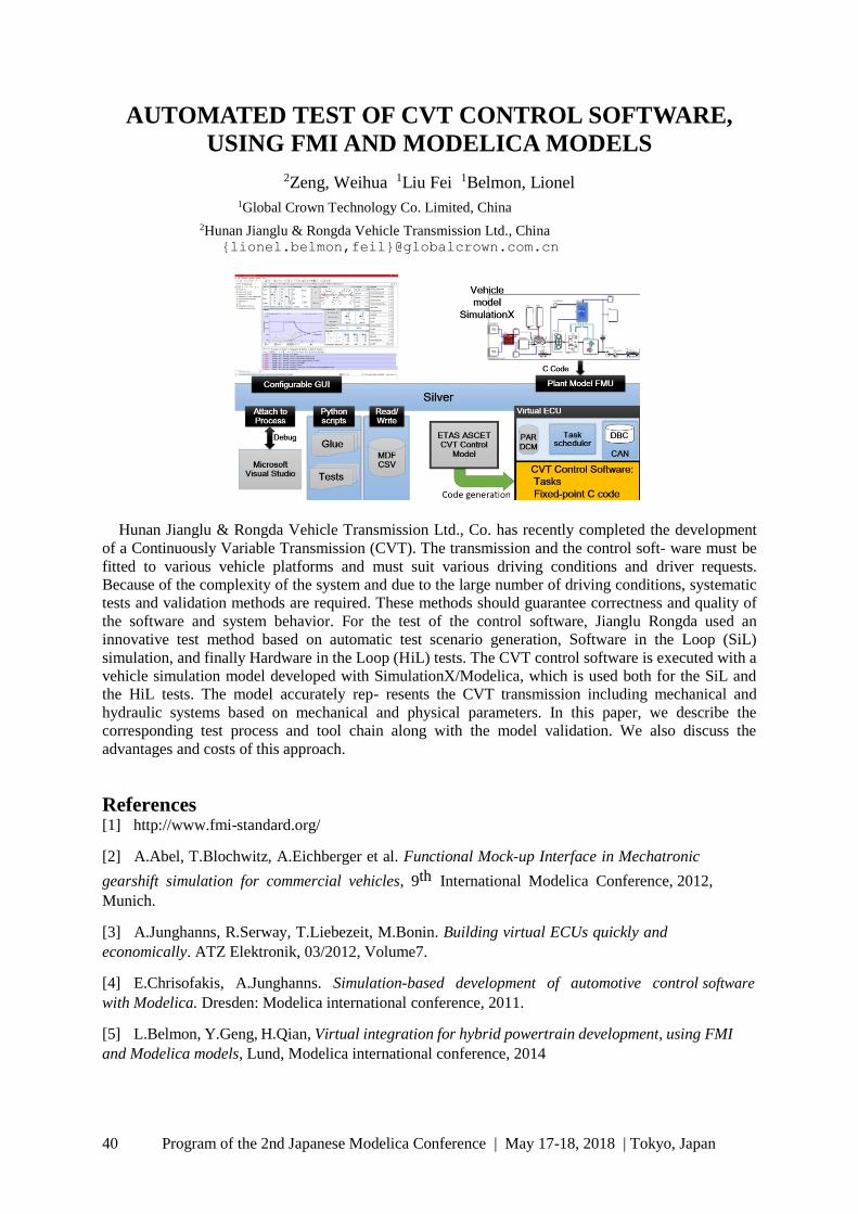
AUTOMATED TEST OF CVT CONTROL SOFTWARE,
USING FMI AND MODELICA MODELS
2Zeng, Weihua 1Liu Fei 1Belmon, Lionel 1Global Crown Technology Co. Limited, China
2Hunan Jianglu & Rongda Vehicle Transmission Ltd., China {lionel.belmon,feil}@globalcrown.com.cn
Hunan Jianglu & Rongda Vehicle Transmission Ltd., Co. has recently completed the development
of a Continuously Variable Transmission (CVT). The transmission and the control soft- ware must be
fitted to various vehicle platforms and must suit various driving conditions and driver requests.
Because of the complexity of the system and due to the large number of driving conditions, systematic
tests and validation methods are required. These methods should guarantee correctness and quality of
the software and system behavior. For the test of the control software, Jianglu Rongda used an
innovative test method based on automatic test scenario generation, Software in the Loop (SiL)
simulation, and finally Hardware in the Loop (HiL) tests. The CVT control software is executed with a
vehicle simulation model developed with SimulationX/Modelica, which is used both for the SiL and
the HiL tests. The model accurately rep- resents the CVT transmission including mechanical and
hydraulic systems based on mechanical and physical parameters. In this paper, we describe the
corresponding test process and tool chain along with the model validation. We also discuss the
advantages and costs of this approach.
References [1] http://www.fmi-standard.org/
[2] A.Abel, T.Blochwitz, A.Eichberger et al. Functional Mock-up Interface in Mechatronic
gearshift simulation for commercial vehicles, 9th International Modelica Conference, 2012,
Munich.
[3] A.Junghanns, R.Serway, T.Liebezeit, M.Bonin. Building virtual ECUs quickly and
economically. ATZ Elektronik, 03/2012, Volume7.
[4] E.Chrisofakis, A.Junghanns. Simulation-based development of automotive control software
with Modelica. Dresden: Modelica international conference, 2011.
[5] L.Belmon, Y.Geng, H.Qian, Virtual integration for hybrid powertrain development, using FMI
and Modelica models, Lund, Modelica international conference, 2014
Program of the 2nd Japanese Modelica Conference | May 17-18, 2018 | Tokyo, Japan 41
[Industrial paper] The Fault Library - A New Modelica
Library Allowing for the Systematic Simulation of Non-
Nominal System Behavior
Julia Gundermann1 Artem Kolesnikov1 Morgan Cameron2 Torsten Blochwitz1
1ESI ITI GmbH, Dresden, Germany
2ESI Group, Aix-en-Provence, France, {julia.gundermann,artem.kolesnikov,morgan.cameron,torsten.blochwitz}@esi-
group.com
To date, most Modelica libraries consider physical systems in their nominal configuration. There
have been limited attempts to extend model coverage towards behavior beyond that. These include the
Fault triggering library (van der Linden, 2014), which allows for the insertion of faults into models of
existing components; and the FAME library (de Kleer et al., 2013). The latter has served as a basis for
the development presented in the paper. The Fault library developed at ESI ITI for modeling faults
enables the user to model and simulate physical systems outside their nominal behavior in a
systematic and semiautomatic way. We outline the motivation of how and why to model faults as well
as a description of the library structure. In addition, the necessity and
implementation of helper libraries (Features, PerformanceIndicators)
and wizards (Fault Augmenter AddIn) is described.
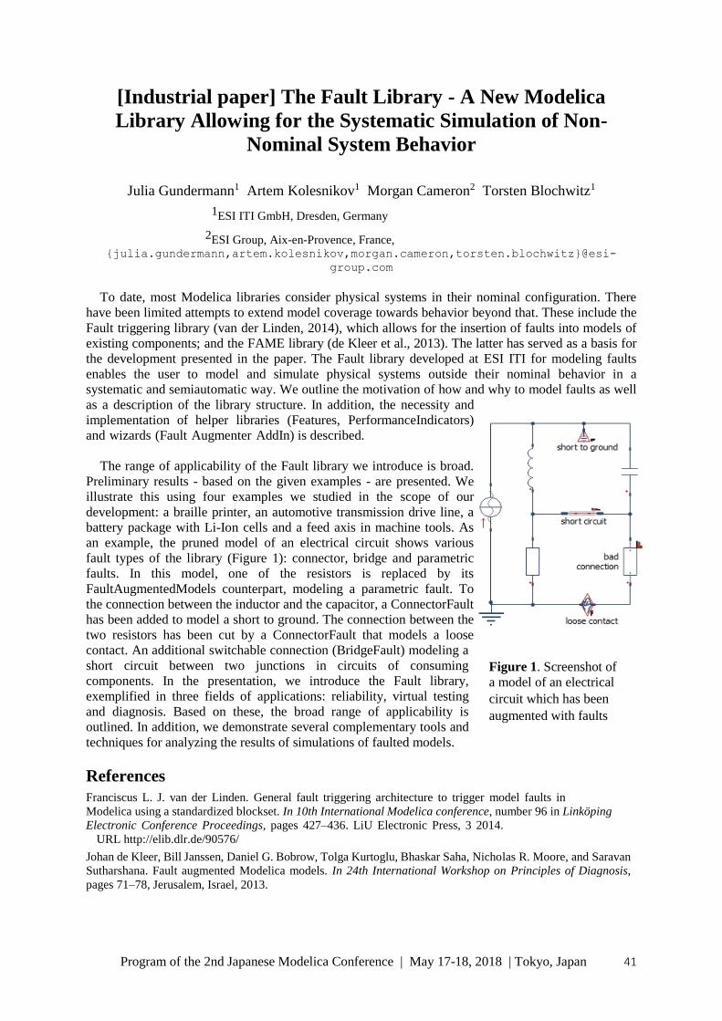
The range of applicability of the Fault library we introduce is broad.
Preliminary results - based on the given examples - are presented. We
illustrate this using four examples we studied in the scope of our
development: a braille printer, an automotive transmission drive line, a
battery package with Li-Ion cells and a feed axis in machine tools. As
an example, the pruned model of an electrical circuit shows various
fault types of the library (Figure 1): connector, bridge and parametric
faults. In this model, one of the resistors is replaced by its
FaultAugmentedModels counterpart, modeling a parametric fault. To
the connection between the inductor and the capacitor, a ConnectorFault
has been added to model a short to ground. The connection between the
two resistors has been cut by a ConnectorFault that models a loose
contact. An additional switchable connection (BridgeFault) modeling a
short circuit between two junctions in circuits of consuming
components. In the presentation, we introduce the Fault library,
exemplified in three fields of applications: reliability, virtual testing
and diagnosis. Based on these, the broad range of applicability is
outlined. In addition, we demonstrate several complementary tools and
techniques for analyzing the results of simulations of faulted models.
References Franciscus L. J. van der Linden. General fault triggering architecture to trigger model faults in
Modelica using a standardized blockset. In 10th International Modelica conference, number 96 in Linköping
Electronic Conference Proceedings, pages 427–436. LiU Electronic Press, 3 2014.
URL http://elib.dlr.de/90576/
Johan de Kleer, Bill Janssen, Daniel G. Bobrow, Tolga Kurtoglu, Bhaskar Saha, Nicholas R. Moore, and Saravan
Sutharshana. Fault augmented Modelica models. In 24th International Workshop on Principles of Diagnosis,
pages 71–78, Jerusalem, Israel, 2013.
Figure 1. Screenshot of
a model of an electrical
circuit which has been
augmented with faults

42 Program of the 2nd Japanese Modelica Conference | May 17-18, 2018 | Tokyo, Japan
[Industrial paper] Application for Optimization of Control
Parameters for Multi-body and Hydraulics System by using
FMU
Nobumasa Ishida Hideyuki Muramatsu
Dassault Systèms K.K., Japan,
[email protected], [email protected]
We developed a simulation environment using FMU (Function Mockup Unit) as performance prediction method in the early stage of development.
In this environment, hydraulic controller parts are modeled in Dymola which is one of 1D
simulation tools based on Modelica language and controlled mechanics parts are modeled in Simpack which is multibody simulation tool. We created a total system model connected to hydraulic controller parts and mechanics parts by using FMI (Function Mockup Interface). Hydraulics and controller parts are converted to FMU by Dymola, and are incorporated in Simpack mechanical model.
Furthermore, we applied the system model optimization to control parameters by using Isight.
References
[1] Dassault Systems, Dymola User Manual Volume1,2 Version 2018 (2017-04-10) [2] Dassault
Systemes Simulia Corp., Simpack Documentation Version 2018
[3] Georgia Institute of Technology, OpenHydraulics v1.0.1 (2013-02-26)

Program of the 2nd Japanese Modelica Conference | May 17-18, 2018 | Tokyo, Japan 43
Analysis of Lift-Generating Disk Type Blade Wind Power
System Using Modelica
Yeongmin Yoo1 Soyoung Lee2 Jaehyun Yoon3 Jongsoo Lee4
1Department of Mechanical Engineering, Yonsei University, Seoul, Korea,
{yym9514, leesoy77, yunjh00, jleej}@yonsei.ac.kr
This study investigated a lift-generating disk-type blade power generation mechanism that can
effectively generate wind power. The research and application technology of wind power generation
have attracted great attention in relation to the development of renewable energy. As wind power
systems such as a propeller type are being enlarged to increase power output, various problems such as
natural landscaping damage and shadow problems are occurring. Thus, we propose a lift-generating
disk type blade power generation mechanism that can effectively generate wind power even with
simple structure considering the problems of existing system. As shown in Figure 1. (a), The basic principle of the system is that vertically supported tower structures
from the ground move along the vertical axis with the disk type blade lifted by the wind. This type of
system generates electric energy through a power transmission system that converts such motion into rotary
motion along with a power conversion system, such as a generator. The proposed disk type blade has some
distinct characteristics. First, the disk can move up and down to generate lift force that is converted into
electrical energy. Second, owing to its symmetric shape, it is easily activated by the wind coming from all
directions. Finally, the proposed model has a relatively weak contibution to shadow flickering because it
does not feature multi-blade rotation and the space required for realizing its motion is comparatively small.
Figure 1. Lift-generating disk type blade wind power system. (a) Schematic diagram, (b)
Modelica simulation
The disk type blades were first designed using computer-aided design, and then they were designed
according to design parameters (Montgomery, 2017). As shown in Figure 1. (b), the modeling method
of the wind power system is explained using the Modelica (Eberhart et al, 2015). After that, a wind
tunnel test is conducted through a small scale model of the disk type blade created for simulation
verification and the results were in good agreement. As a result, the modeling of the wind power
system is verified and the results of the generator power output are presented through simulation.
References
Montgomery DC, Design and Analysis of Experiments. 9th
ed. John Wiley and Sons Press, New Jersey, 2017.
Eberhart P, Chung TS, Haumer A, and Kral C. Open Source Library for the Simulation of Wind Power Plants.
Proceedings of the 11th International Modelica Conference, September 21-23,
2015, Versailles, France.

44 Program of the 2nd Japanese Modelica Conference | May 17-18, 2018 | Tokyo, Japan
Modelling of Asymmetric Rotor and Cracked Shaft
Tatsuro Ishibashi1 Atsushi Yoshida2 Tadao Kawai2
1Meidensha Corporation, Japan, [email protected]
2Department of Mechanical & Physical Engineering, Osaka City University, Japan, [email protected], [email protected]
Rotating machinery systems have been the most important in almost all of heavy equipment such as
turbine, generator, motor and so forth. A proper modelling and simulation of rotating machinery
system with common faults should help engineers understand the performance with faults well, so that
faults can be discovered or diagnosed in the early stage. We have created the rotating machinery
library which has 5 DOF rotor dynamics model components by transfer matrix method using Modelica
(Ishibashi et al, 2017). It is suitable for modelling and simulation of rotating machinery systems with
faults. By using the Modelica_LinearSystems2 library, it is also possible to do eigenfrequency analysis
in the linearized system. This paper presents asymmetric rotor and shaft models in rotating machinery systems (Ishida and
Yamamoto, 2012). Using these models, it is possible to analyze the electrical motors or generators
which have different lateral stiffness or the moments of inertia in two orthogonal directions. The
asymmetry causes unstable vibrations in some rotating speed ranges. A cracked shaft model is
presented as the extension of the asymmetric shaft model. These models are implemented in our
original rotating machinery library.
Figure 1. Comparison of simulation results analyzed by FFT.
Blue line: Symmetrical system. Green line: Asymmetrical shaft. Red line: Cracked shaft.
The inset shows the enlarged view.
References
Tatsuro Ishibashi, Han Bing and Tadao Kawai. Rotating Machinery Library for Diagnosis. Proceedings
of the 12th International Modelica Conference, 2017. doi:10.3384/ecp17132381. Yukio Ishida and Toshio
Yamamoto. Linear and Nonlinear Rotordynamics: A Modern Treatment with Applications, 2nd Edition. Wiley-
VCH, 2012.

Program of the 2nd Japanese Modelica Conference | May 17-18, 2018 | Tokyo, Japan 45
Composable Modelling for a Hybrid Gearbox
Joshua Sutherland1 Rui Gao2
1Department of System Innovation, The University of Tokyo, Japan, [email protected]
2Modelon KK, Tokyo, Japan [email protected]
Gearbox modelling is an important topic to the simulation community due to its difficulty in
representing mixed continuous and discrete behavior. Such kind of models also usually couple the loss
of power that is dependent on the angular velocity and the load. However, one single gearbox model
with a certain fidelity cannot satisfy the broader needs to of models during product development. In
this paper, we will address hybrid modelling issues and take the gearbox model as an example to
illustrate how to model gearboxes from a Systems Engineering perspective by describing explicitly the
functionality of the gearbox (Figure 1 left) and its operational modes (Figure 1 right).
A supervisor (Figure 2 right) and supervised model structure is investigated (Figure 2 left) that
could also be regarded as a use case to a general cyber-physical modelling approach. The resultant
model achieves the same output as the LossyGear model in Modelica Standard Library.
Figure 1. Left: Describing the key aspects of a gearbox. Right: State and state transition
representation of gearbox for depicting operational modes.
Figure 2. Left: Composed gearbox model of mesh loss, bearing loss and with separate supervision
for each of those components. Right: Implementing the state transitions of Figure 1 right as
explicitly as possible.

46 Program of the 2nd Japanese Modelica Conference | May 17-18, 2018 | Tokyo, Japan
Toward the actual model exchange using FMI in practical
use cases in Japanese automotive industry
Yutaka Hirano1, Junichi Ichihara2, Haruki Saito3, Yosuke Ogata4, Takayuki Sekisue5, Satoshi
Koike6,
1 Toyota Motor Corporation, Japan {[email protected]}, 2 AZAPA Co. LTD, Japan {[email protected]},
3 Nissan Motor Corporation, Japan {[email protected]}, 4 Siemens K.K., Japan {[email protected]},
5 ANSYS Japan K.K., Japan, {[email protected]}, 6 DENSO CORPORATION{ [email protected]}
The working group in JSAE (Society of Automotive Engineers of Japan) proposed and published a
guideline about a method using adapters to enable the connection of FMUs in acausal modeling tools
in 2015. After that, more combination of exporting tools and importing tools of FMUs were tested for
the benchmark model shown in Figure 1. The success of the method was confirmed in the case of
using FMI for Model Exchange (ME). Additionally the connection of FMUs generated from various
modeling tools was tested using FMI for Co-Simulation (CS) for a full-vehicle test model shown in
Figure 2. Through the above-mentioned activities, we obtained much knowledge about utilizing FMI
for practical model exchange in the industry. Finally the requests for future realization of FMI are
described.
Figure 1. Modified benchmark model
Figure 2. Full vehicle benchmark model
References
Y. Hirano, S. Shimada, Y. Teraoka, O. Seya, Y. Ohsumi, S. Murakami, T. Hirono, T. Sekisue,
Initiatives for acausal model connection using FMI in JSAE, Proc. of the 11th International Modelica
Conference, 795-801, 2015. Doi:10.3384/ecp15118795

Program of the 2nd Japanese Modelica Conference | May 17-18, 2018 | Tokyo, Japan 47
[Industrial paper] Managing Heterogeneous Simulations
Using Architecture-Driven Design
Nico Vansina1 Bruno Loyer2 Yosuke Ogata3
1Siemens PLM Software, Belgium, [email protected]
2Siemens PLM Software, France, [email protected]
3Siemens PLM Software, Japan, [email protected]
System simulation is a proven method for anticipating the balancing of multiple performance
attributes of a product. However, in the automotive industry today, a large diversity of vehicle
architectures and technologies exists, resulting in a huge number of variants for all subsystems. It
becomes increasingly difficult to manage and analyze all possible configurations.
Additionally, subsystem models are implemented in different authoring tools. This paper presents
an architecture-driven approach to manage heterogeneous simulations. A European automotive OEM
has requested Siemens PLM Software to use its tools and process knowledge to demonstrate the
value and need for architecture-driven simulation. Simcenter System Synthesis1 was proposed as a
neutral framework for managing heterogeneous simulations. This includes three major capabilities:
Integration of different subsystem models in the form of Simcenter Amesim2
“supercomponents” and Functional Mock-up Units (FMUs) exported from Dymola3
. Plug-and-play configuration of subsystems regardless of their native software.
Performant execution of heterogeneous simulation architectures with the numerical challenges
of segregated strongly coupled systems
The focus of the project is on the process of model integration using Functional Mock- up Units
(FMUs). An electrical vehicle case-study was selected to illustrate this process.
Figure 1. Simcenter System Synthesis as a framework for managing heterogeneous simulations
1 Simcenter System Synthesis is a configuration management, system integration and system architecture management tool developed by
Siemens PLM Software 2 Simcenter Amesim is a commercial simulation software for the modeling and analysis of multi-domain systems, developed by Siemens
PLM Software 3 Dymola is a commercial modeling and simulation environment based on the open Modelica modeling language, developed by Dassault Systèmes.

48 Program of the 2nd Japanese Modelica Conference | May 17-18, 2018 | Tokyo, Japan
Simulation of high-index DAEs and ODEs with constraints
in FMI
Masoud Naja
Altair Engineering, France, ma [email protected] om
In the current FMI standard the dynamical behavior of a model can only be de ned as a system of Ordinary Differential Equations (ODE). The dynamics of many physical systems, such as the equations of motion of con- strained mechanical multibody systems, are expressed by high-index Differential Algebraic Equations (DAE) so they cannot be simulated directly using standard ODE or DAE solvers. These systems can be converted through index-reduction algorithms into ODE or index 1 DAE systems. However FMUs based solely on these latter systems suffer from drift in hidden constraints on the states. As a consequence, the simulation may results in physically meaningless solutions. In this paper, we proposed an extension of the FMI standard to handle DAE systems of index 1 or higher and ODE with constraints. In this extension, after applying an index reduction method to the high index DAE, the DAE is converted into ODE or index-1 DAE. The resulting equations is simulated using standard ODE integrators, but the solution is projected back onto the constraints after each time step. In other words, after completion of each integrator step of the ODE numerical solver, the required projection to bring back the solution on the constraints is computed, and if its norm is large enough, it is applied to the solution so that the constraints are satisfied. In this method, monitoring the magnitude of the projection and integrate it into the error control mechanism is required. This proposed FMI extension requires only few additions to the FMI specification, all of which can be omitted for FMUs that represent ODE systems or FMUs that do not support DAE handling. The extension has been implemented in solidThinking ActivateTM and two examples that show the ease of implementation and the effectiveness of the method will be discussed.
Keywords: Modelica, FMI, High index DAE, ODE with constraints, Coordinate Projection

Program of the 2nd Japanese Modelica Conference | May 17-18, 2018 | Tokyo, Japan 49
Universal Controllers for Architecture Simulation
Alexander Pollok1,2
Francesco Casella2
1DLR German Aerospace Center, Wessling, Germany
2Politecnico di Milano, Milan, Italy
[email protected], [email protected]
For optimization studies of dynamical systems, it is common practice to model and tune local
controllers for miscellaneous subsystems. For instance, a model of a chemical plant may contain a
valve motor model, and a model of a PID controller may be included to control the motor. The
associated controller tuning effort is ultimately wasted. The actual controller will be retuned anyway
after finalization of the system design, or will be structurally different.
For this reason, control algorithms are needed that just provide the functionality of the actual
control algorithm that will be designed in a later phase of the system design.
These temporary algorithms need to have low tuning requirements, and it must be possible for non-
control-specialist to generate them.
On the other hand, they only need to function inside a simulation environment.
Several mainstream control approaches are reviewed, and boundary layer sliding mode control is
proposed as a suitable approach for this kind of task. This class of controllers can be used without any
tuning effort, and is able to compete with tuned PID- controllers in terms of tracking performance.
An end-user friendly implementation of a universal controller in the equation-based and object-
oriented modelling language Modelica is presented. Several examples are shown to demonstrate the
performance of the proposed approach.

50 Program of the 2nd Japanese Modelica Conference | May 17-18, 2018 | Tokyo, Japan
Mission-Dependent Sequential Simulation for
Modeling and Trajectory Visualization of Reusable
Launch Vehicles
Lâle Evrim Briese Institute of System Dynamics and Control
DLR German Aerospace Center, Oberpfaffenhofen, Germany
The multibody modeling and visualization of reusable launch vehicles is a challenging task due to
their variable structure regarding component separation and engine cutoffs du- ring ascent and descent.
However, the number of states within a MODELICA-based multi- body model has to remain constant
during a simulation. Therefore, the variable structure of launch vehicle models is often considered by
using time- and state-dependent conditional statements and separation components. Such an approach
can lead to a higher number of equations in the model and to a higher model complexity, respectively.
In this paper, a mission-dependent sequential simulation approach for the modeling and trajectory
visualization of launch vehicle systems is introduced. Here, the system is divided into characteristic
phases, which are modeled with the DLR LauncherApplications Library capitalizing its modular,
reusable and user-friendly structure to maintain compatibility bet- ween phases and to decrease the
overall model complexity and the number of equations.
Figure 1: Overview of a Mission-Dependent Reusable Launch Vehicle Trajectory with Multiple Phases
and corresponding Visualization with the DLR Visualization Library.
References
[1] Acquatella B., P., Reiner, M. J., Modelica Stage Separation Dynamics Modeling for End-to-End
Launch Vehicle Trajectory Simulations, In Proceedings of the 10th International Modelica Conference,
2014.
[2] Briese, L. E., Schnepper, K., Acquatella B., P., Advanced Modeling and Trajectory Optimization
Framework for Reusable Launch Vehicles, In Proceedings of the IEEE Aerospace Conference (in press),
2018.
[3] Mehlhase, A., Esperon, D. G., Bergmann, J., Merkle, M., An example of beneficial use of variable-
structure modeling to enhance an existing rocket model, In Proceedings of the 10th International Modelica
Conference, 2014.

Program of the 2nd Japanese Modelica Conference | May 17-18, 2018 | Tokyo, Japan 51
Model predictive allocation control for leg-wheel
mobile robot on loose soil considering wheel
dynamics
Takatsugu Oda, Hiroki Yoshikawa, Naoki Shibata, Kenichiro Nonaka,
Kazuma Sekiguchi Tokyo City University, Japan
[email protected] [email protected] [email protected]
For the planetary exploration rover, to cope with the layer of heterogeneous superficial deposits called
regolith is important so as to achieve designed robot motion. However, the relationship between tire
and loose soil is very complex. Then, to analyze and control such kind of the effect, terramechanics is
introduced. In addition, the controlled robot in this paper has many wheel and joint; there is the
redundancy to drive. In order to optimally allocate the traction force, we propose the model predictive
allocation control. The controller adopts mod- el predictive control (MPC) that a computational cost
problem might be occurred; to avoid this problem by formulating MPC as the linear optimization
problem, we introduce the approximation model by using identification technique. Moreover, to
evaluate not only wheel motion but also robot total motion, we adopt the leg-wheel mobile robot
model previously modeled in (Yoshikawa et al., 2016); this model written by equation based language
Modelica is suitable to model and simulate complex robot, because it is not required to care about
causality of the wheel model based on terramechanics. Through the numerical simulation, we show the
suppression of superfluous slip and enhancement of traction performance.
Figure 1. The leg-wheel mobile robot described by Modelica.
References
[1] H. Yoshikawa, T. Oda, K. Nonaka, and K. Sekiguchi. Modeling and Modeling and simulation for
Leg-wheel mobile robots using Modelica. In The First Japanese Modelica Conferences, May 23-24,
Tokyo, Japan, No. 124, pp. 55–60, 2016.

52 Program of the 2nd Japanese Modelica Conference | May 17-18, 2018 | Tokyo, Japan
Generating FMUs for the Feature-Based Language Bloqqi
Niklas Fors1 Joel Petersson2 Maria Henningsson2
1Department of Computer Science, Lund University, Sweden, ni kl a s . f or s @c s . l t h. s e
2Modelon AB, Sweden, { j oe l . pe t e r s s on, ma r i a . he nni ngs s on}@mode l on. c om
In this paper, we describe how we generate C code to create Functional Mock-up Units (FMUs) for
the automation block language Bloqqi. This allows Bloqqi control programs to be tested with
simulations of the physical processes they control. The physical process can be specified in any tool
that supports the Functional Mockup-Interface (FMI) standard. For example, we have successfully run
Bloqqi programs together with Modelica models exported as FMUs (see Figures 1-3). Bloqqi
programs execute at discrete times, and we describe how this is handled in the implementation of the
DoStep function, specified in the standard.
Figure 1. Simple tank regulator in Bloqqi that controls the liquid level of a tank using two
valves: one input valve (upper Valve) and one output valve (lower Valve). The block
level Sensor reads the current liquid level. The blocks lower Valve and upper
Valve are actuators to the valves. The block RGTZ means greater than zero (for reals). The
diagram is executed periodically.
Figure 2. FMU composition in FMI Composer of the tank regulator (Figure 1) and tank
model specified in Modelica.
Figure 3. Simulation of the FMU composition in Figure 2. The set point of the liquid level is first set
to 1.8 meter and then changed to 0.2 meter.
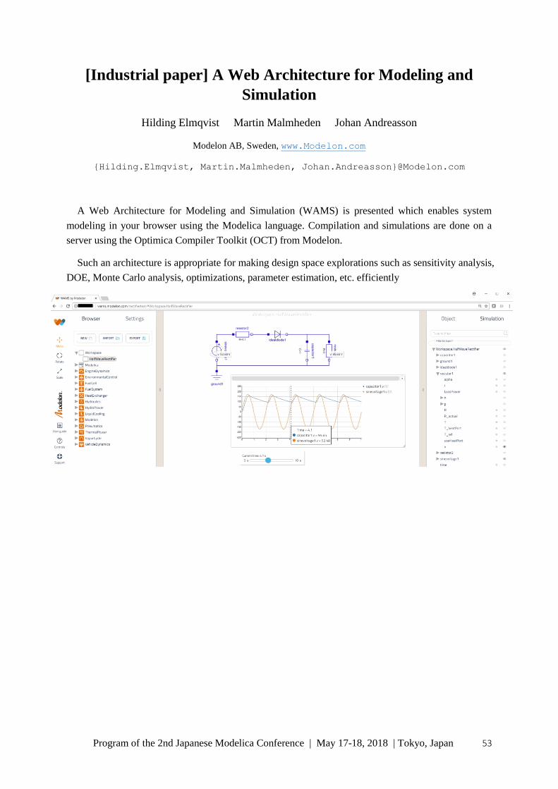
Program of the 2nd Japanese Modelica Conference | May 17-18, 2018 | Tokyo, Japan 53
[Industrial paper] A Web Architecture for Modeling and
Simulation
Hilding Elmqvist Martin Malmheden Johan Andreasson
Modelon AB, Sweden, www.Modelon.com
{Hilding.Elmqvist, Martin.Malmheden, Johan.Andreasson}@Modelon.com
A Web Architecture for Modeling and Simulation (WAMS) is presented which enables system
modeling in your browser using the Modelica language. Compilation and simulations are done on a
server using the Optimica Compiler Toolkit (OCT) from Modelon.
Such an architecture is appropriate for making design space explorations such as sensitivity analysis,
DOE, Monte Carlo analysis, optimizations, parameter estimation, etc. efficiently

54 Program of the 2nd Japanese Modelica Conference | May 17-18, 2018 | Tokyo, Japan
[Industrial paper] Multibody simulation and control of
kinematic systems with FMI/FMU
Francois Chapuis1, Jean Daniel Beley2, Stephane Garreau3, Olivier Roll4, Tim Puls5, Leon
Voss6, Sameer Kher7
1ANSYS Inc., France, [email protected] 2ANSYS Inc., France, jean-
[email protected] 3ANSYS Inc., France, [email protected] 4ANSYS Inc., France, [email protected]
5ANSYS Inc., Germany, [email protected] 6ANSYS Inc., Germany, [email protected]
7ANSYS Inc., USA, [email protected]
Our connected world and environment make us interact every day with very complex devices. Driving
our cars, monitoring health using smart phones, the extensive use of robots are all applications which
involve large quantities of embedded functions and physics. To design and simulate efficiently such
systems, individual physics simulators are not sufficient and coupled simulations are required. A new
standard called FMI (Functional Mock-Up Inter- face) [1] has been created, allowing to federate these
interactions between a wide variety of physical, digital and reduced models, either through a co-
simulation approach or through model exchange strategy using a standardized and neutral interfacing
mechanism. In this arti- cle, we illustrate through an example how it’s possible to simulate mechanical
assemblies, kinematics, dynamics and control systems in the same system model. Each mechanical
sub- assembly is represented by a FMU (Functional Mock-Up Unit) exported from a multibody
dynamics solver and includes a mix of rigid and flexible components. Flexible components are
reduced order models of the full fidelity finite element model using the well-known CMS (Component
Mode Synthesis) method. [2]
We apply the coupling through the FMI standard to a robot model, composed of rigid parts and one
flexible sub-assembly. The highly non-linear behavior of the equations of motion of the multibody
assembly is captured and consumed as a co-simulation FMU. The actuators detailed model – from the
voltage source to the electric motors – are modeled in the system simulation platform ANSYS Twin
Builder, while the control loops use SCADE which offers different control laws. The co-simulation of
these 3 sub-systems can then be performed in an efficient manner, without the prerequisite of having
on-off coupling developed between each of the individual simulators.
References
[1] fmi-standard.org
[2] Component Mode Synthesis, Jaap Wijker, in Mechanical Vibrations in Spacecraft Design, pp 369-398
Springer, Berlin, Heidelberg
[3] Nonsmooth Mechanics, Models, Dynamics and Control. Third Edition. Bernard Brogliato,
Springer, Berlin, Heidelberg

Program of the 2nd Japanese Modelica Conference | May 17-18, 2018 | Tokyo, Japan 55
[Industrial paper] Deployment process for Modelica-based
models
Takashi Iwagaya1 Chad Schmitke2 Tetsu Yamaguchi2
1Cybernet Systems Co., Ltd., Japan, [email protected]
2Maplesoft, Canada, {cschmitke,tetsuy}@maplesoft.com
This paper introduces Maplesoft’s solutions for deploying Modelica-based models for non-experts of simulation. In order to apply models to analysis, either non-experts need to learn how to use
simulation tools, or simulation experts need to prepare easy-of-use GUIs, like Excel and Web
technologies. Maplesoft’s solutions allow more flexible and rapid analysis tools development.
Maplesoft product suite can offer three types of deployment (Figure.1) :
• Case 1 : With Standalone software, MapleSim Explorer. Users need to install software
and store models and analysis tools developed by simulation experts on their own computer
• Case 2 : Web-based environment, MapleSim Server. Software, models and analysis
tools are installed on web server. Users can access analysis tools via web-browser.
• Case 3 : Cloud-based environment, MapleCloud. Analysis tools containing models are
uploaded to cloud service. Users can execute tools on cloud and download them to their own
environment appropriately.
As the fundamental capability of Maplesoft product suite, it is easy to build user- defined analysis
tools in Maple, which consist of calculation procedures and GUI, to set parameters to Modelica-based
models and apply various type of post processing with the simulation results. The analysis tools
developed in Maple can be executed in all types of deployment environment without any additional
modifications.
These solutions can realize wider adoption of Modelica-based models to increase the usage of Modelica model.
Figure 1. Three types of deployment with Maplesoft products and an example of analysis tool on
MapleCloud.
References
MapleCloud 2018: https://maple.cloud
MapleSim Explorer 2018: https://www.maplesoft.com/products/maplesimexplorer/ MapleSim Server
2018: https://www.maplesoft.com/products/maplesimserver/