the servswitch family - ftp.blackbox.comftp.blackbox.com/manuals/k/kv102a.pdf · the servswitch ™...
TRANSCRIPT
THE SERVSWITCH FAMILY
1
Welcome to the ServSwitch™ Family! Thank you for purchasing a BLACK BOX® ServSwitch™ Brand KVM switch! We appreciate your business, and we think you’ll appreciate the many ways that your new ServSwitch keyboard/video/mouse switch will save you money, time, and effort. That’s because our ServSwitch family is all about breaking away from the traditional, expensive model of computer management. You know, the one-size-fits-all-even-if-it-doesn’t model that says, “One computer gets one user station, no more, no less.” Why not a single user station (monitor, keyboard, and mouse) for multiple computers—even computers of different platforms? Why not a pair of user stations, each of which can control multiple computers? Why not multiple user stations for the same computer? With our ServSwitch products, there’s no reason why not. We carry a broad line of robust solutions for all these applications. Do you have just two PCs, and need an economical alternative to keeping two monitors, keyboards, and mice on your desk? Or do you need to share dozens of computers, including a mix of IBM® PC, RS/6000®, Apple® Macintosh®, Sun Microsystems®, and SGI® compatibles among multiple users with different access levels? Does your switch have to sit solidly on a worktable and use regular everyday cables? Or does it have to be mounted in an equipment rack and use convenient many-to-one cables? No matter how large or small your setup is, no matter how simple or how complex, we’re confident we have a ServSwitch system that’s just right for you. The ServSwitch ™ family from Black Box—the one-stop answer for all your KVM-switching needs!
* This manual will tell you all about your new ServSwitch Console Plus™, including how to install, operate, and troubleshoot it. For an introduction to the Matrix ServSwitch, see the introduction section. The ServSwitch Console Plus product codes covered in this manual are:
KV101A KV102A KV103A

SERVSWITCH™ CONSOLE PLUS
2
TRADEMARKS USED IN THIS MANUAL BLACK BOX and the logo are registered trademarks, and ServSwitch, and ServSwitch Console plus are trademarks, of Black Box Corporation. Apple, Mac, and Macintosh are registered trademarks of Apple Computer, Inc. Compaq and Alpha are registered trademarks, and DEC is a trademark, of Compaq Computer Corporation. HP is a registered trademark of Hewlett-Packard. IBM, PC/AT, PS/2, RS/6000, and ThinkPad are registered trademarks, and PC/XT is a trademark, of International Business Machines Corporation. Microsoft, HyperTerminal, IntelliMouse, Windows, and Windows NT are registered trademarks or trademarks of Microsoft Corporation in the United States and/or other countries. Sun and Sun Microsystems are registered trademarks of Sun Microsystems, Inc. in the United States and other countries. Any other trademarks mentioned in this manual are acknowledged to be the property of the trademark owners.
FCC/IC STATEMENTS
3
3ARATION OF CONFORMITY FEDERAL COMMUNICATIONS COMMISSION AND INDUSTRY CANADA
RADIO-FREQUENCY INTERFERENCE STATEMENTS
This equipment generates, uses, and can radiate radio frequency energy and if not installed and used properly, that is, in strict accordance with the manufacturer’s instructions, may cause interference to radio communication. It has been tested and found to comply with the limits for a Class A computing device in accordance with the specifications in Subpart B of Part 15 of FCC rules, which are designed to provide reasonable protection against such interference when the equipment is operated in a commercial environment. Operation of this equipment in a residential area is likely to cause interference, in which case the user at his own expense will be required to take whatever measures may be necessary to correct the interference. Changes or modifications not expressly approved by the party responsible for compliance could void the user’s authority to operate the equipment. 4 MATRIX SERVSWITCH™

SERVSWITCH™ CONSOLE PLUS
4
EUROPEAN UNION DECLARATION OF CONFORMITY This equipment complies with the requirements of the European EMC Directive 89/336/EEC with respect to EN55022 (Class B), EN50082-1/EN60555-2 and the Low Voltage Directive.
CE
NOM STATEMENT
5
5 NOM STATEMENT
NORMAS OFICIALES MEXICANAS (NOM) ELECTRICAL SAFETY STATEMENT
INSTRUCCIONES DE SEGURIDAD
1. Todas las instrucciones de seguridad y operación deberán ser leídas antes de
que el aparato eléctrico sea operado.
2. Las instrucciones de seguridad y operación deberán ser guardadas para referencia futura. 3. Todas las advertencias en el aparato eléctrico y en sus instrucciones de operación deben ser respetadas. 4. Todas las instrucciones de operación y uso deben ser seguidas. 5. El aparato eléctrico no deberá ser usado cerca del agua—por ejemplo, cerca de la tina de baño, lavabo, sótano mojado o cerca de una alberca, etc. 6. El aparato eléctrico debe ser usado únicamente con carritos o pedestales que sean recomendados por el fabricante. 7. El aparato eléctrico debe ser montado a la pared o al techo sólo como sea recomendado por el fabricante. 8. Servicio—El usuario no debe intentar dar servicio al equipo eléctrico más allá a lo descrito en las instrucciones de operación. Todo otro servicio deberá ser referido a personal de servicio calificado. 9. El aparato eléctrico debe ser situado de tal manera que su posición no interfiera su uso. La colocación del aparato eléctrico sobre una cama, sofá, alfombra o superficie similar puede bloquea la ventilación, no se debe colocar en libreros o gabinetes que impidan el flujo de aire por los orificios de ventilación. 10. El equipo eléctrico deber ser situado fuera del alcance de fuentes de calor como radiadores, registros de calor, estufas u otros aparatos (incluyendo amplificadores) que producen calor. 11. El aparato eléctrico deberá ser connectado a una fuente de poder sólo del tipo descrito en el instructivo de operación, o como se indique en el aparato.
SERVSWITCH™ CONSOLE PLUS
6
12. Precaución debe ser tomada de tal manera que la tierra fisica y la polarización del equipo no sea eliminada. 13. Los cables de la fuente de poder deben ser guiados de tal manera que no sean pisados ni pellizcados por objetos colocados sobre o contra ellos, poniendo particular atención a los contactos y receptáculos donde salen del aparato. 14. El equipo eléctrico debe ser limpiado únicamente de acuerdo a las recomendaciones del fabricante. 15. En caso de existir, una antena externa deberá ser localizada lejos de las lineas de energia. 16. El cable de corriente deberá ser desconectado del cuando el equipo no sea usado por un largo periodo de tiempo. 17. Cuidado debe ser tomado de tal manera que objectos liquidos no sean derramados sobre la cubierta u orificios de ventilación. 18. Servicio por personal calificado deberá ser provisto cuando: A: El cable de poder o el contacto ha sido dañado; u B: Objectos han caído o líquido ha sido derramado dentro del aparato; o C: El aparato ha sido expuesto a la lluvia; o D: El aparato parece no operar normalmente o muestra un cambio en su desempeño; o E: El aparato ha sido tirado o su cubierta ha sido dañada.
INTRODUCTION
7
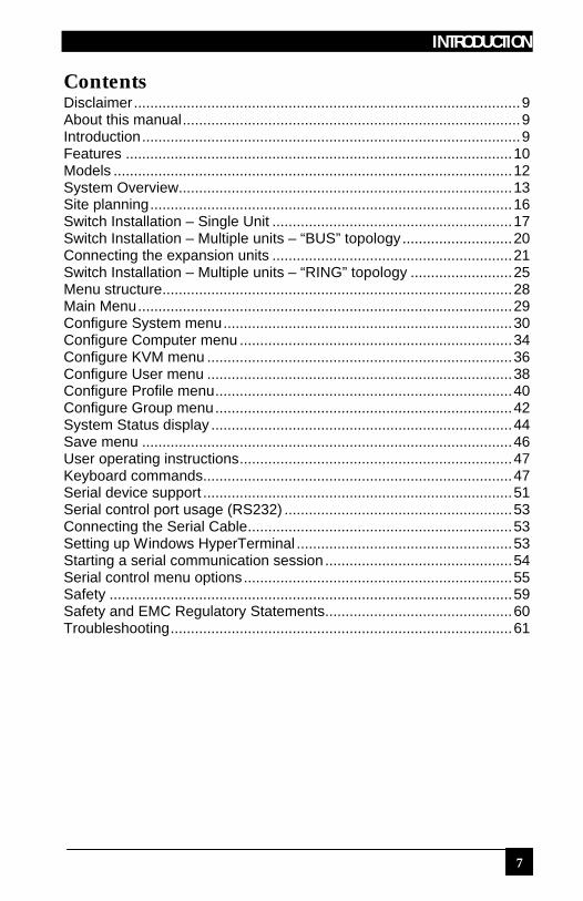
Contents Disclaimer...............................................................................................9 About this manual...................................................................................9 Introduction.............................................................................................9 Features ...............................................................................................10 Models ..................................................................................................12 System Overview..................................................................................13 Site planning.........................................................................................16 Switch Installation – Single Unit ...........................................................17 Switch Installation – Multiple units – “BUS” topology...........................20 Connecting the expansion units ...........................................................21 Switch Installation – Multiple units – “RING” topology .........................25 Menu structure......................................................................................28 Main Menu............................................................................................29 Configure System menu.......................................................................30 Configure Computer menu ...................................................................34 Configure KVM menu ...........................................................................36 Configure User menu ...........................................................................38 Configure Profile menu.........................................................................40 Configure Group menu.........................................................................42 System Status display ..........................................................................44 Save menu ...........................................................................................46 User operating instructions...................................................................47 Keyboard commands............................................................................47 Serial device support ............................................................................51 Serial control port usage (RS232) ........................................................53 Connecting the Serial Cable.................................................................53 Setting up Windows HyperTerminal .....................................................53 Starting a serial communication session ..............................................54 Serial control menu options..................................................................55 Safety ...................................................................................................59 Safety and EMC Regulatory Statements..............................................60 Troubleshooting....................................................................................61
SERVSWITCH™ CONSOLE PLUS
8
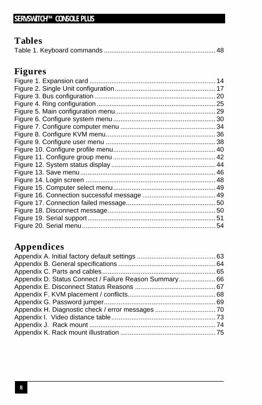
Tables Table 1. Keyboard commands ............................................................. 48 Figures Figure 1. Expansion card ..................................................................... 14 Figure 2. Single Unit configuration ....................................................... 17 Figure 3. Bus configuration .................................................................. 20 Figure 4. Ring configuration ................................................................. 25 Figure 5. Main configuration menu....................................................... 29 Figure 6. Configure system menu ........................................................ 30 Figure 7. Configure computer menu .................................................... 34 Figure 8. Configure KVM menu............................................................ 36 Figure 9. Configure user menu ............................................................ 38 Figure 10. Configure profile menu........................................................ 40 Figure 11. Configure group menu ........................................................ 42 Figure 12. System status display ......................................................... 44 Figure 13. Save menu.......................................................................... 46 Figure 14. Login screen ....................................................................... 48 Figure 15. Computer select menu........................................................ 49 Figure 16. Connection successful message ........................................ 49 Figure 17. Connection failed message................................................. 50 Figure 18. Disconnect message........................................................... 50 Figure 19. Serial support ...................................................................... 51 Figure 20. Serial menu......................................................................... 54 Appendices Appendix A. Initial factory default settings ........................................... 63 Appendix B. General specifications ..................................................... 64 Appendix C. Parts and cables.............................................................. 65 Appendix D. Status Connect / Failure Reason Summary.................... 66 Appendix E. Disconnect Status Reasons ............................................ 67 Appendix F. KVM placement / conflicts................................................ 68 Appendix G. Password jumper............................................................. 69 Appendix H. Diagnostic check / error messages ................................. 70 Appendix I. Video distance table......................................................... 73 Appendix J. Rack mount ..................................................................... 74 Appendix K. Rack mount illustration .................................................... 75

INTRODUCTION
9
Disclaimer While every precaution has been taken in the preparation of this manual, the manufacturer assumes no responsibility for errors or omissions. Neither does the manufacturer assume any liability for damages resulting from the use of the information contained herein. The manufacturer reserves the right to change the specifications, functions, or circuitry of the product without notice. The manufacturer cannot accept liability for damages due to misuse of the product or other circumstances outside the manufacturer’s control. The manufacturer will not be responsible for any loss, damage, or injury arising directly or indirectly from the use of this product.
About this manual This manual covers the installation and operations of the ServSwitch Console Plus switches.
Introduction Thank you for choosing a ServSwitch Console Plus™. Designed with your needs in mind, your new switch will simplify your job by helping you organize your multiple-computer application. Its use in large computer facilities gives the IT professional the added flexibility to monitor and maintain hundreds of systems, running on different platforms, from a central location. The ServSwitch Console Plus is the common sense switching solution that provides the flexibility, integrity, and security required for today’s business environment. The advanced On-Screen-Display (OSD) menus guide you through the configuration process with on-screen information for each configuration section, making it easy to configure the ServSwitch Console Plus, the KVM station, the computers, and security for the system. There are also additional configuration parameters that can be used to personalize the look of the menus and dialog boxes. A help line is provided for each menu selection giving a brief explanation of the selected menu item. ServSwitch Console Plus is designed to meet your switching needs, whatever your system demands are, one computer or hundreds. All models offer standard features that allow for easy, secure, and complete access to as many as 1,000 computers from a single user KVM station. Reliability, security, flash memory technology, and other features ensure the ServSwitch Console Plus switch will streamline your data center or server room and simplify the maintenance, access, and updating of your systems.
NOTE: A Keyboard, Video monitor, and Mouse are referred to throughout this manual as a KVM station.
SERVSWITCH™ CONSOLE PLUS
10
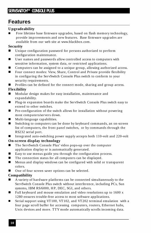
Features Upgradeability n Free lifetime base firmware upgrades, based on flash memory technology,
provide improvements and new features. Base firmware upgrades are available from our web site at www.blackbox.com.
Security n Unique configuration password for persons authorized to perform
configuration maintenance. n User names and passwords allow controlled access to computers with
sensitive information, system data, or restricted applications. n Computers can be assigned to a unique group, allowing authorized access. n Four connect modes: View, Share, Control and Private provide flexibility
in configuring the ServSwitch Console Plus switch to conform to your security requirements.
n Profiles can be defined for the connect mode, sharing and group access. Flexibility n Modular design makes for easy installation, maintenance and
expandability. n Plug-in expansion boards make the ServSwitch Console Plus switch easy to
extend to other switches. n Pre-configuration of the switch allows for installation without powering
most computers/servers down. n Multi-language capabilities. n Switching to computers can be done by keyboard commands, an on-screen
list of computers, the front panel switches, or by commands through the RS232 serial port.
n Integrated auto-switching power supply accepts both 110-volt and 220-volt On-screen display technology n The ServSwitch Console Plus’ video pops-up over the computer
application display or is automatically generated. n Easy to use menus guide you through the configuration process. n The connection status for all computers can be displayed. n Menus and display windows can be configured with solid or transparent
colors. n One of four screen saver options can be selected. Compatibility n A variety of hardware platforms can be connected simultaneously to the
ServSwitch Console Plus switch without interference, including PCs, Sun systems, IBM RS/6000, HP, DEC, SGI, and others.
n Full keyboard and mouse emulation and video resolutions up to 1600 x 1280 ensures trouble-free access to most software applications.
n Serial support using VT100, VT102, and VT202 terminal emulation with a four page scroll buffer for accessing computers, routers, Ethernet hubs, Unix devices and more. TTY mode automatically scrolls incoming data.
INTRODUCTION
11
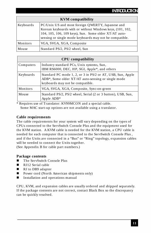
CPU compatibility
Computers Industry standard PCs, Unix systems, Sun, IBM RS6000, DEC, HP, SGI, Apple*, and others
Keyboards Standard PC mode 1, 2, or 3 in PS/2 or AT, USB, Sun, Apple ADB*, Some older XT/AT auto-sensing or single mode keyboards may not be compatible.
Monitors VGA, SVGA, XGA, Composite, Sync-on-green
Mouse Standard PS/2, PS/2 wheel, Serial (2 or 3 button), USB, Sun, Apple ADB*
* Requires use of Translator: KV99MCON and a special cable. Some MAC start-up options are not available using a translator. Cable requirements The cable requirements for your system will vary depending on the types of CPUs connected to the ServSwitch Console Plus and the equipment used for the KVM station. A KVM cable is needed for the KVM station, a CPU cable is needed for each computer that is connected to the ServSwitch Console Plus , and if the Units are connected in a “Bus” or “Ring” topology, expansion cables will be needed to connect the Units together. (See Appendix B for cable part numbers.) Package contents n The ServSwitch Console Plus n RJ12 Serial cable n RJ to DB9 adapter n Power cord (North American shipments only) n Installation and operations manual CPU, KVM, and expansion cables are usually ordered and shipped separately. If the package contents are not correct, contact Black Box so the discrepancy can be quickly resolved.
KVM compatibility Keyboards PC/Unix US and most foreign QWERTY, Japanese and
Korean keyboards with or without Windows keys, (101, 102, 104, 105, 106, 109 keys), Sun. Some older XT/AT auto-sensing or single mode keyboards may not be compatible.
Monitors VGA, SVGA, XGA, Composite
Mouse Standard PS/2, PS/2 wheel, Sun

SERVSWITCH™ CONSOLE PLUS
12
Models
ServSwitch Console Plus Models
ServSwitch Console plus rear panel Model number
KV101A
KV102A
KV103A
Connector Description
IEC320 power connector
Optional expansion connectors (HD15M/F) (Part number SW740C-R3-B)
CPU connectors (DB25F)
KVM connector (DB25F)
Serial connector (RJ12 – 6 pin)
OVERVIEW
13
System Overview The ServSwitch Console Plus is designed with the latest in KVM switching technology. It has the capability and flexibility to configure to most keyboards, video monitors, mice, servers and computers. The modular design of the ServSwitch Console Plus makes the Unit easy to install, expand, and maintain. The addition of an expansion card and additional switches can increase the number of computers that can be connected and accessed to 1,000. The ServSwitch Console Plus series switches are available in three configurations depending on your system switching needs, 4, 8, or 16 CPU ports and one KVM port. KVM station A KVM station, consisting of a Keyboard, Video monitor, and Mouse, connects to the DB25F KVM connector on the rear panel using a KVM adapter cable. The KVM adapter cable is available with a variety of connector types to accommodate the different types of keyboards, video monitors, and mice. The KVM adapter cable connectors must be compatible with the keyboard, video monitor, and mouse cable connectors. KVM adapter cables are available in lengths of 1 – 100 feet. (Refer to the compatibility table on page 11) KVM Station Keyboard and Mouse Can use a PS/2 keyboard and mouse or a Sun Keyboard and Mouse. Note: When using a PS/2 keyboard, the PS/2 keyboard must be capable of
communicating in Mode 2 and Mode 3 if the CPU's are PC Mode 3, USB, SUN, or a translator is used with an Apple computer.
KVM Station Video Monitor The KVM Station video monitor must be capable of supporting the resolution, frequency, and sync type being sent by all connected computer. It is recommended that the KVM monitor be a multi-sync monitor capable of resolutions up to 1280 x 1024 @ 75Hz or better. The quality of the video depends largely on the type of monitor used, the KVM cable length and cable type. For cable lengths greater than 20 feet, coax cable must be used. Appendix I. shows the video quality distance table for different cable types. Computers The ServSwitch Console Plus can connect to PC’s, Unix systems, Sun systems, and USB. Apple ADB computers can be connected using a translator. The CPU connectors on all models are DB25F. Each connected computer uses a CPU adapter cable compatible with the computer’s keyboard, monitor, and mouse ports. (available in lengths of 5 – 100 feet).

SERVSWITCH™ CONSOLE PLUS
14
The ServSwitch Console Plus can support computers and serial devices such as routers and hubs, which require a serial interface. A special cable is used to connect from the ServSwitch Console Plus CPU connectors (DB25F) to a serial interface (Dumb Terminal, CPU, or serial device). The ServSwitch Console Plus CPU port must first be configured for serial functions. Serial CPU cables are available in DB25 to: n DB9 n DB25 n RJ11 n RJ12 n RJ45 n MD8
Expansion To expand the ServSwitch Console Plus in a Bus or Ring configuration, an expansion card must be installed in each ServSwitch Console Plus. Figure 1 shows the expansion card used for all models. (Part number SW740C-R3-B) The expansion connectors provide the means of sending the system, keyboard, video, and mouse data from one expansion card output to another expansion card input. This allows a KVM station on one ServSwitch Console Plus to connect to a computer connected on another switch. Expansion cables are needed for each expansion Unit. Expansion cables are available in lengths of 2 – 100 feet. If an expansion card is permanently removed, a terminator and cover plate must be installed.
Part number SW740C-R3-B
Figure 1. Expansion card To remove the expansion card and install/remove jumper JP1: 1. Remove power from the ServSwitch Console Plus. 2. Remove any expansion cables. 3. Unscrew the two screws securing the expansion card to the chassis. 4. Carefully pull the expansion card straight back until it unseats
from the backplane connector. 5. Remove/install the jumper JP1, on the expansion cards.
(See Bus or Ring installation section for jumper removal/installation) 6. Re-install the expansion card. Make sure it seats properly in the
backplane connector. 7. Secure the expansion card with the two screws. 8. Replace any expansion cables
IN
OUT
JP1

OVERVIEW
15
RS232 port All ServSwitch Console Plus models are equipped with an RS232 serial port. This port on all models is an RJ12, 6-conductor connector. It provides a serial interface to the ServSwitch Console Plus from a computer terminal, a standalone computer or a Notebook computer that is not connected to a CPU port on the Unit. The RS232 serial port enables you to: n Upgrade the system firmware n Restore a Unit to its factory default settings n Configure an expansion switch (alternative method) n Switch a KVM station to a CPU port An adapter and serial cable are provided for serial interface. Firmware cannot be updated from a computer terminal. Cabling A KVM station, computers and servers are easily connected to the ServSwitch Console Plus with the proper cables. Provide adequate strain relief for the CPU, KVM, and expansion cables to relieve excess tension on the connectors. System security Security is a very important concern especially in the environment most ServSwitch Console Plus are commonly installed in, such as data centers and server rooms. The ServSwitch Console Plus can be secured with a unique configuration password allowing only authorized personnel access to the menus and the system set-up functions, including creating and assigning users, groups, and profiles. The KVM station can also be secured by assigning user access names and passwords that restrict access to certain computers or servers that contain sensitive information or restricted applications. Other security functions include the flexibility of assigning certain computers to a unique Group. This feature allows you to group computers together for access by defined “Profiles”. These profiles can be set-up to define the way computers within a “Group” are accessed. The security functions, “Users”, “Profiles”, and “Groups” are configured from the main configuration menu and when set-up, form a flexible, reliable, and secure system. These functions are explained in detail in the menu section and the site planning section.
Avoid routing cables close to fluorescent lights, air compressors, high voltage power sources and machinery that may create electrical noise or interference that may interfere with the operation of the ServSwitch Console Plus.

SERVSWITCH™ CONSOLE PLUS
16
Site planning Organizing your site and planning the placement of the computers, the KVM station, and the ServSwitch Console Plus is a key part in the installation and configuration process. Care should be taken when connecting the computers, KVM and the ServSwitch Console Plus . Locate the ServSwitch Console Plus as close as possible to the computers so the cables are as short as possible but still give some freedom of movement. Using shorter cables keeps the video noise to a minimum and reduces installation costs. Provide proper strain relief for all cables. The ServSwitch Console Plus can be rack mounted with a rack mount kit (see Appendix J & K). Wherever the ServSwitch Console Plus is located, it should be on a secure surface, free from obstructions and objects that may cause damage to the Unit or an individual. Following are a few items to consider prior to installing or configuring the ServSwitch Console Plus switch: n Identify the computers that do not use a PC2 type keyboard and a PS/2
mouse (default settings). Before connecting these computers to a CPU port, the CPU port must be pre-configured to change the default keyboard and mouse types to the correct types.
n Each computer can be assigned a unique computer name. Names like staff, marketing, and finance make it easy to identify and connect to. The default computer names are Computer x (x = 1 – 1,000)
n The KVM station can also be assigned a unique KVM name. The default KVM name is KVM station 1
n Access to the system set-up and configuration can be limited by assigning a configuration password.
n Access to the computers can be limited by assigning each user a unique user ID and password and configuring the switch to require a login.
n Pre-plan the expansion cable routing for expanded systems. The configuration of the system, computers, KVM stations, users, profiles, and groups are defined in the menu section.
INSTALLATION
17
Switch Installation – Single Unit
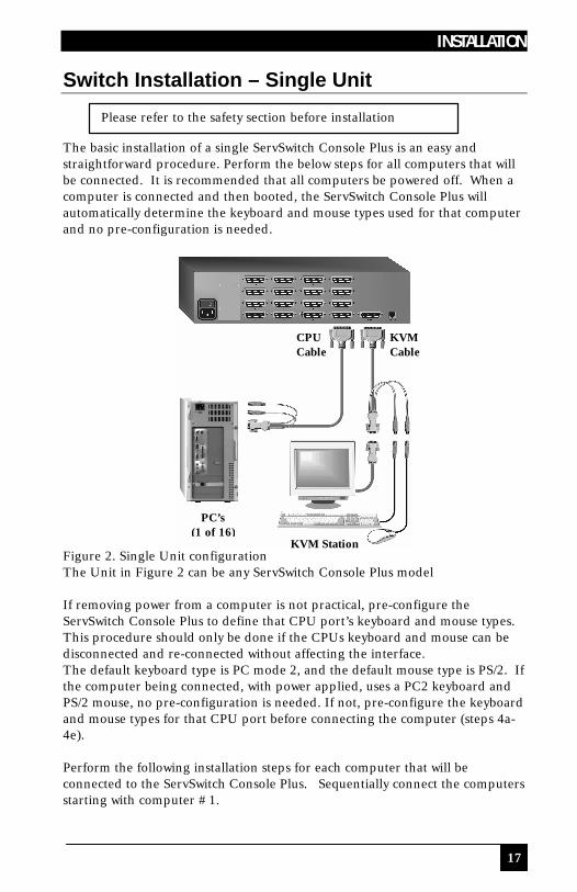
The basic installation of a single ServSwitch Console Plus is an easy and straightforward procedure. Perform the below steps for all computers that will be connected. It is recommended that all computers be powered off. When a computer is connected and then booted, the ServSwitch Console Plus will automatically determine the keyboard and mouse types used for that computer and no pre-configuration is needed.
Figure 2. Single Unit configuration The Unit in Figure 2 can be any ServSwitch Console Plus model If removing power from a computer is not practical, pre-configure the ServSwitch Console Plus to define that CPU port’s keyboard and mouse types. This procedure should only be done if the CPUs keyboard and mouse can be disconnected and re-connected without affecting the interface. The default keyboard type is PC mode 2, and the default mouse type is PS/2. If the computer being connected, with power applied, uses a PC2 keyboard and PS/2 mouse, no pre-configuration is needed. If not, pre-configure the keyboard and mouse types for that CPU port before connecting the computer (steps 4a-4e). Perform the following installation steps for each computer that will be connected to the ServSwitch Console Plus. Sequentially connect the computers starting with computer #1.
Please refer to the safety section before installation
KVM Station
CPU Cable
KVM Cable
PC’s (1 of 16)

SERVSWITCH™ CONSOLE PLUS
18
STEPS: (See Figure 2 for an example of a single Unit installation) (Refer to the troubleshooting section for help if needed) 1. Connect a KVM station to the ServSwitch Console Plus DB25F, KVM
connector using the appropriate KVM cable. 2. Turn on the KVM stations video monitor and the ServSwitch Console Plus.
(Wait for the internal diagnostic check to complete and fade out) 3. Switch the KVM station to the CPU port being configured (starting with
CPU port #1). This is done by pressing and releasing the left control [Ctrl] key and within 2 seconds, type in the CPU port # being configured (starting with port 1) and press [Enter]. A connection dialog box will display showing the connection status. (Figure 17) (See Note below on switching methods)
4. Pre-configure the CPU port, if needed, as outlined in steps 4a-e if the computer being connected does not use a PC2 type keyboard or a PS/2 mouse (defaults). Pre-configure the CPU port before connecting the computer. If the computer uses a PC2 type keyboard and PS/2 mouse, connect it to the corresponding CPU port. No pre-configuration is needed.
Pre-Configuration procedure Call up the Configuration menu system by pressing and releasing the left [Ctrl] key, then the [F12] key. (Figure 5)
a. Select “Computer” and press [Enter] (Figure 7) b. Select the computer to change the default keyboard and/or mouse type,
and then select the keyboard or mouse field for the selected computer and press [Enter]. A selection box will display, listing the supported keyboard or mouse types.
c. Select the correct keyboard or mouse type for the selected computer and press [Enter].
d. Press [ESC] to return to the “Main menu” and save the changes. e. Connect the computer to the pre-configured CPU port.
5. Boot the computer the KVM station is connected to if the computer power was off. You should see the boot up sequence on the KVM monitor. If the computer was connected to a pre-configured CPU port with power applied, you should see that computers video.
6. Verify that the keyboard, video, and mouse on the connected computer function properly before proceeding.
7. Switch the KVM station to the next sequential CPU port as explained in step 3 and perform steps 4-6 for that computer and for the remaining computers.
NOTE: Switching CPU ports can also be performed by pressing the
“+ “ or “- “ select buttons on the front panel. “+” will switch to the next sequential CPU port, “- “ will switch to the previous CPU port. The connection dialog message will display after pressing either button showing which CPU port is connected.

INSTALLATION
19
8. When all computers are connected and operating properly, change the “Maximum computers” value from the default value of 64 to the correct number of computers connected to the single Unit. This will limit the scanning function to the actual number of computers that are connected. Change the “Maximum computers” value as follows: (See page 15 for determining the “Maximum computers” value.) a. Call up the main menu ([Ctrl], F12). (Figure 5) b. Select “System” and press [Enter]. (Figure 6) c. Select “Maximum computers” and press [Enter]. d. Enter the correct “Maximum computers” value and press [Enter]. e. Press [ESC] to return to the main menu. f. Save the changes and EXIT. (Figure 14)
This completes the basic installation for a single Unit. You can switch to any of the attached computers from the keyboard by pressing and releasing the left control [Ctrl] key, typing in the computer port number to switch to and press [Enter]. You can also switch to a computer by displaying the “Computer select” menu (left control [Ctrl] key, then press the [ESC] key). Select the computer to switch to from the list and press [Enter]. You will be immediately switched to that computer. (Figure 16). To customize the configuration settings for the system, computers, KVM stations, users, profiles, groups, and language see the Configuration Menu section for details. Refer to the Operation section for information on the operation of the ServSwitch Console Plus.
SERVSWITCH™ CONSOLE PLUS
20
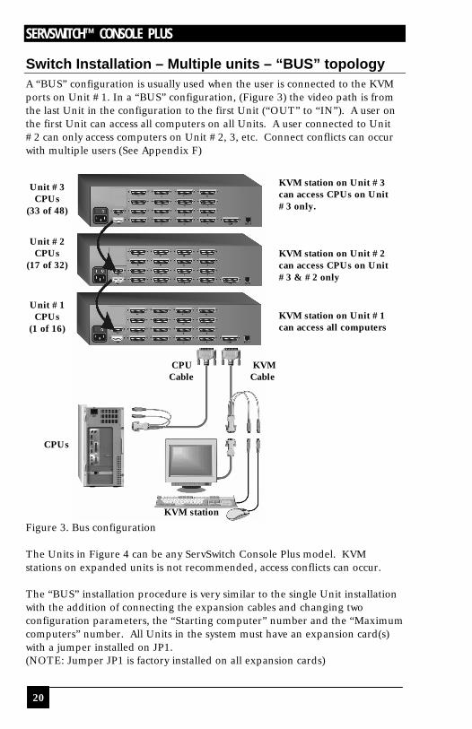
Switch Installation – Multiple units – “BUS” topology A “BUS” configuration is usually used when the user is connected to the KVM ports on Unit #1. In a “BUS” configuration, (Figure 3) the video path is from the last Unit in the configuration to the first Unit (“OUT” to “IN”). A user on the first Unit can access all computers on all Units. A user connected to Unit #2 can only access computers on Unit #2, 3, etc. Connect conflicts can occur with multiple users (See Appendix F)
Figure 3. Bus configuration The Units in Figure 4 can be any ServSwitch Console Plus model. KVM stations on expanded units is not recommended, access conflicts can occur. The “BUS” installation procedure is very similar to the single Unit installation with the addition of connecting the expansion cables and changing two configuration parameters, the “Starting computer” number and the “Maximum computers” number. All Units in the system must have an expansion card(s) with a jumper installed on JP1. (NOTE: Jumper JP1 is factory installed on all expansion cards)
Unit #1 CPUs
(1 of 16)
KVM station
KVM station on Unit #3 can access CPUs on Unit #3 only. KVM station on Unit #2 can access CPUs on Unit #3 & #2 only KVM station on Unit #1 can access all computers
Unit #2 CPUs
(17 of 32)
Unit #3 CPUs
(33 of 48)
CPU Cable
KVM Cable
CPUs

INSTALLATION
21
To start, identify the following prior to installation: 1. Which ServSwitch Console Plus will be #1, #2, and so on. 2. Which computer will be #1, #2, and so on. 3. Which computers do not use a PC2 keyboard or a PS/2 mouse. 4. Which Unit and CPU port each computer will be connected to. 5. The “Starting computer” number for each Unit. 6. The number of computers, or “Maximum computers”, that the ServSwitch
Console Plus will be managing. The “Starting computer” and “Maximum computers” values are determined as follows: Starting computer The “Starting computer” number will depend on which Unit is being configured. The “Starting computer” number for the first Unit is always one (default). Using Units that have 16 CPU ports, the “Starting computer” number for the second Unit is the total number of CPU ports on the first Unit + one or 17, the third Unit would have a “Starting computer” number of 33 (Total CPU ports on unit #1 and unit #2 + 1, and so on. Maximum computers The “Maximum computers” value is calculated by counting the total number of CPU ports on all units. If your system consists of 10 ServSwitch Console Plus Units, each with 16 CPU ports, the “Maximum computers” number would be 160. The “Maximum computers” value must be entered from a KVM station and when saved, this value is propagated to all connected Units. Connecting the expansion units The installation steps below are for all ServSwitch Console Plus models. (NOTE: Expansion cables should not be connected at this point) Steps: 1. Verify that power is “OFF” on all ServSwitch Console Plus switches. 2. Configure the “Starting computer” number for all the ServSwitch Console
Plus switches, starting with Unit #2 by: (Unit #1 default = 1) a. Connect a KVM station to Unit #2’s KVM connector using the
appropriate KVM adapter cable. b. Apply power to the KVM monitor and to ServSwitch Console Plus #2. c. When the internal diagnostic completes, press and release the left
control [Ctrl] key, then the F12 key to display the “Main menu”. d. Select “System” and press [Enter].
e. Next, select “Starting computer number” and press [Enter]. An input box will display for a new starting computer number. Enter the correct “Starting computer” number for this Unit (See page 15) and press [Enter]. Press the “Esc” key to return to the “Main menu”.

SERVSWITCH™ CONSOLE PLUS
22
f. Select “Save” and press [Enter]. A “YES/NO” choice box will display. Select “YES” and press [Enter] to save the changes.
g. Turn the power off on the ServSwitch Console Plus. h. Connect the KVM station to the KVM connector on Unit #3. i. Configure this Units “Starting computer” number and then all other
Units in the system. When the “Starting computer” number has been entered for all Units, proceed to step 3.
3. Connect the KVM station to Unit #1’s KVM connector and apply power to the monitor and Unit #1.
4. Enter the “Maximum computers” number a. Display the main menu (left control [Ctrl] key, then the F12 key.) b. Select “System” and press [Enter]. c. Select “Maximum computers” and press [Enter]. An input box will
display for a new “Maximum computers” number. Enter the correct “Maximum computers” value as explained on page 15 and press [Enter].
d. Press the “Esc” key to return to the “Main menu”, select “Save” and press [Enter]. A “YES/NO” choice box will display. Select “YES” and press [Enter] to save the change.
5. The next item is to connect the Units in a “BUS” configuration and verify that communication between the Units is established. To do this, call up the System status display by pressing and releasing the left control [Ctrl] key, then the F12 key.
6. Select “Status” from the Main menu and press [Enter]. The system status screen will display showing the following: (Figure 13) a. Computers b. Power (Power on status) c. POS (Card position) d. VER (Program version) e. KVM f. CPU g. User h. Status The number of system CPU ports that Unit #1 has will be highlighted. If the Unit is a 16-port switch, computers 1–4, 5–8, 9–12, and 13–16 will be highlighted on the status screen.
7. Apply power to the next unit to bus in, then connect an expansion cable (IN THIS ORDER); From: Unit #2’s “OUT” expansion card connector To: Unit #1’s “IN” expansion card connector. (Connecting the expansion cable from the “IN” connector first to the “OUT” connector can cause termination conflicts and require power to be cycled on all units.

INSTALLATION
23
8. Verify that the block of system CPU ports from Unit #2 is recognized on
the status screen. If Unit #2 is a 16-port switch, computers 17–20, 21–24, 25–28, and 29–32 will be highlighted.
9. Sequentially apply power, then connect the expansion cables to the remaining switches as explained in steps 7 and 8. Always with power on the unit and from the “OUT” connector of the Unit being added to the “IN” connector of the previously installed Unit.
10. When all Bus cabling is in place and reporting properly to the status screen, save the configuration to update all boards in the system.
Verifying the Video path Steps 11, 12, and 13 verify that the video path is properly routed to a KVM station and all cabling is connected properly. Make sure all ServSwitch Console Plus switches are on, all Bus cabling is in place and a KVM station is connected to ServSwitch Console Plus #1’s KVM port. 11. Connect a computer to any CPU port on the last ServSwitch Console Plus
switch. Switch the KVM station to this CPU port by pressing and releasing the left control [Ctrl] key, type in the CPU port number, then press [Enter]. This connects the KVM station to that CPU port.
12. Boot the computer; you should see the boot-up sequence on the KVM monitor. If no video is seen, see the troubleshooting section.
13. Connect other KVM stations, if needed, to the ServSwitch Console Plus switches and verify they operate properly. (See Appendix F)
Connecting the computers If power must be maintained on a computer, perform steps 4a-e on page 12 to pre-configure the keyboard and mouse types, if needed, before connecting the computers. Though not required, the following steps assume that all CPU ports will be utilized and the computers installed sequentially. (All ServSwitch Console Plus switches in the system should have power “ON” and no configuration menu displaying on any KVM monitor.) 14. Make sure all ServSwitch Console Plus switches have power applied and a
KVM station is connected to Unit #1. 15. Switch the KVM station to CPU port # “x” (starting with x=1) by pressing
and releasing the left control [Ctrl] key and within 2 seconds, type in 1 (or the CPU port # being configured) and press [Enter]. A connection dialog box will display (Figure 16).

SERVSWITCH™ CONSOLE PLUS
24
16. If the computer being connected does not use a PC2 type keyboard or a PS/2 mouse (defaults), pre-configure the CPU port as outlined in steps 4a-e on page 12 before connecting the computer. If the computer uses a PC2 type keyboard and a PS/2 mouse, connect it to the corresponding CPU port with the appropriate CPU cable. No pre-configuration is needed.
17. Boot the computer if power is not applied. You should see the boot up sequence on the KVM monitor. If the computer was connected to a pre-configured CPU port with power applied, you should see that computers video.
18. Verify that the keyboard, video, and mouse on the connected computer function properly before proceeding.
19. Switch the KVM station to the next sequential CPU port as explained in step 15 and perform steps 16 - 18 for this computer and for the remaining computers.
When all computers are connected to the ServSwitch Console Plus switches and functioning properly, the basic installation of a “BUS” configuration is complete. The KVM station connected to ServSwitch Console Plus switch #1 can switch to any computer in the system. Other configuration parameters can be set-up for the system, computers, KVM stations, users, profiles, groups, and languages. See the “Configuration menu” section for instructions on setting up these items and the Operations section for using the ServSwitch Console Plus switch. These installation steps are a guideline for installing multiple switches in a “BUS” topology. Following these steps verify, that through the installation process, everything functions properly.
INSTALLATION
25
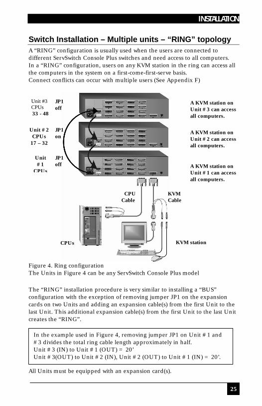
Switch Installation – Multiple units – “RING” topology A “RING” configuration is usually used when the users are connected to different ServSwitch Console Plus switches and need access to all computers. In a “RING” configuration, users on any KVM station in the ring can access all the computers in the system on a first-come-first-serve basis. Connect conflicts can occur with multiple users (See Appendix F)
Figure 4. Ring configuration The Units in Figure 4 can be any ServSwitch Console Plus model The “RING” installation procedure is very similar to installing a “BUS” configuration with the exception of removing jumper JP1 on the expansion cards on two Units and adding an expansion cable(s) from the first Unit to the last Unit. This additional expansion cable(s) from the first Unit to the last Unit creates the “RING”. All Units must be equipped with an expansion card(s).
A KVM station on Unit #3 can access all computers.
A KVM station on Unit #2 can access all computers.
A KVM station on Unit #1 can access all computers.
JP1 off
JP1 on
JP1 off
Unit #3 CPUs 33 - 48
Unit #2 CPUs
17 – 32
Unit #1
CPUs
KVM station
CPU Cable
KVM Cable
In the example used in Figure 4, removing jumper JP1 on Unit #1 and #3 divides the total ring cable length approximately in half. Unit #3 (IN) to Unit #1 (OUT) = 20’ Unit #3(OUT) to Unit #2 (IN), Unit #2 (OUT) to Unit #1 (IN) = 20’.
CPUs

SERVSWITCH™ CONSOLE PLUS
26
To begin setting up your system in a “RING” configuration, perform steps 1 – 13 as outlined in setting up a “BUS” configuration. When doing this, keep in mind that the “OUT” expansion card connector on the first Unit will be connected with an expansion cable to the “IN” expansion card connector on the last Unit to complete the “Ring”. Jumper JP1 must be removed from the lower expansion cards on two Units in the system to properly maintain cable termination. To identify which Units must have jumper JP1 removed, calculate the total cable length around the “RING”. This is from Unit #1’s “IN” connector, around the “RING” and back to Unit #1’s “OUT” connector. Jumper JP1 should be removed on Unit #1 and another switch that will divide the “RING” into approximately equal cable length distances. (See Figure 4 for a typical example) Steps: (Perform steps 1-13 described in the “BUS” installation first, page 14) (NOTE: Disconnect all cables before removing any expansion card) 1. Remove power from all ServSwitch Console Plus switches. 2. Connect an expansion cable from Unit #1’s “OUT” connector to the last
Units “IN” connector to complete the “Ring”. 3. Remove the bottom expansion card on Unit #1 and the other switch that
divide the “RING” into equal distances and remove jumper JP1 (See Figure 1), then replace the expansion cards, cables, and apply power to the two ServSwitch Console Plus switches that jumper JP1 was removed. All other ServSwitch Console Plus switches should have power off at this time.
4. Make sure a KVM station is connected to ServSwitch Console Plus #1. 5. Turn on the KVM stations video monitor and apply power to the
remaining ServSwitch Console Plus switches. (Wait for the internal diagnostic check to complete and fade out).
6. Switch the KVM station to CPU port #1 on Unit #1 by pressing and releasing the left control [Ctrl] key, type in “1” and press [Enter].
7. Pre-configure the CPU port, if needed, as outlined in steps 4a-e on page 12 if the computer being connected does not use a PC2 type keyboard or PS/2 mouse (defaults). Pre-configure the CPU port before connecting the computer. If the computer uses a PC2 type keyboard and PS/2 mouse, connect it to the corresponding CPU port. No pre-configuration is needed.
8. Boot the computer if power is not applied. You should see the boot up sequence on the KVM monitor. If the computer was connected to a pre-configured CPU port with power applied, you should see that computers video.
9. Verify that the keyboard, video, and mouse on the connected computer function properly before proceeding.

INSTALLATION
27
10. Switch the KVM station to the next sequential CPU port as explained in
step 6 and perform steps 7 – 9 for this computer and for the remaining computers.
11. Connect other KVM stations as needed to the ServSwitch Console Plus switch and verify they operate properly. (See appendix F)
This completes the basic installation of a “RING” configuration. A KVM station connected to any ServSwitch Console Plus switch can connect to any computer in the “RING”. Other configuration parameters can be set-up for the system, computers, KVM stations, users, profiles, groups, and languages. See the “Configuration menu” section for instructions on setting up these items. These installation steps are a guideline for installing multiple switches in a “RING” topology. Following these steps verify, that through the installation process, everything functions properly. Please refer to the Operations section for using the ServSwitch Console Plus switch.
SERVSWITCH™ CONSOLE PLUS
28
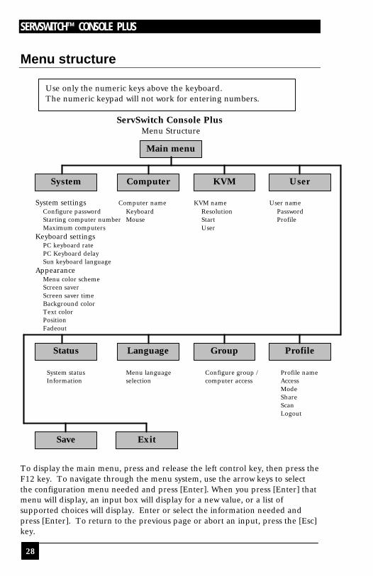
Menu structure
ServSwitch Console Plus
Menu Structure
System settings Computer name KVM name User name Configure password Keyboard Resolution Password Starting computer number Mouse Start Profile Maximum computers User
Keyboard settings PC keyboard rate PC Keyboard delay Sun keyboard language
Appearance Menu color scheme Screen saver Screen saver time Background color Text color Position Fadeout System status Menu language Configure group / Profile name Information selection computer access Access Mode Share Scan Logout
To display the main menu, press and release the left control key, then press the F12 key. To navigate through the menu system, use the arrow keys to select the configuration menu needed and press [Enter]. When you press [Enter] that menu will display, an input box will display for a new value, or a list of supported choices will display. Enter or select the information needed and press [Enter]. To return to the previous page or abort an input, press the [Esc] key.
Main menu
System Computer KVM User
Status Language Group Profile
Save Exit
Use only the numeric keys above the keyboard. The numeric keypad will not work for entering numbers.
OPERATION
29
Main Menu
Use up/down arrow keys to choose selection then press the Enter key or the Escape key to exit Configure password,box number,keyboards settings,appearance
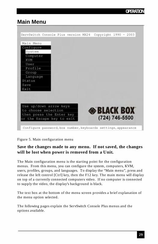
Figure 5. Main configuration menu
Save the changes made to any menu. If not saved, the changes will be lost when power is removed from a Unit. The Main configuration menu is the starting point for the configuration menus. From this menu, you can configure the system, computers, KVM, users, profiles, groups, and languages. To display the “Main menu”, press and release the left control [Ctrl] key, then the F12 key. The main menu will display on top of a currently connected computers video. If no computer is connected to supply the video, the display’s background is black. The text box at the bottom of the menu screen provides a brief explanation of the menu option selected. The following pages explain the ServSwitch Console Plus menus and the options available.
ServSwitch Console Plus version MX24 Copyright 1990 - 2003 Main Menu Configure System Computer KVM User Profile Group Language Status Save Exit
SERVSWITCH™ CONSOLE PLUS
30
Configure System menu
Configure system
System settings Configure password ******** Starting computer number 1 Maximum computers 64 Keyboard settings PC keyboard rate (chars/sec) 20 PC keyboard delay Fast Sun keyboard language US Appearance Menu color scheme Night sky Screen saver Weaving Screen saver time (seconds) 1800 Background color Cyan Text color Black Position X = 25 Y = 45 Fadeout (seconds) 5 Password to configure unit
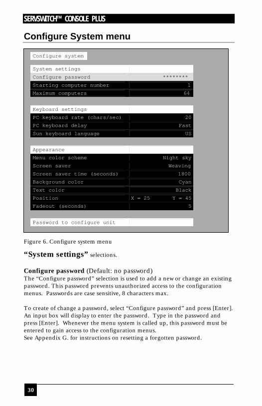
Figure 6. Configure system menu
“System settings” selections. Configure password (Default: no password) The “Configure password” selection is used to add a new or change an existing password. This password prevents unauthorized access to the configuration menus. Passwords are case sensitive, 8 characters max. To create of change a password, select “Configure password” and press [Enter]. An input box will display to enter the password. Type in the password and press [Enter]. Whenever the menu system is called up, this password must be entered to gain access to the configuration menus. See Appendix G. for instructions on resetting a forgotten password.

OPERATION
31
Starting computer number (Default: 1) The “Starting computer number” defines to the system, the first CPU port number for a particular ServSwitch Console Plus switch that is configured in an expanded topology. (See page 15) Switch #1’s starting computer number is always 1. Switch #2’s number is the total CPU ports on Unit #1 plus 1. Switch #3’s number is the total CPU ports on Unit #1 and Unit #2 plus 1, and so forth. To enter the “Starting computer” number use the up/down arrow keys and select “Starting computer number” and press [Enter]. An input box will display for a new starting computer number. Enter the new “Starting computer” number and press [Enter]. Maximum computers (Default: 64) The “Maximum computers” value is calculated by counting the number of CPU ports on all switches. This value must be entered from KVM station #1 before all Units are connected in an expansion topology. When saved, this value is propagated to all connected Units. To enter the “Maximum computers” value, select it and press [Enter]. An input box will display to enter the maximum computers value. Type in the new value and press [Enter]. “Keyboard settings” selections. PC keyboard rate (chars/sec) (Default: 20) This option adjusts the KVM keyboard action when you hold down a key to repeat a single character. Valid inputs are 1-31. PC keyboard delay (Default: Fast) This option adjusts the delay between when a key is pressed and held and when it begins to send repeated characters to the selected computer. The options are: n Slow n Medium n Fast n Fastest
SERVSWITCH™ CONSOLE PLUS
32
Sun keyboard language (Default: US) Determines the response to a Sun computer’s query for the keyboard language type used. To change the Sun keyboard language type, select it and press [Enter]. A selection box will display showing the supported Sun language choices. Use the up/down arrow keys to select the desired language and press [Enter]. The Sun keyboard language choices are: n US n US-Unix n Francais n Dansk n Deutsch n Italiano n Nederlands n Norsk n Portugues
n Espanol n Svenska/Suomea n Franco-Suisse n Schw-Deutsch n United Kingdom n Hankuko n Tai-oan n Nihongo n Canadienne
“Appearance settings” selections. Menu color scheme (Default: Night sky) Sets the colors for the configuration menus. To change the color scheme, select “Menu color scheme” and press [Enter]. A selection box will display showing the supported color schemes. Use the up/down arrow keys to select the desired scheme and press [Enter]. The menu color schemes choices are: n Night Sky – cyan, magenta, white, and blue n Tuxedo – black, red, and white n Aquarium – yellow, magenta, blue, cyan, and white n Forest – green, black, cyan, and blue Screen saver (Default: Weaving) A screen saver reduces monitor burn-in and adds an additional level of security. The screen saver automatically activates when there is no keyboard or mouse activity for an adjustable period. To change the screen saver type, select it from the menu and press [Enter]. A selection box will display showing the supported screen saver choices. Use the up/down arrow keys to select the desired screen saver and press [Enter]. The screen saver choices are: n Black screen n Fireflies n Weaving n Bounce Screen saver time (seconds) (Default: 1800 seconds) Determines the period of keyboard or mouse inactivity before activating the screen saver. To change the screen saver time, select it from the menu and press [Enter]. An input box will display to enter a new screen saver time. Enter a new value from 0 to 9999 seconds and press [Enter]. Entering a value of 0 (zero) disables the screen saver.

OPERATION
33
Background / Text color (Default: Cyan / Black) This option sets the background or text colors for the connection status and computer select screens. Colors can be one of eight solid or transparent colors. To change the background or text color, select it from the menu and press [Enter]. The color selections will display showing the solid and transparent color choices. Use the arrow keys to select the desired color and press [Enter]. The color choices are: n Black n Red n Green n Yellow n Blue n Magenta n Cyan n White (Solid or transparent) NOTE: Do not set the background and text colors the same. Position (Default: x = 25, y = 45) This option adjusts the screen position of the connection status box. Once set, this position is maintained at all video resolutions. To change the connection status box position, select it from the menu and press [Enter]. Use the arrow keys to position the status box anywhere on the screen and press [Enter] when the desired position is reached. Do not set the screen position off the visible screen area. This could cause rainbows or bars of shaded video. Valid position ranges are: Horizontal: 0 – 64, Vertical: 0 – 99 Fadeout (seconds) (Default: 5 seconds) Sets the amount of time the connection status box displays. Valid fadeout times are 0 – 255 seconds. A value of zero disables displaying the connection status box; a value of 255 will cause the connection status box to always be displayed. If the connection status box does not display when switching to a computer, increase the fadeout time. Some monitors will not display the connection status box if the fadeout time is less than the time it takes the monitor to sync to a new video signal. To change the fadeout time, select it from the menu and press [Enter]. Enter a valid new time in seconds and press [Enter].
SERVSWITCH™ CONSOLE PLUS
34
Configure Computer menu
Configure computer Computer name Keyboard Mouse
1 Computer 1 PC2 PS/2 2 Computer 2 PC2 PS/2 3 Computer 3 PC2 PS/2 4 Computer 4 PC2 PS/2 5 Computer 5 PC2 PS/2 6 Computer 6 PC2 PS/2 7 Computer 7 PC2 PS/2 8 Computer 8 PC2 PS/2 9 Computer 9 PC2 PS/2 10 Computer 10 PC2 PS/2 11 Computer 11 PC2 PS/2 12 Computer 12 PC2 PS/2 13 Computer 13 PC2 PS/2 14 Computer 14 PC2 PS/2 15 Computer 15 PC2 PS/2 16 Computer 16 PC2 PS/2
Use page up and page down keys to configure more computers Name of computer, up to 16 characters
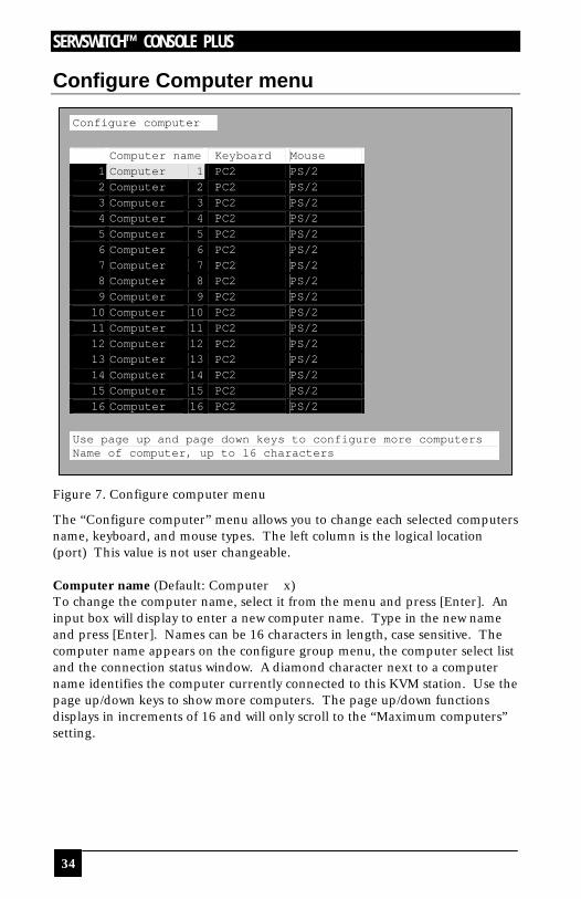
Figure 7. Configure computer menu
The “Configure computer” menu allows you to change each selected computers name, keyboard, and mouse types. The left column is the logical location (port) This value is not user changeable. Computer name (Default: Computer x) To change the computer name, select it from the menu and press [Enter]. An input box will display to enter a new computer name. Type in the new name and press [Enter]. Names can be 16 characters in length, case sensitive. The computer name appears on the configure group menu, the computer select list and the connection status window. A diamond character next to a computer name identifies the computer currently connected to this KVM station. Use the page up/down keys to show more computers. The page up/down functions displays in increments of 16 and will only scroll to the “Maximum computers” setting.

OPERATION
35
Keyboard (Default: PC mode 2) To change the keyboard type for a selected computer or configure the CPU port for a serial device, use the up/down arrow keys to select the computer whose keyboard needs changing. Use the right arrow key to select the keyboard field and press [Enter]. A selection box will display listing the supported keyboard types and serial support options. Use the up/down arrow keys to select the keyboard type or serial support needed for the selected computer and press [Enter]. The choices are: n PC1: Supports most IBM compatible PCs, PS/2 models, and PCs that do
not use PC mode 2. n PC2: Supports most PCs. n PC3: Supports Unix workstations and servers, IBM RS/6000, SGI, HP700
or 9000 series, DEC Alpha®, or other computers. n USB-PC: USB PC keyboard support. n USB-Sun: USB Sun keyboard support. n Sun: Supports Sun systems n Serial 9600,N,8,1: Serial support @ 9600 Baud rate n Serial 4800,N,8,1: Serial support @ 4800 Baud rate n Serial 2400,N,8,1: Serial support @ 2400 Baud rate n Serial 1200,N,8,1: Serial support @ 1200 Baud rate n Serial 600,N,8,1: Serial support @ 600 Baud rate n Serial 300,N,8,1: Serial support @ 300 Baud rate n Serial 110,N,8,1: Serial support @ 110 Baud rate n Serial 50,N,8,1: Serial support @ 50 Baud rate
Mouse (Default: PS/2) To change the mouse type for a selected computer, use the up/down arrow keys to select the computer whose mouse needs changing. Use the right arrow keys to select the mouse field and press [Enter]. A selection box will display listing the supported mouse types. Use the up/down arrow keys to select the correct mouse type for the selected computer and press [Enter]. The supported mouse types are: n PS/2 - 6-pin mini-Din connector with 2 or 3 buttons n PS/2 wheel - incorporates a small wheel for special functions. n Serial 2-button - connects to a computer’s COM port. n Serial 3-button - connects to a computer’s COM port. Note: If you set the mouse to PS/2 and the CPUs operating system is capable of supporting a wheel mouse, the mouse type will automatically be changed to PS/2 wheel.
SERVSWITCH™ CONSOLE PLUS
36
Configure KVM menu
Configure KVM ID BUS KVM name Resolution Start User 1 1 KVM station 1 640x480@60 0 User 1
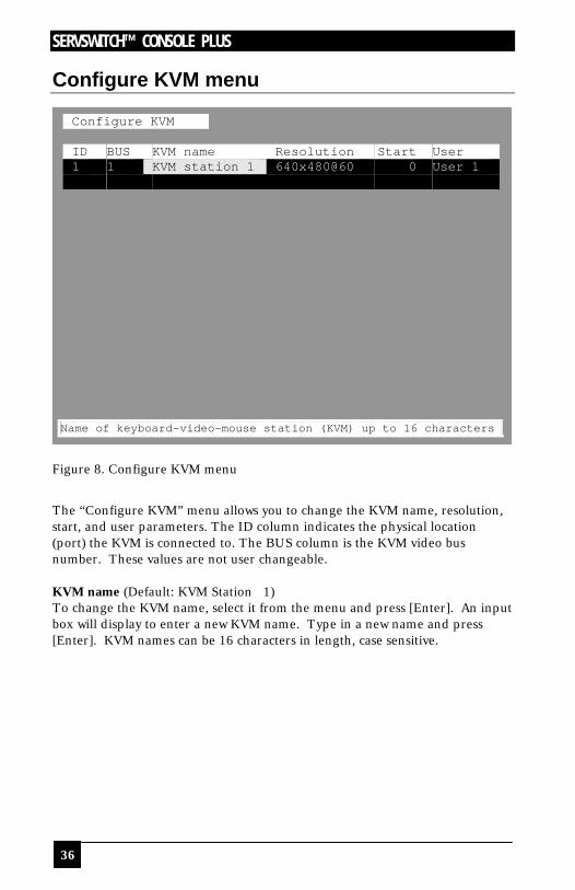
Figure 8. Configure KVM menu
The “Configure KVM” menu allows you to change the KVM name, resolution, start, and user parameters. The ID column indicates the physical location (port) the KVM is connected to. The BUS column is the KVM video bus number. These values are not user changeable. KVM name (Default: KVM Station 1) To change the KVM name, select it from the menu and press [Enter]. An input box will display to enter a new KVM name. Type in a new name and press [Enter]. KVM names can be 16 characters in length, case sensitive.
Name of keyboard-video-mouse station (KVM) up to 16 characters
OPERATION
37
Resolution (Default: 640x480@60Hz) Selects the resolution and scan rate of the on-screen display when no attached computer video is present. If a computer video is shown, the detected video resolution from the connected computer is used. To change the resolution for a selected KVM station, select the KVM station to change the resolution and using the left arrow key, select the resolution field and press [Enter]. A list of supported resolutions will display. Select the new resolution from the list and press [Enter]. The supported resolutions are: n 640 x 480 @ 60Hz n 640 x 480 @ 72Hz n 640 x 480 @ 75Hz n 640 x 480 @ 67Hz n 832 x 624 @ 75Hz n 1152 x 900 @ 66Hz n 1152 x 900 @ 76Hz Start (Default: 0) Assigns the CPU port number the KVM station will connect to on start up and login. 0 = no connection. To change the value, select it from the menu and press [Enter]. Type in the CPU port number the selected KVM station will connect to upon start up or login and press [Enter]. User (Default: User 1) This field is used to assign a specific user to a KVM station. To change the user, first select the KVM station, then select the user field and press [Enter]. A selection box will display a list of user names followed by “Login”. Select the user to assign to the selected KVM station and press [Enter]. Use the page up/down keys to display more users. If “Login” is selected, the KVM user must login with their user ID and assigned password to gain access to the KVM station. The configure user, profile, and group menus all tie together to provide access control to the computers. A group defines which computers in the system can and cannot be accessed. This group is assigned to a profile name. The profile defines how the computers (defined by the group) can be accessed. The profile is assigned to a user or users. When a user logs on to a KVM station, their assigned profile is validated. This profile defines which group has been assigned (which computers can be accessed), what mode the user can connect to the computers with (view, share, control, private), the share time, scan time, and logout time.
SERVSWITCH™ CONSOLE PLUS
38
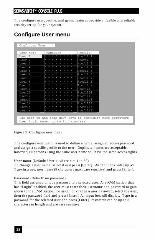
The configure user, profile, and group features provide a flexible and reliable security set-up for your system.
Configure User menu
Configure User User name Password Profile User 1 * * * * * * * * Profil 1 User 2 * * * * * * * * Profil 2 User 3 * * * * * * * * Profil 3 User 4 * * * * * * * * Profil 4 User 5 * * * * * * * * Profil 5 User 6 * * * * * * * * Profil 6 User 7 * * * * * * * * Profil 7 User 8 * * * * * * * * Profil 8 User 9 * * * * * * * * Profil 9 User10 * * * * * * * * Profil10 User11 * * * * * * * * Profil11 User12 * * * * * * * * Profil12 User13 * * * * * * * * Profil13 User14 * * * * * * * * Profil14 User15 * * * * * * * * Profil15 User16 * * * * * * * * Profil16 Use page up and page down keys to configure more computers User login name, up to 8 characters
Figure 9. Configure user menu
The configure user menu is used to define a name, assign an access password, and assign a specific profile to the user. Duplicate names are acceptable, however, all persons using the same user name will have the same access rights. User name (Default: User x, where x = 1 to 80) To change a user name, select it and press [Enter]. An input box will display. Type in a new user name (8 characters max. case sensitive) and press [Enter]. Password (Default: no password) This field assigns a unique password to a selected user. Any KVM station that has “Login” enabled, the user must enter their username and password to gain access to the KVM station. To assign or change a user password, select the user, then the password field and press [Enter]. An input box will display. Type in a password for the selected user and press [Enter]. Passwords can be up to 8 characters in length and are case sensitive.
OPERATION
39
Profile (Default: Profile x, where x = 1 to 80) This field is used to assign an access profile to a selected user. Profiles can be defined to limit the type of access to the computers. To change an assigned profile for a selected user, first select the user, then select the profile to change and press [Enter]. A selection box will display listing the profiles available. Select the profile to assign to the selected user and press [Enter]. Use the page up/down keys for more profiles. Profiles are defined on the “Configure profile” menu.

SERVSWITCH™ CONSOLE PLUS
40
Configure Profile menu
Configure Profile Name Access Mode Share Scan Logout Profil 1 Group 1 Share 2 5 240 Profil 2 Group 2 Share 2 5 240 Profil 3 Group 3 Share 2 5 240 Profil 4 Group 4 Share 2 5 240 Profil 5 Group 5 Share 2 5 240 Profil 6 Group 6 Share 2 5 240 Profil 7 Group 7 Share 2 5 240 Profil 8 Group 8 Share 2 5 240 Profil 9 Group 9 Share 2 5 240 Profil10 Group10 Share 2 5 240 Profil11 Group11 Share 2 5 240 Profil12 Group12 Share 2 5 240 Profil13 Group13 Share 2 5 240 Profil14 Group14 Share 2 5 240 Profil15 Group15 Share 2 5 240 Profil16 Group16 Share 2 5 240 Use page up and page down keys to configure more profiles Profile name, up to 8 characters
Figure 10. Configure profile menu
The configure profile menu is used to assign computer access levels, modes, share, scan and logout times. Name (Default: Profil x, where x = 1 to 80) The profile name can be changed to any name up to 8 characters in length. The name can be a specific user, a group of users within a department, a business department, or any name that defines the profile. To change the profile name, select the one to change and press [Enter]. An input box will display. Type in a new profile name and press [Enter]. Access (Default: Group x, where x = 1 to 80) This field is used to assign each profile to a group. To change the access for a selected profile, select the profile to change then select the group to change and press [Enter]. A list of groups will display. Select the group that has been set-up for the selected profile and press [Enter]. A group is set up on the configure group menu.
OPERATION
41
Mode (Default: Share) Assigns 1 of 4 modes to a profile. To change the mode, select the profile to change the mode, then select the mode to change and press [Enter]. A selection box will display. Select the mode needed and press [Enter]. The modes are: n View – Profiles set to the view mode allow users to switch to any computer,
but have no keyboard or mouse control, only view privileges. n Share – Profiles set to the share mode allow users to take keyboard and
mouse control of a computer on a first come, first serve basis. Control of the computer is based on the time-out value entered in the share column.
n Control – Profiles set to the control mode allow users to take exclusive control of a computer. No time-out value is invoked. Other users that try to connect to the same computer can only view the video. They have no keyboard or mouse control until the user with the control disconnects from the computer.
n Private – This mode is the same as the control mode except other users cannot view the video or access the computer.
Share (Default: 2 seconds) This feature allows other users to take keyboard and mouse control of a computer after a specific time of no keyboard or mouse activity by a user. To change the Share time for a given profile, select the profile, then the Share to change and press [Enter]. An input box will display. Type in a new share value in seconds and press [Enter]. Valid share values are 0 to 9999 seconds. The share value is only valid if the profile mode is share. (See Appendix F.) Scan (Default: 5 seconds) When a user invokes the scan function, this feature sets the time the video is displayed before switching to the next sequential computers video. To change the scan rate, select the profile, then the scan rate to change and press [Enter]. An input box will display. Type in a new scan time and press [Enter]. Valid scan times are 0 to 9999. If the video is not present during the scan mode, the scan value may be set to low and the monitor cannot synchronize to the video fast enough to display it. This usually happens with a scan value of 4 or lower. If this problem occurs, increase the scan value. 0 (zero) is a valid entry but not recommended. Logout (Default: 240 minutes) This setting disconnects and logs out a user after the set period of no keyboard or mouse activity. To change the logout value, select the profile, then the logout time to change and press [Enter]. An input box will display. Type in a new logout time and press [Enter]. Valid times are 0 to 9999 minutes. A value of 0 (zero) disables the automatic logout function. If login is enabled for a KVM station, but the Logout time is set to zero, the user remains logged in until they manually log out using the [Ctrl] L command. (See Table 1, keyboard commands)
SERVSWITCH™ CONSOLE PLUS
42
Configure Group menu
Configure Group Computer Group 1 1 Computer 1 + + + + + + + + + + + + + + + + + 2 Computer 2 + + + + + + + + + + + + + + + + + 3 Computer 3 + + + + + + + + + + + + + + + + + 4 Computer 4 + + + + + + + + + + + + + + + + + 5 Computer 5 + + + + + + + + + + + + + + + + + 6 Computer 6 + + + + + + + + + + + + + + + + + 7 Computer 7 + + + + + + + + + + + + + + + + + 8 Computer 8 + + + + + + + + + + + + + + + + + 9 Computer 9 + + + + + + + + + + + + + + + + + 10 Computer 10 + + + + + + + + + + + + + + + + + 11 Computer 11 + + + + + + + + + + + + + + + + + 12 Computer 12 + + + + + + + + + + + + + + + + + 13 Computer 13 + + + + + + + + + + + + + + + + + 14 Computer 14 + + + + + + + + + + + + + + + + + 15 Computer 15 + + + + + + + + + + + + + + + + + 16 Computer 16 + + + + + + + + + + + + + + + + +
SPACE BAR adds/removes computer from group Enter renames group Page up/down more computers + computer belongs to group
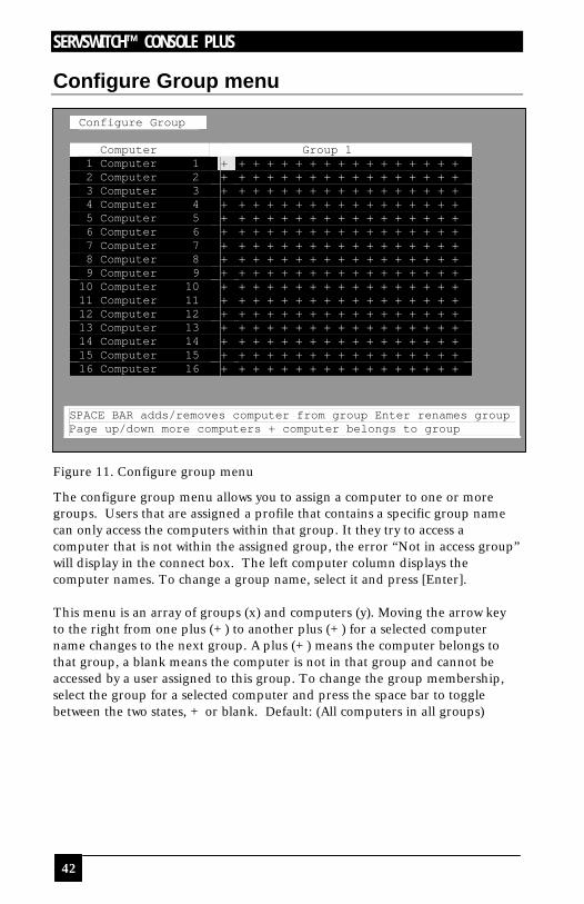
Figure 11. Configure group menu
The configure group menu allows you to assign a computer to one or more groups. Users that are assigned a profile that contains a specific group name can only access the computers within that group. It they try to access a computer that is not within the assigned group, the error “Not in access group” will display in the connect box. The left computer column displays the computer names. To change a group name, select it and press [Enter]. This menu is an array of groups (x) and computers (y). Moving the arrow key to the right from one plus (+) to another plus (+) for a selected computer name changes to the next group. A plus (+) means the computer belongs to that group, a blank means the computer is not in that group and cannot be accessed by a user assigned to this group. To change the group membership, select the group for a selected computer and press the space bar to toggle between the two states, + or blank. Default: (All computers in all groups)
OPERATION
43
Configure Language menu
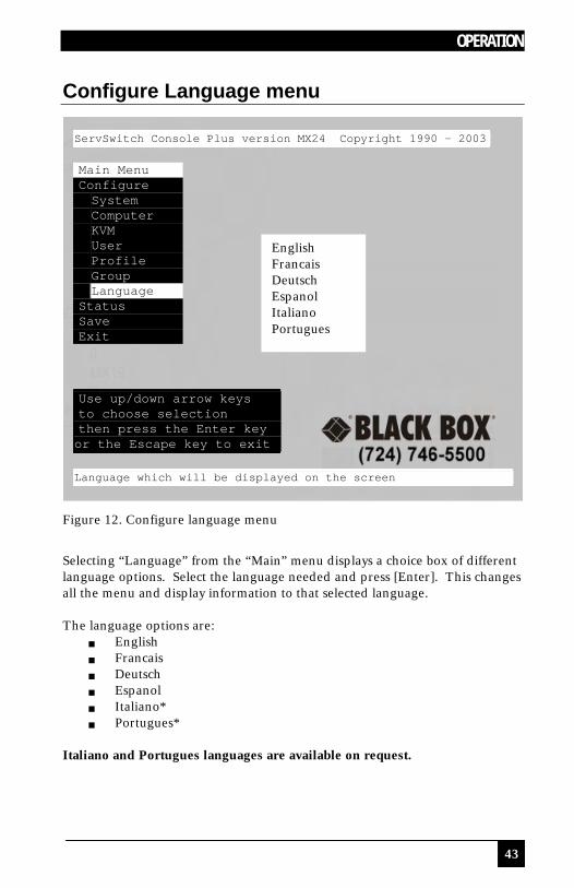
Figure 12. Configure language menu
Selecting “Language” from the “Main” menu displays a choice box of different language options. Select the language needed and press [Enter]. This changes all the menu and display information to that selected language. The language options are:
g English g Francais g Deutsch g Espanol g Italiano* g Portugues*
Italiano and Portugues languages are available on request.
ServSwitch Console Plus version MX24 Copyright 1990 - 2003 Main Menu Configure System Computer KVM User Profile Group Language Status Save Exit Use up/down arrow keys to choose selection then press the Enter key or the Escape key to exit Language which will be displayed on the screen
English Francais Deutsch Espanol Italiano Portugues
SERVSWITCH™ CONSOLE PLUS
44
System Status display
System Status Computers Power Pos Ver KVM CPU User Status
1-4 1 24 PC 1 User 1 Share mode 5-8 2 24 PC Share mode 9-12 3 24 PC Share mode 13-16 4 24 PC Share mode 17-20 1 24 PC No response 21-24 2 24 PC No response 25-28 3 24 PC No response 29-32 4 24 PC No response 33-36 1 24 PC No response 37-40 2 24 PC No response 41-44 3 24 PC No response 45-48 4 24 PC No response 49-52 1 24 PC No response 53-56 2 24 PC No response 57-60 3 24 PC No response 61-64 4 24 PC No response
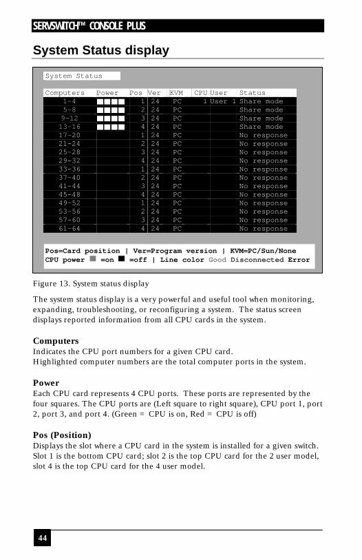
Figure 13. System status display
The system status display is a very powerful and useful tool when monitoring, expanding, troubleshooting, or reconfiguring a system. The status screen displays reported information from all CPU cards in the system. Computers Indicates the CPU port numbers for a given CPU card. Highlighted computer numbers are the total computer ports in the system. Power Each CPU card represents 4 CPU ports. These ports are represented by the four squares. The CPU ports are (Left square to right square), CPU port 1, port 2, port 3, and port 4. (Green = CPU is on, Red = CPU is off) Pos (Position) Displays the slot where a CPU card in the system is installed for a given switch. Slot 1 is the bottom CPU card; slot 2 is the top CPU card for the 2 user model, slot 4 is the top CPU card for the 4 user model.
Pos=Card position | Ver=Program version | KVM=PC/Sun/None CPU power =on =off | Line color Good Disconnected Error

OPERATION
45
Ver (Version) Displays the last three digits of the firmware main program version for the CPU card. KVM Indicates the type of keyboard and mouse detected if a KVM station is attached to this CPU card. CPU Displays the computer number currently selected by the KVM station. User Displays the users name that is currently accessing the system. Status Displays the most recent connect or disconnect status for the KVM station on this CPU card.

SERVSWITCH™ CONSOLE PLUS
46
Save menu ServSwitch Console Plus version MX24 Copyright 1990-2003 Main Menu Configure System Computer KVM User Profile Group Language Status Save Exit
Use up/down arrow keys to choose selection then press the Enter key or the Escape key to exit Configure password,box number,keyboards settings,appearance
Figure 14. Save menu
When changes are made to any configuration, they must be saved in flash memory to insure that the changes will be active after a power cycle. It is recommended that all users be logged off from all systems prior to saving any configuration changes. To save the settings, select save and press [Enter]. The unit will check and display how many CPU cards in the system to update. This is the total number of CPU cards (RS232 ports) in the system not counting the one the KVM station is connected to. (Total boards – 1) A YES/NO selection box will display. Choose “YES” to save the changes to flash memory on all powered-on units. Choose “NO” for temporary or incorrect changes. The temporary settings will only be in effect as long as power is applied to the Unit. Once power is cycled, unsaved changes, other than the starting computer number, are lost and the previously saved configuration settings will be effective.
Boards to update =
Save configuration?
YES
NO
OPERATION
47
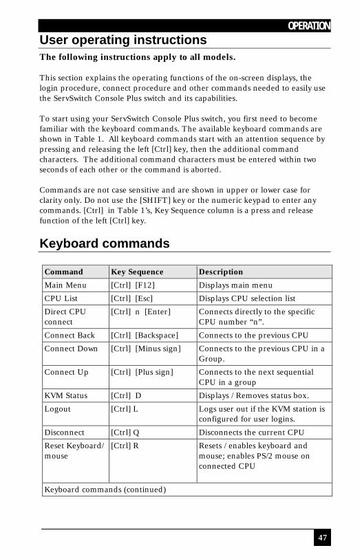
User operating instructions The following instructions apply to all models. This section explains the operating functions of the on-screen displays, the login procedure, connect procedure and other commands needed to easily use the ServSwitch Console Plus switch and its capabilities. To start using your ServSwitch Console Plus switch, you first need to become familiar with the keyboard commands. The available keyboard commands are shown in Table 1. All keyboard commands start with an attention sequence by pressing and releasing the left [Ctrl] key, then the additional command characters. The additional command characters must be entered within two seconds of each other or the command is aborted. Commands are not case sensitive and are shown in upper or lower case for clarity only. Do not use the [SHIFT] key or the numeric keypad to enter any commands. [Ctrl] in Table 1’s, Key Sequence column is a press and release function of the left [Ctrl] key.
Keyboard commands
Command Key Sequence Description
Main Menu [Ctrl] [F12] Displays main menu
CPU List [Ctrl] [Esc] Displays CPU selection list
Direct CPU connect
[Ctrl] n [Enter] Connects directly to the specific CPU number “n”.
Connect Back [Ctrl] [Backspace] Connects to the previous CPU
Connect Down [Ctrl] [Minus sign] Connects to the previous CPU in a Group.
Connect Up [Ctrl] [Plus sign] Connects to the next sequential CPU in a group
KVM Status [Ctrl] D Displays / Removes status box.
Logout [Ctrl] L Logs user out if the KVM station is configured for user logins.
Disconnect [Ctrl] Q Disconnects the current CPU
Reset Keyboard/ mouse
[Ctrl] R Resets / enables keyboard and mouse; enables PS/2 mouse on connected CPU
Keyboard commands (continued)

SERVSWITCH™ CONSOLE PLUS
48
Command Key Sequence Description
Send Null Byte [Ctrl] N Sends a null byte to the CPU’s PS/2 mouse port. Use this command if the PS/2 mouse gets “out of sync”.
Reset Mouse (NT or Unix systems only)
[Ctrl] O (not zero) Resets the currently selected NT or Unix computers PS/2 mouse. Also switches the NT mouse driver to “wheel” mode.
Start Scan [Ctrl] S Sequentially steps through all connected CPUs in a group.
Stop Scan [Ctrl] X Turns scan “Off”
Table 1. Keyboard commands
When you first start using a KVM station, it may require you to login. If the KVM station requires a login, the login box, shown in Figure 15, will display. The login box appears when a Unit is powered on, when a user logs off, or when a preset time interval passes with no keyboard or mouse activity. If a login is required, type in your User ID and press [Enter]. (User ID is the user name defined on the configure user menu) If the user ID is validated, you can then type in your password and press [Enter]. If the password is validated, the KVM station can be accessed. A user may login with the same user ID and password at more than one KVM station. Both the User ID and password are case sensitive.
Figure 15. Login screen
Once you have access to a KVM station, you can switch to any of the connected computers provided your security profile allows access to that computer. To connect to a computer, you can use the “Direct CPU Connect” keyboard command or the “Computer select” menu. (See Table 1) To access the “Computer select” menu, press and release the left [Ctrl] key, then press the [Esc] key. The computer select menu shown in Figure 16 will display. Use the up/down arrow keys and the page up/page down keys and select the computer to switch to and press [Enter]. You will be immediately connected to that computer and a connection status messages will display providing information about the connection between the KVM station and the computer. Pressing the F1 key will sort the list, F2 key will display the status screen.
Login Control Room
User ID Password

OPERATION
49
Figure 16. Computer select menu
Figures 16, 17, and 18 show an example of the connection status messages that are displayed when connecting to a computer.
Figure 17. Connection successful message
Computer select menu
1 Mail server 2 NT Server 1 3 NT server 2 4 NT server 3 5 Inventory 1 6 Inventory 2 7 Sales 8 Marketing 9 Engineering 10 Computer 10 11 Computer 11 12 Computer 12 13 Computer 13 14 Computer 14 15 Computer 15 16 Computer 16 F1 – Sort F2 – Status #
Status Mail server
Connection successful to NT Server On Admin Share mode
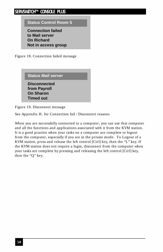
SERVSWITCH™ CONSOLE PLUS
50
Figure 18. Connection failed message
Figure 19. Disconnect message
See Appendix H. for Connection fail / Disconnect reasons When you are successfully connected to a computer, you can use that computer and all the functions and applications associated with it from the KVM station. It is a good practice when your tasks on a computer are complete to logout from the computer, especially if you are in the private mode. To Logout of a KVM station, press and release the left control [Ctrl] key, then the “L” key. If the KVM station does not require a login, disconnect from the computer when your tasks are complete by pressing and releasing the left control [Ctrl] key, then the “Q” key.
Status Control Room 5
Connection failed to Mail server On Richard Not in access group
Status Mail server
Disconnected from Payroll On Sharon Timed out
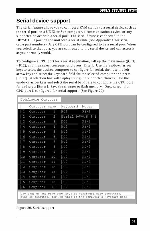
SERIAL CONTROL PORT
51
Serial device support The serial feature allows you to connect a KVM station to a serial device such as the serial port on a UNIX or Sun computer, a communication device, or any supported device with a serial port. The serial device is connected to the DB25F CPU port on the unit with a serial cable (See Appendix C for serial cable part numbers). Any CPU port can be configured to be a serial port. When you switch to that port, you are connected to the serial device and can access it as you normally would. To configure a CPU port for a serial application, call up the main menu ([Ctrl] – F12), and then select computer and press [Enter]. Use the up/down arrow keys to select the desired computer to configure for serial, then use the left arrow key and select the keyboard field for the selected computer and press [Enter]. A selection box will display listing the supported choices. Use the up/down arrow keys and select the serial baud rate to configure the CPU port for and press [Enter]. Save the changes to flash memory. Once saved, that CPU port is configured for serial support. (See Figure 20)
Configure Computer
Computer name Keyboard Mouse 1 Computer 1 PC2 PS/2 2 Computer 2 Serial 9600,N,8,1 3 Computer 3 PC2 PS/2 4 Computer 4 PC2 PS/2 5 Computer 5 PC2 PS/2 6 Computer 6 PC2 PS/2 7 Computer 7 PC2 PS/2 8 Computer 8 PC2 PS/2 9 Computer 9 PC2 PS/2 10 Computer 10 PC2 PS/2 11 Computer 11 PC2 PS/2 12 Computer 12 PC2 PS/2 13 Computer 13 PC2 PS/2 14 Computer 14 PC2 PS/2 15 Computer 15 PC2 PS/2 16 Computer 16 PC2 PS/2
Use page up and page down keys to configure more computers, type of computer, for PCs this is the computer’s keyboard mode
Figure 20. Serial support
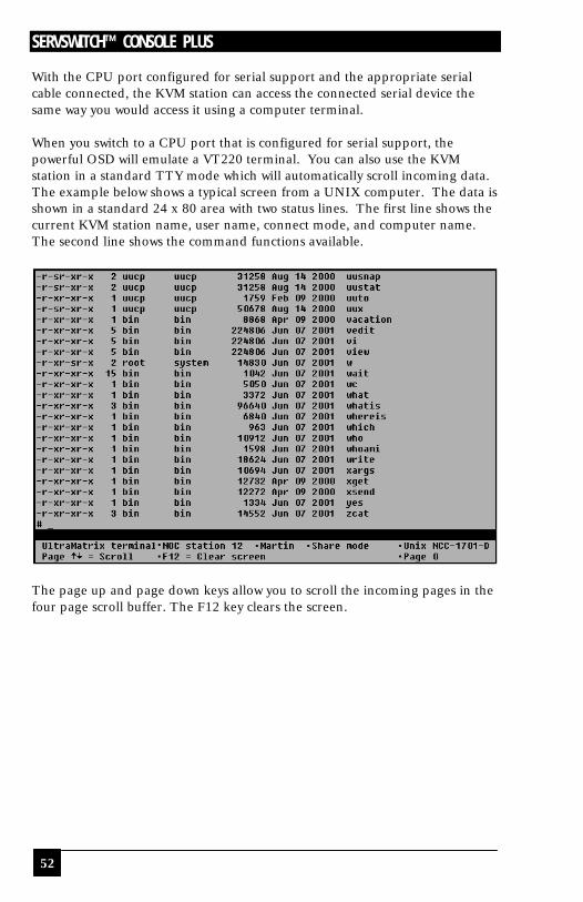
SERVSWITCH™ CONSOLE PLUS
52
With the CPU port configured for serial support and the appropriate serial cable connected, the KVM station can access the connected serial device the same way you would access it using a computer terminal. When you switch to a CPU port that is configured for serial support, the powerful OSD will emulate a VT220 terminal. You can also use the KVM station in a standard TTY mode which will automatically scroll incoming data. The example below shows a typical screen from a UNIX computer. The data is shown in a standard 24 x 80 area with two status lines. The first line shows the current KVM station name, user name, connect mode, and computer name. The second line shows the command functions available.
The page up and page down keys allow you to scroll the incoming pages in the four page scroll buffer. The F12 key clears the screen.
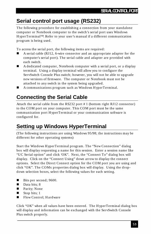
SERIAL CONTROL PORT
53
Serial control port usage (RS232) The following procedure for establishing a connection from your standalone computer or Notebook computer to the switch’s serial port uses Windows HyperTerminal™. Refer to your user’s manual if a different communication program is being used. To access the serial port, the following items are required: n A serial cable (RJ12, 6-wire connector and an appropriate adapter for the
computer's serial port). The serial cable and adapter are provided with each switch.
n A dedicated computer, Notebook computer with a serial port, or a display terminal. Using a display terminal will allow you to configure the ServSwitch Console Plus switch; however, you will not be able to upgrade new versions of firmware. The computer or Notebook must not be attached to any switch in the system being upgraded.
n A communications program such as Windows HyperTerminal.
Connecting the Serial Cable Attach the serial cable from the RS232 port #1 (bottom right RJ12 connector) to the COM port on your computer. This COM port must be the same communication port HyperTerminal or your communication software is configured for.
Setting up Windows HyperTerminal (The following instructions are using Windows 95/98; the instructions may be different for other operating systems) Start the Windows HyperTerminal program. The “New Connection” dialog box will display requesting a name for this session. Enter a session name like “UC Serial option” and click ‘OK”. Next, the “Connect To” dialog box will display. Click on the “Connect Using” down arrow to display the connect options. Select the Direct Connect option for the COM port you are using and click “OK”. The COMx properties dialog box will display. Using the drop-down selection boxes, select the following values for each setting. n Bits per second; 9600. n Data bits; 8 n Parity; None n Stop bits; 1 n Flow Control; Hardware Click “OK” when all values have been entered. The HyperTerminal dialog box will display and information can be exchanged with the ServSwitch Console Plus switch properly.

SERVSWITCH™ CONSOLE PLUS
54
You can save this setup so the next time its needed, you can select the ICON with the name you gave it and these settings will already be established.
Starting a serial communication session Verify that “Connected” appears in the bottom left corner of the HyperTerminal window. If “Connected” is not present, click on the “Call” icon. “Connected” should display in the bottom left corner. Power on or cycle power on the switch and press the spacebar when the message, “Hit the spacebar within 5 seconds to get serial options menu” appears on your screen. The serial menu will appear after the diagnostic check completes. If unrecognizable characters appear, the baud rate set on the switches serial port and the baud rate set on your computers COM port are not set to the same value. Disconnect from the ServSwitch Console Plus by clicking on the “Disconnect” ICON. Change the baud rate on your terminal or computers communication program from 9600 (set previously) to 57,600. Re-connect by clicking on the “Call” ICON. Cycle power on the unit, press the space bar, and the serial option menu will display and should be legible. The serial menu (Figure 21) enables you to perform certain configuration settings and perform flash upgrades. Following explains the serial menu options:
Figure 21. Serial menu
ServSwitch Console Plus Serial option - HyperTerminal
Serial options menu 1) Change starting computer number … 1 2) Change the serial port baud rate … 9600 3) Receive new main program or kernel from serial port (this card only) 4) Send this unit’s main program to other units 5) Send this unit’s kernel to other units 6) Reset configuration data to factory defaults (this card only) 7) Save changes made in 1 and 2 (this card only) 8) Exit (restart the unit) Enter choice - - >
File Edit View Call Transfer Help
Connected 0:03:00 Auto detect 9600 8-N-1 Scroll CAPS NUv Capture Print echo
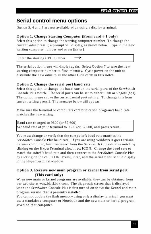
SERIAL CONTROL PORT
55
Serial control menu options Option 3, 4 and 5 are not available when using a display terminal. Option 1. Change Starting Computer (From card #1 only) Select this option to change the starting computer number. To change the current value press 1; a prompt will display, as shown below. Type in the new starting computer number and press [Enter].
The serial option menu will display again. Select Option 7 to save the new starting computer number to flash memory. Cycle power on the unit to distribute the new value to all the other CPU cards in this switch. Option 2. Change the serial port baud rate Select this option to change the baud rate on the serial ports of the ServSwitch Console Plus switch. The serial ports can be set to either 9600 or 57,600 (bps). The option menu shows the current serial port setting. To change this from current setting press 2. The message below will appear. Make sure the terminal or computers communication program’s baud rate matches the new setting. You must change or verify that the computer’s baud rate matches the ServSwitch Console Plus baud rate. If you are using Windows HyperTerminal on your computer, first disconnect from the ServSwitch Console Plus switch by clicking on the HyperTerminal disconnect ICON. Change the baud rate to match the switch’s baud rate and then connect to the ServSwitch Console Plus by clicking on the call ICON. Press [Enter] and the serial menu should display in the HyperTerminal window. Option 3. Receive new main program or kernel from serial port (This card only) When new main or kernel programs are available, they can be obtained from our web site at www.blackbox.com. The diagnostic screen that is displayed when the ServSwitch Console Plus is first turned on shows the Kernel and main program version that is presently installed. You cannot update the flash memory using only a display terminal; you must use a standalone computer or Notebook and the new main or kernel program saved on that computer.
Enter the starting CPU number
Baud rate changed to 9600 (or 57,600) Set baud rate of your terminal to 9600 (or 57.600) and press return.
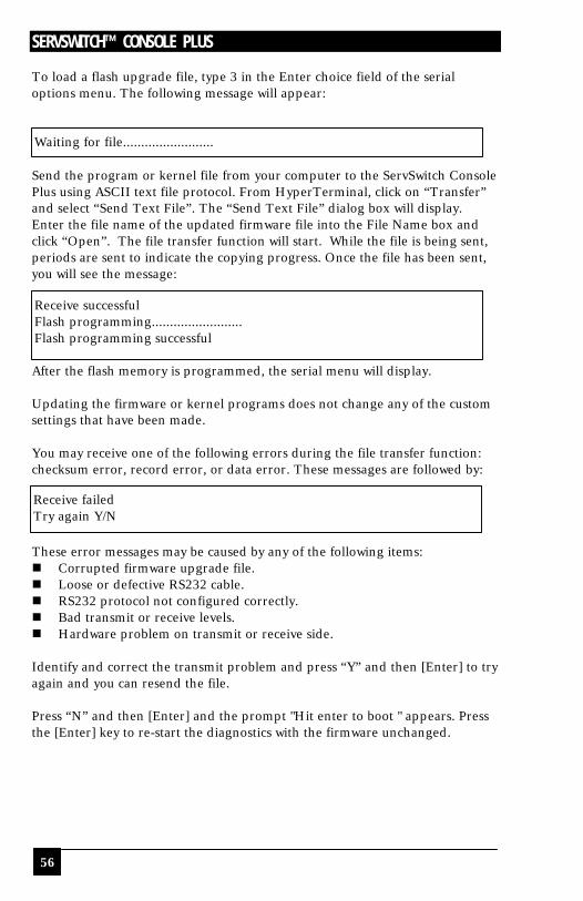
SERVSWITCH™ CONSOLE PLUS
56
To load a flash upgrade file, type 3 in the Enter choice field of the serial options menu. The following message will appear: Send the program or kernel file from your computer to the ServSwitch Console Plus using ASCII text file protocol. From HyperTerminal, click on “Transfer” and select “Send Text File”. The “Send Text File” dialog box will display. Enter the file name of the updated firmware file into the File Name box and click “Open”. The file transfer function will start. While the file is being sent, periods are sent to indicate the copying progress. Once the file has been sent, you will see the message: After the flash memory is programmed, the serial menu will display. Updating the firmware or kernel programs does not change any of the custom settings that have been made. You may receive one of the following errors during the file transfer function: checksum error, record error, or data error. These messages are followed by: These error messages may be caused by any of the following items: n Corrupted firmware upgrade file. n Loose or defective RS232 cable. n RS232 protocol not configured correctly. n Bad transmit or receive levels. n Hardware problem on transmit or receive side. Identify and correct the transmit problem and press “Y” and then [Enter] to try again and you can resend the file. Press “N” and then [Enter] and the prompt "Hit enter to boot " appears. Press the [Enter] key to re-start the diagnostics with the firmware unchanged.
Waiting for file.........................
Receive successful Flash programming......................... Flash programming successful
Receive failed Try again Y/N
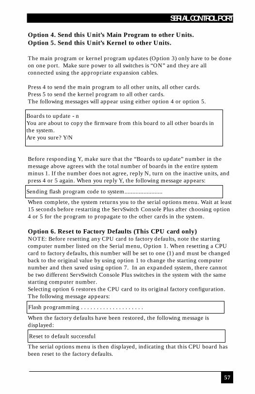
SERIAL CONTROL PORT
57
Option 4. Send this Unit’s Main Program to other Units. Option 5. Send this Unit’s Kernel to other Units. The main program or kernel program updates (Option 3) only have to be done on one port. Make sure power to all switches is “ON” and they are all connected using the appropriate expansion cables. Press 4 to send the main program to all other units, all other cards. Press 5 to send the kernel program to all other cards. The following messages will appear using either option 4 or option 5. Before responding Y, make sure that the “Boards to update” number in the message above agrees with the total number of boards in the entire system minus 1. If the number does not agree, reply N, turn on the inactive units, and press 4 or 5 again. When you reply Y, the following message appears: When complete, the system returns you to the serial options menu. Wait at least 15 seconds before restarting the ServSwitch Console Plus after choosing option 4 or 5 for the program to propagate to the other cards in the system. Option 6. Reset to Factory Defaults (This CPU card only) NOTE: Before resetting any CPU card to factory defaults, note the starting computer number listed on the Serial menu, Option 1. When resetting a CPU card to factory defaults, this number will be set to one (1) and must be changed back to the original value by using option 1 to change the starting computer number and then saved using option 7. In an expanded system, there cannot be two different ServSwitch Console Plus switches in the system with the same starting computer number. Selecting option 6 restores the CPU card to its original factory configuration. The following message appears: When the factory defaults have been restored, the following message is displayed: The serial options menu is then displayed, indicating that this CPU board has been reset to the factory defaults.
Boards to update - n You are about to copy the firmware from this board to all other boards in the system. Are you sure? Y/N
Sending flash program code to system........................
Flash programming . . . . . . . . . . . . . . . . . . . .
Reset to default successful
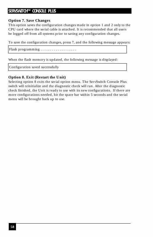
SERVSWITCH™ CONSOLE PLUS
58
Option 7. Save Changes This option saves the configuration changes made in option 1 and 2 only to the CPU card where the serial cable is attached. It is recommended that all users be logged off from all systems prior to saving any configuration changes. To save the configuration changes, press 7, and the following message appears: When the flash memory is updated, the following message is displayed: Option 8. Exit (Restart the Unit) Selecting option 8 exits the serial option menu. The ServSwitch Console Plus switch will reinitialize and the diagnostic check will run. After the diagnostic check finished, the Unit is ready to use with its new configurations. If there are more configurations needed, hit the space bar within 5 seconds and the serial menu will be brought back up to use.
Flash programming . . . . . . . . . . . . . . . . . . .
Configuration saved successfully
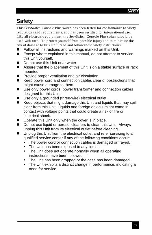
SAFETY
59
Safety This ServSwitch Console Plus switch has been tested for conformance to safety regulations and requirements, and has been certified for international use. Like all electronic equipment, the ServSwitch Console Plus switch should be used with care. To protect yourself from possible injury and to minimize the risk of damage to this Unit, read and follow these safety instructions. n Follow all instructions and warnings marked on this Unit. n Except where explained in this manual, do not attempt to service
this Unit yourself. n Do not use this Unit near water. n Assure that the placement of this Unit is on a stable surface or rack
mounted. n Provide proper ventilation and air circulation. n Keep power cord and connection cables clear of obstructions that
might cause damage to them. n Use only power cords, power transformer and connection cables
designed for this Unit. n Use only a grounded (three-wire) electrical outlet. n Keep objects that might damage this Unit and liquids that may spill,
clear from this Unit. Liquids and foreign objects might come in contact with voltage points that could create a risk of fire or electrical shock.
n Operate this Unit only when the cover is in place. n Do not use liquid or aerosol cleaners to clean this Unit. Always
unplug this Unit from its electrical outlet before cleaning. n Unplug this Unit from the electrical outlet and refer servicing to a
qualified service center if any of the following conditions occur: § The power cord or connection cables is damaged or frayed. § The Unit has been exposed to any liquids. § The Unit does not operate normally when all operating
instructions have been followed. § The Unit has been dropped or the case has been damaged. § The Unit exhibits a distinct change in performance, indicating a
need for service.
SERVSWITCH™ CONSOLE PLUS
60
Safety and EMC Regulatory Statements Safety Information
Documentation reference symbol. If the product is marked with this symbol, refer to the product documentation to get more information about the product.
WARNING A WARNING in the manual denotes a hazard that can cause injury or death.
CAUTION A CAUTION in the manual denotes a hazard that
can damage equipment.
Do not proceed beyond a WARNING or CAUTION notice until you have understood the hazardous conditions and have taken appropriate steps. Grounding These are Safety Class I products and have protective earthing terminals. There must be an un-interruptible safety earth ground from the main power source to the product’s input wiring terminals, power cord, or supplied power cord set. Whenever it is likely that the protection has been impaired, disconnect the power cord until the ground has been restored. Servicing There are no user-serviceable parts inside these products. Only service-trained personnel must perform any servicing, maintenance, or repair. The user may adjust only items mentioned in this manual.

TROUBLESHOOTING
61
Troubleshooting Computer does not boot, keyboard or mouse error received n CPU cable is loose. Re-seat cable and hit F1 to continue or reboot
computer. n Wrong cable plugged in. Keyboard and mouse cables reversed. n CPU cable is defective. Try using CPU cable from another computer. If
problem goes away, cable is defective. n Port on ServSwitch Console Plus is defective. Try using another port. If
problem goes away, port is defective. n Port on computer is defective. Try plugging in keyboard or mouse directly.
If problem remains, computer port is defective. If computer power status LED not lit, fuse on motherboard may be blown.
Mouse driver does not load n If PS/2 type mouse, computer must be attached to the ServSwitch Console
Plus or mouse at boot-up time in order for mouse to be recognized by the computer. Reboot computer with the ServSwitch Console Plus powered on and a CPU cable attached.
n Incompatible or old mouse driver being used. Update mouse driver. Can't switch computer port from keyboard n Power to the ServSwitch Console Plus was removed for less than three
seconds possibly causing keyboard to lock up. Detach and reattach keyboard.
n The mode of the keyboard does not match that of the computer. Issue the mode command, usually 1 for IBM PS/2s, and 2 for all others. The default setting of the ServSwitch Console Plus is mode 2. Sometimes an incorrect mode will confuse the computer or keyboard. This requires re-booting the computer or resetting the keyboard by unplugging and plugging it back in.
n If trying to reach a remote port, that port is busy. Try again later. n If trying to reach a remote port, the expansion cable is detached or the
remote Unit is powered off. n Keyboard port or computer port cable detached. Wrong or missing characters from those typed n The keyboard mode is incorrect; configure computer port for correct
keyboard mode. Can't access all functions of mouse n If Microsoft BallPoint mouse, get latest Microsoft mouse driver.
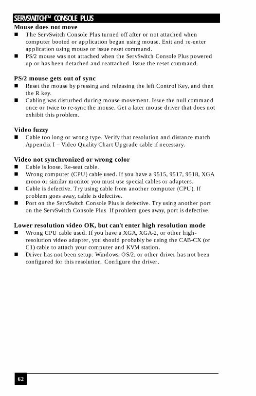
SERVSWITCH™ CONSOLE PLUS
62
Mouse does not move n The ServSwitch Console Plus turned off after or not attached when
computer booted or application began using mouse. Exit and re-enter application using mouse or issue reset command.
n PS/2 mouse was not attached when the ServSwitch Console Plus powered up or has been detached and reattached. Issue the reset command.
PS/2 mouse gets out of sync n Reset the mouse by pressing and releasing the left Control Key, and then
the R key. n Cabling was disturbed during mouse movement. Issue the null command
once or twice to re-sync the mouse. Get a later mouse driver that does not exhibit this problem.
Video fuzzy n Cable too long or wrong type. Verify that resolution and distance match
Appendix I – Video Quality Chart Upgrade cable if necessary. Video not synchronized or wrong color n Cable is loose. Re-seat cable. n Wrong computer (CPU) cable used. If you have a 9515, 9517, 9518, XGA
mono or similar monitor you must use special cables or adapters. n Cable is defective. Try using cable from another computer (CPU). If
problem goes away, cable is defective. n Port on the ServSwitch Console Plus is defective. Try using another port
on the ServSwitch Console Plus If problem goes away, port is defective. Lower resolution video OK, but can't enter high resolution mode n Wrong CPU cable used. If you have a XGA, XGA-2, or other high-
resolution video adapter, you should probably be using the CAB-CX (or C1) cable to attach your computer and KVM station.
n Driver has not been setup. Windows, OS/2, or other driver has not been configured for this resolution. Configure the driver.
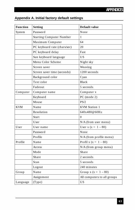
APPENDICES
63
Appendix A. Initial factory default settings Function Setting Default value
System Password None
Starting Computer Number 1
Maximum Computer 64
PC keyboard rate (chars/sec) 20
PC keyboard delay Fast
Sun keyboard language US
Menu Color Scheme Night sky
Screen saver Weaving
Screen saver time (seconds) 1200 seconds
Background color Cyan
Text color Black
Fadeout 5 seconds
Computer Computer name Computer x
Keyboard PC (mode 2)
Mouse PS/2
KVM Name KVM Station 1
Resolution 640x480@60Hz
Start 0
User N/A (from user menu)
User User name User x (x = 1 – 80)
Password None
Profile N/A (from profile menu)
Profile Name Profil x (x = 1 – 80)
Access N/A (from group menu)
Mode Share
Share 2 seconds
Scan 5 seconds
Logout 240 minutes
Group Name Group x (x = 1 – 80)
Assignment All computers to all groups
Language (Type) US
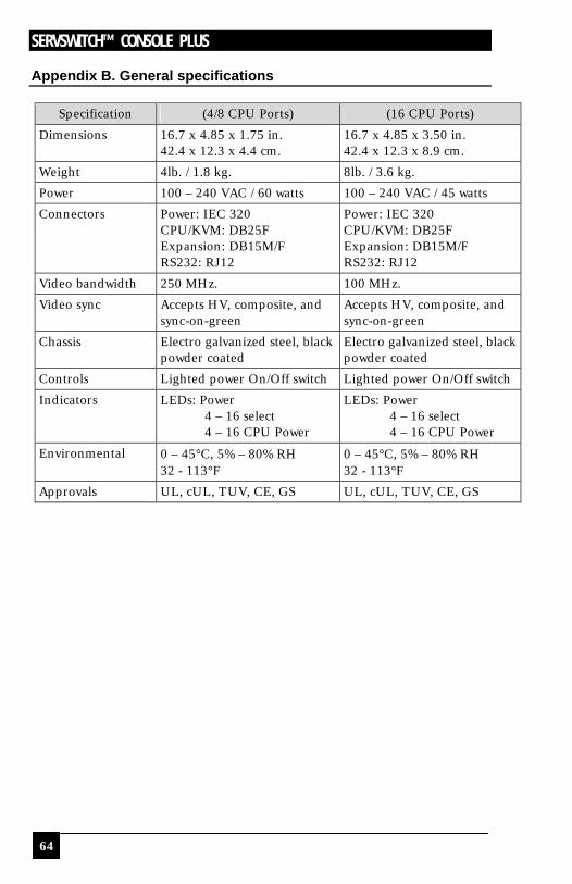
SERVSWITCH™ CONSOLE PLUS
64
Appendix B. General specifications
Specification (4/8 CPU Ports) (16 CPU Ports)
Dimensions 16.7 x 4.85 x 1.75 in. 42.4 x 12.3 x 4.4 cm.
16.7 x 4.85 x 3.50 in. 42.4 x 12.3 x 8.9 cm.
Weight 4lb. / 1.8 kg. 8lb. / 3.6 kg.
Power 100 – 240 VAC / 60 watts 100 – 240 VAC / 45 watts
Connectors Power: IEC 320 CPU/KVM: DB25F Expansion: DB15M/F RS232: RJ12
Power: IEC 320 CPU/KVM: DB25F Expansion: DB15M/F RS232: RJ12
Video bandwidth 250 MHz. 100 MHz.
Video sync Accepts HV, composite, and sync-on-green
Accepts HV, composite, and sync-on-green
Chassis Electro galvanized steel, black powder coated
Electro galvanized steel, black powder coated
Controls Lighted power On/Off switch Lighted power On/Off switch
Indicators LEDs: Power 4 – 16 select 4 – 16 CPU Power
LEDs: Power 4 – 16 select 4 – 16 CPU Power
Environmental 0 – 45°C, 5% – 80% RH 32 - 113°F
0 – 45°C, 5% – 80% RH 32 - 113°F
Approvals UL, cUL, TUV, CE, GS UL, cUL, TUV, CE, GS

APPENDICES
65
Appendix C. Parts and cables
* Cable lengths in 1, 5, 10, 20, 35, 50, 75, 100 feet ** Cable lengths in 5, 10, 20, 35, 50, 75, 100 feet *** Max cable length = 20 feet
Part number Description (Multi-Platform models)
EHN206-nnnn* Coax Sun CPU video-Kbd-mouse to DB25M
EHN215-nnnn* Apple CPU video-Kbd-mouse to DB25M
EHN225-nnnn* Coax VGA-Sun Kbd-Sun mouse
EHN242-nnnn* (Sun 13W3M) DB25M (Video only)
ENH245-nnnn* (Sun 13W3F) DB25M (Video only)
EHN485-nnnn** CPU - DB25M to HD15F / USB Type A
EHN485A-nnnn** CPU - DB25M to HD15F / USB Type A + Audio
EHN500-nnnn* SGI-KVM 13W3 / PS2
EHN501-nnnn* SGI-CPU 13W3 / PS2
EHN515-nnnn* SUN w/ VGA (HD15) Video, SUN Kbd & mouse
EHN520-nnnn* RS6000 CPU 13W3 / PS2
EHN521-nnnn* RS6000 KVM 13W3 / PS2
EHN540-nnnn* Coax Apple video-Kbd-mouse to DB25M
EHN560-nnnn* Coax Apple video-Kbd-mouse to DB25M
Part number Description (PC Models)
EHN041-nnnn** CPU - DB25M to HD15M (VGA Video only)
EHN044-nnnn* KVM - DB25M to HD15F (VGA Video only)
EHN052-nnnn* KVM - DB25M to HD15F / DIN5 / DB9 (AT-style)
EHN151-nnnn** CPU – DB25M to HD15F / PS2 Kbd / PS2 mouse
EHN151A-nnnn** CPU - DB25M to HD15F / PS2 Kbd / PS2 mouse + Audio
EHN154-nnnn*** KVM - DB25M to HD15F / PS2 Kbd / PS2 mouse
EHN154A-nnnn*** KVM - DB25M to HD15F / PS2 Kbd / PS2 mouse + Audio
EHN270-nnnn* KVM - DB25M to HD15F / DIN5 / DB9 - Coax (AT-style)
EHN282-nnnn** CPU - DB25M to HD15F / DIN5 / DB9 – Coax (AT style)
EHN283-nnnn* KVM - DB25M to HD15F/ PS2 Kbd / PS2 mouse - Coax
EHN284-nnnn* Cascading Cable DB25M to DB25M
EHN382-nnnn** CPU - DB25M to HD15F / PS2 Kbd / PS2 mouse
EHN382A-nnnn** CPU - DB25M to HD15F / PS2 Kbd / PS2 mouse + Audio
EHN383-nnnn* KVM - DB25M to HD15F / PS2 Kbd / PS2 mouse
EHN383A-nnnn* KVM - DB25M to HD15F / PS2 Kbd / PS2 mouse + Audio
PS024 110/220 VAC - Power transformer
RMKxxB 1U Rackmount kit (xx = 19, 23, or 24 in.)
RMKxxC 2U Rackmount kit (xx = 19, 23, or 24in)
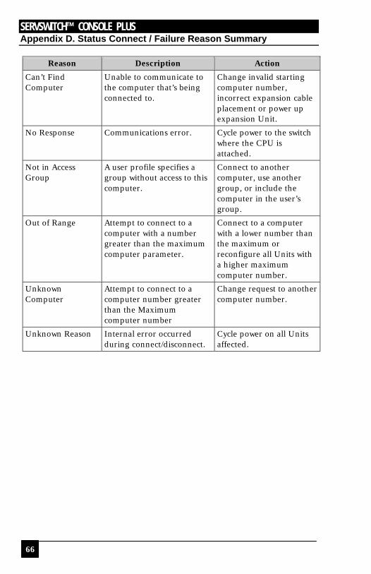
SERVSWITCH™ CONSOLE PLUS
66
Appendix D. Status Connect / Failure Reason Summary
Reason Description Action
Can’t Find Computer
Unable to communicate to the computer that’s being connected to.
Change invalid starting computer number, incorrect expansion cable placement or power up expansion Unit.
No Response Communications error. Cycle power to the switch where the CPU is attached.
Not in Access Group
A user profile specifies a group without access to this computer.
Connect to another computer, use another group, or include the computer in the user’s group.
Out of Range Attempt to connect to a computer with a number greater than the maximum computer parameter.
Connect to a computer with a lower number than the maximum or reconfigure all Units with a higher maximum computer number.
Unknown Computer
Attempt to connect to a computer number greater than the Maximum computer number
Change request to another computer number.
Unknown Reason Internal error occurred during connect/disconnect.
Cycle power on all Units affected.
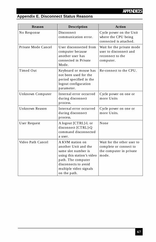
APPENDICES
67
Appendix E. Disconnect Status Reasons
Reason Description Action
No Response Disconnect communication error.
Cycle power on the Unit where the CPU being connected is attached.
Private Mode Cancel User disconnected from computer because another user has connected in Private Mode.
Wait for the private mode user to disconnect and reconnect to the computer.
Timed Out Keyboard or mouse has not been used for the period specified in the logout configuration parameter.
Re-connect to the CPU.
Unknown Computer Internal error occurred during disconnect process.
Cycle power on one or more Units
Unknown Reason Internal error occurred during disconnect process.
Cycle power on one or more Units.
User Request A logout [CTRL]-L or disconnect [CTRL]-Q command disconnected a user.
None
Video Path Cancel A KVM station on another Unit and the same slot number is using this station’s video path. The computer disconnects to avoid multiple video signals on the path.
Wait for the other user to complete or connect to the computer in private mode.

SERVSWITCH™ CONSOLE PLUS
68
Appendix F. KVM placement / conflicts It is possible, but not recommended, in an expanded system with multiple ServSwitch Console Plus switches, to connect additional KVM stations to other ServSwitch Console Plus units in the system. This allows more than one user access to the computers from multiple access locations. When doing this, all users share the same video path from switch to switch. (KVM port on ServSwitch Console Plus #1 and KVM port on ServSwitch Console Plus #3) As long as all KVM users only connect to the computers that are attached to their local ServSwitch Console Plus, they can operate with no conflicts. If a user tries to connect to a computer on a different ServSwitch Console Plus switch and a user is already connected, the video path is canceled and the ServSwitch Console Plus may not function properly, requiring a recycle of the unit’s power. If you do use multiple KVM stations, users should be made aware of the possibility of locking up the entire system.

APPENDICES
69
Appendix G. Password jumper If the configuration password is ever forgotten, the ServSwitch Console Plus switch has a special “Password” reset jumper on the CPU card. This jumper is labeled JP31 on all models. To use this jumper to bypass the password, perform the following:
1. Turn off the ServSwitch Console Plus switch and remove the top cover. 2. Install a jumper on JP31 to short the two terminals.
The login requirement will be bypassed and you will be granted access. This does not delete the password, only bypasses the function.
3. Power on the ServSwitch Console Plus with the jumper in place. 4. Call up the main menu; select “System” and press [Enter]. 5. Select “Configure password” from the configure system menu and press
[Enter]. 6. Enter a new configuration password and press [Enter]. 7. Save the new configuration password from the “Main Menu”. 8. With the new password saved, turn off the ServSwitch Console Plus switch. 9. Remove the jumper on JP31.
10. Re-install the top cover. 11. Turn the ServSwitch Console Plus on. The ServSwitch Console Plus switch
will boot up and the new password will be effective.
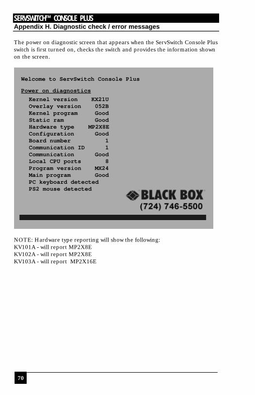
SERVSWITCH™ CONSOLE PLUS
70
Appendix H. Diagnostic check / error messages The power on diagnostic screen that appears when the ServSwitch Console Plus switch is first turned on, checks the switch and provides the information shown on the screen.
NOTE: Hardware type reporting will show the following: KV101A - will report MP2X8E KV102A - will report MP2X8E KV103A - will report MP2X16E
Welcome to ServSwitch Console Plus
Power on diagnostics Kernel version KX21U Overlay version 052B Kernel program Good Static ram Good Hardware type MP2X8E Configuration Good Board number 1 Communication ID 1 Communication Good Local CPU ports 8 Program version MX24 Main program Good PC keyboard detected PS2 mouse detected
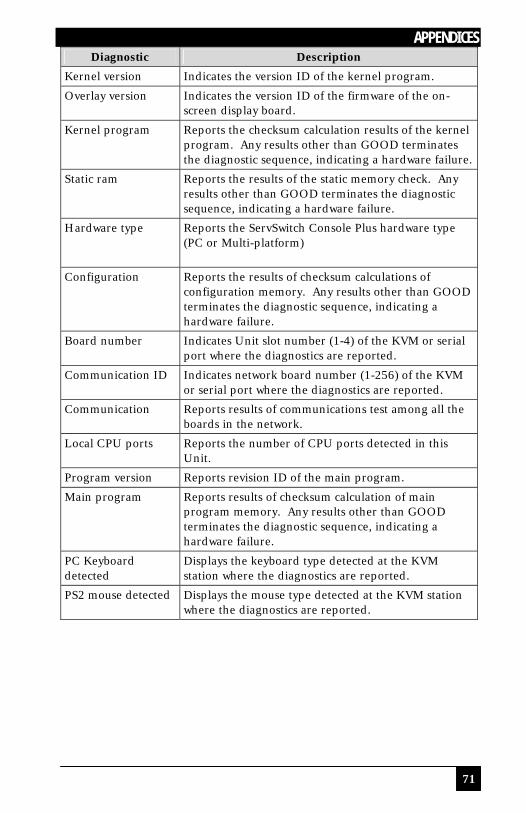
APPENDICES
71
Diagnostic Description
Kernel version Indicates the version ID of the kernel program.
Overlay version Indicates the version ID of the firmware of the on-screen display board.
Kernel program Reports the checksum calculation results of the kernel program. Any results other than GOOD terminates the diagnostic sequence, indicating a hardware failure.
Static ram Reports the results of the static memory check. Any results other than GOOD terminates the diagnostic sequence, indicating a hardware failure.
Hardware type Reports the ServSwitch Console Plus hardware type (PC or Multi-platform)
Configuration Reports the results of checksum calculations of configuration memory. Any results other than GOOD terminates the diagnostic sequence, indicating a hardware failure.
Board number Indicates Unit slot number (1-4) of the KVM or serial port where the diagnostics are reported.
Communication ID Indicates network board number (1-256) of the KVM or serial port where the diagnostics are reported.
Communication Reports results of communications test among all the boards in the network.
Local CPU ports Reports the number of CPU ports detected in this Unit.
Program version Reports revision ID of the main program.
Main program Reports results of checksum calculation of main program memory. Any results other than GOOD terminates the diagnostic sequence, indicating a hardware failure.
PC Keyboard detected
Displays the keyboard type detected at the KVM station where the diagnostics are reported.
PS2 mouse detected Displays the mouse type detected at the KVM station where the diagnostics are reported.
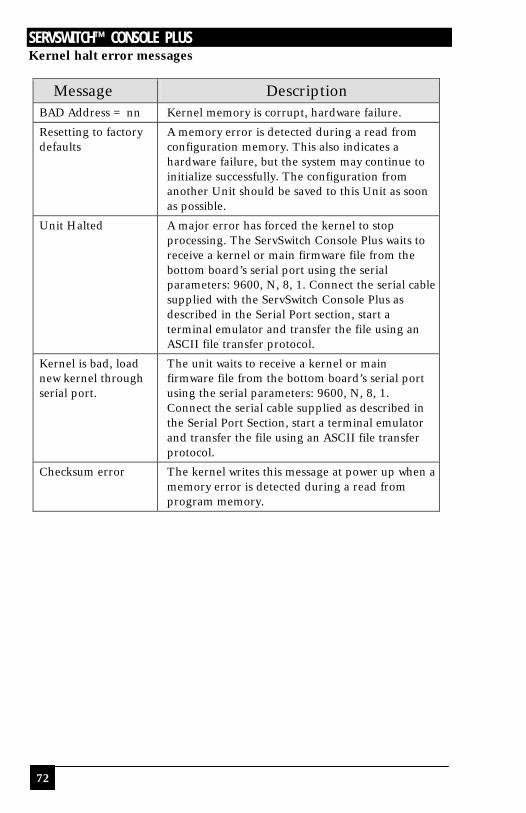
SERVSWITCH™ CONSOLE PLUS
72
Kernel halt error messages
Message Description BAD Address = nn Kernel memory is corrupt, hardware failure.
Resetting to factory defaults
A memory error is detected during a read from configuration memory. This also indicates a hardware failure, but the system may continue to initialize successfully. The configuration from another Unit should be saved to this Unit as soon as possible.
Unit Halted A major error has forced the kernel to stop processing. The ServSwitch Console Plus waits to receive a kernel or main firmware file from the bottom board’s serial port using the serial parameters: 9600, N, 8, 1. Connect the serial cable supplied with the ServSwitch Console Plus as described in the Serial Port section, start a terminal emulator and transfer the file using an ASCII file transfer protocol.
Kernel is bad, load new kernel through serial port.
The unit waits to receive a kernel or main firmware file from the bottom board’s serial port using the serial parameters: 9600, N, 8, 1. Connect the serial cable supplied as described in the Serial Port Section, start a terminal emulator and transfer the file using an ASCII file transfer protocol.
Checksum error
The kernel writes this message at power up when a memory error is detected during a read from program memory.

APPENDICES
73
Appendix I. Video distance table The limitation on extending the video distance is usually due to the quality of the video source. The table below shows the distances, resolution and quality of video that can be expected. Letters shows the cable type, and a number that refers to the quality of the video, as described below. There are further capabilities, not listed here, that will send the higher resolution video longer distances. Please contact Black Box technical support for more details. Resolution Video distance capability
@ 75Hz 5’ 10’ 20’ 35’ 50’ 75’ 100’
640x480 Z4 C4
Z4 C4
Z4 C4
Z3 C4
C4
C4
C4
800X600 Z4 C4
Z4 C4
Z4 C4
Z3 C4
C4
C4
C4
1024x768 Z4 C4
Z4 C4
Z4 C4
Z3 C4
C4
C4
C3
1280x1024 Z4 C4
Z3 C4
Z3 C4
Z3 C3 C3 C3 C2
1600x1200 Z3 C4
Z3 C3
Z2 C3
C3 C3 C2 C2
Z C
Standard cabling Coax cabling
4 Perfect or near perfect unable to easily detect defects in screen. 3 Very acceptable; images clear; small reflections around lettering
depending upon color; if you examine the screen closely you will find defects.
2 Acceptable; slightly fuzzy images; readable text, acceptable for casual use, prolonged viewing will cause eye fatigue.
1 Unusable; images smeared; text not easily readable

SERVSWITCH™ CONSOLE PLUS
74
Appendix J. Rack mount The optional rack mount kit includes the following items: n Two black anodized mounting brackets. n Four 6 - 32 x 3/8” flat head mounting screws. To rack mount your ServSwitch Console Plus switch, attach the two rack mounting brackets to your Unit with the short flange against the Unit using the four screws provided. Secure the mounting brackets to the rack using the appropriate size bolts, nuts and lock washers. Using hardware other than that provided could cause damage to the electronics and/or result in loss of mounting integrity. Do not over tighten the screws used to mount the Unit to the mounting brackets. The following general guidelines should be observed when installing your Unit into a rack. a). The ServSwitch Console Plus is designed to work in an ambient
temperature of 0ο C to 45ο C (32ο F – 113ο F). b). Do not block power supply vents or otherwise restrict airflow when rack-
mounting this Unit. c). Mechanical loading of the rack should be considered to prevent instability
and possible tipping over. d). Tighten all connectors securely and provide adequate strain relief for all
cables. e). Provide a grounded power source to all Units. Pay special attention to
overall branch circuit load ratings before connecting equipment to this source. Overloaded circuits are potential fire hazards and can cause equipment failures or poor performance.
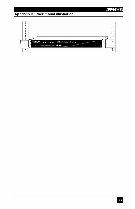
APPENDICES
75
Appendix K. Rack mount illustration

SERVSWITCH™ CONSOLE PLUS
76