the six steps of humidification design
TRANSCRIPT

To help you better understand the humidification process, this issue of Engineering Humidification will walk you through the basic steps of humidification system design, addressing the key variables – building construction, load, energy and water sources, placement and control – that affect system design. To design a system correctly, these variables must be considered and understood thoroughly.
System requirements may varyMany factors must be considered when designing a building’s humidification system. Each application will have a unique set of requirements that will affect system design. Even though individual applications will vary, the process to design a humidification system will be consistent from project to project.
The following six steps will help you properly design a humidification system for any application:
1. Review building construction
2. Determine humidification load
3. Select best energy source
4. Choose appropriate water source
5. Determine humidification system placement
6. Select the control system
STEP 1: REVIEW BUILDING CONSTRUCTION
When air and heat escape, so does humiditySimilar to protecting against unwanted heat loss in a building, there are a few things you can do to ensure accurate humidity control and to protect against unwanted condensation or loss of humidity. Whether working with new construction or in retrofit situations:
• Evaluate the vapor barrier qualities of the building you plan to humidify.
• Examine all areas of conditioned air loss, such as exhaust fans, open windows, and doors.
• Examine roof construction, especially steel supports, for poorly insulated areas that could result in condensation.
STEP 2: DETERMINE HUMIDIFICATION LOAD
Load is based on quantity of entering airProperly calculating the load ensures correct and consistent humidity levels. Undersizing will result in a system that will not maintain desired relative humidity (RH); and oversizing may cause erratic humidity levels or wet ducts, filters or fans. As a general rule, the humidification load is based on the amount of air entering a building or space and the desired RH level.
How to calculate humidification load:1. Natural ventilation method, used for buildings without a
ventilation system. The load is usually calculated using the air change method.
2. Mechanical ventilation method, used for buildings with mechanical ventilation. The load is based only on the amount of air entering a building or space.
3. Economizer cycle method, used for buildings with year-round air conditioning equipped with economizer control. The load is calculated using temperatures of outside, inside, return and mixed air.
THE SIX STEPS OF HUMIDIFICATION DESIGN
STEP 3: SELECT THE BEST BEST ENERGY SOURCE
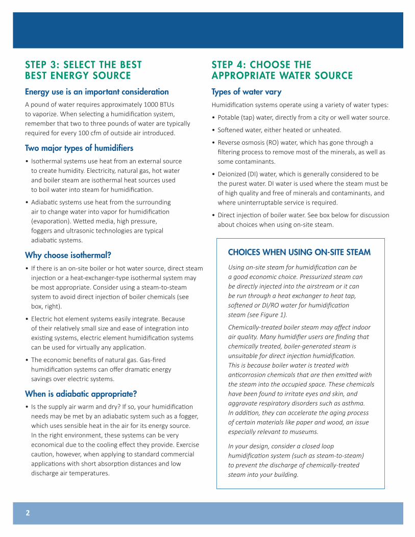
Energy use is an important considerationA pound of water requires approximately 1000 BTUs to vaporize. When selecting a humidification system, remember that two to three pounds of water are typically required for every 100 cfm of outside air introduced.
Two major types of humidifiers• Isothermal systems use heat from an external source
to create humidity. Electricity, natural gas, hot water and boiler steam are isothermal heat sources used to boil water into steam for humidification.
• Adiabatic systems use heat from the surrounding air to change water into vapor for humidification (evaporation). Wetted media, high pressure, foggers and ultrasonic technologies are typical adiabatic systems.
Why choose isothermal?• If there is an on-site boiler or hot water source, direct steam
injection or a heat-exchanger-type isothermal system may be most appropriate. Consider using a steam-to-steam system to avoid direct injection of boiler chemicals (see box, right).
• Electric hot element systems easily integrate. Because of their relatively small size and ease of integration into existing systems, electric element humidification systems can be used for virtually any application.
• The economic benefits of natural gas. Gas-fired humidification systems can offer dramatic energy savings over electric systems.
When is adiabatic appropriate?• Is the supply air warm and dry? If so, your humidification
needs may be met by an adiabatic system such as a fogger, which uses sensible heat in the air for its energy source. In the right environment, these systems can be very economical due to the cooling effect they provide. Exercise caution, however, when applying to standard commercial applications with short absorption distances and low discharge air temperatures.
STEP 4: CHOOSE THE APPROPRIATE WATER SOURCE
Types of water vary Humidification systems operate using a variety of water types:
• Potable (tap) water, directly from a city or well water source.
• Softened water, either heated or unheated.
• Reverse osmosis (RO) water, which has gone through a filtering process to remove most of the minerals, as well as some contaminants.
• Deionized (DI) water, which is generally considered to be the purest water. DI water is used where the steam must be of high quality and free of minerals and contaminants, and where uninterruptable service is required.
• Direct injection of boiler water. See box below for discussion about choices when using on-site steam.
2
CHOICES WHEN USING ON-SITE STEAM
Using on-site steam for humidification can be a good economic choice. Pressurized steam can be directly injected into the airstream or it can be run through a heat exchanger to heat tap, softened or DI/RO water for humidification steam (see Figure 1).
Chemically-treated boiler steam may affect indoor air quality. Many humidifier users are finding that chemically treated, boiler-generated steam is unsuitable for direct injection humidification. This is because boiler water is treated with anticorrosion chemicals that are then emitted with the steam into the occupied space. These chemicals have been found to irritate eyes and skin, and aggravate respiratory disorders such as asthma. In addition, they can accelerate the aging process of certain materials like paper and wood, an issue especially relevant to museums.
In your design, consider a closed loop humidification system (such as steam-to-steam) to prevent the discharge of chemically-treated steam into your building.

Water type affects performance• Mineral concentration in the supply water directly
relates to the amount of maintenance and cleaning your humidification system requires. The higher the mineral concentration, the more downtime required for cleaning. Environments that require a system to be continuously online should use demineralized (DI or RO) water. Systems using softened water can operate several seasons without the need for cleaning (yearly inspections are recommended).
STEP 5: DETERMINE HUMIDIFIER PLACEMENT The humidification system generally consists of a vapor or steam generator and a dispersion assembly. The proper placement of these two components is crucial to the operating success of the humidification process. Usually, there is no single “right” placement for a humidifier. Much depends on the system design, its uses, and its applications. However, the following paragraphs and dispersion assembly placement examples are presented as guidelines for common situations.
First, check available absorption distanceAvailable absorption distance will affect system choice. Dispersed steam must be absorbed into the airflow
before it comes in contact with any duct elbows, fans, vanes, filters, or any object that may cause condensation and dripping. Not all humidification systems guarantee absorption within a short distance, so it is important to be aware of the available absorption distance early in your design process. (See box below)
Placement of adiabatic unitsAdiabatic units need to be positioned in an AHU system where sufficient heat is available to vaporize the water being added. In most systems, this is downstream of the heating coil and upstream of the cooling coil. This allows the air to be preheated as needed. Typically, adiabatic units require an AHU extension.
3
1
2
3
4
FACTORS THAT AFFECT ABSORPTION
1. Mixing of air and steam. Uneven airflow across a dispersion unit may result in non-uniform mixing of steam with air, affecting absorption distance.
2. ∆ RH (the difference between entering and leaving RH). As ∆ increases, more humidity needs to be dispersed into the air, and thus the absorption distance increases.
3. Duct temperature. Cool air absorbs less than warm air and will require longer absorption distances.
Principle of operation:
1. Makeup water enters the evaporating chamber through the automatic water makeup valve.
2. Pressurized steam passes through the modulating steam valve to the heat exchanger. Here it causes water in the chamber to boil creating secondary, evaporative steam for humidification.
3. Condensate from the heat exchanger passes through a steam trap and is returned to the boiler.
4. Humidification steam is dispersed into the airstream.
Figure 1: Steam-to-steam evaporative humidifier

Placing a dispersion assembly in an AHU (see Figure 2)• Location A is the best choice. Installing downstream of
heating and cooling coils provides laminar flow through the dispersion unit, plus, the heated air provides an environment for best absorption. Use a multiple tube dispersion unit to ensure complete absorption of steam vapor before fan entry.
• Location B is the second-best choice. However, in change-over periods, the cooling coil may eliminate some moisture for humidification.
• Location C is the third-best choice. Air leaving a fan is usually very turbulent and may cause vapor to not absorb at the expected absorption distance. Allow for more absorption distance if installing downstream of a fan.
• Location D is the poorest choice. The cooler air at this location will require an increased absorption distance.
Duct placement near an elbow (see Figure 3)• Location A is the best choice. Better absorption will occur on the downstream side of an elbow than on the upstream side.
• Location B is the second-best choice. Installing upstream of an elbow may cause wetting at the turning vanes. In
cases where it is structurally impossible to avoid Location B, use a multiple tube dispersion unit to ensure complete absorption. Also, since more air flows along the outside “ of a turn, better absorption will occur if the humidifier discharges proportionately more steam in that part of the airstream.
• At both locations, discharging steam against or perpendicular to the airstream gives slightly better mixing and absorption than discharging with the airstream.
4
Figure 2: Placing a dispersion assembly in an AHU
Outside air
Relief air
Economizer control device
Filters Cooling coilHeating coil
Motorized air dampers
Humidity control device
8' to 12'(2.4 m to 3.7 m)
Duct high limit humidity control for dispersion Locations A, B
Airflow proving switch
Fan
Airflow proving switch
Duct high limit humidity control for dispersion Location C
Supply airflow
3' to 5'(1 m to 1.5 m)
8' to 12'(2.4 m to 3.7 m)
Return airflow
Dispersion discharges
against airflow
Preheat coil
D B A
C
Exterior building wall
8' to 12'(2.4 m to 3.7 m)
Figure 3: Placing a dispersion assembly near an elbow
Duct
Less airflow on this side of elbow
Duct high limit humidistat
3' to 5'(1 m to 1.5 m)
Mist may collect on vanes
Airflow
Dispersion discharges
againstairflow
Airflow B
A
DC-1083
DC-1081

Placement in a primary/secondary system (see Figure 4)This type of system is commonly applied to hospitals with multiple surgery rooms served by a single air handler but with individual humidity control required for each surgery room. Placement of the primary humidification system is within the main air handling unit serving the general hospital areas to a design of 70 °F and 30% RH. The secondary humidification system would be located close to the point of steam discharge into the critical care areas requiring individual humidity control.
STEP 6: SELECT THE CONTROL SYSTEMA wide range of relative humidity control (±1% to ± 5% RH) is achievable with today’s control technology; however, note that humidity control rests not only with the controls, but with the complete building system. Individual building dynamics, as mentioned in Step 1, can affect the accuracy and control of any humidification system.
Factors to consider when selecting humidity control• Desired relative humidity set-point. Typical RH
ranges are: – Comfort, static control: 35% to 40% RH
– Paper storage, printing: 40% to 50% RH – Semiconductor manufacturing: 35% to 55% RH – Health medical facilities: 35% to 50% RH
• Acceptable RH fluctuation. What is the acceptable variance from the desired RH set-point?
• Space temperature. Stable temperatures need to be maintained to accurately control humidity.
• Component quality. The control system is only as good as the least accurate component in the system. Many system difficulties can be eliminated by selecting humidity controls that match the application.
Sensor and transmitter locations are critical (see Figure 5)Sensor or transmitter location has a significant impact on humidifier performance. In most cases, we recommend that you do not interchange duct and room humidity devices. Room humidity devices are calibrated with zero or little airflow, whereas duct humidity devices require air passing across them. Recommended sensor locations:
A This is the ideal sensing location because this placement ensures the best uniform mix of dry and moist air with stable temperature control.
B This location is acceptable, but the room environment may affect controllability, such as when the sensor is too close to air grilles, registers or heat radiation from room lighting.
5
OM-784-2
Figure 4: Placement in a primary/secondary system
After humidifier: 50 °F, 60% RH
Main hospital:70 °F, 30% RHVAV
box
2000 cfm50 °F60% RH
Room transmitter:65 °F, 50% RH
Filter mixing box
Primary humidifierBefore humidifier: 50 °F, 47% RH
85,000 cfm, 50 °F, 60%
RH
Exhaust 17,000 cfmFixed outside air 17,000 cfm
83,000 cfm, 70 °F, 30% RH
Secondaryhumidifierdispersionassembly
Secondary humidifierevaporatingchamber
Criticalcare
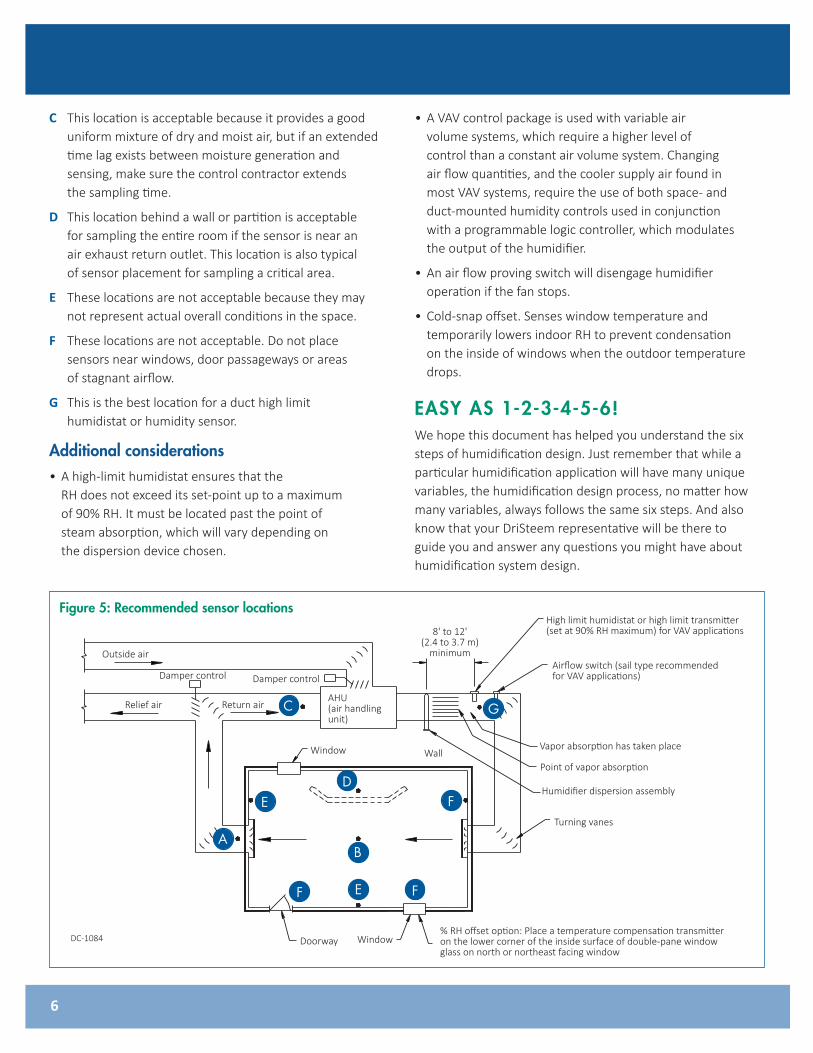
C This location is acceptable because it provides a good uniform mixture of dry and moist air, but if an extended time lag exists between moisture generation and sensing, make sure the control contractor extends the sampling time.
D This location behind a wall or partition is acceptable for sampling the entire room if the sensor is near an air exhaust return outlet. This location is also typical of sensor placement for sampling a critical area.
E These locations are not acceptable because they may not represent actual overall conditions in the space.
F These locations are not acceptable. Do not place sensors near windows, door passageways or areas of stagnant airflow.
G This is the best location for a duct high limit humidistat or humidity sensor.
Additional considerations• A high-limit humidistat ensures that the
RH does not exceed its set-point up to a maximum of 90% RH. It must be located past the point of steam absorption, which will vary depending on the dispersion device chosen.
• A VAV control package is used with variable air volume systems, which require a higher level of control than a constant air volume system. Changing air flow quantities, and the cooler supply air found in most VAV systems, require the use of both space- and duct-mounted humidity controls used in conjunction with a programmable logic controller, which modulates the output of the humidifier.
• An air flow proving switch will disengage humidifier operation if the fan stops.
• Cold-snap offset. Senses window temperature and temporarily lowers indoor RH to prevent condensation on the inside of windows when the outdoor temperature drops.
EASY AS 1-2-3-4-5-6!We hope this document has helped you understand the six steps of humidification design. Just remember that while a particular humidification application will have many unique variables, the humidification design process, no matter how many variables, always follows the same six steps. And also know that your DriSteem representative will be there to guide you and answer any questions you might have about humidification system design.
6
Figure 5: Recommended sensor locations
Outside air
Relief air
Damper control
Return airAHU(air handling unit)
Window
Point of vapor absorption
8' to 12'(2.4 to 3.7 m)
minimum
High limit humidistat or high limit transmitter (set at 90% RH maximum) for VAV applications
Airflow switch (sail type recommended for VAV applications)
Humidifier dispersion assembly
Turning vanes
% RH offset option: Place a temperature compensation transmitter on the lower corner of the inside surface of double-pane window glass on north or northeast facing window
Wall
DoorwayDC-1084
Damper control
Window
Vapor absorption has taken place
C
D
G
FE
AB
EF F
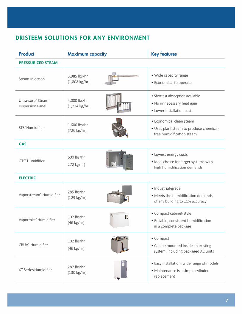
Product Maximum capacity Key features
PRESSURIZED STEAM
Steam Injection3,985 lbs/hr (1,808 kg/hr)
• Wide capacity range
• Economical to operate
Ultra-sorb® Steam Dispersion Panel
4,000 lbs/hr (1,234 kg/hr)
• Shortest absorption available
• No unnecessary heat gain
• Lower installation cost
STS® Humidifier1,600 lbs/hr (726 kg/hr)
• Economical clean steam
• Uses plant steam to produce chemical- free humidification steam
GAS
GTS® Humidifier600 lbs/hr
272 kg/hr)
• Lowest energy costs
• Ideal choice for larger systems with high humidification demands
ELECTRIC
Vaporstream® Humidifier285 lbs/hr (129 kg/hr)
• Industrial-grade
• Meets the humidification demands of any building to ±1% accuracy
Vapormist® Humidifier102 lbs/hr (46 kg/hr)
• Compact cabinet-style
• Reliable, consistent humidification in a complete package
CRUV® Humidifier102 lbs/hr
(46 kg/hr)
• Compact
• Can be mounted inside an existing system, including packaged AC units
XT Series Humidifier287 lbs/hr (130 kg/hr)
• Easy installation, wide range of models
• Maintenance is a simple cylinder replacement
7
DRISTEEM SOLUTIONS FOR ANY ENVIRONMENT
8
Form No. EH-SIXSTEPS-EN-0619
DRI-STEEM CorporationDriSteem U.S. operations are ISO 9001:2015 certified
U.S. Headquarters:14949 Technology DriveEden Prairie, MN 55344800-328-4447 or 952-949-2415952-229-3200 (fax)
European office:Marc Briers Grote Hellekensstraat 54 b B-3520 Zonhoven Belgium +3211823595 (voice) +3211817948 (fax) E-mail: [email protected]
Continuous product improvement is a policy of DriSteem Corporation; therefore, product features and specifications are subject to change without notice. DriSteem, DriCalc, Rapid-sorb, Ultra-sorb, Vapor-logic, and Vapormist are registered trademarks of Research Products Corporation and are filed for trademark registration in Canada and the European community. Drane-kooler is a trademark of DriSteem Corporation. Product and corporate names used in this document may be trademarks or registered trademarks. They are used for explanation only without intent to infringe.
© 2019 Research Products Corporation
www.dristeem.com
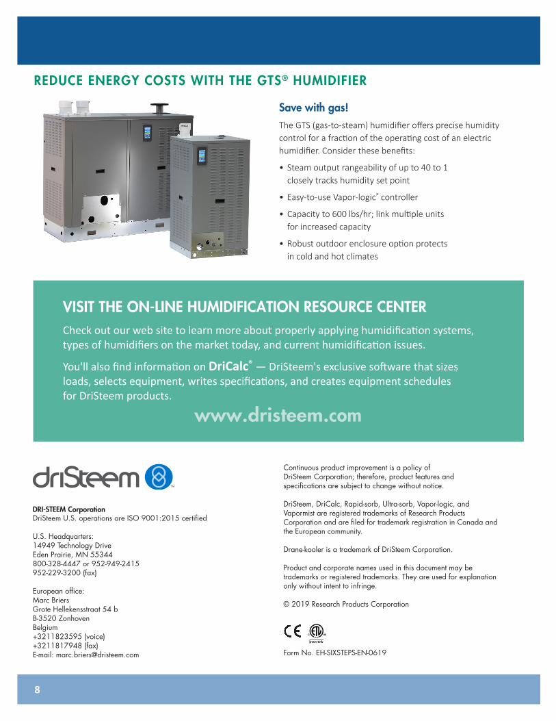
REDUCE ENERGY COSTS WITH THE GTS® HUMIDIFIER
Save with gas!The GTS (gas-to-steam) humidifier offers precise humidity control for a fraction of the operating cost of an electric humidifier. Consider these benefits:
• Steam output rangeability of up to 40 to 1 closely tracks humidity set point
• Easy-to-use Vapor-logic® controller
• Capacity to 600 lbs/hr; link multiple units for increased capacity
• Robust outdoor enclosure option protects in cold and hot climates
VISIT THE ON-LINE HUMIDIFICATION RESOURCE CENTER Check out our web site to learn more about properly applying humidification systems, types of humidifiers on the market today, and current humidification issues.
You'll also find information on DriCalc® — DriSteem's exclusive software that sizes loads, selects equipment, writes specifications, and creates equipment schedules for DriSteem products.