the smectic order of wrinkles - irepirep.ntu.ac.uk/id/eprint/31274/1/8821_goehring.pdf · the...
TRANSCRIPT
ARTICLEReceived 18 Oct 2016 | Accepted 4 May 2017 | Published 18 Jul 2017
The smectic order of wrinklesHillel Aharoni1, Desislava V. Todorova1, Octavio Albarran2, Lucas Goehring2,3, Randall D. Kamien1
& Eleni Katifori1
A thin elastic sheet lying on a soft substrate develops wrinkled patterns when subject to an
external forcing or as a result of geometric incompatibility. Thin sheet elasticity and substrate
response equip such wrinkles with a global preferred wrinkle spacing length and with
resistance to wrinkle curvature. These features are responsible for the liquid crystalline
smectic-like behaviour of such systems at intermediate length scales. This insight allows
better understanding of the wrinkling patterns seen in such systems, with which we explain
pattern breaking into domains, the properties of domain walls and wrinkle undulation. We
compare our predictions with numerical simulations and with experimental observations.
DOI: 10.1038/ncomms15809 OPEN
1 Department of Physics and Astronomy, University of Pennsylvania, Philadelphia, Pennsylvania 19104, USA. 2 Max Planck Institute for Dynamics andSelf-Organization (MPIDS), 37077 Gottingen, Germany. 3 School of Science and Technology, Nottingham Trent University, Nottingham NG11 8NS, UK.Correspondence and requests for materials should be addressed to E.K. (email: [email protected]).
NATURE COMMUNICATIONS | 8:15809 | DOI: 10.1038/ncomms15809 | www.nature.com/naturecommunications 1

The Gauss–Bonnet theorem is the bane of all mapmakers:it is impossible to represent a spherical surface on a flatplane without distorting areas or angles1. Typically, we
concern ourselves with how a flat drape or sheet can be used towrap a curved object—wrinkles2, folds and creases3 occur thatcan, by a sequence of careful pleats (origami)4 or excisions(kirigami)5, be neatly hidden or removed. This works similarly inthe reverse situation. Suppose we take half a beach ball and try tolay it flat on the table. Though the cap could elastically contractor stretch to become completely flat, our experience is that athin surface will buckle into the third dimension into patternsof wrinkles and folds.
Wrinkling allows regions that are under lateral compressionto accommodate their excess length while avoiding significant in-plane contraction. When put on a bulk of liquid, a naturallength scale for such wrinkling arises from the competitionbetween elastic bending (which tends to prefer smootherlong-wavelength wrinkles) and gravity (which pushes towardslow-amplitude wrinkles). The emergent wavenumber in such asystem is k0¼
ffiffiffiffiffiffiffiffiffiK=B4
pwhere B is the bending modulus of
the thin sheet and K is the substrate-response modulus6,7.This relation has been well studied and was generalized to caseswhere the substrate is not liquid but rather an elastic solid or,more generally, any wavelength-dependent retracting force8.It was also generalized to cases where an effective retractingforce emerges from tangential elastic tension or from substratecurvature along the wrinkle direction9,10, and was shown tohold locally even when those fields vary across the system10.In contrast, in systems without such preferred local wavelength,for example, the ‘torn garbage bag’ problem11,12, onefinds solutions which contain a wide cascade of wavelengthsspanning from scales of the non-Euclidean geometry down tothe thickness scale (or, for an infinitely thin sheet, all theway down13).
In the following we focus on systems in the regime wherethere is a scale separation between the thickness of the sheet,the periodicity k" 1
0 and the frustration length scale—either D,the lateral size of the elastic shell, or R, the smallest radiusof curvature appearing in the shell’s reference metric. If Y, Band K are the stretching, bending and substrate moduli,respectively, then this length scale separation readsffiffiffiffiffiffiffiffiffi
B=Yp
#ffiffiffiffiffiffiffiffiffiB=K4
p#D;R. Equivalently, this can be written in
terms of the Foppl–von Karman number g¼YD2/B (or YR2/B)and a stretchability parameter Z¼
ffiffiffiffiffiffiffiBKp
=Y as g" 1#Z#1.In this work we show that such systems behave like 2D smecticsat intermediate length scales, while behaving elastically atlarge length scales to satisfy global geometric constraints. Thiselastic/smectic analogy allows better understanding of theemergent wrinkle patterns, which can be faithfully interpretedin terms of grain boundaries14,15, dislocations and possibly evenfocal conic domains16 (Fig. 1). We demonstrate this fact byexplaining several features of those patterns, both qualitativelyand quantitatively. This analogy also opens a door for efficientnumerical study of these systems; the same scale separationthat poses a problem for conventional elastic simulations mayallow more efficient numerics via our smectic description.
ResultsEnergy of wrinkled patterns. Before introducing the physicalmodel, we must start with choosing a convenient coordinatesystem to represent the configuration of a thin wrinkled sheet.Such representation must be able to account for long-wavelengthdeformations to capture the overall geometry and, as we shallsee, short wavelength wrinkles that take up the excess area.For this purpose we choose surface coordinates in which the
configuration, assumed to be lying near the plane z¼ 0, takes theform
fðu; vÞ¼ðu; v; a cosfÞþ a2
8sin 2f @uf; @vf; 0ð Þ: ð1Þ
where a and f are scalar fields that in general depend on u and v.While this choice of Cartesian-like coordinates {u,v} may seemunintuitive, it can be rationalized by considering a uniformwrinkle pattern. Let the amplitude a(u,v) and wavenumberrf(u,v) be constant, that is, a(u,v)¼ a and f(u,v)¼ qu. Then thearclength of a curve along u is just
ds2¼ 1þ 12
a2q2þO a4q4" #$ %du2: ð2Þ
When the amplitude is small aq#1ð Þ, ds/du is approximatelyconstant while still capturing the overall excess length taken up bythe wrinkle. With the representation in equation (1), slowvariations in a and rf do not alter the local wrinkle features.Calculations in terms of u and v are greatly simplified because thebaseline, wrinkled metric does not have a short wavelengthdependence on u, v. This is the major advantage of using thesecoordinates, and the reason for introducing the O(a2) correctionto equation (1). In addition, it is clear from equation (1) that forsmall amplitudes the coordinates {u, v} are close to the Cartesian{x, y} coordinates of the projection of f onto the plane.
We will subsequently assume that the amplitude a(u,v)and phase f(u,v) represent a slowly varying envelope of thewrinkled pattern, namely rrfk k
jrfj2 #1 and raj jajrfj#1. We further
assume small amplitude wrinkles, namely the excess length to beD ' a2jrfj2#1. These assumptions directly relate to proper-ties of the solution rather than to controlled parameters in theproblem, but we will later show that they are consistent withresults obtained from the model in a wide parameter regimeand with solutions observed in experiments and simulations.In the following text we use the B notation to indicate equalityup to higher order terms in one or more of these smallparameters.
a b
c dI
I
1 µm
Figure 1 | Smectic patterns in wrinkles. Dislocations (a,b) andHerringbone patterns (c,d) in diblock copolymer melts (a,c) and in thinsheets on a soft elastic substrate (b,d). (a) reprinted with permission fromref. 33, copyright (2002) by the American Physical Society; (b) reprintedfrom ref. 30, with the permission of AIP Publishing, high-resolution versioncourtesy of S. Yang; (c) reprinted with permission from ref. 15, copyright(1994) American Chemical Society, high-resolution version courtesy ofS. Gido; (d) courtesy of J.A. Rogers.
ARTICLE NATURE COMMUNICATIONS | DOI: 10.1038/ncomms15809
2 NATURE COMMUNICATIONS | 8:15809 | DOI: 10.1038/ncomms15809 | www.nature.com/naturecommunications

With the above assumptions, the 2D metric and curvaturetensors of configuration (1) take the form
gij ¼ @if ( @jf ) dijþa2
2@if@jfþ
a2
4sin 2f@ijf; ð3Þ
bij ¼ @ijf ( n) a cosf @if@jf ð4Þwith i, jA{u,v}, and n the unit vector normal to the surface.Keeping our assumed scale separation in mind, we willbe interested in looking at coarse-grained versions of differentfields, namely ones which are averaged over oscillations atthe wrinkle length scale |rf|" 1, and have only featureswhich persist across at least several wrinkles. For that purposewe define a coarse-graining operator XðcgÞ¼: Oj j" 1R
O X dS,where O is a region of radius \|rf|" 1 around each pointand X can be any tensor field. Scale separation renders thisdefinition unambiguous; the sheet’s reference metric (and ofcourse the planar metric) can be approximated as Euclideanat the scale of O (since rad(O)ooD) and therefore integration,even of tensor fields, is well-defined. Since on the scale ofO the envelope of a, rf can be considered constant, while f
itself changes significantly, this coarse-graining operationwill be manifested in the vanishing of all high-frequency modespeinf(u,v), where nZ1, in X. For tensor fields this can be doneelement-wise in coordinates. Applying this to the metric (3) andcurvature (4) tensors yields
gðcgÞij ¼@ijþ
a2
2@if@jf and bðcgÞ
ij ¼0: ð5Þ
Let us now assume a scenario in which a thin elasticnon-Euclidean shell is put atop a bulk of liquid (Fig. 2).The system energy H takes contributions from both the elasticenergy of the thin sheet—stretching and bending17,18—and fromthe gravitational potential energy associated with displacingliquid elements (perfect wetting of the sheet is assumed). It cantherefore be written in the form
H¼Z
UsþUbð Þffiffiffiffiffiffiffiffiffiffidet g
pdu dvþ
ZUg dx dy; ð6Þ
a b
c d
–21 cm
DR
y
!
" (u, !)
x
–1 1 2
0.1
0.2
0.3
0.4k0
2z 2
u (cm)
e
f g
∆ (!, u)
0.4
0.3
0.2
0.1
0
2π
2π∇"
∇"
L
≈λ0
a u
u
!
Figure 2 | Non-Euclidean shells on a Euclidean substrate. (a) A spherical shell laid atop a flat body of water may develop wrinkles as means to overcomethe geometric incompatibility. We denote by D the typical size of the shell and by R its radius of curvature. (b) We choose coordinates {u, v}, which at largescales follow the Cartesian coordinates {x, y} of the projection, however, at sub-wrinkle scales are proportional to arclength coordinates on the sheet. The
amplitude a(u, v) and wave vector 2prf (written as in terms of a phase field f(u, v)) may significantly vary across the sheet, however, the wavelength 2p
rfj j has
a universal preferred value l0. (c) Experiment: a hexagonal D¼6 cm patch was cut out of a 30 mm-thick PDMS spherical shell, R¼6 cm, before laid atopwater. Shown is a top view schlieren image of the equilibrium configuration. (d) Simulation: a finite-element code with the physical parameters of theexperiment (c). Shown is the vertical displacement from the plane. A single wrinkle (solid line) may bend, that is, change its in-plane direction, with wrinklecurvature encoded in the second derivatives of the phase field f. In the shown example, the obtained pattern breaks into six domains, such as the lightenedregion on the right. Wrinkle bending focuses into domain walls (thicker solid segment of the wrinkle line). We denote by L the typical domain size. (e) The
height squared profile of (d), at two different slices (horizontal and vertical), normalized by k20. The envelope of these curves is by definition D(u, v). The
black curve, D ¼ 2u2
R2 " u2, plotted for R¼6 cm (no fitted parameters), is anticipated for an axisymmetric pattern. (f) The full D(u, v) measured from (d).
(g) Sketch of the phase field f(u, v) for the pattern in (c,d). Level sets of f indicate wrinkles.
NATURE COMMUNICATIONS | DOI: 10.1038/ncomms15809 ARTICLE
NATURE COMMUNICATIONS | 8:15809 | DOI: 10.1038/ncomms15809 | www.nature.com/naturecommunications 3
where
Us¼Y8
g" gk k2; ð7Þ
Ub¼B2
b" b&& &&2
; ð8Þ
Ug¼K2
f ( zð Þ2: ð9Þ
For an isotropic material the stretching modulus is Y¼ Et1" n2
(with E Young’s modulus, t the thickness and n Poisson’s ratio),bending modulus is B¼ Et3
12 1" n2ð Þ, and substrate modulus is K¼ rg(fluid density and gravitational acceleration, respectively).The parameters g and b are the shell’s reference metricand curvature tensors, respectively, and Xk k2¼ X;Xh i whereX;Yh i¼ð1" nÞtr XY½ + þ n tr X½ +tr Y½ + and tr denotes contraction
with the contravariant reference metric tensor gij. Note that thegravitational potential is not proportional to
ffiffiffiffiffiffiffiffiffiffidet g
p, and that it is
not fully determined by the surface’s fundamental forms, becauseof the non-covariance of the liquid (in the 2D geometry). Thedifference between its proper area form dx dy and our coordinatearea form du dv is high-order in our small parameters and will beneglected in the following. Substituting equation (5) intoequations (7)–(9) yields
Us)Y8
gðcgÞ " g&& &&2þ Ya2
16sin 2f gðcgÞ " g;rrf
D E;
þ Ya4
12sin22f rrfk k2;
ð10Þ
Ub)B2
b&& &&2þ Ba
2cosf b;rfrf
' (
þ Ba2
2cos2 f rfrfk k2;
ð11Þ
Ug)Ka2
2cos2 f; ð12Þ
where (rrf)ij¼ @ijf and (rfrf)ij¼ @if@jf (it is worthnoting that krfrfk¼jrfj2). Under our assumed scaleseparation, the Hamiltonian (6) (or any large-scale integral) isunchanged by coarse-graining its integrand, thus we can rewriteequations (6) and (10)–(12):
H¼Z
U ðcgÞ du dv; ð13Þ
where
U ðcgÞ¼ UsþUbð Þffiffiffiffiffiffiffiffiffiffidet g
pþUg
h iðcgÞ
) Y8
gðcgÞ " g&& &&2þ B
2b&& &&2
þ Ya4
256rrfk k2þ Ba2
4rfj j4þ Ka2
4:
ð14Þ
With our thinness and slowly varying envelope assumptions, themodulus Y that appears in the first term of equation (14) is muchlarger than the other moduli in equation (14). It follows thatkgðcgÞ " gk # 1, hence that the value of the local excess lengthD¼ a2|rf|2 is nearly constrained locally (see SupplementaryNote 1 for a detailed derivation). Under this constraint, thebending and gravity terms in equation (14) are minimized at thewell-studied finite wavenumber k0¼
ffiffiffiffiffiffiffiffiffiK=B4
p, around which we can
expand these terms.
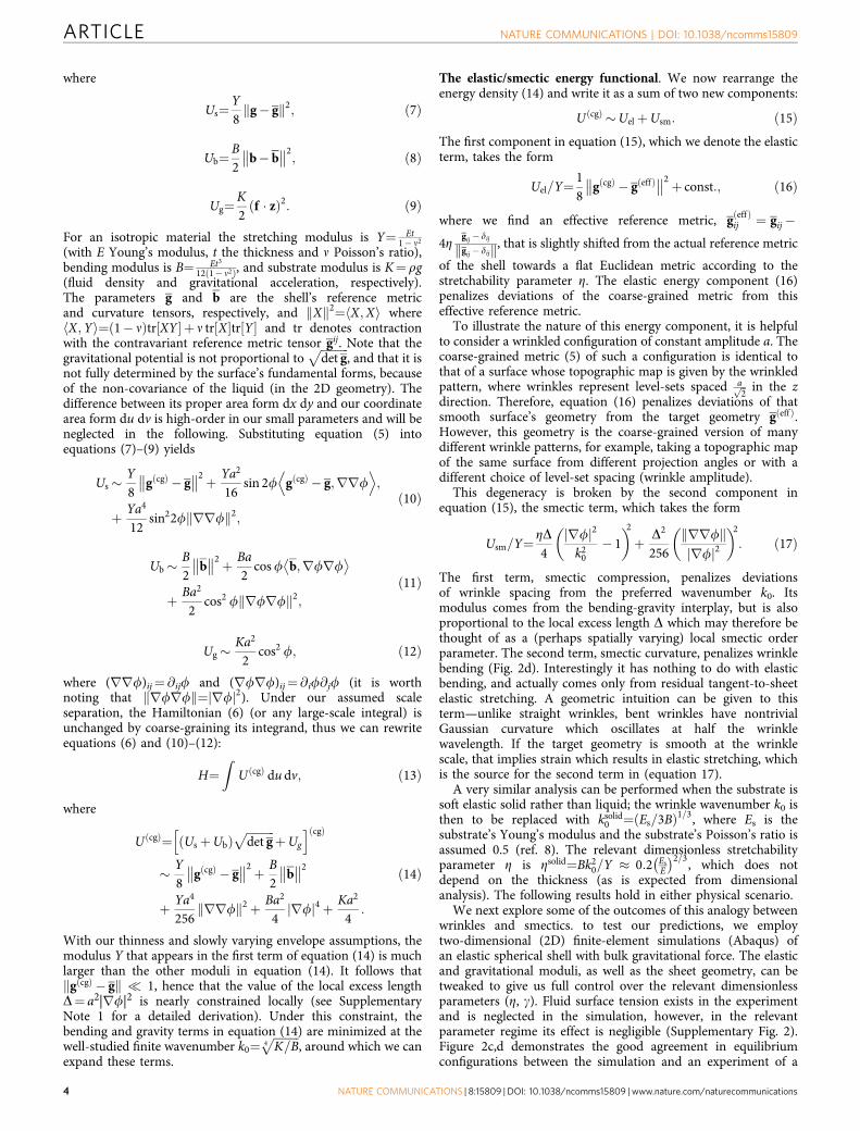
The elastic/smectic energy functional. We now rearrange theenergy density (14) and write it as a sum of two new components:
U ðcgÞ )UelþUsm: ð15Þ
The first component in equation (15), which we denote the elasticterm, takes the form
Uel=Y¼ 18
gðcgÞ " gðeffÞ&& &&2þ const:; ð16Þ
where we find an effective reference metric, gðeffÞij ¼ gij"
4Z gij " dij
gij " dijk k, that is slightly shifted from the actual reference metric
of the shell towards a flat Euclidean metric according to thestretchability parameter Z. The elastic energy component (16)penalizes deviations of the coarse-grained metric from thiseffective reference metric.
To illustrate the nature of this energy component, it is helpfulto consider a wrinkled configuration of constant amplitude a. Thecoarse-grained metric (5) of such a configuration is identical tothat of a surface whose topographic map is given by the wrinkledpattern, where wrinkles represent level-sets spaced affiffi
2p in the z
direction. Therefore, equation (16) penalizes deviations of thatsmooth surface’s geometry from the target geometry gðeffÞ.However, this geometry is the coarse-grained version of manydifferent wrinkle patterns, for example, taking a topographic mapof the same surface from different projection angles or with adifferent choice of level-set spacing (wrinkle amplitude).
This degeneracy is broken by the second component inequation (15), the smectic term, which takes the form
Usm=Y¼ ZD4rfj j2
k20" 1
) *2þ D2
256rrfk krfj j2
) *2
: ð17Þ
The first term, smectic compression, penalizes deviationsof wrinkle spacing from the preferred wavenumber k0. Itsmodulus comes from the bending-gravity interplay, but is alsoproportional to the local excess length D which may therefore bethought of as a (perhaps spatially varying) local smectic orderparameter. The second term, smectic curvature, penalizes wrinklebending (Fig. 2d). Interestingly it has nothing to do with elasticbending, and actually comes only from residual tangent-to-sheetelastic stretching. A geometric intuition can be given to thisterm—unlike straight wrinkles, bent wrinkles have nontrivialGaussian curvature which oscillates at half the wrinklewavelength. If the target geometry is smooth at the wrinklescale, that implies strain which results in elastic stretching, whichis the source for the second term in (equation 17).
A very similar analysis can be performed when the substrate issoft elastic solid rather than liquid; the wrinkle wavenumber k0 isthen to be replaced with ksolid
0 ¼ Es=3Bð Þ1=3, where Es is thesubstrate’s Young’s modulus and the substrate’s Poisson’s ratio isassumed 0.5 (ref. 8). The relevant dimensionless stretchabilityparameter Z is Zsolid¼Bk2
0=Y , 0:2 EsE
" #2=3, which does notdepend on the thickness (as is expected from dimensionalanalysis). The following results hold in either physical scenario.
We next explore some of the outcomes of this analogy betweenwrinkles and smectics. to test our predictions, we employtwo-dimensional (2D) finite-element simulations (Abaqus) ofan elastic spherical shell with bulk gravitational force. The elasticand gravitational moduli, as well as the sheet geometry, can betweaked to give us full control over the relevant dimensionlessparameters (Z, g). Fluid surface tension exists in the experimentand is neglected in the simulation, however, in the relevantparameter regime its effect is negligible (Supplementary Fig. 2).Figure 2c,d demonstrates the good agreement in equilibriumconfigurations between the simulation and an experiment of a
ARTICLE NATURE COMMUNICATIONS | DOI: 10.1038/ncomms15809
4 NATURE COMMUNICATIONS | 8:15809 | DOI: 10.1038/ncomms15809 | www.nature.com/naturecommunications

PDMS shell on water, performed with the same physicalparameters. An extensive experimental and numerical researchof such systems is in progress.
Domain walls. From the two smectic moduli in equation (17),one can extract a smectic penetration length
lpen¼
ffiffiffiffiffiffiffiffiffiffiffiffiffiffiffiffiffiffiffiffiffiffiffiffiffiffiffiffiffiffiffiffiffiffiffiffiffiffiffiffiffifficurvature modulus
compression modulus
s
¼ffiffiffiffiffiffiffiffiffiD=Z
p
16pl0; ð18Þ
where l0 is the wrinkle wavelength. The penetration length lpen isa typical length over which smectic layers—or wrinkles—maybend smoothly. Hence, the wall between two smectic domains,with an angle difference 2o#1 between their wrinkledirections, will be of typical width 2lpen/tano (ref. 19). Fromequation (18) one learns that domain wall width is proportionalto
ffiffiffiffiDp
, hence proportional to the amplitude. In systems with anon-Euclidean underlying geometry, the amplitude may varyacross the system (since gðcgÞ , gðeffÞ). Consequently domainwalls may vary in width, possibly even along one continuouswall, as can be well seen in Fig. 3a. Remarkably, equation (18),based entirely on the theory of smectic liquid crystals, providesa precise prediction for the relation between the width of
domain walls and local amplitude in wrinkled patterns. Thisprediction is in excellent agreement with measurements taken onour wrinkled elastic sheet simulations (Fig. 3c).
As Fig. 3 suggests, the above prediction appears to be valid onlyabove certain values of the parameter Z. Nonetheless, itsbreakdown is also explained by smectic theory; indeed, manysystems that exhibit layered patterns, ranging from diblockcopolymer melts15,20,21 to Rayleigh–Benard convection22,23, showa transition from ‘Chevron’-shaped domain walls at small wallangles to O-shaped walls at large angles. This bifurcation isachieved via the formation of a pair of disclinations at each layer,to better maintain layer spacing in the system. A similartransition was observed, though to the best of our knowledgenot explicitly discussed, in wrinkled herringbone patterns24,25,seemingly via the formation of d-cones (ref. 26). The criticaldomain boundary angle for this transition is made wider whenthe thickness of the sheet (or equivalently Z) increases, thus notallowing focusing of the curvature into small d-cones cores. Sincethe width of the O-shaped domain wall scales as the wrinklewavelength l0, and not as the penetration length, one expectsdomain walls to abruptly change their scaling with decreasing Z,as seen in Fig. 3. For wider domain wall angles, the Chevron-typewalls and consequently the width plpen relation are expected topersist onto narrower sheets.
Undulation instability. In smectic systems, certain boundaryconditions may induce an undulation instability in the smecticstructure27,28. At its onset, the wavelength of this undulation is
lund /ffiffiffiffiffiffiffiffiffiffiffilpend
q/ Z" 1=4
ffiffiffiffiffiffiffil0d
p; ð19Þ
where the d is a system scale at which boundary conditionsare introduced. To test if similar behaviour exists in wrinkledsystems, we designed a numerical experiment (Fig. 4) thatfollows the footsteps of ref. 27 in their smectic-A experiment. Inour simulations, we hold a thin strip at its boundaries at awavelength lB which is slightly mismatched with the preferredwrinkle spacing l0¼ 0.95lB. One resolution for such mismatchmay be an undulation, which allows layer spacing in the bulk tobe smaller than on the boundary, while paying some cost for layerbending. The predicted optimum for this exchange is givenby equation (19). We examine a sequence of systems withfixed geometry and wrinkle wavelength, however, withpenetration/undulation lengths varying between simulations(achieved via changing both fluid density and sheet thickness sothat l0 remains constant, however, Z changes).
Indeed, an undulation in the wrinkling pattern appears(Fig. 4a). The observed undulation wavelength scales as thesquare root of the penetration length (Fig. 4b), as accuratelypredicted by equation (19). When using the ribbon width as asurrogate for the system scale d, we get a factor of E1.7 betweenthe observed wavelength and the predicted one, asserting thatribbon width may not be the relevant system scale.
We further observe that wrinkle undulations spontaneouslyappear in certain regions of larger systems with free boundaryconditions as a result of the global geometric incompatibility.We show examples for this observation in Fig. 4c and inSupplementary Fig. 1. We conjecture that this instability sets thescale for the herringbone patterns seen in biaxially compressedsheets on elastic substrates25,29,30, as shown in Fig. 1d. The scalingimplied by this conjecture agrees with the stability analysis scalingpresented in ref. 31.
Domain size scaling. Last, our smectic analogy approachcan further give a coarse prediction for the typical size andnumber of domains in systems that wrinkle as a result of
0.0 0.5 1.0 1.5 2.0 2.5
2#pen/#0
0.2
0.4
0.6
0.8
1.0
1.2
1.4
Wid
th/#
0
$ = 2.5 × 10⁻⁴
$ = 2.4 × 10⁻⁴
$ = 1.8 × 10⁻⁴
$ = 5.7 × 10⁻⁵
$ = 3.8 × 10⁻⁵
z (#0)
–1
10
– 120
0
120
110
H (1/#0)
–3–2–10123
a b
c
Figure 3 | The width of domain walls. (a,b) Equilibrium wrinkle patterns ina square section of a spherical shell on liquid substrate (simulation).Vertical displacement z (top-left) and mean curvature H (bottom-right)clearly indicate splitting of the patterns into four domains divided bydomain walls of varying widths. (a) ZE2.4- 10"4, all domain walls are ofthe ‘Chevron’ type, that is, wrinkle angle changes monotonically whenmoving along the wrinkle across a domain wall. (b) ZE5.7- 10" 5, domainwalls in the high-amplitude wrinkles become O-shaped through theformation of localized d-cones (cusp is well seen in the mean curvaturemap). (c) The width of Chevron-shaped domain walls is proportional to thepenetration length (equation (18)), hence to the amplitude. O-shaped wallshave widths proportional to the wrinkle wavelength, regardless of theamplitude. Widths are extracted from simulations by fitting wrinkle angle toan arctangent, in compliance with19. Penetration lengths are calculated fromsystem parameters and the measured amplitude of each wrinkle.
NATURE COMMUNICATIONS | DOI: 10.1038/ncomms15809 ARTICLE
NATURE COMMUNICATIONS | 8:15809 | DOI: 10.1038/ncomms15809 | www.nature.com/naturecommunications 5

geometric incompatibility. The coarse-grained metric g(cg) of adomain-type patterns is approximately that of a piecewise-linearconfiguration that approximates the curved target metric gðeffÞ.The strain that results from the difference between the twoinduces the elastic energy (16), therefore preferring smallerdomains (that is, a better piecewise-linear approximation).However, the smectic energy term (17) is concentrated intodomain walls, thus penalizing many-domain solutions. Theinterplay between these two contributions sets the typicaldomain size.
We consider a spherical shell with radius of curvature R. Fordomains of typical size L, the maximal (average) elastic strainscales as p L2R" 2 (R" 2 is the Gaussian curvature mismatch).Integrated over the entire sheet of typical size D, this will result intotal elastic energy Uel / D2L4
R4 . The energy per-unit-length of adomain wall is proportional to the smectic curvature modulusdivided by the smectic penetration length19, that is, scalesas pD3/2Z1/2l0pD3/2t. Upon introducing the typical excesslength implied by the global geometric incompatibility, D / D2
R2 ,and the total length of the walls pD2/L, we get the total smecticcontribution Usm / tD5
LR3. Minimization of the total energy (15)suggests the scaling
L=D / ðR=DÞ1=5g" 1=10; ð20Þ
where g is the Foppl–von Karman number. This general scalingrelation should be taken with caution, since the number ofdomains is discrete and is very much affected by boundaryconditions. A quantitative experimental or numerical verificationof equation (20) must therefore involve very large systems(so that boundary effects are irrelevant), with typical domain sizeextracted via statistical analyses of the pattern. Anotherexperimental complication involves the very small exponent bywhich the domain size in equation (20) depends on physicalparameters. Preliminary numerical observations may supportrelation (20) (Fig. 5), however, a robust numerical verificationusing a finite-element thin-sheet simulation is computationallyinconceivable as a result of the extreme multi-scale nature of theproblem. Nevertheless, we hope that a more efficient simulationbased on our phase field f approach may in the future allowverification of this scaling.
DiscussionWe have shown that thin elastic systems that develop wrinkledpatterns share similar physics to that of smectic liquidcrystals and other stripe-patterned systems over a wide parameterregime. The analogy allows us to make quantitative predictionsregarding several aspects of wrinkled patterns. Not lessimportantly, it sheds new light on the behaviour of such systems,and extends our intuition about the emerging patterns observedin them. We show numerically that behaviour typical to smecticsystems is indeed evident in wrinkled patterns.
Our theory relies on several key assumptions, primarily thescale separation between the wrinkle wavelength and other scales.These include not only controlled system parameters such as thesheet dimensions or intrinsic geometry radii of curvature, but also
% ≈ 3.5 × 10⁶% ≈ 1.4 × 10⁷
% ≈ 3.9 × 10⁷ % ≈ 8.8 × 10⁷
Figure 5 | Domain size scaling. Typical equilibrium wrinkle patterns in ahexagonal section of a thin spherical shell on a liquid substrate. Allsimulation parameters are kept fixed, except for the sheet thickness. TheFoppl–von Karman number g of the system is indicated above each pattern.While the top-left pattern is clearly divided into six domains, increasing gseems to decrease the typical domain size. The scale bar to the right ofeach pattern shows the scaling of typical domain sizes predicted byequation (20), up to a constant factor (only the ratios between bars aremeaningful since equation (20) suggests only the scaling of the typical sizeand leaves the prefactor unknown).
3#0
5#0
7#0
12
10
8
6
4
2
00 1 7
MeasuredFitted slope ! 1.71
6543
#und/#0 (predicted)
# und
/#0
(mea
sure
d)
2
#predund
= 4#0#predund
#0 = 0.95#B#Bz (#0)
– 110
– 120
0
120
110
a
b c
Figure 4 | Undulation instability. (a) Equilibrium wrinkle patterns in a flatthin ribbon residing on a flat body of water (simulation), held at its far endswith a fixed wavy boundary. The preferred wrinkle wavelength l0 is5% shorter than the boundary wavelength lB. Shown are the results for
various values of the predicted undulation wavelength lpredund ¼
ffiffiffiffiffiffiffiffiffiffiffilpend
p
(equation (19)), where the ribbon’s width is used as a surrogate for thesystem scale d. (b) The measured undulation wavelength is plotted againstthe predicted one. While corroborating the predicted scaling, the measured
wavelength is consistently larger thanffiffiffiffiffiffiffiffiffiffiffilpend
pby a factor of E1.7,
suggesting that the relevant system scale d may be different than theribbon width by a constant factor. (c) Simulation results for a sphericalcap with free boundary conditions. An undulation appears spontaneously,and its observed wavelength (black triangles) agrees with the predictedvalue, where the shell’s diameter appears to be a good surrogate for thesystem scale d.
ARTICLE NATURE COMMUNICATIONS | DOI: 10.1038/ncomms15809
6 NATURE COMMUNICATIONS | 8:15809 | DOI: 10.1038/ncomms15809 | www.nature.com/naturecommunications

emergent length scales such as the amplitude or the variation inthe pattern’s envelope. These assumptions hold globally in manysystems, as we showed in this paper. In other parameter regimesthese assumptions break, with an apparent tendency to localizeinto small regions in the form of deep folds or creases. Theselocalized structures cannot be accounted for by including higherorders in the small parameters we introduced. Their geometricalfeatures as well as their energetic contribution must be estimatednon-perturbatively to understand when the formation of suchstructures is favourable—fodder for future work.
In addition, if one wishes to predict more precisely the emergentpatterns, and not just their general features and bulk statistics, it isnecessary to formulate the effective boundary conditions for thesmectic model. These rules may be complicated as they involveboth the smectic phase field and the residual elastic strain fieldcoupled together and will, in many cases, involve the appearance ofa non-wrinkled flattened boundary layer32. They are therefore inneed of further investigation. Formulating these boundaryconditions and combining them with the bulk equationspresented in this paper will complete the description of wrinkledsystems on soft substrates in terms of only smooth fields in the 2DEuclidean plane. It may therefore be a basis for simple and efficientnumerical simulations of these systems that will allow furtherinvestigation of their rich pattern phenomenology.
Data availability. The data that support the findings of this studyare available from the corresponding authors upon reasonablerequest.
References1. Do Carmo, M. P. Differential Geometry of Curves and Surfaces (Prentice Hall,
1976).2. King, H., Schroll, R. D., Davidovitch, B. & Menon, N. Elastic sheet on a liquid
drop reveals wrinkling and crumpling as distinct symmetry-breakinginstabilities. Proc. Natl Acad. Sci. USA 109, 9716–9720 (2012).
3. Pocivavsek, L. et al. Stress and fold localization in thin elastic membranes.Science 320, 912–916 (2008).
4. Lang, Robert J. in Proceedings of the Twelfth Annual Symposium onComputational Geometry 98–105 (1996).
5. Castle, T. et al. Making the cut: lattice Kirigami rules. Phys. Rev. Lett. 113,245502 (2014).
6. Biot, M. A. Bending of an infinite beam on an elastic Foundation. J. Appl. Math.Mech. 203, A-1–A-7 (1937).
7. Milner, S. T., Joanny, J. F. & Pincus, P. Buckling of Langmuir monolayers.Eur. Lett. 9, 495–500 (1989).
8. Brau, F., Damman, P., Diamant, H. & Witten, T. A. Wrinkle to fold transition:influence of the substrate response. Soft Matter 9, 8177 (2013).
9. Cerda, E. & Mahadevan, L. Geometry and physics of wrinkling. Phys. Rev. Lett.90, 074302 (2003).
10. Paulsen, J. D. et al. Curvature-induced stiffness and the spatial variation ofwavelength in wrinkled sheets. Proc. Natl Acad. Sci. USA 113, 1144–1149(2016).
11. Sharon, E., Roman, B., Marder, M., Shin, G.-S. & Swinney, H. L. Bucklingcascades in free sheets. Nature 419, 579 (2002).
12. Audoly, B. & Boudaoud, A. Self-similar structures near boundaries in strainedsystems. Phys. Rev. Lett. 91, 086105 (2003).
13. Gemmer, J., Sharon, E., Shearman, T. & Venkataramani, S. C. Isometricimmersions, energy minimization and self-similar buckling in non-Euclideanelastic sheets. Europhys. Lett. 114, 24003 (2016).
14. Renn, S. R. & Lubensky, T. C. Abrikosov dislocation lattice in a model of thecholesteric to smectic-A transition. Phys. Rev. A 38, 2132–2147 (1988).
15. Gido, S. P. & Thomas, E. L. Lamellar diblock copolymer grain boundarymorphology tilt boundaries. Macromolecules 27, 6137–6144 (1994).
16. Friedel, G. The mesomorphic states of matter. Ann. Phys. 18, 163–174 (1922).17. Efrati, E., Sharon, E. & Kupferman, R. Elastic theory of unconstrained
non-Euclidean plates. J. Mech. Phys. Solids 57, 762–775 (2009).18. Dervaux, J., Ciarletta, P. & Amar, M. B. Morphogenesis of thin hyperelastic
plates: a constitutive theory of biological growth in the Foppl-von Karmanlimit. J. Mech. Phys. Solids 57, 458–471 (2009).
19. Blanc, C. & Kleman, M. Curvature walls and focal conic domains in a lyotropiclamellar phase. Eur. Phys. J. B 10, 53–60 (1999).
20. Matsen, M. W. Kink grain boundaries in a block copolymer lamellar phase.J. Chem. Phys. 107, 8110–8119 (1997).
21. Tsori, Y., Andelman, D. & Schick, M. Defects in lamellar diblockcopolymers: Chevronand -shaped tilt boundaries. Phys. Rev. E 61, 2848ð2000Þ:
22. Ercolani, N., Indik, R., Newell, A. C. & Passot, T. Global description ofpatterns far from onset: a case study. Phys. D Nonlinear Phenom. 184, 127–140(2003).
23. Ercolani, N. M. & Venkataramani, S. C. A variational theory for point defects inpatterns. J. Nonlinear Sci. 19, 267–300 (2009).
24. Yang, S., Khare, K. & Lin, P.-C. Harnessing surface wrinkle patterns in softmatter. Adv. Funct. Mater. 20, 2550–2564 (2010).
25. Chen, X. & Hutchinson, J. W. Herringbone buckling patterns of compressedthin films on compliant substrates. J. Appl. Mech. 71, 597 (2004).
26. Amar, M. B. & Pomeau, Y. Crumpled paper. Proc. R Soc. Lond. A 453, 729–755(1997).
27. Delaye, M., Ribotta, R. & Durand, G. Buckling instability of the layers in asmectic-A liquid crystal. Phys. Lett. A 44, 139–140 (1973).
28. Oswald, P. & Ben-Abraham, S. I. Undulation instability under shear in smecticA liquid crystals. J. Phys 43, 1193–1197 (1982).
29. Choi, W. M. et al. Biaxially stretchablewavy silicon nanomembranes. Nano Lett.7, 1655–1663 (2007).
30. Lin, P. C. & Yang, S. Spontaneous formation of one-dimensional ripples intransit to highly ordered two-dimensional herringbone structures throughsequential and unequal biaxial mechanical stretching. Appl. Phys. Lett. 90,18–21 (2007).
31. Mahadevan, L. & Rica, S. Self-organized origami. Science 307, 1740 (2005).32. Efrati, E., Sharon, E. & Kupferman, R. Buckling transition and boundary layer
in non-Euclidean plates. Phys. Rev. E 80, 16602 (2009).33. Harrison, C. et al. Dynamics of pattern coarsening in a twodimensional smectic
system. Phys. Rev. E 66, 011706 (2002).
AcknowledgementsWe thank B.Davidovitch and S.Venkataramani for helpful discussions. We thank S.Yang,S.Gido and J.A.Rogers for sharing high-resolution images of their experiments with us.H.A. and R.D.K. were supported by NSF DMR-1262047. D.V.T. and E.K. were supportedby the NSF Award PHY-1554887, NSF MRSEC Grant DMR-1120901 and the BurroughsWellcome Career Award. This work was partially supported by a Simons Investigatorgrant from the Simons Foundation to R.D.K. H.A. and E.K. acknowledge the KavliInstitute for Theoretical Physics, UCSB.
Author contributionsThe research in this paper was conceived by H.A., R.D.K. and E.K. The theory wasdeveloped by H.A. Experiments were designed by O.A. and L.G., and performed by O.A.Simulations were designed by D.V.T. and E.K., performed by D.V.T, and analysed byD.V.T. and H.A.
Additional informationSupplementary Information accompanies this paper at http://www.nature.com/naturecommunications
Competing interests: The authors declare no competing financial interests.
Reprints and permission information is available online at http://npg.nature.com/reprintsandpermissions/
How to cite this article: Aharoni, H. et al. The smectic order of wrinkles. Nat. Commun.8, 15809 doi: 10.1038/ncomms15809 (2017).
Publisher’s note: Springer Nature remains neutral with regard to jurisdictional claims inpublished maps and institutional affiliations.
Open Access This article is licensed under a Creative CommonsAttribution 4.0 International License, which permits use, sharing,
adaptation, distribution and reproduction in any medium or format, as long as you giveappropriate credit to the original author(s) and the source, provide a link to the CreativeCommons license, and indicate if changes were made. The images or other third partymaterial in this article are included in the article’s Creative Commons license, unlessindicated otherwise in a credit line to the material. If material is not included in thearticle’s Creative Commons license and your intended use is not permitted by statutoryregulation or exceeds the permitted use, you will need to obtain permission directly fromthe copyright holder. To view a copy of this license, visit http://creativecommons.org/licenses/by/4.0/
r The Author(s) 2017
NATURE COMMUNICATIONS | DOI: 10.1038/ncomms15809 ARTICLE
NATURE COMMUNICATIONS | 8:15809 | DOI: 10.1038/ncomms15809 | www.nature.com/naturecommunications 7