the source book
TRANSCRIPT

~I~u~~ ~(Q)~~~~[Q)@@~
Introduction. Since 1924, Atlantic Track & Turnout Co. has been supplying railroad andcrane rail material. THE SOURCEbook is an everyday manual for purchasing,engineering and field personnel who are directly involved in our industry. It is also anexcellent educational resource for one-time or first-time users of these products. Contentsare arranged as follows:
CD Rail Sections
@ ConnectorsJoint BarsCompromise JointsTie Plates
Crane Rail BoltsTee Rail Bolts
Track Spikes
@ TrackworkAREAIndustrial
TransitTunnel
@ 'Railroad Accessories
@ Crane Rail Accessories
@ General Information
The majority of materials described in THE SOURCEbook can be supplied as new or used.Restored items consist of new and used components which are combined to produce relay,rebuilt or re-manufactured track material.
We guarantee that all.material will be carefully inspected before shipment. Any materialwhich is not as represented can be returned with no cost to you. Atlantic Track & TurnoutCo. will pay the freight both ways.
THE SOURCEbook presents information that is highly practical and very fundamental tothe industry. Our employee owners have the experience and knowledge to expand thebasic concepts into any area needed to complete the job at hand.
Employee Owned, Customer Driven
PHONE: 1-800-631-1274 E-MAIL: [email protected] FAX: 1-800-432 "RAIL" 7245


_I~uQ=[][g~(Q)(UJ~~[g[Q)@@~
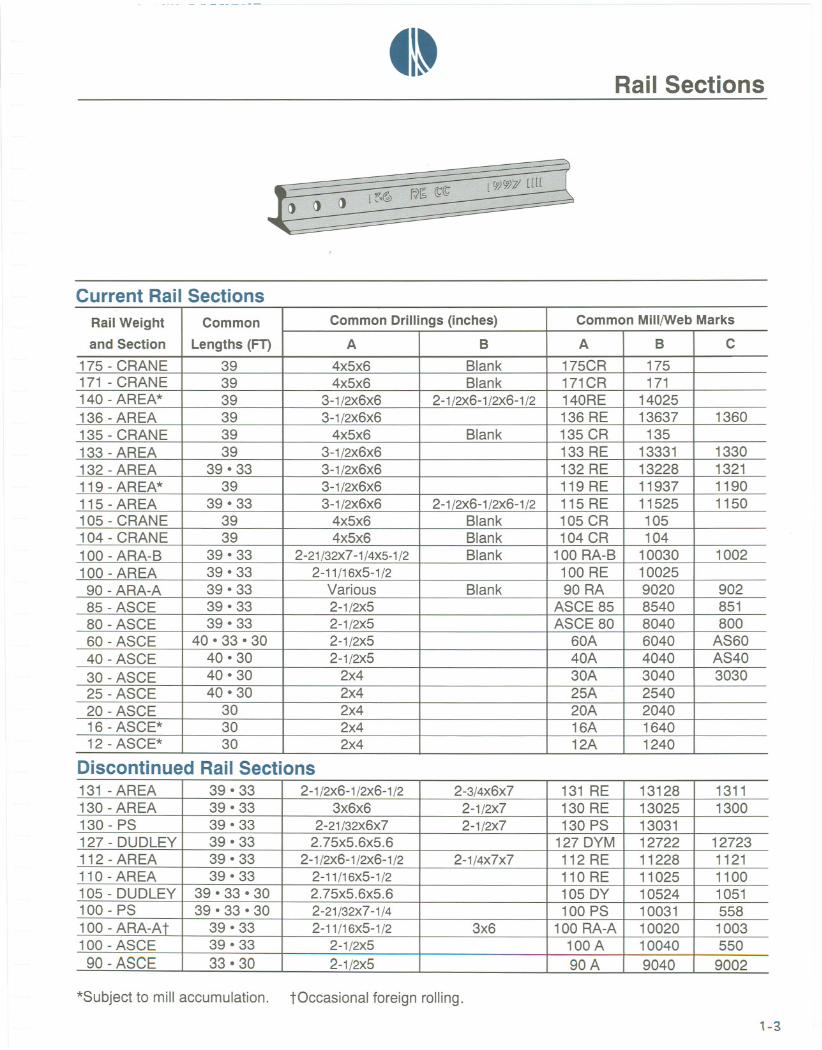
Rail Sections. Tee rail was first manufactured in the United States in 1845. Crane raildid not become available until the turn of the century. Generally, tee rail is used forrailroad application and crane rail for port facilities. Either can be used for a cranerunway system.
In this section, we list dimensions of all Current Rail Sections plus some Discontinued RailSections that are frequently found in older track systems. Our Company files containinformation on practically every rail that was ever produced. Profiles and data sheets ofpopular domestic and foreign rail sections are also included in this chapter of THESOURCEbook.
New Rail. We inventory every type of ASCE, AREA, ARA-A, ARA-B and CR rail sectionthat is presently produced throughout the world. Each piece of new rail in our inventoryis documented by a mill certificate or a test report. Crane rail can be supplied controlcooled, end hardened or heat treated.
Relay Rail. Our inventory of relay rail changes according to availability. We can supplyrails and matching accessories to meet any specification. Normal inventory consists of rail140-lb per yard through 60-lb per yard. All of our relay rail is guaranteed to be straight,uniform in height and drilling and completely suitable for use in any top-grade tracksystem.
Fabrication. Atlantic Track can also weld, bend, cut, drill and punch rail per yourspecifications. In many cases, we have modified standard equipment to suit the needs ofrail-related fabrication. Our technical specialists are at your disposal no matter how largeor small the job.
Note: Brand-to-brand installation is highly recommended on all new rail construction.The raised brand rail web identification should be on the same side for all connected rails.
1-1

_1-Rail Sections
W -Web
D -Depth of HeadF -FishingE -Depth of Base
j4-- HD--+1I I
__n_tIIIIIH
: ~:(~~Ti(nnn J ~ i~- ......B ~--
H-HeightB -BaseHD -HeadL -Elevation
Current Rail Sections
Discontinued Rail Sections
*Subject to mill accumulation. tOccasional foreign rolling. All dimensions are in inches.
1-2
Rail Weightand Section H B HD W D F E L
175 - CRANE 6 6 4-1/4 1-1/2 1-3/4 3-7/64 1-9/64 2-21/32171 - CRANE 6 6 4.3 1-1/4 2 2-3/4 1-1/4 2-5/8140 - AREA* 7 -5/16 6 3 3/4 2-1/16 4-1/16 1-3/16 Varies136 - AREA 7-5/16 6 2-15/16 11/16 1-15/16 4-3/16 1-3/16 3-23/64135 - CRANE 5-3/4 5-3/16 3-7/16 1-1/4 1-7/8 2-13/16 1-1/16 2-15/32133 - AREA 7-1/16 6 3 11/16 1-15/16 3-15/16 1-3/16 3132 - AREA 7-1/8 6 3 21/32 1-3/4 4-3/16 1-3/16 3-3/32119 - AREA* 6-13/16 5-1/2 2-21/32 5/8 1-7/8 3-13/16 1-1/8 2-7/8115 - AREA 6-5/8 5-1/2 2-23/32 5/8 1-11/16 3-13/16 1-1/8 2-7/8105 - CRANE 5-3/16 5-3/16 2-9/16 15/16 1-25/32 2-13/32 1 2-13/64104 - CRANE 5 5 2-1/2 1 1-1/2 2-7/16 1-1/16 2-7/16100 - ARA-B 5-41/64 5-9/64 2-21/32 9/16 1-45/64 2-55/64 1-5/64 2-65/128100 - AREA 6 5-3/8 2-11/16 9/16 1-21/32 3-9/32 1-1/16 Varies
90 - ARA-A 5-5/8 5-1/8 2-9/16 9/16 1-15/32 3-5/32 1 2-37/64
85 - ASCE 5-3/16 5-3/16 2-9/16 9/16 1-35/64 2-3/4 57/64 2-17/6480 - ASCE 5 5 2-1/2 35/64 1-1/2 2-5/8 7/8 2-3/1660-ASCE 4-1/4 4-1/4 2-3/8 31/64 1-7/32 2-17/64 49/64 1-115/12840 - ASCE 3-1/2 3-1/2 1-7/8 25/64 1-1/64 1-55/64 5/8 1-71/12830-ASCE 3-1/8 3-1/8 1-11/16 21/64 7/8 1-23/32 17/32 1-25/64
25 - ASCE 2-3/4 2-3/4 1-1/2 19/64 25/32 1-31/64 31/64 1-29/128
20-ASCE 2-5/8 2-5/8 1-11/32 1/4 23/32 1-15/32 7/16 1-11/6416 - ASCE* 2-3/8 2-3/8 1-11/64 7/32 41/64 1-23/64 3/8 1-1/1612 - ASCE* 2 2 1 3/16 9/16 1-3/32 11/32 57/64
131 - AREA 7-1/8 6 3 21/32 1-3/4 4-3/16 1-3/16 3-1/4
130 - AREA 6-3/4 6 2-15/16 21/32 1-27/32 3-11/16 1-7/32 2-3/4
130 - PS 6-5/8 5-1/2 3 11/16 2 3-13/32 1-7/32 2-3/4127 - DUDLEY 7 6-1/4 3 21/32 1-11/16 4-5/32 1-5/32 Varies
112 - AREA 6-5/8 5-1/2 2-23/32 19/32 1-11/16 3-13/16 1-1/8 2-7/8
110 - AREA 6-1/4 5-1/2 2-25/32 19/32 1-23/32 3-13/32 1-1/8 Varies105 - DUDLEY 6 5-1/2 3 5/8 1-5/8 3-13/32 '=11/'=1') 2-5/8100 - PS 5-11/16 5 2-43/64 9/16 1-13/16 2-25/32 1-3/32 2-31/64
100 - ARA-At 6 5-1/2 2-3/4 9/16 1-9/16 3-3/8 1-1/16 2-3/4100 - ASCE 5-3/4 5-3/4 2-3/4 9/16 1-45/64 3-5/64 1/? 2-1/2
90-ASCE 5-3/8 5-3/8 2-5/8 9/16 1-19/32 2-55/64 59/64 2-23/64
~I~Rail Sections
000l~~ r~~ ~~
Current Rail Sections
Discontinued Rail Sections
*Subject to mill accumulation. tOccasional foreign rolling.
1-3
Rail Weight Common CommonDrillings (inches) Common Mili/WebMarks
and Section Lengths (FT) A B A B C
175 - CRANE 39 4x5x6 Blank 175CR 175171 - CRANE 39 4x5x6 Blank 171CR 171140 - AREA* 39 3-1/2X6x6 2-1 /2x6-1 /2x6-1 /2 140RE 14025136 - AREA 39 3-1/2X6x6 136 RE 13637 1360135 - CRANE 39 4x5x6 Blank 135 CR 135133 - AREA 39 3-1/2X6x6 133 RE 13331 1330132 - AREA 39 . 33 3-1/2X6x6 132 RE 13228 1321119 - AREA* 39 3-1/2X6x6 119 RE 11937 1190115 - AREA 39 . 33 3-1/2X6x6 2-1/2X6-1/2X6-1/2 115 RE 11525 1150105 - CRANE 39 4x5x6 Blank 105 CR 105104 - CRANE 39 4x5x6 Blank 104 CR 104100 - ARA-B 39 . 33 2-21/32X7-1/4XS-1/2 Blank 100 RA-B 10030 1002100 - AREA 39 . 33 2-11/16X5-1/2 100 RE 1002590 - ARA-A 39 . 33 Various Blank 90 RA 9020 90285 - ASCE 39 . 33 2-1/2X5 ASCE 85 8540 85180 - ASCE 39 .33 2-1/2X5 ASCE 80 8040 80060 - ASCE 40 .33 .30 2-1/2X5 60A 6040 AS6040-ASCE 40 . 30 2-1/2X5 40A 4040 AS40
30 - ASCE 40 .30 2x4 30A 3040 303025 - ASCE 40 .30 2x4 25A 254020 - ASCE 30 2x4 20A 204016 - ASCE* 30 2x4 16A 164012 - ASCE* 30 2x4 12A 1240
131 - AREA 39 . 33 2-1/2X6-1/2X6-1/2 2-3/4X6x7 131 RE 13128 1311130 - AREA 39 . 33 3x6x6 2-1/2X7 130 RE 13025 1300130 - PS 39 . 33 2-21/32X6x7 2-1/2X7 130 PS 13031127 - DUDLEY 39 . 33 2.75x5.6x5.6 127 DYM 12722 12723112 - AREA 39 .33 2-1/2X6-1/2X6-1/2 2-1/4X7x7 112 RE 11228 1121110 - AREA 39 .33 2-11/16X5-1/2 110 RE 11025 1100105 - DUDLEY 39 .33 . 30 2.75x5.6x5.6 105 DY 10524 1051100 - PS 39 .33 .30 2-21/32X7-1/4 100 PS 10031 558100 - ARA-At 39 .33 2-11/16X5-1/2 3x6 100 RA-A 10020 1003100 - ASCE 39 .33 2-1/2X5 100A 10040 55090 - ASCE 33 . 30 2-1/2X5 90A 9040 9002

175.lb41-
CRANEShown Actual Size
SpecificationsNominal Weight
Standard Length
Standard Drilling
Joint Bar Length
Joint Bar WeightWith Hardware
Bolt Diameter
See page 7-2for all other dimensions.
175lbs/yd39'0"
4" x 5" x 6"34"
69.4 Ibs/pr86.6 Ibs/pr
11/8"
U2
1-4
6"

171.lb~I~ CRANE
Shown Actual Size
Base6"
SpecificationsNominal Weight
Standard Length
Standard Drilling
Joint Bar Length
Joint Bar WeightWith Hardware
Bolt Diameter
See page 7-2for all other dimensions.
Double
F2
S2
H2
U2
6"
1-5
Hold-Down Devices
171Ibs/yd Standard Single39'0" Hook Bolt 1"
4"x5"x6" Clip Number 171-34" Clamp & Filler F1-
72.1 Ibs/pr WeldedStud S189.3 Ibs/pr
11/8" WeldedHolderWeldedU-Bar

136.lb_It A.R.E.A.
Shown Actual Size
75/16"
SpecificationsNominal Weight
Standard Length
Standard Drilling
Joint Bar Length
Joint Bar WeightWith Hardware
Bolt Diameter
See page 7-2for all other dimensions.
136lbs/yd39'0"
116.7Ibs/pr128.7Ibs/pr
11/8"
HookBolt
Clip NumberClamp & Filler
1"
3%" x 6" x 6"
36"
1-6

135.lb_I~ CRANE
Shown Actual Size
Head37/16"
53/4"
Base53/16"
1-7
Specifications Hold-Down Devices
Nominal Weight 135 Ibs/yd Standard Single Double
Standard Length 39'0" Hook Bolt 1"
Standard Drilling 4" x 5" x 6" Clip Number 62
Joint Bar Length 34" Clamp &Filler F1 F2
Joint Bar Weight 57.8Ibs/pr Welded Stud S1 S2With Hardware 74.2 Ibs/pr Heavy Duty Single Double
Bolt Diameter 11fs" Welded Holder H1 H2See page 7-2 WeldedU-Bar U1 U2for all other dimensions.

133.lb _I~ A.R.E.A.
71116"
F2S2
H2
1-8
Specifications Hold-Down Devices
Nominal Weight 133 Ibs/yd
Standard Length 39'0" Hook Bolt 1"
Standard Drilling 3%" x 6" x 6" Clip Number 62
Joint Bar Length 36" Clamp & Filler F1
Joint Bar Weight 116.7Ibs/pr Welded Stud S1With Hardware 128.7Ibs/pr
Bolt Diameter 1%"or1" Welded Holder H1See page 7-2 Welded U-Barfor all other dimensions.

132.lb~I~ A.R.E.A.
Actual Size
SpecificationsNominal Weight
Standard Length
Standard Drilling
Joint Bar Length
Joint Bar WeightWith Hardware
BoltDiameterSee page 7-2for all other dimensions.
Hold-Down Devices132lbs/yd
39'0"
31/2" x 6" x 6"
36"
Hook Bolt
Clip Number
Clamp & FillerWelded Stud
1"
113.1 Ibs/pr125.7Ibs/pr
1Vs"or 1" Welded Holder
Welded U-Bar
H1 H2
71fa"
1-9

115-lb_1-
A.R.E.A.Shown
65/8"
F2
S2
H2
1-10
Specifications Hold-Down Devices
Nominal Weight 115 Ibs/yd
Standard Length 39'0" Hook Bolt 1"
Standard Drilling 31/2"x 6" x 6" Clip Numbers 62
Joint Bar Length 36" Clamp & Filler F1
Joint Bar Weight 93.8 Ibs/pr Welded Stud S1With Hardware 105.8 Ibs/pr
Bolt Diameter 1" Welded Holder H1See page 7-2 Welded U-Barfor all other dimensions.

105.lbtl~ CRANE
SpecificationsNominal Weight
Standard Length
Standard Drilling
Joint Bar Length
Joint Bar WeightWith Hardware
Bolt Diameter
See page 7-2for all other dimensions.
105lbs/yd39'0"
4" x 5" x 6"
34"
51.6Ibs/pr61.0 Ibs/pr
Shown Actual Size
Head
Base58/16"
7/S"
Hold-Down Devices
Standard ......
Hook Bolt
Clip Number
Clamp & FillerWelded Stud
bI~f'!~YD~~y
Welded Holder
Welded U-Bar
53f16"
Single.1"
Double
62F1S1
SingleH1U1
F2S2
DOubleH2U2
1-11

104.lb~I~
CRANE
5"
1"
Specifications
Nominal Weight
Standard Length
Standard Drilling
Joint Bar Length
Joint Bar WeightWith Hardware
Bolt Diameter
See page 7-2for all other dimensions.
104lbs/yd39'0"
4" x 5" x 6"
34"
60.2 Ibs/pr71 .4 Ibs/pr
U1 U2
1-12

100.lb_I~ A.R.A..A
Shown Actual Size
Head
-------
6"
Base5%"
SpecificationsNominal Weight
Standard Length
Standard Drilling
Joint Bar Length
Joint Bar WeightWith Hardware
Bolt Diameter
See page 7-2for all other dimensions.
100lbs/yd39'0"
Hold-Down DevicesStandardHookBolt
Clip Numbers
Clamp & FillerWelded Stud
li"I~a\l~iipu1YWelded Holder
Welded U-Bar
Single Double
1"
211;;6" X 5112"
24"
1"
103.62F1
S1
51091eH1U1
F2
S2
D~ouCbje
H2
U2
62.7 Ibs/pr70.7Ibs/pr
1-13

100-lb ~I~ A.R.A.-BShown Actual Size
541j64"
Specifications
Nominal Weight
Standard Length
Standard Drilling
Joint Bar Lengths
Joint Bar WeightsWith Hardware
Bolt Diameter
See page 7-2for all other dimensions.
1"
100lbs/yd39'0"
(Stocked Blank)26".36"
58.5Ibs' 81.0 Ibs/pr66.5 Ibs. 93.0 Ibs/pr
U1 U2
1-14
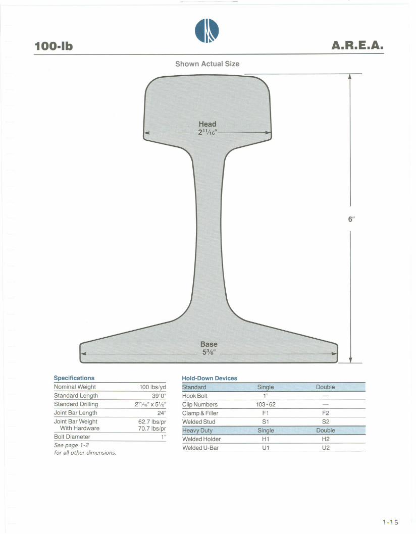
100-lbtl~ A.R.E.A.
Shown Actual Size
Hold-DownDevicesStandardHookBoltClip Numbers
Clamp & FillerWelded Stud
l~av~~Uty,Welded Holder
Welded U-Bar
SpecificationsNominal Weight
Standard Length
Standard Drilling
Joint Bar Length
Joint Bar WeightWith Hardware
Bolt Diameter
See page 1-2for all other dimensions.
100lbs/yd39'0"
211/16" X 51/2"
24"
62.7 Ibs/pr70.7Ibs/pr
1"
6"
Base53/8"
Single Double1"
103.62
F1
S1
S.I~gleH1
U1
F2
S2
. Double ..H2U2
1-15

90-lb_I~ A.R.A.-A
Shown Actual Size
55/8"
SpecificationsNominal Weight
Standard Length
Standard Drilling
Joint Bar Length
Joint Bar WeightWith Hardware
Bolt Diameter
See page 7-2for all other dimensions.
90 Ibs/yd39'0" Hook Bolt
Clip Numbers
Clamp & FillerWelded Stud
7/8"
62.4 Ibs/pr70.0 Ibs/pr
106.62
F1
S1
F2
S2
(Stocked Blank)24"
1" Welded Holder
Welded U-Bar U1 U2
1-16

85.lb~I~ A.S.C.E.
Shown Actual Size
53/16"
Base53116"
SpecificationsNominal Weight
Standard Length
Standard Drilling
Joint Bar Length
Joint Bar WeightWith Hardware
Bolt Diameter
See page 7-2for all other dimensions.
2112"X5"
24"
Hold-Down Devices
~tandardHookBolt
Clip Numbers
Clamp & FillerWelded Stud
f:lea,yyputyWelded Holder
Welded U-Bar
Single7/8"
Double85 Ibs/yd39'0"
49.6Ibs/pr55.0 Ibs/pr
7/8"
103.106
F1
S1
Single
F2
S2
Double
U1 U2
1-17

80-lb 41~ A.S.C.E.Shown Actual Size
5"
SpecificationsNominal Weight
Standard Length
Standard Drilling
Joint Bar Length
Joint Bar WeightWith Hardware
Bolt Diameter
See page 7-2for all other dimensions.
Hold-Down Devices
80 Ibs/yd39'0"
21/2"X 5"24"
HookBolt
Clip Numbers
Clamp & FillerWelded Stud
7/8"
46.0 Ibs/pr51 .4 Ibs/pr
103.106
F1
S1
F2
S2
7/8" Welded Holder
Welded U-Bar U1 U2
1-18

60.lb41~ A.S.C.E.
Shown Actual Size
Hold-Down Devices
Standard. . .
Hook Bolt
Clip Numbers
Clamp &FillerWelded Stud
Heavy DutyWelded Holder
Welded U-Bar
ad2318"
Base41f4"
Specifications
Nominal Weight
Standard LengthsStandard Drilling
Joint Bar Lengths
Joint Bar WeightsWith Hardware
Bolt Diameter
See page 7-2for all other dimensions.
60 Ibs/yd39'0" .33'0"
21/2" X5"
20". 24"27.2 Ibs. 32.5 Ibs/pr30.1 Ibs. 35.4 Ibs/pr
3/4"
Sirlgle -3/4"
103.106
F1S1
Single
U1
41f4"
Double
F2
S2
Double
U2
1-19

40.lbtit A.S.C.E.
Shown Actual Size
Specifications
Nominal Weight
Standard Length
Standard Drilling
Joint Bar Length
Joint Bar WeightWith Hardware
Bolt Diameter
See page 7-2for all other dimensions.
1-20
31f2"
F2
S2
Hold-DownDevices- ..........................
40 Ibs/yd30'0" Hook Bolt 3/4"-
2112"X 5" Clip Numbers 103.114.120
20" Clamp & Filler F1-15.2Ibs/pr Welded Stud S118.2 Ibs/pr
3/4" Welded Holder
Welded U-Bar

30-lb tl~ A.S.C.E.Shown Actual Size
SpecificationsNominal Weight
Standard Length
Standard Drilling
Joint Bar Length
Joint Bar WeightWith Hardware
Bolt Diameter
See page 7-2for all other dimensions.
3118"
Hold-Down Devices
30 Ibs/yd30'0"
2"x4"16%"
7.0Ibs/pr8.5 Ibs/pr
F2
5/8"
Welded U-Bar
1-21

25.lb tl~ A.S.C.E.Shown Actual Size
23/4"
F2
1-22
Specifications Hold-Down Devices
Nominal Weight 25 Ibs/yd
Standard Length 30'0" Hook Bolt V2"
Standard Drilling 2"x4" Clip Number 114
Joint Bar Length 16%" Clamp &Filler F1
Joint Bar Weight 5.7 Ibs/pr Welded Stud S1With Hardware 6.6 Ibs/pr
Bolt Diameter 112" Welded HolderSee page 1-2 Welded U-Barfor all other dimensions.
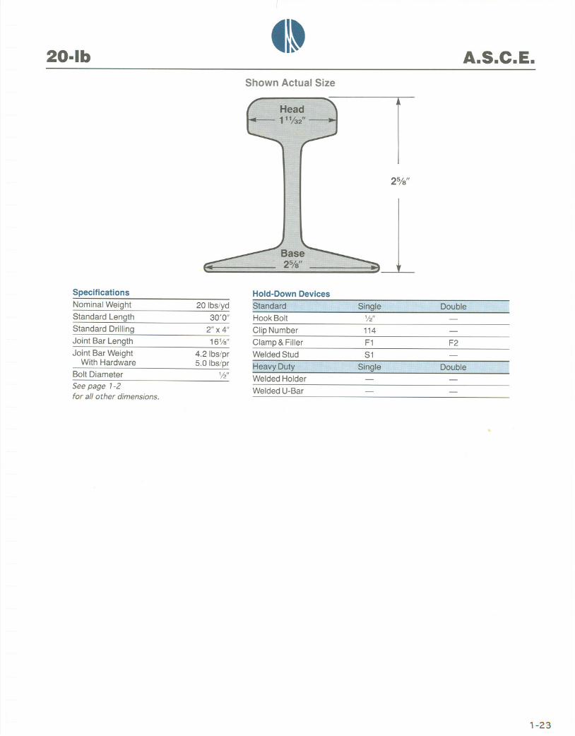
20-lb ~I~ A.S.C.E.Shown Actual Size
SpecificationsNominal Weight
Standard Length
Standard Drilling
Joint Bar Length
Joint Bar WeightWith Hardware
Bolt Diameter
See page 7-2for all other dimensions.
25/8"
F2
1-23
Hold-Down Devices
20 Ibs/yd30'0" Hook Bolt-
2"x4" Clip Number 114-16%" Clamp & Filler F1
4.2 Ibs/pr Welded Stud S15.0 Ibs/pr
1/2" . 'v'UvU I IV"'-
Welded U-Bar

16.lb* ~I~ A.S.C.E.Shown Actual Size
SpecificationsNominal Weight
Standard Length
Standard Drilling
Joint Bar Length
Joint Bar WeightWith Hardware
Bolt Diameter
See page 7-2for all other dimensions.
'-24
23/8"
* Subject to mill accumulation.
Hold-Down Devices-16 Ibs/yd
30'0" Hook Bolt 112"
2"x4" Clip Number16%" Clamp & Filler F1
3.6Ibs/pr Welded Stud S14.4 Ibs/pr
1/2" Welded Holder
Welded U-Bar

12-lb* ~I~ A.S.C.E.Shown Actual Size
2"
,1SpecificationsNominal Weight
Standard Length
Standard Drilling
Joint Bar Length
Joint Bar WeightWith Hardware
Bolt Diameter
See page 7-2for all other dimensions.
Hold-DownDevices
12lbs/yd30'0"
2"x4" Clip Number
Clamp & FillerWelded Stud
F1S1
16%"
2.9 Ibs/pr3.7 Ibs/pr
1/2"
Welded U-Bar
* Subject to mill accumulation.
1-25

41-Rai I Sections
Not
Height
DIN Profile Rail*
*Special order. Quantity will determine availability of grades 70, 80 or 90.NOTE: For U.S/Metric conversion tables see page 6-3
1-26
DIN Hei Jht Base Head Web Weight
Number mm in mm in mm in mm in kg/m Ibs/yd
A 120 105 4.13 220 8.66 120 4.72 72 2.83 101 .30 204.21
A 100 95 3.74 200 7.87 100 3.94 60 2.36 75.20 151.60
A 75 85 3.35 200 7.87 75 2.95 45 1.77 56.60 114.10
A65 75 2.95 175 6.89 65 2.56 38 1.50 43.50 87.69
A55 65 2.56 150 5.91 55 2.17 31 1.22 32.00 64.51
A45 55 2.17 125 4.92 45 1.77 24 .94 22.20 44.75

tl-Rail Sections
Multi-purposePunch Multi-spindled Drill
Fabrication
Rail Bending
Straight CutsMitre Cuts
Special Cuts
Drilling
Punching
1-27

41~u[g]~ ~@[l:D~~~@@@~
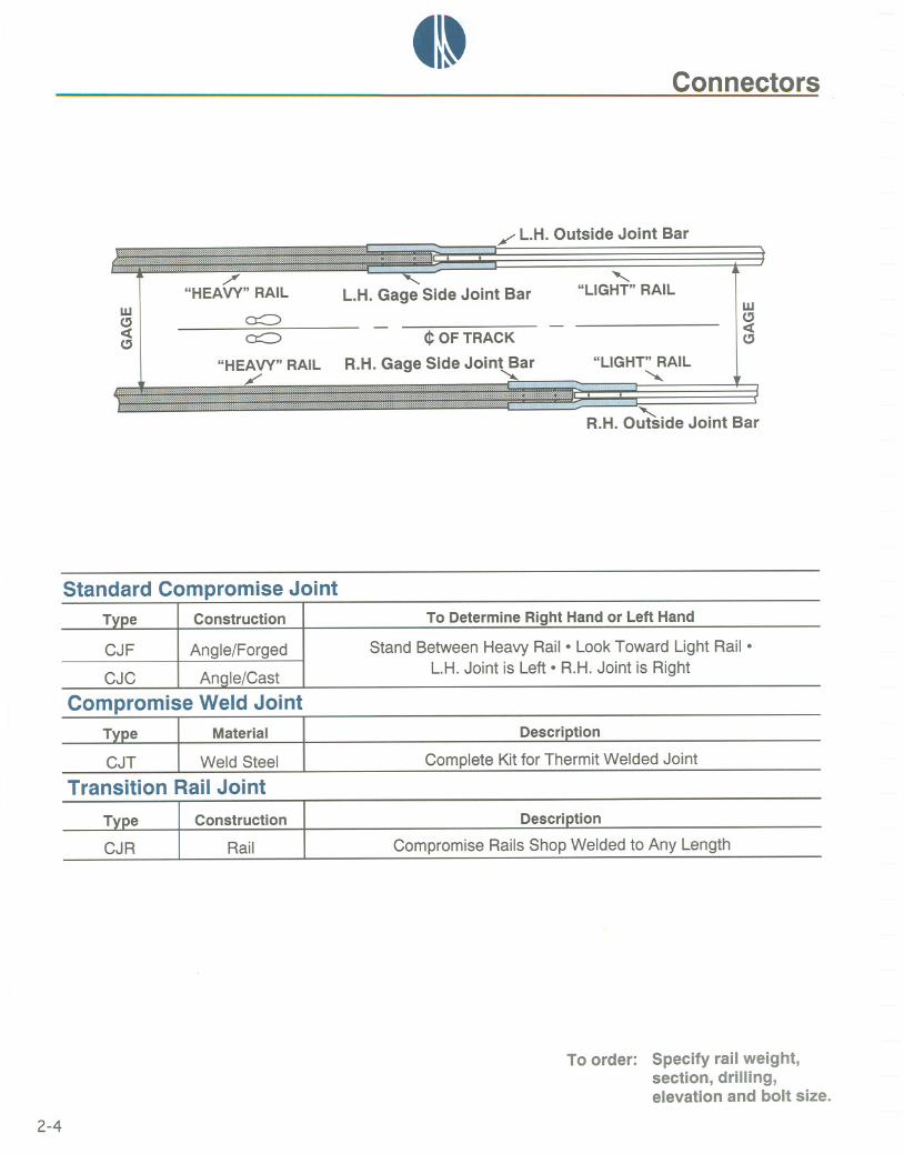
Connectors. Joint bars and bolts are used to fasten rails together. Tie plates and spikesattach rails and ties to produce track. Compromise bars join rails of unequal size.
Joint Bars. There are three types of standard joint bars which are currently in service.Our charts show the type of bar which is supplied for each rail section. An additionalchart shows standard rail drilling and bar punching. The illustrations are intended toshow typical shapes exclusive of size.
Six-hole joint bars are provided for all crane rail and new tee rail sections over lOO-lb peryard. New rail100-lb per yard and less is furnished with four-hole joint bars. All relay railis supplied with matching joint bars.
Compromise Joints. Heat-treated compromise joints are used to connect and align railsof unequal size. A standard bar is re-formed by a custom forging process in both thevertical and horizontal planes so that the gage and running surfaces of the joined rails arein true alignment.
Atlantic Track can also supply compromise weld joint kits or shop-fabricated transitionrail joints as suitable alternates to the standard joint.
Tie Plates. Tie plates fasten the rail to the tie and maintain gage and alignment of railsin track. New double shoulder tie plates are available for 5-1/2" and 6" base rail and aremanufactured according to AREA specifications. Used double shoulder tie plates can besupplied to fit most rail bases. New single shoulder tie plates are no longer available, butthey can be furnished as used and will fit any rail section.
Bolts. Crane rail bolts are medium carbon, heat treated per ASTM specification A-325and are shipped complete with heavy hex nuts and lockwashers. Tee rail requiresstandard button-head oval-neck track bolts with heavy square or hex nuts. Lockwashersare furnished on request.
Spikes. Track spikes are produced from hot rolled steel bars and are shipped in 200-lbkegs. Atlantic Track also maintains a complete inventory of screw spikes, drive spikesand boat spikes.
2-1

_I~Connectors
Splice Full Toe
For Illustration Only
Short Toe
Joint Bars
2-2
Short Toe Bar
order: Specify rail weight,section, drilling,elevation and bolt size.
Rail Type Splice Full Toe Short Toe
Crane Rail175-lb Crane
to 105-lb Crane104-lb Crane -
85-lb ASCE
Tee Rail60-lb ASCE to 70-lb ASCE
140-lb AREA
to 12-lb ASCE 1OO-IbARA-Bto 1OO-IbAREA
90-lb ARA-A1OO-IbARA-A

~I~Connectors
c B A I-F E DA-wA-1
E
Rail Drilling Bar Punching
For Illustration Only
Joint Bars
*These dimensions to be omitted for 4-hole bars.
To order: Specify rail weight,section, drilling,elevation and bolt size.
2-3
- '" c -"'-
0 0 6
Crane 140AREAto 100AREAto 85 ASCE to 30 ASCE toStandard Rail 115AREA 100ARA-A 100ARA-B 90 ARA-A 40 ASCE 12 ASCE
Rail Drillings
A 4" 3-1/2" 2-11/16" Rail Rail 2-1/2" 2"
B 5" 6" 5-1/2" Stocked Stocked 5" 4"
C* 6" 6" 5-1/2" Blank Blank - -
Bar Punchings
D 7-15/16" 7-1/8" 5-1/2" - - 5-1/8" 4-1/8"
E 5" 6" 5-1/2" - - 5" 4"
F* 6" 6" 5-1/2" - - - -
tl-Connectors
/' L.H. Outside Joint Bar
wCJ~CJ
/'"HEAVY" RAIL
0:::::::>0:::::::>
L.H. Gage Side Joint Bar"-
"LIGHT" RAIL
"HEAVY" RAIL/'
<!:OF TRACK
R.H. Gage Side Joint Bar
wCJ~CJ
"LIGHT" RAIL""
R.H. O~ide Joint Bar
Standard Compromise Joint
Compromise Weld JointT e Material
CJT Weld Steel
Transition Rail Joint
Description
Complete Kit for Thermit Welded Joint
Rail
Description
Compromise Rails Shop Welded to Any Length
~CJR
Construction
To order: Specify rail weight,section, drilling,elevation and bolt size.
2-4
Type Construction To Determine Right Hand or Left Hand
CJF Angle/Forged Stand Between Heavy Rail. Look Toward Light Rail.
CJC Angle/Cast L.H. Joint is Left. R.H. Joint is Right

~I~Connectors
Single Shoulder Double Shoulder
AREA Tie Plates
*Oetailed drawings available. Blue print indicates manufactured as of 1997.
Industrial Tie Plates
All dimensions are in inches.
2-5
Type Shoulders Holes AREA* Size Rail Base
OS3 2 4 to 8 Plan 3 7-3/4x12 5-1/2
OS7 2 4 to 8 Plan 7 7-3/4x13 5-1/2
OS8 2 4 to 8 Plan 8 7-3/4x14 5-1/2
OS11 2 4 to 8 Plan 11 7-3/4x13 6
OS12 2 4 to 8 Plan 12 7-3/4x14 6
OS13 2 4 to 8 Plan 13 7-3/4x14-3/4 6
Type Shoulder(s) Holes Sketch Size Rail Base
SSI 1 Minimum3 Yes Varies Any
OSI 2 4 to 8 Yes 7-1/2x11 5-1/2

_ItConnectors
~
Diameter
Thread
Length
Crane Rail Bolts
Manufactured per ASTM A325 complete with heavy hex nuts and 3/8" lockwashers.
2-6
Rail Weight&Section Diameter Length Thread
175-lb CRANE 1-1/8" 6-1/4" 2"
171-lb CRANE 1-1/8" 6-1/4" 2"
135-lb CRANE 1-1/8" 5-1/2" 2"
105-lb CRANE 7/8" 5" 1-3/4"
104-lb CRANE 1" 5-1/4" 1-3/4"

_I~Connectors
Diameter
Thread
Length
Tee Rail Bolts
Manufactured to AREA specifications. *Average per 200-lb keg.
2-7
Rail Weight Diameter Length Thread Pieces*
140 - 136 1-1/8" 6" 2-1/4" 105
133 - 132 1-1/8" or 1" 6" 2-1/4" 105
119-115 1" 5-1/2" 2-1/4" 111
100 1" 5-1/2" 2-1/4" 111
90 1" 5" 2-1/4" 118
85 - 80 7/8" 4-1/2" 2" 163
70 3/4" 4" 1-3/4" 254
60 3/4" 3-1/2" 1-3/4" 272
40 3/4" 3" 1-3/4" 293
30 5/8" 2-1/2" 1-1/4" 520
25 1/2" 2-1/2" 1-1/8" 858
20 - 16 - 12 1/2" 2" 1-1/8" 990

titConnectors
Thickness
~
Taper
Length
Track Spikes
*Manufactured to AREA and ASTM specifications.tNote: 1OO-IbAREA may require a 9/16" spike.
**Average per 200-lb keg.
2-8
Rail Weight Thickness Length Taper Pieces/Keg**
140 to 100t 5/8"* 6" 1-1/4" 244
90 to 80 9/16"* 5-1/2" 1-1/8" 322
70 to 40 1/2" 4-1/2" 7/8" 505
30 to 12 3/8" 3-1/2" 5/8" 1135


tl~u[i=(]~~(Q)[lJJ~~~[Q)@@~
Trackwork. For over seventy years, we have been supplying standard and specialtrackwork that conforms to both the specification and the delivery schedule.
New trackwork is required for transit systems and mainline use on Class I railroads. Forall other applications, relay material can be installed without sacrificing safety ordurability.
Reconditioned trackwork is created from surplus material that was originallymanufactured according to AREA or Class I railroad specifications. Atlantic Trackcombines these basic elements with new parts to produce the finest re-manufacturedtrackwork that is available today.
Listed below are the four major turnout components. In addition, the table on page 3-6classifies standard turnouts according to Industrial, AREA, Pavement and Narrow Gagedesigns. Each component is then broken down by type. Special Trackwork, OtherTrackwork and Accessories complete this section of the THE SOURCEbook.
Turnout Components
I FrogII Switch
III Guard Rails
IV Switch Stand and Target
Special TrackworkAssembled Turnouts
CrossingsCrossovers
Tongue Switches
Turnouts Include
Switch Plates and BracesSlide and Heel PlatesHook Twin Tie PlatesHeel Blocks
Gage Plate(s)Necessary Rods
Other Trackwork .
TransitMineTunnel
When SpecifiedStock RailsClosure Rails*Turnout Rails
AccessoriesSwitch Point DerailSwitch Point GuardSwitch Point LockSwitch Point Protector
*Seepage6-7for lengths.
3-1

tl~Trackwork
Restoration
3-2

~I~Trackwork
Restoration
3-3

tItTrackwork
SK-1
SK-3
SK-2
5t d dL t
Most Trackwork Can be Supplied New or Used
3-4
Sketch Description Comments
SK-1 Standard Turnout Stand Between Points. Look at Frog. Left Hand Goes Left.Right Hand goes Right. Our Logo is a Left-Hand Turnout.
SK-2 Equilateral Turnout Sometimes Called Diamond Turnout
SK-3 Three-way Turnout Left, Right or Center Track Can be Used

_I~Trackwork
SK-4 SK-6
SK-5 SK-7
Standard Layouts
Most Trackwork Can be Supplied New or Used
3-5
Sketch Description Comments
SK-4 Single Crossover Hand of Turnouts Determine Hand of Crossover
SK-5 Double Crossover Uses Four Turnouts (2LH, 2RH) Plus Crossing
SK-6 90° Crossing AREA 701,702,746,771
SK-7 Diamond Crossing AREA 701 to 706,708,710,746 to 748,755,757,761,768,769,771 to 775

~I~Trackwork
POINT OFSWITCH
GAGE
ACTUAL LEAD - 'I. POINTOF FROGrSTAGGERi
SWITCHPOINTGUARDRAILI
SWITCH POINTS- HEEL BLOCKS
STRAIGHT STOCK RAIL STRAIGHT TURNOUT RAIL
GUARD RAILS
--r ----------
__L_-CURVED CLOSURE RAIL
STRAIGHT CLOSURE RAIL -----------
CURVED TURNOUT RAIL
------------
Standard Turnout with Straight Split Switch
Most Trackwork Can be Supplied New or Used
*See page6-7for closurerail lengths.
3-6
Standard Turnouts*tn
Design/Service Frog I Switch I Guard Rails I Switch Stand
Industrial FBR SI GTR, GHF A51, A44, A1222
Heavy Industrial FMSG SI NONE A51, A44
AREA (1) FMSG SA NONE A51, A44
AREA (2) FMI SA GTR A51, A44
Pavement FSM TSB, TSSMGTR, GHF, GSM I A96
DTB,DTSM
Narrow Gage I FWP .ui SI I GMC, GWP I A1222, A1217

_I~Trackwork
"------
':1~~~~~~'~~i~i~:wm
For Illustration Only
Type
FWP
FBR
AREA
None
Construction Service
FSM 671
Welded Plate
Bolted RigidRail Construction
ManganeseSelf-guarded Casting
CombinationRail and Manganese
Casting
Manganese Heavy Industrial in PavementFlat Top Casting Slow Mainline, MinefTunnel
Most Trackwork Can be Supplied New or Used
MinefTunnel Application
Industrial322,323,324
FMI
640,641
612 to 615617 to 620622 to 625
Heavy IndustrialRailroad Yard Track
FMSG*
Heavy and/or High-speedMainline Traffic
*Shown above
3-7

_I~Trackwork
0 0 0 DI
D
D DIII~1 ID D
For Illustration Only
Most Trackwork Can Be Supplied New Or Used
Note: Common length shown. All lengths are available.
3-8
Split Switches 161-6" Long
Type I Design/ Switch Heel GageSlide I Rail I Plain I Heel I Hook TwinService Rods Blocks Plate Plates Braces Plates Plates Tie Plates
SI Industrial 2 2 1 12 12
SA AREA 2 2 1 14 36

~I~Trackwork
0 0 0 01
0
0 olll~1 100 0 0
For Illustration Only
Most Trackwork Can Be Supplied New Or UsedNote: Common length shown. All lengths are available.
3-9
Split Switches 111.0" Long
TypeI Heel I GageBlocks Plate
SI Industrial 1SA AREA 1
Slide I Rail I PlainHeel Hook Twin
Plates Braces Plates Plates Tie Plates
8 2 4 8
10 - 4 I 20

_I~Trackwork
0 r ,I I
0 0 0
m
0r-- --,I I
0 ,---,I ,
::::::::t:: ode::: ..:-:-:-: ::::;;':;;;;.i-if:f:;;;::;;:.,,#:#;;
For Illustration Only
Guard Rails
Type
GMC
GWP
GTR
GHF*
GSM
Design Construction
AMC Tee Rail, Separator Blocks
ATT One Piece. Welded Plate
AREA 504 Tee Rail, Separator Blocks, Hook Twin Tie Plates
Hook Flanae I One Piece. Rail, Tie Plates, Foot Guards
One Piece Manganese I Integral Plates and Braces
Most Trackwork Can be Supplied New or Used*Shown above
3-10
41~Trackwork
I-
For Illustration Only
Service
Railroad I Industrial
Rails 60-lbs. and
Over I Under
xXXXX
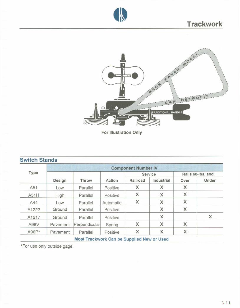
Parallel I Positive I ~ I ~Most Trackwork Can be Supplied New or Used
*For use only outside gage.
X
X
X
X
X
X
X
X
A96P* Pavement
X
X
3-11
IDesign I Throw I Action
A51 Low Parallel Positive
A51H Hiah Parallel Positive
A44 Low Parallel Automatic
A1222 I Ground Parallel Positive
A1217 I Ground Parallel Positive
A96V I Pavement IPerpendicularl Spring
tl-Trackwork
For Illustration Only
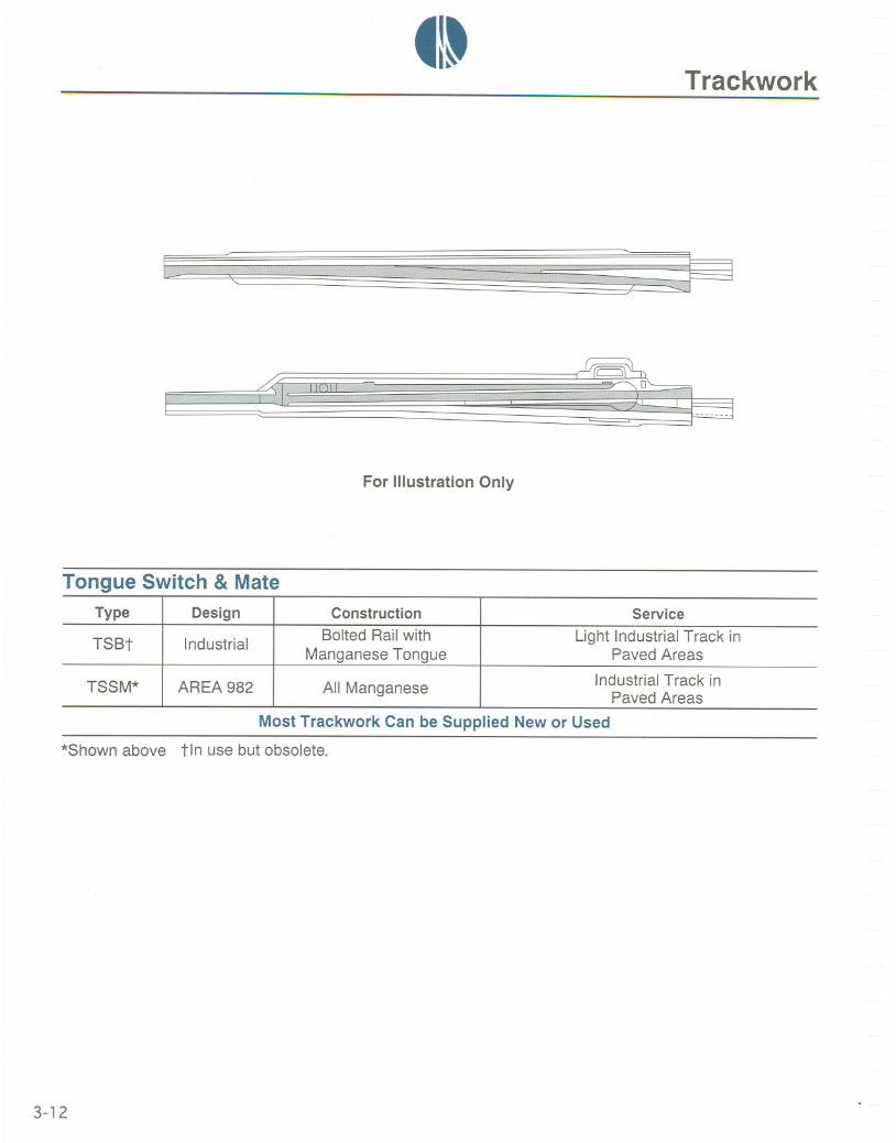
Tongue Switch & Mate
MostTrackwork Can be Supplied New or Used
*Shownabove tin usebutobsolete.
3-12
Type Design Construction Service
TSBt Industrial BoltedRailwith LightIndustrialTrack inManganese Tongue Paved Areas
TSSM* AREA982 AllManganeseIndustrialTrack in
Paved Areas

~I~Trackwork
For Illustration Only
Double Tongue Switch
Most Trackwork Can be Supplied New or Used
*Shown above tin use but obsolete.
3-13
Type Design Construction Service
DTBt Industrial Bolted Rail with Two Light Industrial Track inManganese Tongues Paved Areas
DTSM* AREA 987 All ManganeseIndustrial Track in
Paved Areas

~I~Trackwork
Crossings
MostTrackworkCan be Supplied New or Used*Shown above
3-14
Type Construction Description Service
CWP Welded Plate Industrial Rail Up to 100-lbs./yd. Light
CBR Bolted Rail One, Two*, or Three-Rail Design Medium
CMI Manganese Insert Cast Frogs at Each Intersection Heavy
CSM Solid Manganese One-Piece Design Down to 25° Heavy
~I~Trackwork
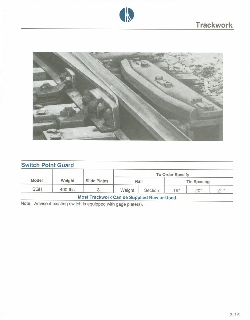
Switch Poi nt Guard
To Order SDeci
Model Weight Slide Plates Rail
21"SGH I 400-lbs. ~ 3 I Weight I Section I 19"
Most Trackwork Can be Supplied New or UsedNote: Advise if existing switch is equipped with gage plate(s).
3-15

_I~Trackwork
For Illustration Only
Transit
Transit Trackworkis AlwaysNew
*Detailedproductliteratureavailableuponrequest.
3-16
Product* Material Description
Coverboard Fiberglass Pultruded Coverboard, Molded Brackets
Insulator Fiberglass Molded per Specification
Shims Fiberglass 1/16",1/8",3/16",1/4",5/16",3/8"
Power Rail Steel/Aluminum Steel Rail, Aluminum Extrusion
Grating Fiberglass Pultruded, High Strength, Light Weight, Non-Conductive
Special Trackwork Steel AREA or Transit Authority Specification

tl~Trackwork
Mine and Tunnel
Most Trackwork Can be Supplied New or Used
3-17
Item Type Specify Comments
Frog FWP, FSM Rail Weight, Number Welded Plate from Stock
Switch SI Rail Weight, Length Standard or Heavy Duty
Guard Rail GMC, GWP Rail Weight, Length Supplied when Required
Switch Stand A1222, A1217 Rail Weight Solid or Spring Connecting Rod
Crossing CWP Rail Weight, Angle Single Crossing, Double Crossover
Turnout Narrow Gage Gaqe, Plate, Ties Panel, Pre-fab, Easy Ship

_ItTrackwork
Switch Point Accessories
No.2 or Back Rod
Switch Rods and Clips
MostTrackworkCan be Supplied Newor Used
*See page 3-20
3-18
To Order SpecifyItem Holes Rod Type* Left or Right Insulated or
Size SDacina Thickness CliD Hand Non-Insulated
Switch Rod X X X X X
Side Jaw Clip X X X X
Transit Clip X X X X
Rocker Clip X X X

41~Trackwork
Switch Point Accessories
Model CRA
Model CRM
Model CRS
Model CRO
~Model CRSE
Connecting Rods
Most Trackwork Can be Supplied New or Used*Not illustrated
3-19
Model Switch Stand Description StandardLengths
CRN* A51 , A51 H Non-Adjustable 3' 11/2",3' 6", 4' 0", 5' 0", 5' 4",6' 0",6' 6"
CRA A51, A51H Single-Adjustable 3' 11/2",3' 6", 4' 0", 5' 0",5' 4",6' 0", 6' 6"
CRM A44 Triple-Adjustable 3' 3",3' 6",4' 0",5' 6",6' 0"
CRO All Models Single-Adjustable 3' 3", 3' 6", 4' 0",5' 0", 5' 4",6' 0", 6' 6"
CRS A1222 Open Spring 3' 101/2"
CRSE A1222, A1217 Enclosed Spring 2' 51/2"

tl~Switch Point Accessories
Trackwork
Side Jaw Clip . Transit Clip. Side Jaw Clip
SC 13-lbs. Specify
Left or Right Hand, Non-Adjustable
AC 20-lbs. Specify TC 9-lbs. Specify
Left or Right Hand Left or Right Hand, Lugs on Rod
Rocker Clip . Lock. Protector
RC SpecifyVaries
No Hand, Vertical Rod Only, Cast
SP Specify SL 10-lbs. All12-lbs.
Manganese, Reversible Customer-Supplied Padlock
*Unless otherwise noted, all clips are forged steel, adjustable and for horizontal rods.order: Dace 8
3-20

41~
~lit Switch Parts
Trackwork
Adjustable Brace . Heel Block
Model/Description.~~ ~ ~~~ ~ ,,~~ ~,,<~" ,-, '
AB-1/Requires Milled Pocket
. Rigid Brace
HB-1/Specify Holes Required
Slide Plate . Heel Plate
'I
Model/Description
SPLJHolds Stock Rail in Position
rJlodel/Description;
RB-2/Non-Adjustable, 3/8" or 1/2"
. Hook Twin Tie Plate
.",,
Model/Description
HTP/For Switches or Frogs
Model/Description
HPUFits Under Heel of Switch
Turnout Plate . Gage Plate
TPLJFor Use Behind Heel of Switch
- -GPUMaintains Gage at Point of Switch, Insulated* or Non-Insulated
*lIIustrated3-21

~I~Trackwork
For Illustration Only
Switch Point Derail 111-0" Long
Most Trackwork Can Be Supplied New Or Used
*Shown above
3-22
Switch Heel Gage Combine Rail Plain Heel Hook Twin
Type Design Rod Block Plate Plates Braces Plates Plates Tie Plates
SOl Industrial 1 1 1 2 3 3 2 4
SOA AREA 213* 1 1 1 3 4 3 2 10
~I~Trackwork
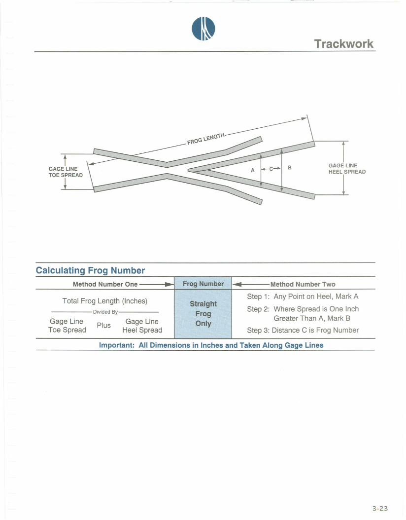
IGAGE LINEHEEL SPREAD
Calculating Frog Number
Important: All Dimensions in Inches and Taken Along Gage Lines
3-23
Method NumberOne -Frqg. Nt.lmbr. ... MethodNumberTwo-
.,:W
Step 1: Any Point on Heel, MarkATotal Frog Length (Inches) Straight
DividedBy FrogStep 2: Where Spread is One Inch
Gage Line Gage Line nl,Greater Than A, Mark B
Plus :w
Toe Spread Heel Spread Step 3: Distance C is Frog Number

_I~THE SOURCEbook
3-24
Phone Numbers
Alabama 1-800-631-1274 Kentucky 1-800-441-8207 North Dakota 1-800-323-6256Alaska 1-800-323-6256 Louisiana 1-800-631-1274 Ohio 1-800-441-8207Arizona 1-800-323-6256 Maine 1-800-631-1274 Oklahoma 1-800-323-6256Arkansas 1-800-323-6256 Maryland (East) 1-800-631-1274 Oregon 1-888-288-7245Asia 1-973-748-5885 Maryland (West) 1-800-441-8207 Pennsylvania (East) 1-800-631-1274California 1-888-288-7245 Massachusetts 1-800-631-1274 Pennsylvania (West) 1-800-441-8207Colorado 1-800-323-6256 Michigan 1-800-323-6256 Rhode Island 1-800-631-1274Connecticut 1-800-631-1274 Minnesota 1-800-323-6256 South Carolina 1-800-631-1274Delaware 1-800-631-1274 Mississippi 1-800-631-1274 South Dakota 1-800-323-6256District of Columbia 1-800-631-1274 Missouri 1-800-323-6256 Tennessee 1-800-631-1274
Europe 1-973-748-5885 Montana 1-800-323-6256 Texas 1-800-323-6256Florida 1-800-631-1274 Nebraska 1-800-323-6256 Utah 1-800-323-6256
Georgia 1-800-631-1274 Nevada 1-888-288-7245 Vermont 1-800-631-1274Hawaii 1-888-288-7245 New Hampshire 1-800-631-1274 Virginia 1-800-631-1274Idaho 1-800-323-6256 New Jersey 1-800-631-1274 Washington 1-888-288-7245Illinois 1-800-323-6256 New Mexico 1-800-323-6256 West Virginia 1-800-441-8207Indiana 1-800-323-6256 New York (East) 1-800-631-1274 Wisconsin 1-800-323-6256Iowa 1-800-323-6256 New York (West) 1-800-441-8207 Wyoming 1-800-323-6256Kansas 1-800-323-6256 North Carolina 1-800-631-1274 All Others 1-973-748-5885
Fax NumbersAlabama 1-800-432-7245 Kentucky 1-412-367-4755 North Dakota 1-800-944-9906Alaska 1-800-944-9906 Louisiana 1-800-432-7245 Ohio 1-412-367-4755Arizona 1-800-944-9906 Maine 1-800-432-7245 Oklahoma 1-800-944-9906Arkansas 1-800-944-9906 Maryland (East) 1-800-432-7245 Oregon 1-510-706-1249Asia 1-973-748-4520 Maryland (West) 1-412-367-4755 Pennsylvania (East) 1-800-432-7245California 1-510-706-1249 Massachusetts 1-800-432-7245 Pennsylvania (West) 1-412-367-4755Colorado 1-800-944-9906 Michigan 1-800-944-9906 Rhode Island 1-800-432-7245Connecticut 1-800-432-7245 Minnesota 1-800-944-9906 South Carolina 1-800-432-7245Delaware 1-800-432-7245 Mississippi 1-800-432-7245 South Dakota 1-800-944-9906District of Columbia 1-800-432-7245 Missouri 1-800-944-9906 Tennessee 1-800-432-7245
Europe 1-973-748-4520 Montana 1-800-944-9906 Texas 1-800-944-9906Florida 1-800-432-7245 Nebraska 1-800-944-9906 Utah 1-800-944-9906
Georgia 1-800-432-7245 Nevada 1-510-706-1249 Vermont 1-800-432-7245Hawaii 1-510-706-1249 New Hampshire 1-800-432-7245 Virginia 1-800-432-7245Idaho 1-800-944-9906 New Jersey 1-800-432-7245 Washington 1-510-706-1249
Illinois 1-800-944-9906 New Mexico 1-800-944-9906 West Virginia 1-412-367-4755Indiana 1-800-944-9906 New York (East) 1-800-432-7245 Wisconsin 1-800-944-9906Iowa 1-800-944-9906 New York (West) 1-412-367-4755 Wyoming 1-800-944-9906Kansas 1-800-944-9906 North Carolina 1-800-432-7245 All Others 1-973-748-4520
Guarantee
We guarantee that all material will be carefully inspected before shipment. Any material whichis not as represented can be returned with no cost to you. ATLANTICTRACK & TURNOUT CO.will pay the freight both ways.

~I~u[)=j]~ ~@[LD[R1~~CQ)@@~
Railroad Accessories. Atlantic Track & Turnout Co. manufactures or is an authorized
distributor for any accessory item that is currently produced. THE SOURCEbook listsconnector and trackwork accessories plus the most popular rail-related products asfollows:
* * Not illustrated t t Seerail tongs * t See caution flags
4-1
4-12 Barrier Gate 4-5 Rail Carts
4-2 Blocks * * Rail Grabber
*t Blue Flags 4-12 Rail Puller
2-6 Bolts 4-12 Rail Tongs4-3 Bumping Posts 4-6 Rerailers* *
Capstan Car Puller 4-7 Rubber Flange Insert4-12 Car Mover (Manual) 4-9 Skates
4-2 Caution Flags 4-9 Skids* *
Car Mover (Power) 2-8 Spikes4-3 Chocks 4-8 Steel Ties
2-4 Compromise Joints 4-9 Stops3-19 Connecting Rods 3-20 Switch Point Accessories
t t Crane Tongs 3-22 Switch Point Derail
4-4 Derails 3-15 Switch Point Guard
4-5 Dollies and Carts 3-18 Switch Rods
4-7 Expansion Joints 2-5 Tie Plates
4-5 Flangeway Blocks * *Tie Plugs
4-5 Gage Rods 4-10 Tools
4-7 Movable Bridge Track* *
Track Jacks* * Push Cars 4-11 Track Level
4-12 Rail Anchors 4-12 Wood Ties
4-6 Rail Benders * * Wood Timbers
We also maintain a large inventory of quality used or surplus materials that are coveredby our standard guarantee. All items can be shipped promptly from stock.

_ItRailroad Accessories
Blocks
T-20 F 175-104
Steel 50-lbs. .Aluminum 32-lbs.
T-15 H or L 175-40 T-20 A 100-40
H 50-lbs. 175-104 . L 45-lbs. 100-40 Steel 42-lbs. .Aluminum 26-lbs.
Caution Flags
Model CW - Clamp onModel CWI - Insulated
Model FWFolding Hinged
4-2
BF 151X12"
Blue or Red; Plain or Reflectorized
Model TWPortable Tripod
Model SWHSpike Down Hinged
Model PWPortable Coupler
_I~Railroad Accessories
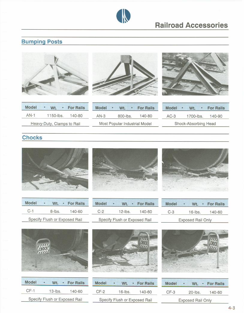
Bumping Posts
AN-1 1150-lbs. 140-80
Heavy-Duty, Clamps to Rail
AN-3 800-lbs. 140-80 AC-3 1700-lbs. 140-90
Most Popular Industrial Model Shock-Absorbing Head
Chocks
C-1 8-lbs. 140-60
Specify Flush or Exposed Rail
CF-1 13-lbs. 140-60
Specify Flush or Exposed Rail
C-2 12-lbs. 140-60
Specify Flush or Exposed Rail
CF-2 16-lbs. 140-60
Specify Flush or Exposed Rail
C-3 16-lbs. 140-60
Exposed Rail Only
CF-3 20-lbs. 140-60
Exposed Rail Only
4-3

_1-Railroad Accessories
Derails
Double
Single
100-lbs.
146-lbs.
40-lbs.
35-lbs.
140-60
140-40
Model N-19 . Hinged
Model N-22 . Portable
Double
Double
71-lbs.
43-lbs.
140-60
60-20
Single 73-lbs. 140-60
Double
Single
220-lbs.
280-lbs.
81-1bs.
92-lbs.
140-85
140-40
Model H-29 . Sliding
Model H-22 . Portable
Double
Single
65-lbs.
52-lbs.
136-75
136-75
4-4
41~Railroad Accessories
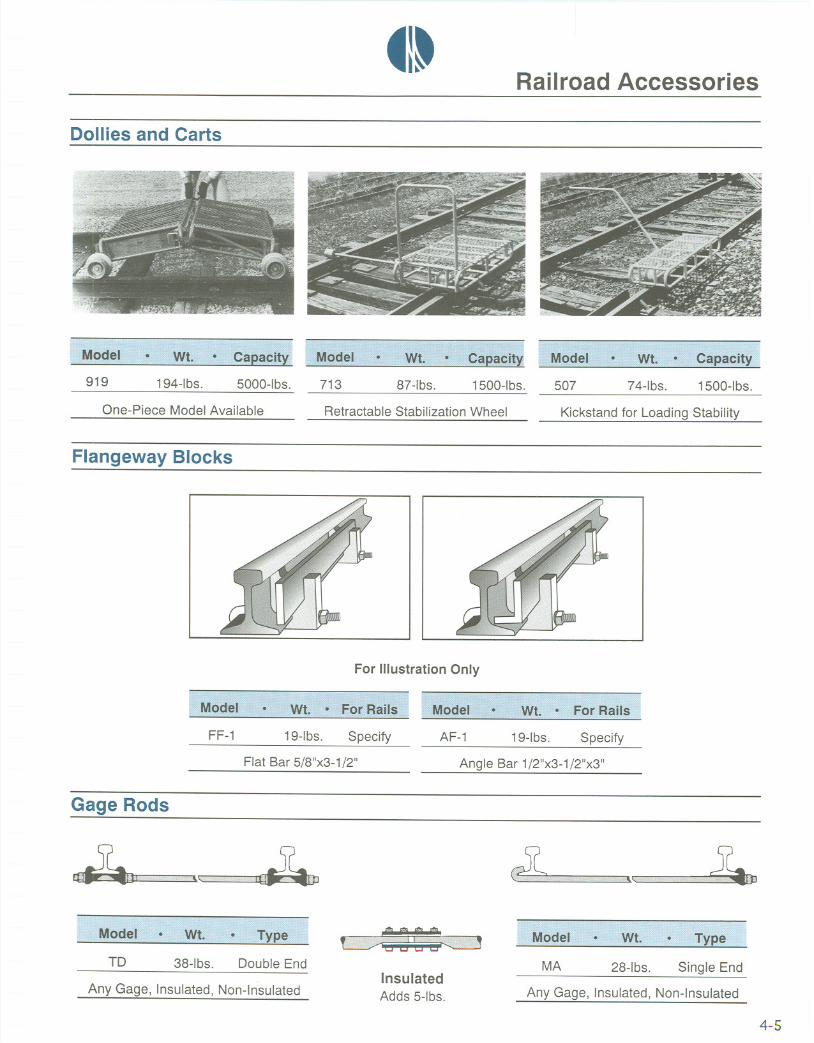
Dollies and Carts
919 194-lbs. 5000-lbs.
One-Piece Model Available
713 87-lbs. 1500-lbs. 507 74-lbs. 1500-lbs.
Retractable Stabilization Wheel Kickstand for Loading Stability
Flangeway Blocks
For Illustration Only
FF-1 19-1bs. Specify AF-1
Flat Bar 5/8"x3-1 /2"
19-1bs. Specify
Angle Bar 1/2"x3-1/2"x3"
Gage Rods
." "IT~,,"m££0£ "0££££" 0£hA
TD 38-lbs. Double End
Any Gage, Insulated, Non-Insulated
1!!ilITITiilIT~iW~ilE~TIilmWiiE!!
InsulatedAdds 5-lbs.
MA 28-lbs. Single End
Any Gage, Insulated, Non-Insulated
4-5

_1-Railroad Accessories
Rail Benders
Rerailers
Model HM-53 Model HM-54 Model HM-55
C-4 132-lbs. 8-680-40 326-lbs. 140-110
C-3 100-lbs. 60-30
(Capacity) C-4 (20T) C-3 (15T)
8-5 242-lbs. 100-85
(Capacity) 8-6 (200T) 8-5 (100T)
4-6
0-6 344-lbs. 140-85
0-5 360-lbs. 100-70
(Capacity) 0-6 (200T) 0-5 (100T)
H-140 181-lbs. 140-60 H-2 138-lbs. 70-60 2 100-lbs. 100-75
M-140 184-lbs. 140-60 H-3 95-lbs. 60-40 3 72-lbs. 75-50
H-Hydraulic* M-Journal Jack H-4 85-lbs. 40-25 4 58-lbs. 50-25*llIustrated
41~Railroad Accessories
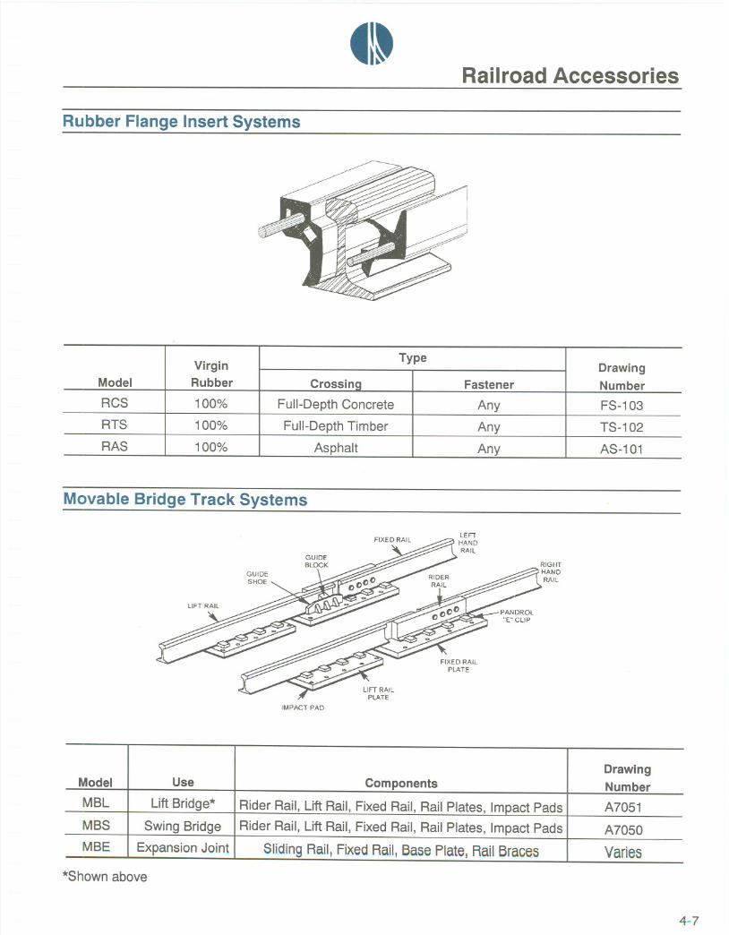
Rubber Flange Insert Systems
Movable Bridge Track Systems
GUIDEBLOCK
IMPACT PAD
*Shown above
4-7
VirginType
DrawingModel Rubber Crossina Fastener NumberRCS 100% Full-Depth Concrete Any FS-103
RTS 100% Full-Depth Timber Any TS-1 02
RAS 100% Asphalt Any AS-101
DrawingModel Use Components NumberMBL Lift Bridge* Rider Rail, Lift Rail, Fixed Rail, Rail Plates, Impact Pads A7051MBS Swing Bridge Rider Rail, Lift Rail, Fixed Rail, Rail Plates, Impact Pads A7050MBE Expansion Joint Sliding Rail, Fixed Rail, Base Plate, RailBraces Varies

_1-Railroad Accessories
I~ 4.75 ~
1
'f6.125I~
~ 4.351
1
'1'
I~ 5.40 ~
Steel Ties
All dimensions are in inches.
Type OSC Type SC
order:
4-8
Number Rail WeightThickness
100 90 85 80 75 70 60 40 30
Nine X X X X X X X .265Six X X X X X .195 - .166Five X X X .195 - .166Four X X .195 - .166

_I~Railroad Accessories
Stops, Skates and Skids
R-30 242-lbs. 140-60
Clamp-Type, No Holes Needed
R-34 388-lbs. Specify
Hinged, Optional Power Operator
NS-1 100-lbs. 140-85
Railroad Service Skate
R-32 220-lbs. 140-60
Wedge-Type, Se11-Tightening
R-36 270-lbs. 140-60
Cushion-Type, Two-Tie Contact
AS-1 60-lbs. 140-85
Industrial Service Skid
R-33 172-lbs. 119-60
Hinged-Type, Open Position
R-37 350-lbs. 140-60
Cushion-Type, No Holes Needed
XS-1 32-lbs. 80-40
Mine Service Skid
4-9

tl~Railroad Accessories
Track Tools*
*Alloyor steel. Other tools on request.
4-10
SizeEye Eye Handle Blade Small Large Spike A.R.E.A.
Articleand Description Weight Length No. Size Length or Bit Face Face Size Plan No.Q-13... 6lbs. 12" 11 1-3/4" 34" 4"x9" 12-62
x2"ADZE
FullHead
Q-43
9/16"
BAR271bs. 60" or 11-62
5/8"A.REA. Claw
Q-42
-- 181bs. 60" 5- 261bs. 66" 5
BARLining,DiamondPoint
Q-9------- 131bs. 40" 10-62----
FORKRail
Q-101"
MAUL
8lbs. 12" 2 x1-3/8" 36" 3/4" 1-1/2"10 Ibs. 12-3/4" 2 1" 36" 1" 1-3/4"
x1-3/8"Standard Pattern Spike
Q-11
MAUL
1"3
101bs. 15" 2x1-3/8"
36" 1-1/4" 1-5/8" Des.2
BellPattern Spike
Q-15
UNCH
5-1/2 Ibs. 13" 3 3/4"x 24" 191-3/8"
Track Round

41~Railroad Accessories
Track Tools*
*Alloy or steel. Other tools on request.
4-11
Bolt A.R.E.A.Size Plan No.
Q-14
12-1/2 Ibs.1 12" 1 3/4" I I 9PULLER
Spike 4 Ball
Q-16
---r--TONG
Distance
I
3-3/4"across18 Ibs.
handlesI I 6
44"Rail
Q-17
¥TONG
Distance
121bs.across
1 15-1/2" I I 8handles41-3/4"
Timber
Q-20
I 8lbs. I
30" 1-5/16" 3/4" I 4
101bs. 36" 1-1/2" 7/8" I 4
121bs. 42" 1-11/16" 1" I 4
141bs. 48" 1-7/8" 1-1/8" I 4
161bs. 48" 2-1/16" 1-1/4" I 4
TRACKWRENCHES 118 Ib 54" 2-1/4" 1-3/8" I 4SingleEnd s.Q-21
101bs. 36" 1-5/16" - 1-1/2" 3/4"-7/8" I 4
121bs. 42" 1-1/2" - 1-11/16" 7/8"-1" I 4
141bs. 48" 1-11/16"-1-7/8" 1"-1/8" I 4
48" 1-7/8"-2-1/16" 1-1/8"-1-1/4" I 4TRACKWRENCHES
DoubleEnd 48" 2-1/16"-2-1/4" 1-1/4"-1-3/8" I 4
Q-2<!1
I".....,.5lbs. I 62"

~I-Railroad Accessories
Barrier Gate . Wood Ties. Car Mover
BG-1 400-lbs. Max. 24 ft.
Twelve Controls Available
CM-1 20-lbs. 70" 7"x9"x8'-6" Specify
6"x8"x8'-6" Specify
245-lbs.
187-Ibs.Hand Guard Available
Rail Anchors . Rail Tongs. Rail Puller
ARD
ARS
Drive-on Specify
SpecifySpring
4-12
RPN 46-lbs. 140-100
Easily Attached or Removed
CT-1 52-lbs. All
Designed to Lift, Not Drag


tl~u[}={]~@(Q)[UJ~~~[Q)@@~
Crane Rail Accessories. Every crane rail system must have a method to anchor the railto the structure. Atlantic Track & Turnout Co. can supply any hold-down devicespecified by the crane manufacturer or the design engineer. Seventy years of experiencebacked up by historical data indicates that 90 percent of all runways are held down byeither hook bolts, rail clips or rail clamps.
We manufacture twenty-two different types of stops. All stops are furnished with ASTMA-32S, medium-carbon, heat-treated machine bolts complete with heavy hex nuts andlockwashers.
Crane rail pads and rubber nose clips are available for soft-mounted crane rail systems.Bolted or weldable two-piece clips provide easy replacement or re-alignment of existingrunways. The entire system adds to the life of the rail, reduces wear on the crane andpreserves the integrity of the structure.
In-house fabrication and large inventories assure fast shipment of a total crane runwaysystem.
Note: Brand-to-brand installation is highly recommended on all crane runwayconstruction. The raised brand rail web identification should be on the same side for allconnected rails.
For complete details, see THE CRANE RAIL BOOK.
5-1

~I~Crane Rail Accessories
Hook Bolts
Atlantic Track can supply hook bolts for use with all railsections. Hook bolts are the most frequently specifiedhold-down devices for rails 85-lb per yard or less. Our hookbolts are furnished complete with hex nuts and lockwashers.
Rail Clips
Large inventories of rail clips are available for most railsections. Tolerances are tl/32; however, please check currentdimensions before prefabrication of runway beams orchannels.
Rail Clamps
Our single, double, tight or loose fit clamp andreversible filler sets are available for all rail sections. Clampsallow for easy adjustment in alignment during installation. Inaddition, studs can be welded to the filler plate wherethru-floor fastening is impossible.
Heavy Duty Clamps
We can supply either clip and holder or clip and U-barsets which are welded to the runway structure for severeservice applications. Both can be furnished as single ordouble hole and are adjustable for tight or loose fit.
Gantry System Clips
These special clips consist of two interacting componentswhich allow easy lateral rail adjustment and, once correctlyinstalled, are self-locking. A controlled vertical force isapplied to the rail flange through a synthetic rubber "nose"which is vulcanize-bonded to the appropriate clip component.
For complete details, see THE CRANE RAIL BOOK.
5-2
~

_I~Crane Rail Accessories
Gantry System Pads
Combining the proper pad and rubber nose clipproduces a soft-mounted crane rail system that extends thelife of the rail, wheels, axles and collector shoes. AtlanticTrack offers pads for use in light, moderate and severe service.
Crane Stops
Atlantic Track & Turnout Co. manufactures seventeen
different types of crane stops. These stops can be suppliedwith or without a bumper plate and/ or a steel filler.Depending on the runway, stops will be supplied as two orthree-hole design. To order, please specify rail weight andsection plus standard or heavy duty.
Wheel Stops
We manufacture wheel stops to fit 175-lb crane rail to20-lb ASCE tee rail. Two or three-hole stops are furnishedaccording to the rail weight of the runway. To order, pleasespecify rail weight and section plus wheel diameter.
Portable Wheel Stops
These stops are used in pairs for temporary protectionwhen cranes are being overhauled. Impact of crane wheeldrives wedge deeper into slot through cinch plates that createdrag to gradually bring the crane to a stop. To order, pleasespecify rail weight and section plus wheel diameter.
Warning: Do not use as a permanent crane or wheel stop.
For complete details, see THE CRANE RAIL BOOK.
5-3


_I~u[H]~ ~(Q)lUJ~~~[Q)@@~
General Information. The final section of the THE SOURCEbook contains abbreviations,conversion tables, general rail specifications and the current ASTM specifications forcarbon steel rails.
Physical properties of rail are governed by design and do not vary from manufacturer tomanufacturer. Chemical properties on crane rail, heavy tee rail and standard tee rail arealso constant and match the chemical specifications in the tables that follow.
Since chemical content of light tee rail does vary from manufacturer to manufacturer, ourtable for these sections shows a combination of published specifications. In addition, wecan supply 60-lb ASCE through 25-lb ASCE rail conforming to ASTM Specification A-I.Light tee rail can also be supplied with low carbon content for welding.
The specifications in this section have been extracted from the following sources:*
(1) Professional engineering literature
(2) Manufacturers' catalogs
(3) Atlantic Track Estimating Department
(4) Combinations of the above
The information presented in this catalog, including engineering data, tables, figures,designs, details and supporting data should not be used without independentexamination and verification of its suitability by a licensed structural engineer, licensedprofessional engineer or a competent licensed architect. Atlantic Track & Turnout Co.disclaims any and expressed or implied warranties, without limitations, andparticularly that of fitness for any general or particular purpose in regard to informationcontained or referred to herein. Anyone making use of the information and contents ofthis catalog assumes all liability arising from such use.
* In some cases, charts have been rearranged to fit the catalog format.In addition, information not related to our product has been deleted.
6-1

_I~
Industry AbbreviationsInitials Definition
ATTBHNBRCCCHCR
CWRCWTDINDMDYFTFTGNGTHT
HTTIN
JISKG/MLBS
LBSIYDLDLFLHMHNTOH
OTMPRRPSPW
RBMRGRHRR
SMSGT
TFTO
TS&MVT
Atlantic Track & Turnout Co.Brinell Hardness NumberBolted Rigid (Frog)Control CooledEnd HardenedCrane RailContinuous Welded RailOne Hundred PoundsDeutsche Industries NormChicago & NorthwesternDudleyFlat Top (Frog)Heat Treated (Branding)Great NorthernGross Ton (2,240 Ibs.)Heat TreatedHook Twin Tie PlateInchesJapanese Industrial StandardKilograms/MeterPoundsPoundslYardLight DensityLineal or Linear; Foot or FeetLeft HandMedium HardnessNet Ton (2,000 Ibs.)Open HearthOther Track MaterialPennsylvania RailroadPennsylvania SystemPartly WornRail Bound Manganese (Frog)ReadingRight HandRailroadSolid Manganese Self-Guarded (Frog)Metric Tonne (2,204 Ibs.)Track; Foot or FeetTurnoutTongue Switch & MateVacuum Degassed
6-2

41~
Association AbbreviationsInitials Organization
AISCAISEASLRAAISIAMCASCEASTMARA
Type AType B
AREACMAANRCMHIREMSA
American Institute of Steel Construction, Inc.Association of Iron and Steel EngineersAmerican Short Line RailroadAssociationAmerican Iron and Steel InstituteAmerican Mining CongressAmerican Society of Civil EngineersAmerican Society for Testing and MaterialsAmerican Railway Association
High Speed RailSlow Speed Rail
American Railway EngineeringAssociationCrane ManufacturersAssociation of America, Inc.National Railroad Construction and Maintenance Association, Inc.Material Handling InstituteRailroad Equipment ManufacturersAssociation
u.s. Units and Metric Equivalents
6-3
Weights and Measures Conversion Tables
Lenath Length
Feet to Meters Meters to FeetMILE 1.6093 km
(m)YARD (yd) .9144 m (ft) (m) (ft)
FOOT (ft) 0.3048 m 3.281 1 .3048 1
INCH (in) 25.4 mm 9.843 3 .9144 3KILOMETER (km) 0.6214 mile 98.430 30 9.1440 30METER (m) 1.0936 yd 108.273 33 10.0580 33CENTIMETER (cm) 0.3937 in 127.959 39 11.8870 39MILLIMETER (mm) 0.0394 in
328.100 100 30.4800 100
Weiaht Weight
GROSS TON (gt) 2240lb 1.016 t Ib kg gt t ntNET TON (nt) 2000lb .907 t 2240 1016.06 1.00 1.02 1.12CWT 100lb 45.359 kg 2204 1000.00 .98 1.00 1.10POUND (Ib) 160z 0.454 kg 2000 907.44 .89 .91 1.00METRIC TON (t) 22041b .984 gtMETRICTON (t) 22041b 1.102 nt Ibs/yd X .4961 = KILOGRAMS/METERKILOGRAM (kg) 1000 gr 2.204 Ib kg/m + .4961 = POUNDS/YARD

~I~
Physical Properties Crane Rail AISC
Reprinted courtesy of the American Institute of Steel Construction, Inc.
Chemical Properties Crane Rail ASTM A-759
Reprinted courtesy of the American Institute of Steel Construction, Inc.
Physical Properties Heavy Tee Rail AREA
*Not from AREA - ATT Estimating Department
Reprinted courtesy of the American Railway Engineering Association.
6-4
Properties of SectionSectional Moment Neutral Section Modulus
Rail Weight Area of Inertia Axis. Y Head Baseand Section Inches2 Inches 4 Inches Inches3 Inches3
175-lb CRANE 17.10 70.20 3.02 23.50 23.30
171-lb CRANE 16.80 73.40 3.01 24.50 24.40
135-lb CRANE 13.30 50.60 2.81 17.20 18.00
105-lb CRANE 10.30 34.40 2.41 12.40 14.30
104-lb CRANE 10.30 29.80 2.21 10.70 13.50
Rail Weight Carbon Manganese Phosphorus Sulfur Siliconand Section
175-lb CRANE .67 to .82 .70 to 1.00 .04 max .05 max .10 to .30
171-lb CRANE .67 to .82 .70 to 1.00 .04 max .05 max .10 to .30
135-lb CRANE .67 to .82 .70 to 1.00 .04 max .05 max .10 to .30
105-lb CRANE .67 to .82 .70 to 1.00 .04 max .05 max .10 to .30
104-lb CRANE .67 to .82 .70 to 1.00 .04 max .05 max .10 to .30
Properties of SectionSectional Moment Neutral Section Modulus
Rail Weight Area of Inertia Axis. Y Head Baseand Section Inches2 Inches 4 Inches Inches3 Inches3
140-lb AREA 13.80 96.80 3.37* 24.60 28.70
136-lb AREA 13.35 94.90 3.35* 23.90 28.30
133-lb AREA 13.08 86.00 3.20* 22.00 27.00
132-lb AREA 12.95 88.20 3.20* 22.50 27.60
119-lb AREA 11.65 71.40 3.12* 19.40 22.90
115-lb AREA 11.25 65.60 2.98* 18.00 22.00

~I~
Chemical Properties Heavy Tee Rail ASTM A-1
Reprinted courtesy of the American Society for Testing and Materials.
Phy~ical Properties Standard Tee Rail AISC
*Not from AISC. Accumulated from various manufacturers.Reprinted courtesy of the American Institute of Steel Construction, Inc.
Chemical Properties Standard Tee Rail ASTM A-1
*Can be supplied to manufacturers specifications.
Reprinted courtesy of the American Society for Testing and Materials. 6-5
Rail Weight Carbon Manganese Phosphorus Sulfur Siliconand Section
140-lb AREA .72 to .82 .80 to 1.10 .035 max .04 max .10 to .50
136-lb AREA .72 to .82 .80 to 1.10 .035 max .04 max .10 to .50
133-lb AREA .72 to .82 .80 to 1.10 .035 max .04 max .10 to .50
132-lb AREA .72 to .82 .80 to 1.10 .035 max .04 max .10 to .50
119-lb AREA .72 to .82 .80 to 1.10 .035 max .04 max .10 to .50
115-lb AREA .72 to .82 .80 to 1.10 .035 max .04 max .10 to .50
Properties of SectionSectional Moment Neutral Section Modulus
Rail Weight Area of Inertia Axis. Y Head Baseand Section Inches2 Inches 4 Inches Inches
3Inches3
1OO-IbARA-A 9.84 48.90 2.75 15.00 17.80*
1OO-IbARA-B 9.85 41.30 2.63 13.70 15.72*
1OO-IbAREA 9.95 49.00 2.75 15.10 17.80*
90-lb ARA-A 8.82 38.70 2.54 12.60 15.20*
85-lb ASCE 8.33 30.10 2.47 11.10 12.17*
80-lb ASCE 7.86 26.40 2.38 10.10 11.08*
70-lb ASCE 6.81 19.70 2.22 8.20 8.87*
Rail Weight Carbon Manganese Phosphorus Sulfur Siliconand Section
1OO-IbARA-A .67 to .80 .70 to 1.00 .035 max .04 max .10 to .501OO-IbARA-B .67 to .80 .70 to 1.00 .035 max .04 max .10 to .50
1OO-IbAREA .67 to .80 .70 to 1.00 .035 max .04 max .10 to .50
90-lb ARA-A .67 to .80 .70 to 1.00 .035 max .04 max .10 to .50
85-lb ASCE .67 to .80 .70 to 1.00 .035 max .04 max .10 to .50
80-lb ASCE .55 to .68 .60 to .90 .040 max .05 max .10 to .5070-lb ASCE .55 to .68 .60 to .90 .040 max .05 max .10 to .50
60-lb ASCE* .55 to .68 .60 to .90 .040 max .05 max .10 to .50

_I~
Physical Properties Light Tee Rail Manufacturers
Chemical Properties Light Tee Rail Industry Range
*Can be supplied to ASTM A-1.
Brinell Hardness Number Manufacturers Range
6-6 *Manufacturers target 270 to 278
Properties of SectionSectional Moment Neutral Section Modulus
Rail Weight Area of Inertia Axis. Y Head Baseand Section Inches2 Inches 4 Inches Inches3 Inches3
60-lb ASCE 5.93 14.60 2.05 6.60 7.10
40-lb ASCE 3.94 6.54 1.68 3.59 3.89
30-lb ASCE 3.00 4.10 1.52 2.55 2.70
25-lb ASCE 2.40 2.50 1.33 1.76 1.88
20-lb ASCE 2.00 1.93 1.26 1.41 1.53
16-lb ASCE 1.57 1.23 1.14 .99 1.08
12-lb ASCE 1.18 .74 .97 .72 .76
Rail Weight Carbon Manganese Phosphorus Sulfur Siliconand Section
60-lb ASCE* .50 to .70 .60 to 1.00 .045 max. .05 max. .07 to .50
40-lb ASCE* .40 to .65 .60 to 1.00 .045 max. .05 max. .40 max.
30-lb ASCE* .40 to .65 .60 to 1.00 .045 max. .05 max. .40 max.
25-lb ASCE* .40 to .60 .50 to .90 .045 max. .05 max. .40 max.
20-lb ASCE .40 to .60 .50 to .90 .045 max. .05 max. .40 max.
16-lb ASCE .40 to .60 .50 to .90 .045 max. .05 max. .40 max.
12-lb ASCE .40 to .60 .50 to .90 .045 max. .05 max. .40 max.
Control-Cooled Heat-Treated
Type Rail Minimum Maximum Minimum Maximum
Crane Rail None Specified* None Specified 321 388
Tee Rail
140-lb to 115-lb 300 None Specified 341 388
1OO-Ibto 85-lb 248 None Specified 321 388
80-lb 201 None Specified 277 341
60-lb 201 260 277 341
40-lb 180 250 N/A N/A
30-lb 176 230 N/A N/A
25-lb to 12-lb 176 187 N/A N/A
~I~
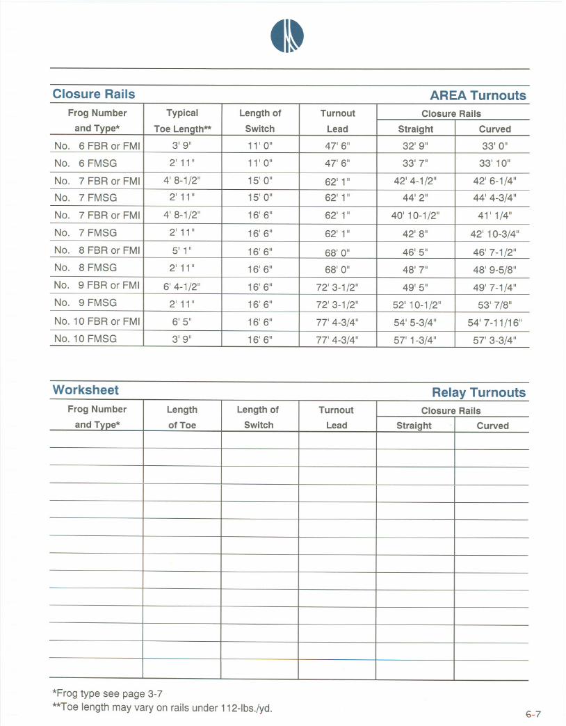
Closure Rails AREA Turnouts
Worksheet Relay Turnouts
*Frog type see page 3-7**Toe length may vary on rails under 112-lbs./yd. 6-7
Frog Number Typical Length of Turnout Closure Rails
and Type* Toe Length** Switch Lead Straight Curved
NO.6 FBR or FMI 3'9" 11' 0" 47' 6" 32' 9" 33'0"
NO.6 FMSG 2' 11" 11' 0" 47' 6" 33' 7" 33' 10"
NO.7 FBR or FMI 4' 8-1/2" 15' 0" 62' 1" 42' 4-1/2" 42' 6-1/4"
NO.7 FMSG 2' 11" 15' 0" 62' 1" 44'2" 44' 4-3/4"
NO.7 FBR or FMI 4' 8-1/2" 16' 6" 62' 1" 40' 10-1/2" 41' 1/4"
NO.7 FMSG 2' 11" 16' 6" 62' 1" 42'8" 42' 10-3/4"
No.8 FBR or FMI 5' 1" 16' 6" 68'0" 46' 5" 46' 7-1/2"NO.8 FMSG 2' 11" 16' 6" 68'0" 48'7" 48' 9-5/8"NO.9 FBR or FMI 6' 4-1/2" 16' 6" 72' 3-1/2" 49'5" 49' 7-1/4"NO.9 FMSG 2' 11" 16' 6" 72' 3-1/2" 52' 10-1/2" 53' 7/8"
NO.10 FBR or FMI 6' 5" 16' 6" 77' 4-3/4" 54' 5-3/4" 54' 7-11/16"
NO.10 FMSG 3' 9" 16' 6" 77' 4-3/4" 57' 1-3/4" 57' 3-3/4"
Frog Number Length Length of Turnout Closure Rails
and Tvpe* of Toe Switch Lead Straight Curved
41-
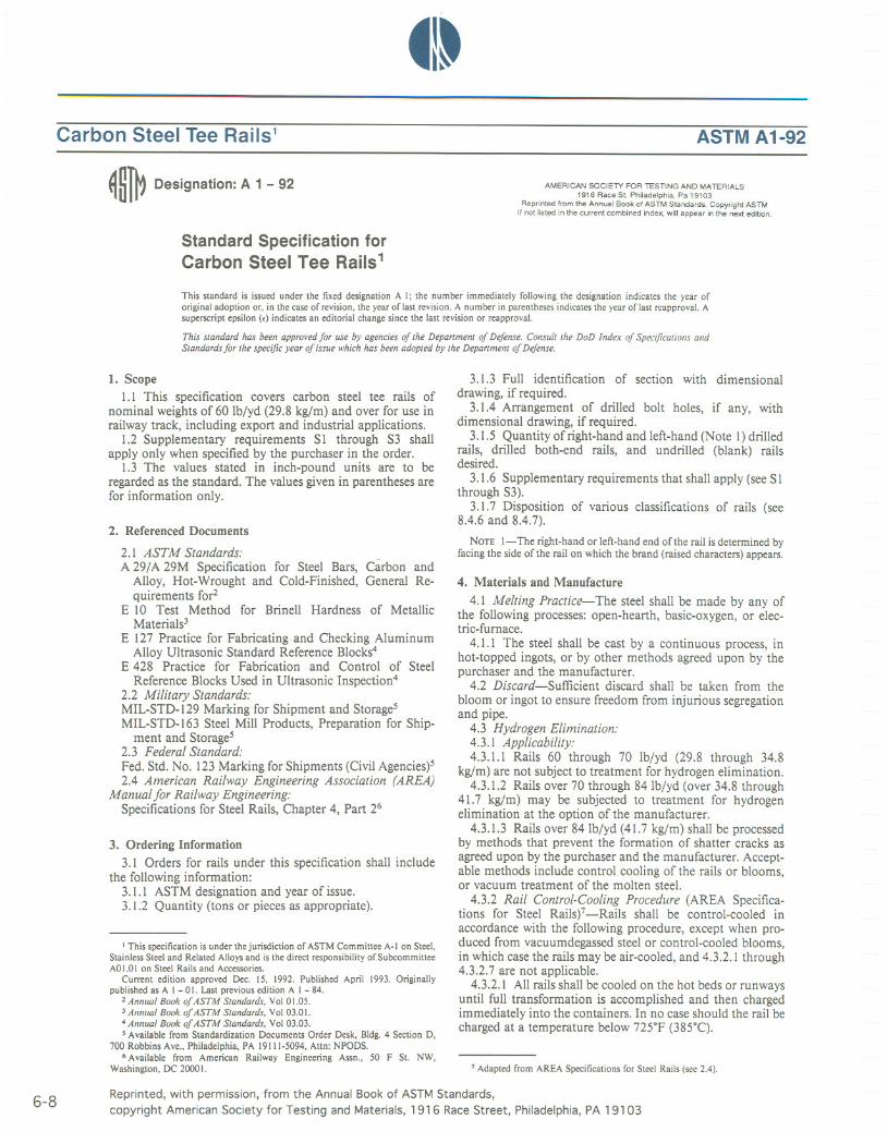
Carbon Steel Tee Rails1 ASTM A1-92
~ ~1~ Designation: A 1 - 92
Standard Specification forCarbon Steel Tee Rails1
AMERICAN SOCIETY FOR TESTING AND MATERIALS1916 Race St. Philadelphia, Pa 19103
Reprinted from the Annual Book of ASTM Standards. Copyright ASTMIf not listed in the current combined index, will appear in the next ed"ion.
This standard is issued under the fixed designation A I; the number immediately following the designation indicates the year oforiginal adoption or. in the caseof revision. the year of last revision, A number in parenthesesindicates the year of last reapprovaL Asuperscriptepsilon(E) indicatesaneditorialchangesincethe lastrevisionor reapprovaL
This standard has been approved Jor use by agencies oj the Department oj DeJense. Consult the DoD Index oj Specifications andStandards Jor the specific year oj issue which has been adopted by the Department oj DeJense,
1. Scope1.1 This specification covers carbon steel tee rails of
nominal weights of 60 Ib/yd (29.8 kg/m) and over for use inrailway track, including export and industrial applications.
1.2 Supplementary requirements SI through S3 shallapply only when specified by the purchaser in the order.
1.3 The values stated in inch-pound units are to beregarded as the standard. The values given in parentheses arefor information only.
2. Referenced Documents
2.1 ASTM Standards:A 29/A 29M Specification for Steel Bars, Carbon and
Alloy, Hot-Wrought and Cold-Finished, General Re-quirements for2
E 10 Test Method for Brinell Hardness of MetallicMaterials3
E 127 Practice for Fabricating and Checking AluminumAlloy Ultrasonic Standard Reference Blocks4
E 428 Practice for Fabrication and Control of SteelReference Blocks Used in Ultrasonic Inspection4
2.2 Military Standards:MIL-STD-129 Marking for Shipment and Storage5MIL-STD-163 Steel Mill Products, Preparation for Ship-
ment and Storage52.3 Federal Standard:Fed. Std. No. 123 Marking for Shipments (Civil Agencies)52.4 American Railway Engineering Association (AREA)
Manual for Railway Engineering:Specifications for Steel Rails, Chapter 4, Part 26
3. Ordering Information3.1 Orders for rails under this specification shall include
the following information:3.1.1 ASTM designation and year of issue.3.1.2 Quantity (tons or pieces as appropriate).
I This specification is under the jurisdiction of ASTM Committee A-Ion Steel.StainlessSteel and Related Alloysand is the direct responsibilityof SubcommitteeAO1.0I on Steel Rails and Accessories.
Current edition approved Dec. 15, 1992. Published April 1993. Originallypublished as A I -0I. Last previousedition A I - 84.
2 Annual Book oj ASTM Standards, Vol 01.05.3 Annual Book ojASTM Standards. Vol 03.01.4 Annual Book oj ASTM Standards, Vol 03.03., Availablefrom Standardization Documents Order Desk, Bldg. 4 Section D.
700 Robbins Ave., Philadelphia, PA 19111-5094, Attn: NPODS.6 Available from American Railway Engineering Assn., 50 F SI. NW,
Washington, DC 20001.
3.1.3 Full identification of section with dimensionaldrawing, if required.
3.1.4 Arrangement of drilled bolt holes, if any, withdimensional drawing, if required.
3.1.5 Quantity of right-hand and left-hand (Note 1) drilledrails, drilled both-end rails, and undrilled (blank) railsdesired.
3,1.6 Supplementary requirements that shall apply (see SIthrough S3).
3.1.7 Disposition of various classifications of rails (see8.4.6 and 8.4.7).
NOTE I-The right-hand or left-hand end of the rail is determined byfacing the side of the rail on which the brand (raised characters) appears.
4. Materials and Manufacture
4.1 Melting Practice-The steel shall be made by any ofthe following processes: open-hearth, basic-oxygen, or elec-tric-furnace.
4.1.1 The steel shall be cast by a continuous process, inhot-topped ingots, or by other methods agreed upon by thepurchaser and the manufacturer.
4.2 Discard-Sufficient discard shall be taken from thebloom or ingot to ensure freedom from injurious segregationand pipe.
4.3 Hydrogen Elimination:4.3.1 Applicability:4.3.1.1 Rails 60 through 70 lb/yd (29.8 through 34.8
kg/m) are not subject to treatment for hydrogen elimination.4.3.1.2 Rails over 70 through 84 lb/yd (over 34.8 through
41.7 kg/m) may be subjected to treatment for hydrogenelimination at the option of the manufacturer.
4.3.1.3 Rails over 84 lb/yd (41.7 kg/m) shall be processedby methods that prevent the formation of shatter cracks asagreed upon by the purchaser and the manufacturer. Accept-able methods include control cooling of the rails or blooms,or vacuum treatment of the molten steel.
4.3.2 Rail Control-Cooling Procedure (AREA Specifica-tions for Steel Railsf -Rails shall be control-cooled inaccordance with the following procedure, except when pro-duced from vacuumdegassed steel or control-cooled blooms,in which case the rails may be air-cooled, and 4.3.2.1through4.3.2.7 are not applicable.
4.3.2.1 All rails shall be cooled on the hot beds or runwaysuntil full transformation is accomplished and then chargedimmediately into the containers. In no case should the rail becharged at a temperature below 72soF (385"C).
7 Adapted from AREA Specifications for Steel Rails (see2.4).
6-8 Reprinted, with permission, from the Annual Book of ASTM Standards,copyright American Society for Testing and Materials, 1916 Race Street, Philadelphia, PA 19103

~I~
4.3.2.2 The temperature of the rails before charging shallbe determined with a reliablecalibrated pyrometer at the topof the rail head at least 12in. (305 mm) from the end.
4.3.2.3 The cover shall be placed on the container imme-diately after completion of the charge and shall remain inplace for at least 10 h. After removal or raising of the lid ofthe container, no rail shall be removed until the top layer ofrails has fallen to 300°F (149°C)or lower.
4.3.2.4 The temperature between an outside rail and theadjacent rail in the bottom tier of the container at a point notless than 12 in. (305 mm) nor more than 36 in. (915 mm)from the rail end shall be recorded. This temperature shallbethe control for judging rate of cooling.
4.3.2.5 The container shall be so protected and insulatedthat the control temperature shall not drop below 300°F(149°C)in 7 h for rails 100 Ib/yd (49.7 kg/m) in weight orheavier, from the time that the bottom tier is placed in thecontainer, and in 5 h for rails of less than 100 Ib/yd inweight. If this cooling requirement is not met, the rails shallbe considered control-cooled,provided that the temperatureat a location not lessthan 12in. (305 mm) from the end of arail at approximately the center of the middle tier does notdrop below 300°Fin less than 15 h.
5. ChemicalComposition5.1 The chemical composition of the standard rail steel,
determined as prescribed in 5.2.1, shall be within the limitsshown in Table I.
5.1.1 When ladle tests are not available, finished materialrepresenting the heat may be product tested. The productanalysis allowance beyond the limits of the specified ladleanalysis shall be within the limits for product analysesspecifiedin Table 2.
5.2 Heat or Cast Analysis:5.2.1 Separate analysis shall be made from test samples
representing one of the first three and one of the last threeingots or continuously cast blooms preferably taken duringthe pouring of the heat. Determinations may be madechemically or spectrographically.Any portion of the heatmeeting the chemical analysis requirements of Table I maybe applied. The first heat analysis shall be recorded as theofficial heat analysis, but the purchaser shall have accesstoall ladle analyses. Additionally, any material meeting theproduct analysis limits shown in Table 2 may be appliedafter testing such material in accordance with SpecificationA 29/A 29M.
TABLE1 ChemicalRequirements-Heat Analysis
NominalWeight, Ibfyd (kgfm)
60 to 84 85 to 114(29.8 to (42.2 to41.7), 56.6),incl incl
Element 115(57.0)
and over
Carbon 0.55 to 0.68 0.67 to 0.80 0.72 to 0.82Manganese 0.60 to 0.90 0.70 to 1.00 0.80 to 1.10APhosphorus,max 0.040 0.035 0.035Sulfur,max 0.050 0.040 0.040Silicon 0.10 to 0.50 0.10 to 0.50 0.10 to 0.50
AThe uppermanganeselimitmaybeextendedto 1.25%bythemanufacturerto meet the Brinellhardnessspecification.Whenmanganeseexceeds1.10%,theresidualalloy contents will be held to 0.25 % maximumnickel; 0.25% maximumchromium;0.10% maximummolybdenum;and 0.03 %maximumvanadium.
~t A 1
TABLE 2 Product Analysis Allowance Beyond Limits of SpecifiedChemical Analysis
A Continuously cast allowances shall be 0.05 % over maximum limit for silicon.
5.2.2 Upon request by the purchaser, samples shall befurnished to verify the analysis as determined in 5.2.1.
6. Interior Condition
6.1 For ingot steel, nick and break or macroetch testingshall be performed as agreedupon by the purchaser and themanufacturer. For continuously cast steel, macroetch testingshall be performed.
6.2 Nick and Break Testing-A full-size test specimenrepresentingthe top end of the top rail of each ingot of eachheat rolledshall be nicked and broken. If the fracture on anytest specimenexhibits seams, laminations, cavities,evidenceof injurious segregation, or interposed foreign matter, theheat number and ingot number shallbe recorded and the topend and bolt holes of the finished rail, so recorded, shall becloselyexamined for those conditions. If the finished rail isclear of the aforementioned conditions when presented forinspection, it shall be accepted as a No. I. If the finished railshows any of the above conditions, it shall be cut or brokenback to sound metal and accepted as a short rail, subject tothe requirements of 8.3.2, 8.3.3, and Section 10.
6.2.1 The requirements of 6.2 may be waived if thepurchaser requests the application of S2.
6.3 MacroetchTesting-Rail soundnessshall be evaluatedby macroetching in a hot acid solution.
6.3.1 Sample Location and Frequency:6.3.1.1 Ingot Steel-A test piece representing the top end
of the top rail from one of the first three, middle three, andlast three ingots of each heat shall be macroetched.
6.3.1.2 Continuous Cast Steel-A test piece shall bemacroetched representing a rail from each strand from thebeginning of each sequence and whenever a new ladle isbegun, which is the point representativeof the lowestlevel inthe tundish (that is, the point of lowest ferrostatic pressure).One additional sample from the end of each strand of the lastheat in the sequence shall also be tested. A new tundish isconsidered to be the beginning of a new sequence.
6.3.2 If any test specimen does not conform to theacceptable macroetch pictorial standards agreed to by thepurchaser and the manufacturer, further samples shall betaken from the same strand or ingot. For continuously caststeel two retests shall be taken one from each side of theoriginal sample at positions decided by the manufacturer,and the material between the two retest positions shall berejected.For ingot steeltestingshall progressdown the ingot.If any retest fails, testing shall continue until acceptableinternal quality is exhibited. All rails represented by failedtests shall be rejected.
Reprinted, with permission, from the Annual Book of ASTMStandards,copyright AmericanSociety for Testing and Materials,1916 Race Street, Philadelphia, PA 19103
6-9
PercentUnder PercentOverMinimumLimit MaximumLimit
Carbon 0.04 0.04Manganese 0.06 0.06Phosphorus ... 0.008Sulfur ... 0.008Silicon 0.02 0.02A

~I~
7. Hardness Properties7.1 Rails shall be produced to hardness levels in accor-
dance with Table 3.7.2 A Brinellhardnesstest shallbe performed at least 1 in.
(25.4 mm) from the end of a rail of each heat of steel. Oralternatively on a sample ofrail cut at least 6 in. (152 mm)from the end of the rail of each heat of steel.
7.2.1 The test shall be made on the side or top of the railhead after decarburized material has been removed, topermit an accurate determination of hardness.
7.2.2 The test shall otherwisebe conducted in accordancewith the current edition of Test Method E 10.
7.3 If any test rail or rail sample fails to meet therequirements of 7.1, it shall be checked by making twoadditional hardness measurements, one on each side of thepoint first measured and each approximately 1 in. from thatpoint. If both of these check measurements meet therequirements of 7.1, the heat shall be consideredto have metthe requirements of 7.1.
7.4 If the test rail or rail sample fails the hardness retestrequirements of 7.3, the manufacturer may test hardnessindividually for all of the rails of that heat. Those meetingthe requirements of 7.1 or 7.3 shall be acceptable,and thosenot meeting the requirements will be rejected.
8. Permissible Variations of Dimension,Weight, and OtherPhysical Attributes
8.1 Section:8.1.1 The section of the rail shall conform to the design
specifiedby the purchaser.8.1.2 A variation of 0.015 in. (0.38 mm) less or 0.040 in.
(1.02 mm) greater than the specifiedheightwill be permittedmeasured at least I in. (25.4 mm) from each end.
8.1.3 A variation of 0.040 in. (1.02 mm) less or 0.040 in.greater than the specified rail head width will be permittedmeasured at least 1 in. (25.4 mm) from each end.
8.1.4 A variation of 0.060 in. (1.5 mm) in the width ofeither flangewillbe permitted but the variation in total widthof the base shall not exceed0.060 in.
8.1.5 No variation will be allowedin dimensions affectingthe fit of the joint bars, except that the fishing templateapproved by the purchaser may stand out laterally not morethan 0.060 in. (1.5 mm) when measured within the 18-in.(460-mm) end locations.
8.1.6 Verificationof tolerancesshall be made using appro-priate gagesas agreed upon by purchaser and manufacturer.
8.2 Length:8.2.1 The standard length of rails shallbe 39 ft (11.9m) or
80 ft (24.4 m), or both, when measured at a temperature of60°F (15°C).
8.2.2 Up to 9 % for 39 ft rail or 15 % for 80 ft rail of theentire order will be accepted in lengths shorter than thestandard,varyingby I ft (0.3m) as follows:79, 78, 77, 75,
TABLE 3 Hardness Requirements of Standard Carbon Rails
NominalWeight,Ib/yd(kg/m)
60 to 84 85 to 114(29.8 to 41.7). (42.2 to 56.6),
inel inel
115 (57.0)and over
Srinell Hardness, min 201 248 285
4t A 1
70,65,60, 39, 38, 37, 36, 33, 30, 27, and 25 ft.8.2.3 A variation 0£7/16in. (11 mm) for 39 ft (11.9 m) rails
or 7/8in. (22 mm) for 80 ft rails will be permitted.8.2.4 Length variations other than those specifiedin 8.2.2
and 8.2.3 may be established by agreement between thepurchaser and the manufacturer.
8.3 Drilling:8.3.1 Circular holes for joint bolts shall be drilled to
conform to the drawings and dimensions furnished by thepurchaser.
8.3.2 A variation of -0 and +1/16in. (1.6 mm) in the sizeof the bolt holes will be permitted.
8.3.3 A variation of 1/32in. (0.8 mm) in the location of theholes will be permitted.
8.3.4 Fins and burrs at the edges of bolt holes shall beeliminated. The drilling process shall be controlled to pre-vent mechanical or metallurgicaldamage to the rail.
8.3.5 When right-hand and left-hand drilling is specified,at least the minimum quantity of each indicated by thepurchaser will be supplied. The excess on anyone-enddrilling will be applied against the order.
8.3.6 Disposition of rails classified "A" and short rails,with respect to application as right-hand drilled, left-handdrilled, and blank rails, if such categoriesare specifiedin theorder, shall be established by agreement between the pur-chaser and the manufacturer.
8.3.7 Dispositionof shortrailsthat accruefromleft-handdrilled, right-hand drilled, and undrilled (blank) rail produc-tion, and which are acceptablein accordancewith 8.2.2 shallbe establishedby agreement between the purchaser and themanufacturer.
8.4 Finish:8.4.1 Rails shall be straightened cold in a press or roller
machine to remove twists,waves,and kinks, until they meetthe surface and line requirements specifiedin 8.4.2 through8.4.5, as determined by visual inspection.
8.4.2 When placed head up on a horizontal support, railsthat have ends higher than the middle will be accepted, ifthey have a uniform surface upsweep, the maximum ordi-nate of which does not exceed 3/4in. (19 mm) in any 39 ft(11.9 m).
8.4.3 The uniform surface upsweep at the rail ends shallnot exceeda maximum ordinate of 0.025 in. (0.64 mm) in 3ft (0.9 m) and the 0.025-in. maximum ordinate shall notoccur at a point closer than 18 in. (460 mm) from the railend.
8.4.4 Surface downsweep and droop will not be accept-able.
8.4.5 Deviations of the lateral (horizontal) line in eitherdirection at the rail ends shall not exceed a maximummid-ordinate of 0.030 in. (0.07 mm) in 3 ft (0.9 m) using astraightedgeand 0.023 in. (0.58mm) maximum ordinate at apoint 9 in. (229 mm) from the rail end.
8.4.6 When required, proof of compliance with 8.4.2 shallbe determined by string (wire) lining, and a 3 ft (0.9 m)straightedgeand taper gage shall be used to determine railend surface and line characteristicsspecified in 8.4.3, 8.4.4,and 8.4.5. All ordinate determinations shall be made on theconcave side,betweenthe rail surfaceand the straightedgeorstringline.
8.4.7 Rails shall be hot-sawed, cold-sawed, milled, abra-
6- 10 Reprinted, with permission, from the Annual Book of ASTM Standards,copyright AmericanSociety for Testing and Materials,1916 RaceStreet, Philadelphia,PA 19103

~!~
sive wheel cut, or ground to length, with a variation in endsquareness of not more than 1/32 in. (0.8 mm) (3164in. (1.2mm) for 140 Ib/yd (69.6 kg/m) and over) allowed. Burrs shallbe removed.
9. Rework
9.1 Rails presented for inspection that do not conform tothe requirements of 8.4.1 through 8.4.7 may be recondi-tioned by the mill.
10. Classificationof Rails
10.1 Rails that do not contain surface imperfections insuch number or of such character as will, in the judgment ofthe purchaser, render them unfit for recognizeduses,shall beaccepted.
11. Inspection11.1 The manufacturer shall afford the purchaser's in-
spector all reasonable facilitiesnecessaryto satisfyhim thatthe material is being produced and furnished in accordancewith this specification.Mill inspection by the purchaser shallnot interfere unnecessarily with the manufacturer's opera-tions. All tests and inspections shall be made at the place ofmanufacture, unless otherwise agreed upon.
12. Rejectionand Rehearing12.1 Material that failsto conform to the requirements of
this specification may be rejected. Rejections shall be re-ported to the manufacturer or supplier promptly and inwriting. In <:aseof dissatisfaction with the test results, themanufacturer or supplier may make claim for a rehearing.
13. Certification
13.1 When specified in the purchase order or contract, amanufacturer's certification shall be furnished to the pur-chaser that the material was produced and tested in accor-dance with this specificationand has been found to meet therequirements.
13.2 When specified in the purchase order or contract, areport of the chemical and mechanical test results shall befurnished.
14. Product Marking14.1 Branding and Stamping:14.1.1 Brandingshall be rolled in raisedcharactersat least
twice on the side of the web of each rail a minimum of every16ft (4.9 m) in accordance with the followingrequirements:
14.1.1.1 The data and order of arrangement of thebranding shall be as shown in Table 4.
14.1.2 The heat number, rail letter, ingot number orstrand and bloom, and method of hydrogen elimination (ifnot shown in brand) shall be hot-stamped into the web ofeach rail at least every 16 ft (1.5 m) on the side opposite thebrand.
14.1.2.1 The stamping data shall be as shown in Table 5.14.1.2.2 The top rail from each open top ingot shall
normally be hot-stamped "A" and succeedingones "B," "C,""D," "E," etc. consecutively; however, if the top discard isgreaterthan normal, the rail letteringshallconformto theamount of discard, the top rail becoming "B," or othersucceedingletter to suit the condition.
~t A 1
TABLE 4 Branding DataNOTE-The design of letters and numerals shall be optional with the manufac-
turer,
Weight
Method of Hy-
, drogen Elimina- .Section tion (ifindicated MillBrand Year Rolled
in brand)
MonthRolled
136 RE, CC MFG 1980 111
TABLE 5 Stamping DataNOTE-The heightof letters and numeralsshall be 5/. in, (16 mm).
Method ofIngot or Strand H d EI
"
d BI Y rogen Imlna-a~;:;:m tion (if indicatedin
urn r stamping)
Heat Number Rail Letter
287615 ABCDEFGH 17 BC
14.1.2.3 The top rail from each hot top ingot shallnormally be hot-stamped "B" and succeedingones "C," "D,""E," etc., consecutively, when agreed upon between thepurchaser and the manufacturer.
14.1.2.4 Ingots shall be numbered in order cast.14.1.2.5 Only the "A," "B," and "C" rails are required to
be lettered when the nominal weightper yard is lessthan 85lb (42.2 kgjm).
14.1.2.6 The hot-stamping symbols pertaining to hy-drogen elimination may be "CC" control cooling of rails,"BC" control coolingof blooms, or "VT" vacuum-treated.
14.1.2.7Rail from continuous cast blooms shall be iden-tified by a designation for heat number, strand number, andbloom number (Note 2). The rail shall be identified by analphabetical designation beginning with "P" and succeedingones "R," "S," "T," etc., consecutively,or any other identi-fication of the position of the rail within the cast as agreedupon between the purchaser and the manufacturer.
NOTE 2-Strand and bloom numbers may be joined at the manufac-turer's option.
14.1.2.8Stampingshallbelegibleand not injuriousto therail. The characters shall be of a uniform depth (not toexceed 1/16in. (1.6 mm» and approximately centered on theweb.
14.2 ClassificationMarking:14.2.1 "A" rails shall be paint-marked yellow.14.2.2 Rails lessthan 80 ft (24.4 m) or 39 ft (11.9 m) long
shall be paint-marked green.14.2.3 Paint markings will appear on the top of the head
of one end only, at least 3 ft (0.9 m) from the end.14.2.4 All short-length rails produced shall have the
length identified on the top of the head approximately 1 ftfrom each end.
15. Acceptance
15.1 In order to be accepted, the rails offered shall fulfillall of the requirements of this specification.
15.2 The number of "A" rails applied on the purchaser'sorder will not exceed the percentage of" A" rails obtained bythe manufacturer's normal ingot practice.
16. Loading
16.1 Rails shall be handled carefullyto avoid damage and
Reprinted, with permission, from the Annual Book of ASTMStandards,copyrightAmericanSocietyfor Testingand Materials,1916 Race Street, Philadelphia, PA 19103
6-11

tl~
shall be loaded in separate cars according to classification,with the branding on all rails facing the same direction,except when the number of rails in a shipment is insufficientto permit separate loading.
17. U.S. Government Procurement
17.1 When specified in the contract or purchase order,
4t A 1
material shall be preserved, packaged, and packed in accor-dance with the requirements of MIL-STD-163. The appli-cable levels shall be as specified in the contract or order.Marking for shipment of such material shall be in accor-dance with Fed. Std. No. 123 for civil agencies and MIL-STD-129 for military agencies.
SUPPLEMENTARY REQUIREMENTS
One or more of the following supplementary requirements shall apply only when specified by thepurchaser in the inquiry, contract, or order.
S1. End HardeningS1.1 The drilled ends may be specified to be end-
hardened. When so specified,end-hardening and chamferingshall be in accordance with S1.1.1 through S1.1.7.
Sl.l.l End-hardened rails may be hot-stamped with theletters "CH" in the web of the rail ahead of the heat number.
S1.1.2 Water shall not be used as a quenching mediumexcept in an oil-water or polymer-water emulsion processapproved by the purchaser.
S1.1.3 Longitudinal and transverse sections showing thetypical distribution of the hardness pattern produced by anyproposed process shall, upon request of the purchaser, besubmitted to the purchaser for approval before productionon the contract is started.
S1.1.4 The heat-affected zone, defined as the region inwhich hardness is above that of the parent metal, shall coverthe full width of the rail head and extend longitudinally aminimum of 1112in. (38 mm) from the end of the rail. Theeffectivehardness zone 112in. (13 mm) from the end of therail shall be at least 1/4in. (6 mm) deep.
S1.1.5 The hardness measured at a spot on the centerlineof the head 1/4to 112in. (6 to 13 mm) from the end of the railshall show a Brinell hardness number range from 341 to 40Iwhen the decarburizedsurface has been removed. A report ofhardness determination representing the product shall begiven to the purchaser or his representative.
S1.1.6 The manufacturer reservesthe right to re-treat anyrails that fail to meet the required Brinell hardness numberrange.
S1.1.7 Chamfering rail ends shall be done to avoid theformation of grinding cracks.
S2. Ultrasonic TestingS2.1 The rail may be specified to be ultrasonically tested
for internal imperfectionsby the purchaser or manufacturer,subject to the provisions of S2.2 or S2.3.
S2.2 Full length of the rail may be tested using in-lineultrasonic testing equipment provided by the manufacturerexcept, if agreed between purchaser and manufacturer, railsmaybe testedin accordancewithS2.3.
S2.2.1The rail shall be free from rough surfaces, loosescale or foreign matter that would interfere with the ultra-sonic detection of defects.Testingshall be done when the railtemperature is below 150°F.
S2.2.2 The calibration test rail shall be a full-sectionrail ofthe same section as that being tested. The test rail shall belong enough to allow calibration at the same rate of speedasthe production rail.
S2.2.3The size, shape, location, and orientation of cali-bration referencesto be placed in the test rail shall be agreedupon by the purchaser and manufacturer. At least onereference shall be put into the test rail to represent eachsearch unit in the system.
S2.2.3.1 Recommend the followingcalibration references:Head-3h2 in. flat bottom hole; web-lis in. by 112in. slot;base-lis in. deep by 112in. long slot.
S2.2.3.2Any indication equal to or greater than theagreed upon references when scanning the rail at theproduction speedshall be cause for initial rejection. A recordshall be made of each suspect rail. This record shall beavailable to the purchaser's inspector.
S2.2.4 The calibration rail shall be run through theultrasonic testing equipment at the start of each 8 h shift oras agreed upon by the purchaser and manufacturer for shiftsthat exceed 8 h in duration, and additionally at any sectionchange or at any indication of equipment malfunction. Arecord shall be maintained by the manufacturer of each timethe calibration test rail is run through the test system. Thisrecord shall be available to the purchaser's inspector.
S2.2.5In the event of a calibration failure, all railsprocessed since the last successful calibration shall beretested.
S2.2.6 The suspect rail may be retested using manualnon-destructive testing techniques before final rejection. Thetesting criteria of the manual non-destructive retesting shallbe in accordance with S2.2.3.The method of inspection shallbe agreed to between purchaser and manufacturer.
S2.2.7 Rejected rails shall be cut back to sound metal asindicated by the ultrasonic testing subject to the lengthrestrictions in 8.3. The cut shall be a minimum of 12 in.from any indication.
S2.3 Manual UltrasonicTest of Web at the Rail Ends forWeld Plant Application:
S2.3.1 Manual end testing shall be performed using stan-dard ultrasonic testing equipment acceptable to the pur-chaser and manufacturer.
S2.3.2 The search unit shall be a standard dual elementcrystal or similar transducer acceptable to the purchaser andmanufacturer.
S2.3.3 The calibration test block shall be of the followingcharacteristics:Material 4340 AISISteel/Nickelplated, man-ufactured in accordance with Practices E 127 and E 428. Asan alternate, reference standards may be fabricated from asection of rail as agreed upon between the purchaser andmanufacturer.
S2.3.4 Dimensions of the calibration test block and cali-
6-12 Reprinted, with permission, from the Annual Book of ASTMStandards,copyright American Society for Testing and Materials, 1916 Race Street, Philadelphia, PA 19103

~I~
bration referencesshall be agreedupon by the purchaser andmanufacturer. (For calibration reference the recommendedthickness of the block should approximate the thickness ofthe rail web.)
S2.3.5 Calibration of the instrument shall be performedbefore the commencement of testing, every 100 rail endsthereafter, and after any test delay exceeding30 min.
S2.3.6 When the search unit is coupled to the calibrationtest block, the indication height from the calibration refer-ence shall serve as a reference level for the test. (Recom-mended referencelevelsshould appear from 40 % to 80 % ofthe maximum height on the cathode ray tube graticule.)
S2.3.7Couplant shall be distributed over the entire webarea at least 12 in. from the end of the rail and the searchunit moved over the entire area in vertical or horizontalsweeps,or both.
S2.3.8 An indication equal to or exceeding the referencelevel shall be cause for rejection.
S2.3.9 Rejected rails may be cut back to sound metal asindicated by the ultrasonic testing, subject to the lengthrestrictions in 8.3.
S3. High-Strength Rails
S3.1 High-strengthrails may be specifiedby the purchaserand shall meet all the requirements of the base specificationexcept as modified in Supplementary Requirement S3.
S3.2 High-strength rails may be produced by the heattreatment of carbon steel rails or by alloying.
S3.3 Heat-Treated Rails:S3.3.1 Rails will be heat treated in the manner practiced
by the manufacturer.
~t A 1
S3.3.2 Heat-treated rails shall be produced to hardnesslevels in accordance with Table Sl.l.
S3.3.3 Upon request, results of the Brinell hardness testsshall be furnished to the purchaser.
S3.3.4 If a test failsto meet the requirements of S3.3.2,therails may be retreated, at the option of the manufacturer andsuch rails may be retested.
S3.4 Alloy Rail:S3.4.1 The chemical composition of alloy rail will be
subject to agreement between the purchaser and the manu-facturer.
S3.4.2 Alloy rail shall be produced to a Brinell hardnessrange from 321 to 388 for rails 85 Ib (42.2 kg) and over.Brinell hardness of rails below 85 Ib will be subject toagreement between the purchaser and the manufacturer.
S3.4.3 Upon request, results of the Brinell hardness testsshall be furnished to the purchaser.
S3.5 ClassificationMarking-High-strength rails shall bemarked by either a metal plate permanently attached to theneutral axis, hot-stamped, metallized spray-stenciled, or inthe brand that gives the manufacturer, type, or method oftreatment, or combination thereof. Heat-treated rails shall bepaint-marked orange and alloy rail shall be paint-markedaluminum.
TABLE 51.1 Hardness Requirements of Heat- Treated Rails
NominalWeight, Ibfyd (kgfm)
60 to 84 85 to 114(29.8 to 41.7), (42.2 to 56.6),
incl incl
115 (57.0)and over
Brinell Hardness 277 to 341 321 to 388 341 to 388
The American Society for Testing and Materials takes no position respecting the validity of any patent rights asserted in connectionwith any item mentioned in this standard. Users of this standard are expressly advised that determination of the validity of any suchpatent rights, and the risk of infringement of such rights, are entirely their own responsibility.
This standard is subject to revision at any time by the responsible technical committee and must be reviewed every five years andif not revised, either reapproved or withdrawn. Your comments are invited either for revision of this standard or for additional standards
and should be addressedto ASTMHeadquarters.Yourcommentswill receivecarefulconsiderationat a meetingof the responsibletechnical committee, which you may attend. If you feel that your comments have not received a fair hearing you should make yourviews known to the ASTM Committee on Standards, 1916 Race St., Philadelphia, PA 19103.
Reprinted, with permission, from the Annual Book of ASTMStandards,copyright AmericanSociety for Testing and Materials, 1916 Race Street, Philadelphia, PA 19103
6-13

41~
Carbon Steel Crane Rails1 ASTM A759-85
~~J~ Designation: A 759 - 85AMERICAN SOCIETY FOR TESTING AND MATERIALS
1916 Race St., Philadelphia, Pa. 19103Reprinted from the Annual Book of ASTM Standards, Copyright ASTM
If not listed in the current combined index, will appear in the next edition.
Standard Specification forCARBON STEEL CRANE RAILS1
This standard is issued under the fixed designation A 759; the number immediately following the designation indicates the year oforiginal adoption or, in the case of revision, the year of last revision. A number in parentheses indicates the year of last reapproval.A superscript epsilon (<) indicates an editorial change since the last revision or reapproval.
1. Scope
1.1 This specification covers carbon steelcrane rails of special designs only, and nominalweights of 104 Ibjyd (51.6 kgjm) through 175Ibjyd (86.8 kgjm) for crane runway use.
1.2 When standard tee rail sections are de-sired, they shall be ordered in accordance withSpecification A I.
1.3 Supplementary Requirements SI throughS5 of an optional nature are provided. They shallapply only when specified by the purchaser inthe order.
1.4 The values stated in inch-pound units areto be regarded as the standard.
2,. Applicable Do,-uments2.1 ASTM Standard:A I Specification for Carbon Steel Tee Rails22.2 Design details for the special crane rails
are indicated in the crane rail catalogs of individ-ual manufacturers, and referred to in the follow-ing documents:
American Institute of Steel Construction, Inc.(AISC), Manual of Steel Construction, Sev-enth Edition, pp. 1-136 and 1-1373
Association of Iron and Steel Engineers(AISE), Standard No.6, May I, 1969, pp.MD-22 through MD-254
Crane Manufacturers Association, Inc.(CMAA), Specification No. 70, 1971,pp. 20and 345
2.3 Military Standards:MIL-STD-129 Marking for Shipment and
Storage6MIL-STD-163 Steel Mill Products, Prepara-
tion for Shipment and Storage62.4 Federal Standards:Federal Standard No. 123 Marking for Ship-
ment (Civil Agencies)6
3. Ordering Information
3.1 Orders for crane rails under this specifi-cation shall include the following information asappropriate:
3.1.1 Quantity (tons or pieces),3.1.2 ASTM designation and year of issue,3.1.3 Complete identification of section with
dimensional drawing if required (see2.1 and 2.2),3.1.4 Length of rails or length of runway as
required, (see 6.3 and SI),3.1.5 Arrangement of drilled bolt holes with
dimensional drawing if required,3.1.6 Supplementary requirements that shall
apply (see SI through S5), and3.1.7 Certification and Test Report Require-
ments (see Section 10).
4. Manufacture
4.1 Melting Practice:- The steel shall bemade by any of the following processes: open-hearth, basic-oxygen or electric-furnace.
4.1.1 The steel may be cast by a continuousprocess, or in ingots.
4.2 Discard-A sufficient discard shall bemade to secure freedom from injurious segrega-tion and piping.
I This specification is under the jurisdiction of ASTM Com-mittee A-Ion Steel. Stainless Steel and Related Alloys, and isthe direct responsibility of Subcommittee AO1.0 I on Steel Railsand Accessories.
Current edition approved Aug. 30, 1985. Published October1985. Originally published as A 759 - 78. Last previous editionA 759 - 78.
2Annual Book of ASTM Standards, Yol 01.04.3Available froni the American Institute of Steel Construc-
tion. Inc. 1221Avenue of the Americas, New York, NY 10020.4Available from the Association of Iron and Steel Engineers,
3 Gateway Center, Pittsburgh, PA 15222.5Available from the Crane Man ufacturers Association of
America, Inc., 1326 Freeport Rd., Pittsburgh, PA 15238.6Available from Naval Publications and Forms Center, 580 I
Tabor Ave., Philadelphia, PA 19120.
6-14 Reprinted, with permission, from the Annual Book of ASTM Standards,copyright American Society for Testing and Materials, 1916 Race Street, Philadelphia, PA 19103

~I-
4.3 Control Cooling:4.3.1 Rails shall be control cooled in accord-
ance with the following procedure, except whenproduced from vacuum-degassed steel or controlcooled blooms, in which case the rails may be aircooled and 4.3.2 through 4.3.6 are not applicable.
4.3.2 All rails shall be cooled on hot beds orrunways until full transformation is accom-plished, and then charge immediately into thecontainers. In no case should the rail be chargedbelow 725°F (386°C).
4.3.3 The temperature of the rails beforecharging shall be determined with reliable equip-ment at the head of the rail at least 12 in. (305mm) from the end.
4.3.4 The cover shall be placed on the con-tainer immediately after completion of the chargeand shall remain in place for at least 10 h. Afterthe removal or raising of the lid of the container,no rails shall be removed until the temperatureof the top layer of rails has fallen to 300°F ( 149°C)or lower.
4.3.5 The temperature between an outside railand the adjacent rail in the bottom tier of thecontainer at a point not less than 12 in. (305mm), nor more than 36 in. (914 mm), from therail end shall be recorded. This temperature shallbe the control for judging rate of cooling.
4.3.6 The container shall be so protected andinsulated that the control temperature shall notdrop below 300°F (149°C) in 7 h from the timethat the bottom tier is placed in the container. Ifthis cooling requirement is not met, the rails shallbe considered control cooled provided the tem-perature at a location not less than 12 in. (305mm) from the end of a rail at approximately thecenter of the middle tier does not drop below300°F (149°C) in less than 15 h.
4.4 End Hardening-When specified in ac-cordance with Supplementary Requirement S2,certain section crane rails shall be end hardened.
4.5 Heat Treatment-When specified in ac-cordance with Supplementary Requirement S3,all or a portion of the quantity of rails orderedshall be heat treated.
4.6 Chamfering-When specified in accord-ance with Supplementary Requirement S4, theends of rails shall be chamfered.
4.7 Ends Prepared for Electric Arc Welding-When rails are to be joined by electric arc weld-ing, special end preparation may be availablefrom individual manufacturers as may be devel-
4t A 759
oped in accordance with Supplementary Re-quirement S5.
5. Chemical Requirements
5.1 Heat or Cast Analysis-An analysis foreach heat or cast of steel shall be made by themanufacturer to determine the percentage of theelements specified in Table I. The analysis shallbe made from a test sample taken preferablyduring the pouring of the heat or cast and shallconform to the requirements in Table I.
5.2 When ladle tests are not available, finishedmaterial representing the heat may be producttested. The product analysis allowance beyondthe limits of the specified ladle analysis shall bewithin the limits for product analyses specifiedin Table 2.
6. Permissible Variations of Dimension, Weight,and Other Physical Attributes
6.1 Section:6.1.1 The section of the rail shall conform to
the design specified by the purchaser.6.1.2 A variation of 1/32in. (0.8 mm) less or
1/32in. greater than the specified height will bepermitted.
6.1.3 A variation of 1/16in. (1.6 mm) in thewidth of either flange will be permitted for sec-tions other than 175 lbjyd (86.8 kgjm), but thevariation in total width of base shall not exceed1/16in. (1.6 mm). For I75-lbjyd (86.8-kgjm) sec-tions a variation of 3/32in (2.4 mm) in the widthof either flange will be permitted but the variationin total width of base shall not exceed 3/32in.
6.2 Weight-A variation of I % from the cal-culated weight of section as applied to the entireorder will be permitted.
6.3 Length:6.3.1 The standard length of rail shall be 39 ft
(11.9 m) when measured at a temperature of60°F (l5SC).
6.3.2 All standard 39-ft lengths may be speci-fied;or
6.3.3 Standard 39-ft lengths with up to II %of the entire order in lengths shorter than stand-ard, varying by I ft (0.3 m) from 38 to 20 ft (11.6to 6.1 m), may be specified; or
6.3.4 Special cut lengths to complete an over-all runway length may be specified in conjunc-tion with 39-ft lengths, or 39-ft lengths withshorts.
6.3.5 A variation O£1/16in. (ll.l mm) from
Reprinted, with permission, from the Annual Book of ASTM Standards,copyright American Society for Testing and Materials, 1916 Race Street, Philadelphia, PA 19103
6-15
41~
the specified length of individual rails will bepermitted.
6.4 End Finish:6.4.1 Rails shall be milled, abrasive wheel cut,
or ground to length, with a variation in endsquareness of not more than 1/32in. (0.8 mm)allowed.
6.4.2 Harmful burrs on the ends shall be re-moved.
6.5 Drilling:6.5.1 Circular holes for joint bolts, when spec-
ified, shall be drilled to conform to the specifieddrawings and dimensions.
6.5.2 A variation of 1/16in (1.6 mm) over andnothing under in the size of the bolt holes shallbe permitted.
6.5.3 A variation of 1/32in (0.8 mm) in thelocation of the holes will be permitted.
7. Workmanship, Finish, and Appearance7.1 All rails shall have a workmanlike finish
and be free of various imperfections that maydetrimentally affect their suitability for the ser-vice for which they are intended.
7.2 Rails shall be straightened cold in a pressor roller machine to be commercially straight, asdetermined by visual inspection.
7.3 Deviations in the vertical and horizontal
alignment throughout the length of the rail shallbe uniform. Sharp deviations in either directionshall not be acceptable.
7.4 Deviations of the lateral (horizontal) linein either direction at the rail ends shall not exceeda maximum ordinate of 0.040 in. (l mm) in 3 ft(0.9 m).
7.5 All ordinate determinations shall be madeon the concave side, between the rail surface andthe straightedge.
7.6 Rails presented for inspection that do notconform to the requirements of 7.1 through 7.4may be reconditioned by the manufacturer.
8. Inspection
8.1 The manufacturer shall afford the pur-chaser's inspector all reasonable facilities neces-sary to satisfy that the material is being producedand furnished in accordance with this specifica-tion. Mill inspection by the purchaser shall notinterfere unnecessarily with the manufacturer's
4t A 759
operations. All tests and inspections shall bemade at the place of manufacture, unless other-wise agreed upon.
9. Rejection and Rehearing9.1 Material that fails to conform to the re-
quirements of this specification may be rejected.Rejections shall be reported to the manufactureror supplier promptly and in writing. In case ofdissatisfaction with the test results, the manufac-turer or supplier may make claim for a rehearing.
10. Certification
10.1 When specified in the purchase order orcontract, a manufacturer's certification shall befurnished to the purchaser that the material wasproduced and tested in accordance with this spec-ification and has been found to meet the require-ments.
10.2 When specified in the purchase order orcontract, a report ofthe chemical and mechanicaltest results shall be furnished.
11. Product Marking
11.1 The name or brand of the manufacturer,the year and month of manufacture, and theweight and section designation of the rail shallbe legibly rolled in raised letters and figures onthe web.
11.2 The heat number, the rail letter, and theingot number or a designation for the strand andbloom for continuously cast rail shall be hotstamped into the web of each rail where it willnot be covered by the joint bars.
11.3 The requirements of 11.1 and 11.2 shallnot apply when sections shorter than 25 ft (7.6m) are specified, since branding or stamping, orboth, may be incomplete or missing entirely.
12. U.S. Government Procurement
12.1 When specified in the contract or pur-chase order, material shall be preserved, pack-aged and packed in accordance with the require-ments of MIL-STD-163. The applicable levelsshall be as specified in the contract or order.Marking for shipment of such material shall bein accordance with Fed. Std. No. 123 for civilagencies and MIL-STD-129 for military agencies.
6-16 Reprinted, with permission, from the Annual Book of ASTM Standards,
copyright American Society for Testing and Materials, 1916 Race Street, Philadelphia, PA 19103

tl~
Table 1 Chemical Requirements, %
CarbonManganesePhosphorus, maxSulfur, maxSilicon
0.67 to 0.82
0.70 to 1.00
0.040.05O. IO to 0.50
4~ A 759
TABLE 2 Product Analysis Allowance Beyond Limits ofSpecified Chemical Analysis
AContinuously cast allowances shall be 0.05 % over maxi-mum limit for silicon.
SUPPLEMENTARY REQUIREMENTS
The following supplementary requirements shall apply only when specified by thepurchaser in the inquiry, order, or contract.
S1. Length Variation
Sl.l Special lengths other than 39 ft (l1.9 m)may be specified, upon agreement with the man-ufacturer.
S2. End Hardening
S2.1 When purchased in suitable quantitiescertain crane rail sections may be ordered endhardened, in accordance with mill practice. Be-fore specifying this requirement the purchasershall develop which sections can be endhardened.
S3. Heat Treatment
S3.1 Heat-treated rails may be specified in
accordance with the manufacturer's standardpractice. Heat-treated rails shall conform to aBrinell hardness number range from 321 to 388when the decarburized surface has been removed.
S4. Chamfering
S4.1 Chamfered ends may be specified.Chamfering will consist of grinding a bevel ap-proximately 1/16in. (1.6 mm) back and I/Sin. (3.2mm) from the top and sides of the end face ofthe rail head, when specified.
S5. Ends Prepared for Electric Arc Welding
S5.1 The purchaser shall consult with themanufacturer as to special end preparation ifcrane rails are to be supplied for welding.
The American Society for Testing and Materials takes no position respecting the validity of any patent rights asserted in connectionwith any item mentioned in this standard. Users of this standard are expressly advised that determination of the validity of any suchpatent rights. and the risk of infringement of such rights. are entirely their own responsibility.
This standard is subject to revision at any time by the responsible technical commillee and must be reviewed every five years andif not revised. either reapproved or withdrawn. Your comments are invited either for revision of this standard or for additionalstandards and should be addressed 10 ASTM Headquarters. Your comments will receive careful consideration at a meeting of theresponsible technical commillee. which you may allend. If you feel that your comments have not received a fair hearing you shouldmake your views known to the ASTM Commillee on Standards, 1916 Race St., Philadelphia, PA 19/03.
NOTE: This specification reviewed and approved in 1992
Reprinted, with permission, from the Annual Book of ASTM Standards,copyright American Society for Testing and Materials, 1916 Race Street, Philadelphia, PA 19103
6-17
Under Mini- Over Maximummum Limit, % Limit, %
Carbon 0.04 0.04Manganese 0.06 0.06Phosphorus ... 0.008Sulfur ... 0.008Silicon 0.02 0.02A
HEADQUARTERS P.O. Box 1589, 270 Broad St., Bloomfield, NJ 07003 Voice 973‐748‐5885 or 800‐631‐1274 Fax 973‐748‐4520 or 800‐432‐7245 SALES OFFICES P.O. Box 2236, Antioch, CA 94509 Voice 888‐288‐7245 Fax 925‐706‐1249 1588 Atkinson Rd., Ste. C, Lawrenceville, GA 30043 Voice 866‐784‐7245 Fax 678‐377‐2441 2100 Manchester Rd., Ste. 1010, Wheaton, IL 60187 Voice 800‐323‐6256 Fax 800‐944‐9906 5500 Steubenville Pike, Ste. 3A, McKees Rocks, PA 15136 Voice 800‐441‐8207 Fax 412‐747‐0177 PLANTS 6340 Hwy. 119 N, Clyo, GA 31303 Voice 912‐754‐1133 Fax 912‐754‐1753 901 S. State St., Chicago Heights, IL 60411 Voice 708‐758‐2488 Fax 708‐758‐2570
Memphis, TN 38109 Voice 901‐570‐2014 Fax 877‐461‐7245 St. Clair Business Park, St. Clair, PA 17970 Voice 888‐288‐9273 Fax 570‐429‐2273 Export Sales 7665 Davie Rd. Ext., Ste. 205, Hollywood, FL 33024 Voice 954‐392‐4124 Fax 954‐252‐4421 Crane Runway Division 5 South Centre Ave., Ste. 200, Leesport, PA 19533 Voice 610‐916‐2840 Fax 610‐916‐0898 5851 Ami Dr., Richmond, IL 60071 Voice 800‐542‐4450 Fax 815‐678‐4227 St. Clair Business Park, St. Clair, PA 17970 Voice 888‐288‐9273 Fax 570‐429‐6471
INVENTORY
California ∙ Georgia ∙ Illinois ∙ Pennsylvania ∙ Mill Sites
GUARANTEE We guarantee that all material will be carefully inspected before shipment. Any material which is not as represented can be returned at no cost to you. Atlantic Track & Turnout Co. will pay the freight both ways.
www.atlantictrack.com
6-18
