the sportplane builder - latest updates - williams seafury...
TRANSCRIPT

THESPORTPLANEBUILDER
By Antoni (Tony) BingelisEAA Designee Program Advisor
8509 Greenflint LaneAustin, Texas 78759
LANDING GEARPROBLEMS
ANDSOLUTIONS
JHORT-COUPLED aircraft withnarrow landing gears have long heldthe reputation for being "groundloopers". However, they are not theonly aircraft with a propensity forthis sort of behavior. Manyhomebuilts, generally considered tobe quite manageable on the runway,seem to become ground loop pronewhen landed in a crosswind by a lessthan alert pilot or by one with li-mited piloting experience.
Of course, we are talking abouttaildraggers. Remember, however,that tricycle gear jobs are not totallyimmune from ground loops either.
I don't suppose any designer delib-erately starts out to design hisairplane to be a ground looper, buthe sometimes accepts that prospectas a trade-off for other attributes hewants. Homebuilts with conven-tional landing gears can be designedso that their ground looping tenden-cies are reduced or eliminated alongwith other odd runway behavior.The application of a few helpful em-pirical rules for landing gear designshould help us produce an aircraftthat is free of landing gear induceddifficulties.
A good landing gear design wouldbe one that has adequate strengthand good shock absorbing qualities.
It must be properly located with re-spect to the aircraft's center of grav-ity (CG), and should have a gener-ously wide stance (tread). Needlessto say, adequate propeller groundclearance and good wheel alignmentare also necessary. A design defi-ciency in any one of these require-ments could result in a prematureretirement of the homebuilt.
Other, more desirable design fea-tures would include a landing gearwith large wheels so that unpavedrunways can be used, and a gear ofminimum weight to enhance theoverall performance of the airplane.And, it would be nice, too, to have alanding gear that is easy to buildand requires little or no mainte-nance attention.
LANDING GEAR PROBLEMS
Wheel AlignmentAn airplane that is skittish and
unstable on the runway may sufferfrom improper wheel alignment. Toomuch toe-in or toe-out, or a combi-nation of both, can result in groundlooping tendencies. Remember, thewheels must be aligned with thecenterline of the aircraft as well aswith each other. This is, of course,assuming that you are not a follower
of the toe-in versus toe-out cult.Alignment is easy to adjust in the
slab spring landing gears and insome types of cantilever strut de-signs utilizing scissors. Taperedshims are added to the axle-to-legconnection in the spring gear tomake the corrections for wheelalignment, while the addition or re-moval of washers between the scis-sor links is used to transmit a simi-lar corrective adjustment to the axleand wheel of the cantilever strutgear.
Most other landing gears requir-ing wheel alignment will ordinarilyhave to undergo structural modifica-tion. This means, in most cases, acutting away of the welds, re-jiggingand re-welding. It is, therefore, im-portant when building such a land-ing gear, to check and recheck itsalignment to make sure both wheelswill be parallel with each other aswell as parallel with the centerlineof the aircraft.
Attachment PointThe comparatively large number
of reported gear failures after land-ing is indicative of inadequate rein-forcement of the landing gear at-tachments and inadequate diffusionof landing loads over a large area of
Here's what one builder did to cure a fiber-glass gear thatwas too flexible. That wire axle is suitable only for goodpilots and regularly mowed grass strips.
l^w**-. >-.••• •:-.• -The "whip" gear often looks pretty busy when in high speedmotion over rough terrain. The wire snubber is apparently in-tended to subdue that activity.
52 MARCH 1979

The scissors gear produces a very high drag installation andstreamlining short of enclosing the entire mechanism in alarge glob of fiber-glass is difficult. At the very least theupper gear leg should be streamlined.
And you think you have gear problems?
the structure. Landing gears at-tached to wood fuselages need rela-tively large fittings to disperse im-posed gear stresses. This require-ment or need to disperse concen-trated loads, is the same for aircraftconstructed of wood, metal or compo-sites. Sometimes the gear legs orstruts break but such failures aremuch less frequent than the failureof welds and points of attachment.
The only real assurance a builderhas that a particular landing gearhe has designed has adequatestrength is to prove it with a droptest. Because very few builders areinclined to drop their aircraft 18", orto set up an appropriate test module,it isn't too likely that much testingof that nature is going on. Sincevery few builders know how to setup such a test anyway, a stressanalysis would be a more attractivealternative. In short, ut i l izingproven methods, and following tradi-tional design and construction prac-tices, can help you achieve the con-struction and installation of a stoutlanding gear free of runway idiosyn-crasies.
Gear Location WithReference To CG
In the air the airplane trims outperfectly for hands off flying withthe trim set in a near-neutral posi-tion; the weight and balance checksout O.K., and yet, on the ground,you find the airplane to be too noseheavy. Yes, it does happen.
The landing gear often becomes aninnocent heir to the consequences ofthe changes made during construc-tion. For example, it is not uncom-mon for the builder to install alarger and more powerful enginealong with a propeller-spacer and ametal propeller. All this weightsticks out ahead of the main gear.The weight and balance is O.K. eventhough it may be crowding the for-ward limit a bit. Nevertheless, theend result is a landing gear problemwhich hangs over your anxiousthoughts like a sword on a silkthread.
Under the described conditions,most taildraggers with a full tank ofgas and a hungry (lean) pilotaboard, will be very light on the tailwheel. The use of brakes becomes an
exciting dare. For that matter, run-ning the engine at higher rpms tocheck the magnetos sometimes be-comes a visually dramatic act high-lighted by the sudden, menacing riseof the tail before the startled pilotcan yank the throttle back.
A slight error in the location orthe welded angle of the attachmentbrackets, wi l l cause the gear tosweep forward, or aft, quite a dis-tance at the wheel end, and result inan inordinately nose heavy or tailheavy condition in the three pointground attitude.
If the wheels are too far aft in re-lation to the CG, the tail is verylight on the ground and use of thebrakes becomes traumatic. Engines,crankshafts and propellers are ex-pensive to replace, and nobody needsto suffer the humiliation of a nose-over due to an improperly locatedlanding gear.
On the other hand, in the eventthe wheels are located too far for-ward, it will be hard to get the tailup during take-off, even thoughaerodynamic balance in flight is notaffected. Consequently, on landing
A wide gear normally assures excellent runway handlingqualities.
This gear is not wide but It Isn't narrow either according toempirical design guidelines. But looks count for somethingtoo. A wide gear has that comfortable solid look.
SPORT AVIATION 53

>AN
CENTER OF GRAVITY
(A.) 25° MINIMUM TREAD
OR
(B) 15-20% OF SPAN
ESTABLISHING MINIMUM WHEEL TREAD
GROUND REFERENCE
ESTABLISHING GEAR LOCATION ALONGHORIZONTAL AX IS
the tail will drop suddenly on slow-ing.
Figure 1 shows that, according tobroad design parameters, the wheeltread should be at least 15% to 20%of the wing span. Another way of es-tablishing the minimum acceptabletread is to insure that the wheel'spoints of contact with the groundwill be outside of a 25° angle formedbetween the aircraft's vertical axisand the vertical center of gravity.
The gear location along the hori-zontal axis of the aircraft is gener-ally determined as that point of con-tact with the ground established bya 15° angle struck from the vertical54 MARCH 1979
center of gravity. Wheels of a con-ventional gear aircraft are alwaysahead of the center of gravity (stilltalking about taildraggers). Justhow much is usually the problem toresolve.
Knowing that his landing gear lo-cation in reference to the CG is crit-ical, a builder should, when instal-ling the landing gear, be sure toprovide sufficient access for its totalremoval and reinstallation. Make apractice removal and installation atsome time during construction to besure. You may never need the easyaccess you make but at least you
FIGURE I.
will gain peace of mind knowingthat you would be able to removeand replace the landing gear with-out tearing into the structure.
Jack PointsThere will be a time when you
have to remove the wheels andperhaps the landing gear, too. To ac-complish those feats it will be neces-sary to jack or hoist the airplane insome manner. The simpler the bet-ter. You could remove the cowlingand attach a hoisting hook to theengine and lift the aircraft that way.

Who says landing gear scissors go In back? (Adaptation of aPiper gear.)
FITT ING-/2" TUBE (WELDED)
WINGTIE DOWN
JACK PAD
FIGURE 2.
What do you do when you learn your gear is too far aft. Thisfix won't take the place of good design and planning but itseems to work.
After its up in the air, though, youwill have to find some way to keep itfrom swaying while you work.
Jack points on the structure are afar better solution. Then either sideof the aircraft can be jacked for theremoval of the wheel or gear. A goodlocation for th'e jack points? Howabout one on each side of thefirewall. A fitting similar to the oneshown in Figure 1 can be mountedflush with the bottom of the firewall.Anytime you needed to use it, ashort bolt could be screwed in toserve as a protective spacer to keepthe jack from rubbing against thefuselage.
Sometimes a small low-profile jackwill fit under the stub of the gearaxle (if yours is that kind) and theairplane jacked from that point.However, for most gear installationsthat method is impractical or simplywill not work.
When work on a cantilever struttype of landing gear requires thatthe shock strut be disassembled, ajack under the axle would not per-mit you to undertake the job. All inall, the most versatile jack is ascrew jack mounted on a smalltripod custom-built for yourairplane. A jack doesn't take upmuch hangar space so plan on usingit regularly for changing tires,greasing wheel bearings, inspectinglanding gear shock struts and forother purposes.
More next month.
3/8 B O L T - WELDTO H E A V Y STEELW A S H E R .
An example of an ultra light gear for a powered hang glider.At 30 mph drag Is not a factor.
Ever try to fair in a strut type of landing gear with scissors.How's this for ingenuity?
SPORT AVIATION 55

THESPORTPLANEBUILDER
By Antoni (Tony) BingelisEAA Designee Program Advisor
8509 Greenflint LaneAustin, Texas 78759
LANDING GEARSHOCK ABSORBERS
Part II
'ESIGN AND BUILD your land-ing gear to take a lot of abuse.Abuse from hard landings, poorlyexecuted crosswind landings, fasttax i ing over rough ground and,perhaps on occasion, a sedate groundloop (ugh!). In addition, be sure thatthe landing gear legs of your con-ventional homebui l t (taildragger)are long enough to provide at least9" of propeller clearance with theground when the aircraft is rotatedto a take-off attitude. The gear mustalso, in concert with the tail wheel,support your aircraft in a properthree point attitude. This will per-mit you to make 3 point landings ata m i n i m u m speed. Years ago theCougars and some Tailwinds ini-tially suffered from high landingspeeds because the landing gear thebuilders used was too short to per-mit the required nose high attitudeto be reached for full stall landings.
Among the prel iminar ies ofselecting a landing gear design foryour project is the determination ofwhat wheels, brakes and shock sys-tem would be suitable. Big 600 x 6wheels are fairly heavy and builderswho opt to use them pay a weightpenalty in exchange for better roughfield operations. However, manyhomebuilts seem to function as wellwith the smaller lighter 500 x 5wheels, and with the added benefitof reduced drag.
Roughly calculated, you will findthat a conventional landing gear in-stallation makes up approximately8^ of a two seater aircraft's emptyweight. A modified J-3 Cub landinggear when adapted and installed ina homebuilt is really quite light. Atthe most, it might weigh as much as50 pounds. In comparison, a can-tilever strut gear will add about 73pounds to the weight of an aircraft.Spring gears and rod (whip) gearsgenerally fall somewhere in betweenthe two weight ranges. Generallyoverlooked by the builder in figuringthe weight of a landing gear is thenecessary structural reinforcementand added trusses required for a
par t icular instal lat ion. In short,landing gears weigh more than mostbuilders realize and the selection ofthe best gear design for a particularhomebuilt is never an easy matter toresolve.
Rigid Landing GearsRigid landing gears, (no shock
absorbers), are light in weight andare endowed with good runway sta-bility but are, nevertheless, consid-ered to be a rather primitive instal-lation in spite of their good safetyrecord. Not many designs, currently,feature a rigid landing gear . . .perhaps among those better knownto homebuilders are the Volksplaneand the Fly Baby. Both do haverigid gears and both rely on rela-tively large wheels and tires to ab-sorb landing shocks. Incidentally,both aircraft have comparatively lowlanding speeds . . . an essential fac-tor for this type of gear.
In rigid gear instal lat ion, theaircraft's structure (fuselage, wingattachments, engine mount, etc.) issubjected to more of the landingloads than it would be if shock ab-sorbers were built into the landinggear. You would, therefore, have todetermine if the structure and at-tachment points must be reinforced.If you expect to regularly operateyour aircraft from rough or unpre-pared fields, the installation of arigid landing gear is inadvisable as,in time, structural damage may re-sult. Additionally, the landing gearitself might prematurely fail at theaxles or in the weldments.
Balloon tires and larger wheelsand tires can absorb some of theshocks encountered in landings, butal though the larger wheels, andtires, partially inflated are helpful,they can also cause other unexpectedproblems . . . problems like pulledvalve stems because of hard braking,or having a tire roll off the wheelrim in a hard fast turn-off from therunway.
Although rigid landing gears arelighter and easier to construct than
most other kinds, their safe use islimited to slow light aircraft operat-ing from smooth tur f and pavedrunways.
Tubular Gears WithShock Absorbers
The welded tubular type gear,better known as the J-3 Cub gear, isone of the lightest and stoutest land-ing gears you can build. It does re-quire exact jigging and alignmentduring construction, because afterinstallation no further wheel align-ment wil l be possible without cut-ting and rewelding the gear. Somebuilders, therefore, rather than riskmisalignment generally jig, alignand tack weld the gear while it is inplace on the aircraft. This type oflanding gear is welded of 4130 steeltubing and seldom requires heattreatment.
Except for the added expense,streamlined tubing could be used forthe landing gear V struts to reducedrag. Instead, most builders contentthemselves with covering of the gearleg V's with fabric or metal foraesthetic as well as aerodynamicdrag reduction purposes.
The shock absorbers used withthis gear are most often coiled com-pression springs or tightly wrappedunder tension, bungee cords. Bothtypes generate considerable dragand, therefore, should be installedout of the slipstream if possible.However, a lot of builders find itmore practical to let it all hang outin the classical J-3 tradition.
This type of gear is always rela-tively narrow even though manybuilders attempt to make theirs aswide as possible for increased run-way stability. Ordinarily, the build-ers' objective is a good one butsome of them are frustrated by theneed to maintain sufficiently largeangles between the strut V's to de-velop strength characteristics nor-mally required of a triangular struc-ture.
Most of the modifications to thebasic J-3 gear are made by builders
SPORT AVIATION 57

of biplanes and high wing aircraft . .. the most frequent users of this typeof installation. You find that theirbigger airplanes are equipped withthe bungees buried inside the fuse-lages while the smaller aircraft willbe fitted with externally exposedshocks that may or may not be en-cased in streamlined cuffs.
Biplanes, because of their highvertical center of gravity, impose se-vere service requirements on bungeeequipped landing gears. It is impor-tant, therefore, to check that theshock cords in these aircraft remainin good condition and are kept tightto insure reasonable runway stabil-ity.
Shock cords are highly resiliantwhen first installed but deterioratequite rapidly. Primarily, I suppose,because they are under constanttension and are, furthermore, sub-jected to the contaminating anddamaging effects of exhaust gases,fuel, oil, dirt and pebbles thrown upby the propeller during ground oper-ations.
Builders using shock cords intheir landing gears also install ashort loop of 1/8" control cable as asafety restraint "to catch" theairplane in the event the shock cordsgive up suddenly. In reality, shockcords do not give up suddenly. Athorough preflight inspection of thebungees insures that you will begiven sufficient advance warning ofimpending failure. During your pre-flight inspections of the shock cords,look, in particularly, for any part ofthem that may seem to have a thin-ner than normal diameter . . . itcould be an indication of a forthcom-ing collapse. Suggested additionalreading . . . SPORT AVIATIONMay 1973, page 48 — Bungee andSpring Shock Absorbers.
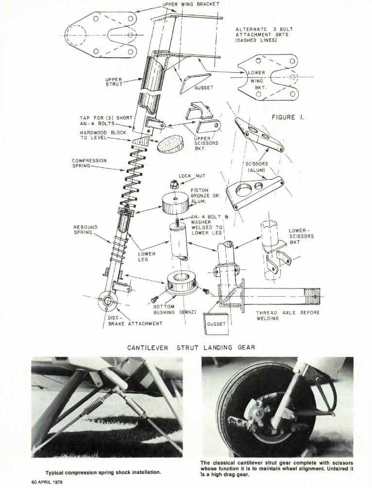
Cantilever Strut Landing GearsThe cantilever or strut type of
landing gear is one of the finestlanding gears around and is ideallysuited to low winged aircraft. Theyare rather heavy but are virtuallymaintenance free. There are manykinds of cantilever strut gears.
Homebuilders being an enterpris-ing lot, find the idea of modifyingand installing a landing gear sal-vaged from some production aircraftvery attractive. The inducementusually stems from some reasonablecost for a salvaged gear and fromthe realization that much work andconstruction time will be saved.
Those featuring hydraulic shockabsorbing units (Aerol, oleo spring,pneumatic, or whatever) are rarelyused in homebuilts. The PazmanyPL-1 and PL-2 designs do featuresuch a gear. However, hydraulicshock struts, if found on ahomebuilt, more than likely, wouldhave been cannibalized from someproduction aircraft and adapted foruse by the builder. Such gear unitsare more complex to build and re-quire some machine shop work. Inaddition, the gear is somewhat fussywhen compared to the simple slabspring gear or the whip gear, anddoes need more care and mainte-nance than most others. Therefore, ifa cantilever strut gear with a hy-draulic shock feature is desired, mostbuilders will try to salvage a land-ing gear from some aircraft ratherthan undertake building one fromscratch. This strikes me as being amatter of good judgement providedthe gear selected is not too heavy. Inaddition, in the event of some futuregear damage a similar replacementgear can often be found.
Other kinds of cantilever strutshock absorbers are more frequently
installed in low wing homebuilt air-craft than are the oleo types. Manylanding gears of this type now in-corporate a coiled compressionspring for the shock absorbing ele-ment of the gear. It makes an excel-lent gear and absorbs the lessershocks of taxiing over the roughground as efficiently as it does theoccasional hard landing. Landingshocks are dissipated smoothly with-out tossing the airplane back intothe air as is characteristic of sometypes of landing gears.
The main load carrying compres-sion springs used in cantilever strutgear legs vary quite a bit but, sur-prisingly, the results obtained seemto be equally good. One gear Iexamined, recently, got by very wellusing a 9" compression spring madeof 15 coils of .344" diameter wirewhile another two seater usinglarger gear legs depended upon abigger spring almost 18" long andmade of 26 coils of .356" diameterwire. The latter, of course, was aheavier landing gear although bothaircraft were in the 1500 poundgross weight category. Rubber puckscould probably be substituted ineither gear with some savings inweight. The longevity of rubberpucks, however, may be somewhatlimited compared to that of the com-pression springs.
These vertical strut landinggears require the installation of ex-ternally mounted scissors or splinesto keep the axle and the lower gearleg from swiveling around inside themain strut. This requirement contrib-utes to a rather aerodynamicallydirty installation. Most Europeandesigners now cope with this prob-lem by encasing the entire gear legand scissors in large bulbous wheelpants which lend a unique appear-
A rigid tripod gear being fitted to a Volksplane 1. Is this animprovement over the original rigid aluminum slab gear?
58 APRIL 1979
The high vertical e.g. of a biplane coupled with the high land-ing speed and relatively narrow gear combine to make thistype of airplane pretty frisky on the runway.

STATIONARYUPPER STRUT
UPPERFLANGE
ALUMINUMSPACERS
X/ (2024 T-3)
EXPLODED VIEW D E T A I L S -
ANBOLT
RUBBERDISKS(SHOCKABSORBERS)
REBOUNDSPRINGS
SHOCK STRUT~-(SLIP-FITS INTOUPPER STRUT)
REINFORCEMENTGUSSETS
FIGURE 3.
VERTICAL SHOCK STRUT(FOR ULTRA LIGHT AIRCRAFT)
#••
A variation of the old J-3 Cub gear complete with bungeecords hanging out in the slipstream. Axle treatment for the welded tube tripod gear installation.
SPORT AVIATION 59
UPPER WING BRACKET
ALTERNATE 3 BOLTA T T A C H M E N T BKTS(DASHED LINES)
TAP FOR (3) SHORTA N - 4 BOLTS
HARDWOOD BLOCKTO LEVEL UPPER
SCISSORS8KT.
COMPRESSIONSPRING SCISSORS
(ALUM)
PISTONBRONZE ORALUM.
AN- 4 BOLT 8WASHER !
REBOUNDSPRING
WELDED TO'iLOWER LEG LOWER -
SCISSORSBKT
BOTTOMBUSHING (8RNZ)
DISC - \BRAKE ATTACHMENT
T H R E A D AXLE BEFOREWELDING
CANTILEVER STRUT LANDING GEAR
Typical compression spring shock installation.
60 APRIL 1979
The classical cantilever strut gear complete with scissorswhose function it is to maintain wheel alignment. Unfaired itTs a high drag gear.

WING ATTACHMENT BKTS.
AN 4 BOLT -W A S H E R 8 /COMPRESSIONSPRING
REBOUNDSPRINGBKT
REINFORCEMENTGUSSET
EXPLODED VIEW
HARDWOOD BLOCKMTO LEVEL)
SCISSORSA S S Y .
MAIN COMPRESSIONSPRING
.090 4130 STL.(WELD TO LEG)
DISC - BRAKEATTACHMENT(4130) SLIP-FIT INTO UPPER LEG
AXLE SIZETO SUITWHEELS
(MACHINED !8
FIGURE 2.
CANTILEVER STRUT LANDING GEAR(A VARIATION)
This Skybolt gear has its bungee hidden inside the fuselageand the landing gear V's are being covered with aluminuminstead of fabric.
Ever see a streamlined "Cub" gear?
SPORT AVIATION 61

ance to the aircraft. Although thecantilever strut landing gear utiliz-ing compression springs or rubberpads is simple in its design andexecution, it is difficult to build. Atleast two pieces must be machined.One is a piston-like cap for the lowerleg and the other is the lower bush-ing. In addition, the welding of thescissor attachment brackets cancause severe distortion in the lowermain strut area and make it dif-ficult, if not impossible, to insert thelower leg with its slip-fit piston. It issuggested, though, that theheliarced elements be torch-heatedto a dull red condition to stress re-lieve the area.
A simpler version of the can-tilever strut gear leg may be madeusing a larger size of tubing for theupper leg and a smaller tube whichfits easily inside that tube. This re-moves the need for machining ofbushings or pistons as the inside ofthe tube becomes the bearing sur-face. The lower leg simply has alarge washer welded to the top of
the lower leg and the main compres-sion spring rides on it. The reboundelement in such an installation isusually a small compression springor rubber bumper added to asplined-like set up. Figure 2 shouldclarify this verbage for you.
The Tapered Rod Or Whip GearThe most attractive feature of
the rod gear is in its simplicity.Even the installation can be simplewith a sleeve welded into the lowerengine mount. However, mounted inother installations complexity of in-stallation increases. The gear islight in weight but is also found bysome builders to be too flexible fortheir aircraft. The flexibility oftencauses excessive wing wobbling dur-ing ground operations and some-times during take-off and landing, arapid cycling of toe-in, toe-out, andcamber occur. This induces a run-way control problem and excessivetire wear. The round rod spring gear
has quirks that many builders donot like. There is very little stabilityin the gear legs because they willflex erratically in all directionswhile, at the same time, they willtwist on all but the smoothest ofpavements. This produces a ten-dency to shudder torsionally withthe vibration being transmittedthrough the entire airplane. In someinstallations, it proves to be verystiff during taxiing and provides arather rough ride. Mechanically thegear would seem to be a great solu-tion to the homebuilder's landinggear problem. Undoubtedly a lot ofthe reported problems stem fromgear legs that are mismatched to theaircraft's weight. Improper designand installation could account foradditional difficulties. The gear legsshould be faired to reduce drag.This, in itself, can be a challengingeffort because the gears flexibilitymakes the accommodation of a fair-ing difficult.
CONGRESSIONAL RESPONSE . . .(Continued from Page 38)I appreciated hearing from you on this important issue.Best regards.
Sincerely,John GlennUnited States SenatorWashington, DC
Mr. R. W. Manetta2519CrawfordTerre Haute, IN 47803
Dear Mr. Manetta:Thank you very much for contacting me regarding your objections
to the proposed FAA right-of-way regulations.As Chairman of the Transportation Appropriations Subcommittee, I
have done what I can to make sure that adequate safety precautionsare considered for air traffic. The alternatives that you brought to myattention appear to be most reasonable, and I have asked the FederalAviation Administration to take a serious look at the EAA's alternativeplans. As soon as I receive a report on this matter, I will be back intouch. In the meantime, I trust you will feel free to let me know if thereis anything further I can be doing to help.
Again, thank you for keeping me posted.Sincerely,Birch BayhUnited States SenatorWashington, DC
Federal Aviation AdministrationOffice of the Chief CounselAttention Rules Docket AGC-24800 Independence Ave., SW 'Washington, DC 20591 •
Re: NPRM Docket Number 18605Notice Number 78-19 , .
Gentlemen:I write to advise you of my strong objection to the FAA proposal to
massively extend positive control of United States airspace. It's an ob-vious over-reaction to the mid-air collision over San Diego, Californiaand in my opinion as a former military pilot and the holder of commer-cial, multi-engine and instrument ratings, it will simply create a horriblyexpensive bureaucratic nightmare.
The function of the FAA is not to create jobs for bureaucrats andexpense for aviation, whether it be general or air carrier. Its majorreason for existence is to structure air traffic so that it provides as safeas possible climate for airspace users. The proposed plan fails misera-bly to accomplish additional safety for those users.
The creation of the new Terminal Radar Service Areas is an absurdfait accompli if they are to be used to prohibit general aviation flight in62 APRIL 1979
the future without positive control. Safety of flight in its most basiccomponent is dependent on the ability of pilots and passengers to seeand to be seen. The FAA proposal will not further that possibility.
The Terminal Control Areas function like a sod covered landing fieldin the jet age. The FAA should recognize the efficiency of climb anddescend corridors that the military used. Simply making those cor-ridors prohibited areas would increase Terminal Control Areas effi-ciency for safety purposes many fold without additional bureaucracyand expense.
Both aircraft at San Diego were under positive control. To the ex-tent that the FAA would put some of the airport trust fund money into"Reliever" airports in major cities accomplished separation could bemade without the incumbent bureaucracy and expense inherent in theFAA plan.
Probably the only word to describe the proposed positive controlairspace restriction is "absurd" unless, of course, the objective is tocreate jobs for the bureaucracy and add expense to the hundreds ofthousands of VFR pilots who fly in these areas.
I fully support FAA proposals that will sensibly enhance aviationsafety and I urge you to carefully consider the positive and sensible re-sponse to the proposed changes made by the Experimental Aircraft As-sociation of Hales Corners, Wisconsin.
Very truly yours.Norman E. GaarU. S. SenatorState CapitolTopeka, KS66612
From: Ray Arvin. Director, Aviation DivisionKansas Department of Transportation
House Resolution No. 6020By Representatives Ferguson and D. Heinemann2-15
A RESOLUTION relating to the Federal Aviation Administration's prop-osed increase in the national airspace in which air traffic control is re-quired.
Be it resolved by the House of Representative of the State of Kansas:That the House of Representatives finds that the recently announcedprogram of the Federal Aviation Administration to drastically increasethe national airspace in which air traffic control is required (proposed"controlled visual flight" rules, 44 Fed. Reg. 1322-33, January 4, 1979)is not in the best interests of the people of Kansas; and
Be it further resolved: That the House of Representatives believesthat this program will adversely affect general aviation and is being fos-tered in apparent disregard of the importance of general aviation to thenational interest and the interest of the people of Kansas: and
Be it further resolved: That the Chief Clerk of the House of Rep-resentatives be directed to send an enrolled copy of this resolution tothe Federal Aviation Administration for inclusion in the record of itsproceedings relating to the proposed visual flight rules.