the static behavior of historical vaults and cupolas
TRANSCRIPT

Wiadomości Konserwatorskie • Journal of Heritage Conservation • 32/2012 65
NAUKA SCIENCE
Praca dopuszczona do druku po recenzjach Article accepted for publishing after reviews
1. INTRODUCTIONMasonry is the main material mankind has exploited to
provide itself a shelter.
Fig. 1. a) Beam requires compression/tension stresses to be resisted; b Curvature of the beam does not help by itself to cancel tension; c) If the eccentricity e is large No-Tension equilibrium cannot subsist
Homes, temples, offi ces, markets and so on are built by some kind of masonry since the beginning of civilization. Walls are the main way loads are transferred to foundations and to underlying soil, but horizontal fl oor structures require some more skill, since masonry, due to its very poor, unreliable, in-homogeneous and time-degrading, tensile strength, is not able to resist bending moments. This is the reason why masonry buildings are often complemented by wood or, more recently, steel systems to cover spaces, providing beam elements resist-ing by pure fl exure.
In a simply supported beam, equilibrium is sustained by bending moments, which in turn require that compression stresses are coupled with tension (Fig. 1a); so if some beam has ever been attempted it is soon realized that failure is inexorable.
On the other side, early ante-literam architects learned from nature that it is possible to overpass empty spaces by stones: natural arches are encountered everywhere in the world (Fig. 2).
a) b)Fig. 2. Natural Arches: a) Capri (Italy); b) The “Elephant Arch” in Pantel-leria (Italy)
Fig. 3. a) True arch: the action of the thrust force H increases the normal force and mitigates the bending moment. A small eccentricity e = M/N results; b) The same happens for a beam with horizontally contrasted suports, thus resulting in an architrave; c) The eccentricity is small and the center C of the normal force is in the interior of the cross-sections
So, the fi rst character that is acquired at glance is that the masonry should be “curve”. If one consider a curved beam (the pseudo-arch in Fig. 1b) one fi nds that the only difference is the insurgence of a compressive normal force on the cross-section, which mitigates, but does not cancel, the need for tension (Fig. 1b). The bending moments remain the same, the normal force is small, the eccentricity is large and the center of the force is
Alessandro Baratta1, Ottavia Corbi2
1 Full professor, University of Naples „Federico II”, Italy, Dept. of Struct. Eng.ng, email: [email protected] Assoc. professor, University of Naples „Federico II”, Italy, Dept. of Struct. Eng.ng, email: [email protected]
The static behavior of historical vaults and cupolas
Zachowanie statyczne historycznych sklepień i kopuł
Keywords: Masonry behaviour, Masonry vaults, Structural assessment, No-Tension model
Słowa kluczowe: statyka elementów murowanych, murowane sklepienia, ocena konstrukcyjna, model beznaprężeniowy

66 Wiadomości Konserwatorskie • Journal of Heritage Conservation • 32/2012
generally out of the cross section (Fig. 1c): equilibrium cannot subsist unless tension is resisted where it is necessary in the structure. If the system is horizontally fi xed at both ends, a new entity is born, the horizontal thrust H, which drastically changes the static regime and a true arch is realized. The thrust force is the key for the arch statics. It acts, in fact, producing larger compressive normal forces and strong counter-moments (Fig. 3a), thus mitigating the fl exure and enhancing compression. The effect is quite independent on apparent curvature: the important fact is that a horizontal force exists able to produce counter-moments with respecto to active load. The architrave is nothing else than an arch with the appearance of a beam (Fig. 3b). The typical condition is a composite compression-fl exure stress, where the compression is large and the fl exure is small, so that the eccentricity with respect to the central line is strongly reduced and the center of force enters in the interior of the cross section: equilibrium is now possible by purely compressive stresses (Fig. 3c).
So, Man learned that it was possible to cover spaces with stones. Anyway, he found and inhabited also large caves, so the attempt to reproduce nature (a strong impulse in Architecture, as testifi ed also in recent times by the Gaudì’s opera, see e.g. [1]) may be has pushed to realize double-curvature roofs. This activity gradually resulted in a success, with larger and larger spans being covered, thus leading to the early architecture and to its developments up to our times.
The historical development of Structural mechanics is exhaustively reconstructed in the book by E. Benvenuto [2]. A very interesting and complete historical survey on the conception, realization and progress in the masonry vaults technology can be found in [3] and in [4, 5]. Here an observa-tion by Thomas Young is reported, namely: “The construction of the dome is less diffi cult than that of an arch since the tendency of each arch to fall is counteracted not only by the pressure of the parts above and below but also by the resistance of those which are situated on each side…..”. That double curvature surfaces are easier to be built than simple arches or barrel vaults is a fact that will receive further specifi cation in the sequel.
2. THE MASONRY AS A MATERIAL
2.1. Overall properties
Masonry is not properly a “material” in the strict sense of the word. It consists in the (generally man-made) assemblage of a basic component (the stones) simply laid on each other or, more often, jointed by mortar. Stones and mortar may have very variable mechanical properties, and the way in which the stones are organized in the masonry volume may (the masonry “texture”) may be very different, and is subject to the skill and the creativity of the designer and/or of the builder.
So, “masonry” has not a uniquely defi ned object, and it is very diffi cult to set up a mechanical model able to closely reproduce the properties of masonry, fi tting all the possible variety of masonry assortment and texture.
Anyway, in all structural analyses the engineer is forced to balance the trend to reproduce the material (and conse-quently the structural behaviour) as closely as possible, with the practical manageability of the analytical tools. Linear theory of structures applied to steel, reinforced concrete and even to masonry, is a successful example of such effort. In all cases the basic theory should include the major features of the behaviour, possibly neglecting many details that poorly infl u-
ence structural safety assessment, and/or are uncontrollable. The small tensile strength in concrete, for instance, not only yields a poor contribution to the structure performance, but since it is a highly uncertain parameter in the concrete mass of a building, it increases uncertainty of the analysis’ results: so it is preferred to adapt linear theory by neglecting tensile strength rather than to exploit cumbersome procedures yielding results depending on uncontrollable parameters.
The fi rst step is then to identify the major properties, that are more or less common to all masonry types. The basic knowledge can be achieved through simple experiments. Uni-axial compression/tension tests can be performed on some Representative Volume Element (RVE) of a typical masonry (Fig. 4).
After some experiments, it is possible to conclude that (Fig. 4a): i) the masonry has different elastic moduli in ten-sion (Et) and compression (Ec); ii) the masonry has different limit stresses in tension (t) and compression (c); iii) the limit stress in tension is much smaller than the limit strength in compression (t << c); iv) the behaviour at failure in compression has some degree of ductility; v) the behaviour at failure in tension is defi nitely brittle, so tensile strength cannot be recovered absolutely.
Fig. 4. a) A typical test of compression/tension on a masonry speciimen; b) The limit strength in compression is intermediate between the strength of mortar (small) and the strength of the bricks (large)
Fig. 5. Synthesis of biaxial tests on masonry prisms. Limit domain (see e.g. Hegemier [6] and Page [7]
Moreover, surprisingly (Fig. 4b), the limit strength in compression of masonry is larger than the strength of the weak element (the mortar) and is bounded from above by the limit strength of the strong component (the stones); this is due to some complex phenomenon of stress interaction and trans-verse deformation of mortar with respect to stones. It is also easy to understand that if the axis of the stress is rotated by an angle, say 90°, the results of the experiment may signifi cantly change, in particular as regards the tensile strength. Some similar conclusions can be drawn from biaxial tests (see e.g.

Wiadomości Konserwatorskie • Journal of Heritage Conservation • 32/2012 67
[6, 7]). Experimental limit strength domains are of the type in Fig. 5, showing a high capacity in compression and a very poor limit in tension without ductility.
Summing up, masonry is a non-linear material, strongly hetero-resistant, anisotropic with respect to tensile strength, with compliance coeffi cients depending on the orientation of the stress axes and different in compression and tension, and with brittle failure at the tension threshold.
2.2. Infl uence of the texture on masonry properties. The case of the masonry wall
The infl uence of the texture on the masonry performance can be illustrated by the following example. Assume that a panel is built by regular bricks with interposed poor mortar joints, lacking any adhesive power. Consider that bricks are set according to the following two patterns (Fig. 2.3a and 2.3b)
Fig. 6. Masonry element: a) Aligned bricks; b) Staggered bricks; c) Free lateral expansion for both panels
If there is no vertical compression both panels are free to expand laterally without encountering any resistance (Fig. 6c).
If a vertical compression is applied, the panel in Fig. 6a still can freely separate; by contrast an horizontal tensile pseudo-strength becomes active in the panel in Fig. 6b, because of friction and interlocking of bricks with each other. The failure mechanism in Fig. 7b can be studied for the bi-dimensional masonry plane element in Fig. 7a having a friction coeffi cient f, a joints stagger s (Fig. 7c) and a row density defi ned as the ratio between the number of block rows in the panel height H and the height H. In Fig. 7 = 7/H.
a) b) c)
Fig. 7. Masonry element: a) Geometrical dimensions, b) Failure mechanism under compression and limit tensile forces, c) Stagger parameter
The wall is subjected to vertical compression stresses y orthogonal to the joints direction and horizontal tractions x parallel to the joints. It is possible to prove [8] that the hori-zontal tensile strength 'ox is given by (Fig. 7b)
(1)
The ratio between the compressive stress on the joints and the transverse tensile strength is
(2)
If the length of the stone is a, s is of the order a/2. Usually a > 2h (very often a > 4h), with h the thickness of the brick, and so s > h. On the other side, ≈ 1/h, so that s > 1 (very often s > 2). With the help of mortar and/or of roughness of the interface between stones, f may possibly be rather large (f = 0.5÷0.8), and the ratio in Eq. (2) is frequently larger than 1, i.e. the tensile strength in the direction parallel to joints is larger than the acting compressive stress.
It can be also proved that a pretty ductility is associated to the tensile strength 'ox . With reference to the diagrams in Fig. 8, applying a safety coeffi cient to the limit resistance 'o, the loss in strength is balanced by a gain in ductility. In other words if 'a is the admissible stress and a is the maximum ductility, one can write
(3)
a) b)
Fig. 8. a) Stress vs. deformation in the tension range, b) conventional diagram with variable ductility
A fundamental observation is that Eq. (1) not only express-es the tensile resistance of the masonry element, but also puts to evidence that the tension can be contrasted in function of the static needs by means of a skilled orientation of the texture of the masonry blocks and of the mortar joints. After recognizing that by the combined effect of compression and friction the lines of the mortar joints are probably the lines where original designers and builders intended to provide tensile strength in the masonry mass, it can be conceived that a technical prac-tice had spread out, very similar to the modern technology of reinforced concrete where the structural designer inserts steel bars in way to balance tension along stretched lines.
Many examples proving that clever architects were aware of this effect when designing vault structures can be illustrated.
3. MASONRY TEXTURE AND APPARATUS IN VAULT STATICS
3.1. The cantilever stairs
In the static analysis of a vaulted staircase, like in Fig. 9, it is possible to recognize three basic typological components: the landings, the angle connections, and the fl ights of stairs (two or three depending on the structure morphology). The structure is supported by the outside walls system which represents the stairs box.
Looking at the section of a vaulted stair in Fig. 10a, such structural conformation suggests an apparent paradox: despite the fact that masonry is not effective in sustaining tension

68 Wiadomości Konserwatorskie • Journal of Heritage Conservation • 32/2012
stresses and bending, it should work as a cantilever, or however it is an incomplete vault which lacks the counter-thrust from the missing part of the arch (Fig. 10b) and so being prone to lose the equilibrium state (Fig. 10c).
a) b)
Fig. 9. Vaulted stairs: a) Planimetric view; b) Longitudinal section
It is quite obvious that the solution of the contradiction goes pursued abandoning the search of improbable plane pat-terns and by investigating three-dimensional equilibrium paths accounting for the space articulation of such structural organ-isms, searching stress fi elds in equilibrium and compatible with the resistant abilities of the masonry material as usually interwoven in the case of “cantilever” stairs.
a) b) c)
Fig. 10. Transverse sections of vaulted stairs: a) Section and particular of one step; b) “Half barrel vault” model, c) Improbable “cantilever” behaviour
a) b)
Fig. 11. Comparison of tension isostatic lines with the mortar rows. a) Tension lines calculated by a FEM (linear) procedure; b) Mortar rows in the fl ights
After identifying the basic internal force distributions through which the stairs can equilibrate their own weight and live loads, and the correlation that was intended by the original builders between statics and masonry tissue, it is also possible to design the reinforcement of the vaults, that shall be designed in way to sustain the possible equilibrium paths. Apart from complex analyses (see e.g. [9]), it is possible to identify simplifi ed equilibrium patterns that are compatible with the load-carrying capacity of the structure [10]. All these approaches, FEM and/or simple 3D-beam, agree in identify-ing isostatic tension lines that approximately agree with the proceeding of the rows of mortar joints (Fig. 11), that are com-pressed in the orthogonal direction, thus developing a tension capacity along their lines of action; thus proving that the statics of these stairs are strictly connected with the vault apparatus. It is also possible to use this argument in an inverse fashion,
i.e. to infer isostatic lines proceeding from the observation of the masonry texture. Any double curvature cover, in fact, is a highly hyperstatic system, which means that it can select its own pattern in a large set of possible equilibrium paths. So texture and vault apparatus are a tool by which, apart from the shape of the vault (barrel vault, rib vault, groin vault, etc.) the architect can steer the structure to work in some preferred way.
3.2. Tension in spherical domes
Consider the axial-symmetric hemispherical dome with radius R and thickness t (Fig. 12a), supporting its own weight w, where it is well known that in the classical solution, tension should be active along the parallel lines after some degree of the zenith angle .
Here the meridian stress N and the hoop stress N are [11]
(4)
with w = t and the unit weight of the material constituting the shell.
The ratio is
(5)
a) b) c)
Fig. 12. a) Spherical dome; b)Ratio of parallel to meridian stress resultant. Nj is everywhere compressive for any j, and Nq is a tensile stress for j > 51.8°; c) The friction pattern yields a admissible stress if fsw > 1
The ratio is plotted in Fig. 12b, whence one can see that the ratio is always not larger than 1. So, if masonry is organized by staggered regular bricks –as often happens tension could generally be faced by the friction mechanism as illustrated in Sec. 2.2 (Fig. 12c).
Anyway, equilibrium can be found by some other mem-brane surface other than the mean surface of the shell, pro-vided it is included in the thickness between the (spherical) intrados and extrados. Considering a revolution membrane surface having an elliptic profi le with radii a and b, included in the interior of the hemisphere (Fig. 13a) the internal forces equilibrating the weight of the spherical dome can be found by the following procedure
a) b)
Fig. 13. a) The elliptic membrane surface included in the dome thickness; b) Possible physiological fractures in the masonry

Wiadomości Konserwatorskie • Journal of Heritage Conservation • 32/2012 69
Consider the spherical cap above the center angle whose weight is
(6)
The angle is related to the zenith angle by the rela-tionships
(7)
The radii of curvature of the ellipsoidal surface are ([11], p. 40)
(8)
so that
(9)
and
(10)
The equilibrium versus the vertical translation can be written
(11)
and
(12)
The ellipsoidal membrane shall now sustain the weight w of the spherical shell, that transforms in the weight w* on the ellipsoid setting
(13)
whence
(14)
The equilibrium along the outward normal to the (ellip-soidal) membrane yields
(15)
and
(16)
Ellipsoidal stress surface can be active in order to mitigate tension hoop stresses, possibly after some fractures have opened (Fig. 13b), that can be considered physiological if masonry has some degree of ductility in the parallel direction, as in the fric-tion strength mechanism illustrated in Sec. 2. In Fig. 14a various membrane stress surfaces are plotted, with different ratios a/b. Note that such surfaces make sense provided that they remain included in the thickness of the spherical shell, i.e. if t ≥ 2(Ra) and t ≥ 2(bR), with b ≥ a. The plots in Fig. 14b prove that the ratio of the parallel to the meridian normal force can be mitigated, and also be near 0.4 and smaller, with increasing the ratio b/a. Consider that both in the spherical and in the elliptic membranes, the stress surface is a complete semi-ellipsoid, with = 90° at y = 0, so that the equilibrium solutions do not require any thrust force at the bottom support y = 0.
a) b)
Fig. 14. a) Ellipsoidal membrane surfaces for different ratios of the ellipse radii a and b to the radius R of the spherical dome; b) Ratio of Nq to Nj for different shapes of the elliptic profi le
Anyway, it has been proved by [12] that a membrane surface included in the thickness of the dome can be found without hoop tension, provided that a adequate counter-thrust force can be exerted at the bottom of the dome. In Fig. 15a it is illustrated how the spherical and elliptic membranes only transfer vertical actions on the basement, vs and ve respectively, while a no-tension profi le requires that the base support can support a horizontal force hn (Fig. 15b).
a) b)
Fig. 15. No-thrust and no-tension stress surfaces: a) The basement of the dome is not subject to thrust action, but lower parallel lines are under tension; b) If a no-tension solution is adopted, the support of the dome is subject to a horizontal thrust force. Tension in the parallel lines is trans-ferred to the basement
3.3. The effect of “masonry apparatus” on the statics of vaults. An help to intuition.
Reading masonry texture in a vault can help in under-standing its equilibrium asset. The fi rst element is indeed its geometry, a cross vault yields a equilibrium pattern different than a barrel vault, and so on. But a double-curvature sur-face, apart from its particular conception is anyway a highly hyperstatic system, and the equilibrium is never uniquely determinate. So the way the stones are jointed all together is a key to understand what equilibrium path would stresses run through, and/or what path would the builder have preferred to drive the vault to accommodate in.

70 Wiadomości Konserwatorskie • Journal of Heritage Conservation • 32/2012
So, consider for instance the two vaults in Fig. 16a and in Fig. 16b, having the same geometry, but in vault a) the mortar rows are parallel to the base perimeter, while in the vault b) the mortar rows are normal to the perimeter. The postulate is that compression normal to the mortar rows is the preferred equilibrium path for the vault, and that this is the tool for the original builder to steer the vault into a (his) objective static asset. If the preferred direction for compression is normal to the perimeter, it is expected that compression acts along the arrows drawn in Figs. 3.8, a) and b), so that the vault gains a tensile capacity in the direction orthogonal to the arrows. It is easy to understand that this produces an effect on the thrust the vault exerts on the base supports. Consider in fact that in both cases the vault is made by four gores. In the case a) compres-sion is directly transferred to the sides of the basement, while lateral dilatation and the diffusion of stresses to the corners is contrasted by internal tensile strength; so two opposite gores tend to directly sustain each other, and the distribution of the horizontal thrust force tends to concentrate towards the middle of the sides (Fig. 16c). By contrast, in case b) compression is active in the direction parallel to the base sides, and the gores tend to support each other along the diagonal lines, while the orthogonal dilatation and diffusion of stress are now contrasted by tensile strength in the direction orthogonal to the sides; so all forces tend to converge in the corners, and the distribu-tion of the horizontal thrust force tends to concentrate to the corners (Fig. 16d). In other words, by acting on the masonry apparatus it is possible that, with the same geometry, a structure may be realized that works like a cloister vault rather than like a groin vault or viceversa. Which means that it may be not wise to analyze the statics of a vault only on the basis of its geometry. Anyway, a skilled design of apparatus is also a tool to build vaults without formworks [13].
Fig. 16. Infl uence of the vault apparatus on the static behaviour of vaults. The difference in the apparatus in Figs. a) and b) yields a different equi-librium pattern and a different distribution of the thrust force as in Figs. c) and d)
4. MASONRY AS A NO-TENSION MATERIAL
In the previous section it has been recognized that in some cases a tensile capacity along some direction can be attributed to masonry. Anyway Eq. (1) is conditioned by the implicit as-
sumption that 'ox is not larger than 'ob, the tensile strength of single bricks. If in any time in the life of the structure the stress s exceeds this limit, the bricks crack, and the strength decays to zero, with a brittle behaviour. On the other side, there is no doubt that the prevalent feature that characterizes masonry structures, and makes them dissimilar from modern concrete and steel structures, is quite defi nitely their intrinsic inability to resist tensile stresses. So, it is natural that the material model, that is intended to be an “analogue” of real masonry, cannot resist tensile stress, but, possibly, behaves elastically under pure compression.
No-Tension solutions for masonry structures are how-ever a very signifi cant reference point and a powerful tool for reliable structural assessment, for many reasons. The fi rst reason is that the NT model is a stable behaviour, poorly subject to uncertainty and aging. Tensile strength is in any case small, uncertain, highly variable in the mass of a structure, not durable in time and so on; anyway neglecting tensile strength leads to a safe assessment. In other words, no doubt that the NT model is a simplifi ed behaviour, that in some cases does not give account of some surprisingly good performance of masonry buildings, but it is also true that if a masonry structure does not pass through a NT check it remains a suspect structure.
In the following the basics for the foundation of a NT material theory are illustrated, and the relevant principles for structural analysis, mainly identifi ed in the classic energy theo-rems, suitably adapted to the material at hand, are formulated.
In (apparently) simple cases, closed-form solutions can be obtained, or, at least, the solution process can be prepared after a preliminary screening of the equilibrium scenario.
4.1. The standard No-Tension material
In a NT solid the equilibrium against external loads is required to be satisfi ed by admissible stress fi elds, which imply pure compression everywhere in the solid. Compatibility of the strain fi eld can be ensured by superposing to the elastic strain fi eld an additional fracture fi eld, that does not admit con-traction in any point and along any direction; that is to say that the stress tensor must be negative semi-defi nite everywhere in the solid, while the fracture strain fi eld f is required to be positive semi-defi nite.
The material shall, hence, satisfy the following conditions
(17)
where ra is the set of directions through the generic point in the solid, a is one of such directions, f is the fracture strain that is assumed to superpose to the elastic strain e in order to anneal tensile stresses if possible, and C denotes the tensor of elastic constants. Consider moreover that on every elementary surface with normal a, if fa is strictly positive a must be zero; by contrast if a is strictly negative, fa must be zero. If o is the stress tensor in the point actually associated with fractures f, it follows that
(18)
Wiadomości Konserwatorskie • Journal of Heritage Conservation • 32/2012 71
The material admissibility conditions for strain and stress reported in Eq.(1) can be synthetically referred to by the set of inequalities h(f ) ≥ 0 and h() ≥ 0 respectively.
As a consequence of Eqs. (17) and (18), the classical Drucker’s rule holds for the fracture strain. With reference to the admissible domains quoted in Eq. (4.1), the normality Drucker’s law for no-tension material can thus be written as
(19)
where is the set of admissible stress tensors and is any admissible stress state other than the effective one o.
4.2. Limit Analysis and fundamental theorems
Let consider the body and surface forces, F acting on vol-ume V and p acting on the free surface Sp, the displacement fi eld u, the imposed displacement fi eld uo characterizing the constrained part of the solid surface Su, the above mentioned strain fi eld = e + f = C + f, the stress fi eld .
As clear from the above, fracture strains f can be devel-oped at the considered point only if the stress situation can be represented by a stress tensor laying on the surface of the material admissibility domain, which is defi ned for NT bodies by h() ≤ 0; obviously if some fracture does exist, it is developed according to the NT material inequalities h(f ) ≥ 0.
4.2.1. General setup
Denoting by U the set of possible displacement fi elds, the class of fracture admissible mechanisms is defi ned by the subset Uf of U containing displacement fi elds uf that are directly compat-ible with fracture strains f apart from any elastic strain fi eld
(20)
(21)
Collapse mechanisms can be defi ned as fracture admissible mechanisms uf such that the mechanical work developed by the applied loads (p,F) is positive; this condition is analytically expressed by the inequality
(22)
By the Principle of Virtual Work, a necessary condition for the existence of any admissible stress fi eld equilibrating the applied loads is that
(23)
After Eq. (23) one can enounce the “Kinematical Theo-rem” of Limit Analysis for NT bodies: if any collapse mechanism exists under the applied loads, no solution can exist for the equilibrium of the NT solid. In other words: If any collapse mechanism exists, the solid collapses.
On the other side, statically admissible stress fi elds can be defi ned as tensor fi elds equilibrating the applied loads and sat-isfying admissibility conditions, i.e. h() ≤ 0 or , where
is the admissible domain, everywhere in the solid. Assuming that under the load pattern (p,F) a statically admissible stress fi eld exists for any mechanism uf, after Eq. (23) one gets
(24)
One can, thus, enounce the “Static Theorem” of Limit Analysis for NT bodies: if under the applied loads any statically admissible stress fi eld exists, no collapse mechanism exists and the structure cannot collapse.
4.2.2. The one-multiplier load pattern. The safety factor
Let assume the applied loads as given by the sum of a fi xed component (Fo, po) and a variable component (sFv, spv) depending on the value assumed by the multiplier s (actually one thus assumes that only the portion Fv, pv, may be desta-bilizing and should be controlled)
(25)
and let defi ne two fundamental classes of load multipliers s for NT bodies: the class of statically admissible multipliers and the class of kinematically suffi cient multipliers . After denoting by n the unit outgoing vector normal to the surface Sp, load multipliers are defi ned to be statically admissible if the fol-lowing relations hold
(26)
(27)
that is to say, if a stress fi eld exists equilibrating the ap-plied loads with s = and satisfying the NT material admis-sibility conditions. A stress fi eld satisfying Eqs (26) and (27) is qualifi ed as statically admissible.
On the other side, load multipliers are defi ned to be kinematically suffi cient if the following relations hold
(28)
(29)
(30)
(with the symmetrical gradient operator), that is to say, if any displacement fi eld u
f exists (a collapse mechanism) directly compatible with a NT admissible fracture strain f apart from any elastic strain fi eld, and such that the condition stated by Eq.(30) is also satisfi ed. It is understood that the body is stable under the basic load pattern (Fo, po), and that Eq. (30) cannot be satisfi ed by any fracture strain fi eld for = 0. In other terms it is assumed that the basic loads are suitably chosen in way that they cannot produce collapse.

72 Wiadomości Konserwatorskie • Journal of Heritage Conservation • 32/2012
Extensions to NT continua of the fundamental static and kinematic theorems of Limit Analysis allow individuating the value s- of the load multipliers s, limiting the loading capacity of the body.
On the basis of the static theorem, one can state that “the collapse multiplier s- represents the maximum of the statically admis-sible multipliers ”
(31)
where Bo is the class of statically admissible multipliers.On the basis of the kinematic theorem, one can state that
“the collapse multiplier s- represents the minimum of the kinematically suffi cient multipliers ”
(32)
where o is the class of kinematically suffi cient multipliers.Thereafter, by means of the static theorem, one can search
for the collapse multiplier by implementing the problem
(33)
Or otherwise, by means of the kinematic theorem, by solving the problem
(34)
4.3. Variational principles for the NT equilibrium problem
Analysis of no-tension structures proves that stress, strain and displacement fi elds obey extremum principles of the basic energy functionals. Therefore the solution displacement and fracture strain fi elds are found as the constrained minimum of the Potential Energy functional, under the condition that the fracture fi eld is positively semi-defi nite at any point. In other words, if and u are respectively the strain and the displace-ment fi elds such that
(35)
and p, F are the surface tractions and the body forces, it is possible to write down the Total Potential Energy (TPE) functional
(36)
with D the inverse tensor of C. The TPE functional E(u, f) is made up by two terms, expressing the energy stored in the body L(u, f) and the opposite of the work made by the applied loads P(u). It can be proved that the solution uo, fo satisfi es the following condition
(37)
which is the minimum of the Potential Energy, conditioned upon admissibility of the fracture strain, with the set of admissible fracture fi elds. Despite the quadratic functional L(u, f) is positive defi nite, the minimum may be not unique if some mechanism exists such that P(u) = 0.
The stress fi eld can be found, in turn, as the constrained minimum of the Complementary Energy (CE) functional, un-der the condition that the stress fi eld is in equilibrium with the applied loads and compressive everywhere. In other words, let
(38)
be the CE functional S () defi ned on the set o of the admissible stress fi elds (o) in equilibrium with the applied loads, with Lc() the complementary energy stored in the body and R() the work by the reactions times the settlements of the constrained points. It can be proved that, if ois the solution stress fi eld, the following condition holds
(39)
Eq.(39) expresses the compatibility condition on the solu-tion stress fi eld, i.e. the constrained minimum of S () yields the stress fi eld o such that the elastic strains Co can be made compatible with a continuous displacement fi eld, by the su-perposition of a fracture strain fi eld. Since · C is positive defi nite in , the solution is unique.
4.4. Convexity of the energy functionals and Limit Analysis as a tool for existence of the solution
It is easy to prove that the Total Potential Energy and the Complementary Energy functionals are both defi ned on convex sets. The respective sets of defi nition are: i) the space of couples (u,f), with u a displacement vector function com-patible with the external constraints and f a semi-positively valued tensor fi eld; ii) the space of semi-negatively valued tensor fi elds in equilibrium with the applied loads. Because of convexity, both minima exist if the respective defi nition sets, U on one side and o on the other side, are not empty. For o to be not empty it is necessary and suffi cient that the structure is under the collapse threshold; in this case a unique minimal point exists for S (). U and are intrinsically not empty, in that the fi rst is the set of three-components vector fi elds and the second is the space of semi-positive defi nite 3rd-order tensor fi elds. The displacement/fracture solution may be not unique if a mechanism exists such that the external work is zero. Anyway, if any collapse mechanism exists, E (u,f) diverges, and the minimum does not exist.
It can be concluded that the solution of the NT equilibrium problem exists iff the structure is under the collapse threshold.

Wiadomości Konserwatorskie • Journal of Heritage Conservation • 32/2012 73
4.5. The NT solution for masonry arches and barrel vaults
NT solutions have been investigated since many years and many results have been produced, also yielding success-ful comparison with experimental results. As an example, consider the portal arch in Fig. 17a, that has been tested under an horizontal force acting on top of the right pillar, as in Fig. 17b. In Fig. 17c the comparison between the experimental and numerical results is plotted, proving a very good agreement of the NT theory with practice.
a) b) c)
Fig. 17. Experimental and mechanical model: a) The laboratory arch-portal tested under the horizontal force F; b) The mechanical NT model for cal-culations; c) Plot of numerical and experimental results
More details on NT material and structures can be found in [14, 15].
5. NO-TENSION MODEL FOR MASONRY – LIKE SHELLS AND DOMES
Equilibrium fi elds for No-Tension vaults can be built upon the assumption that a membrane stress-surface is considered, included in the profi le of the vault, displaying compressive forces along all directions. The idea is not new, it was put forward by Heyman [11], but there are few doubts that it represents a powerful approach to search stresses in masonry vaults, as the 3D direct counterpart of the traditional historical method based on the funicular line of the loads in 2D structural problems (Fig. 18).
a) b)
Fig. 18. a) Arch equilibrium analysis: the pressure line; b) Vault equilibrium analysis: the membrane stress surface
As illustrated in Sec. 4, modelling a large variety of equi-librium stress fi elds is the preliminary step to fi nd a fi nal solu-tion, yielding a credible pattern for the fracture distribution, in agreement with technical expectation, as it can be recognized for the two-span arch in Fig. 19
In the following an approach is outlined to identify mem-brane stress surfaces both responding to the requirements of stress admissibility and equilibrium with active loads.
Fig. 19. Sample results from NT model. a) The arcade and the experimental set up; b) The arcade in the original confi guration and with downward set-tlement of the central pier; c) Pressure line and fractures without settlement; d) Stresses without settlement; e) Pressure line and fractures with settle-ment; f) Stresses with settlement
5.1. Membrane 3D-equilibrium of the generic vault element
Let consider a membrane shell z = z (x,y) subject to ge-neric load components px, py, pz , as shown in Fig. 20. In order to express local equilibrium conditions one should consider any single surface element under the action of loads and of membrane stresses, and write equilibrium equations along coordinate axes, as in Fig. 21.
After some algebra, the equilibrium equations in the x and y directions can be written in the form
(40)
(41)
Additionally, equilibrium along the z-direction yields
(42)
Fig. 20. The membrane surface Fig. 21. Generic surface element of the membrane surface
5.2. Equivalence of the 3D-problem with the projected 2D-problem
Considering the projections Nx, Ny, Nxy = Nyx of the mem-brane stresses onto the xy pIane, as shown in Fig. 22

74 Wiadomości Konserwatorskie • Journal of Heritage Conservation • 32/2012
Fig. 22. Stresses and loads acting on a generic 3D-element of the vault mid-surface and their projec-tion on the plane
Fig. 23. The vault and its mid-surface under purely vertical loads
the following equations hold
(43)
with
(44)
Moreover putting
(45)
the equilibrium equations in function of the new variables can be written
(46)
The z-equation, after some algebra, reduces to
(47)
whence one gets
(48)
So the membrane equilibrium, apart from Eq. (48), be-comes analogous to the problem of a plane panel.
5.3. Reduction of equilibrium conditions by means of the stress function
In most cases, it is advantageous to introduce a stress func-tion (x, y) that reduces the 3 equilibrium equations to one second-order equation as follows. By analogy with the panel problem, the equilibrium conditions in the x and y directions are identically satisfi ed if one puts
(49)
Then the third equilibrium equation (48) turns into
(50)
The solution of the problem is, thus, reduced to the determination of the stress function. If px = py = 0 (e.g. the vault sustains only gravitational loads), the latter equation simplifi es to:
(51)
5.4. Stress NT admissibility
Let consider a masonry vault with thickness s, subject only to vertical loads, as shown in Fig. 23 Since it is assumed that the masonry cannot resist tensile stresses, the internal forces have to satisfy the following admissibility conditions
(52)
A solution can be attempted searching for a membrane surface z = z(x,y) completely internal to the mass of the vault, and such to resist the downward (i.e. positive) load pz by purely compressive internal forces. The fi rst condition is expressed by the inequalities (the inclusion condition)
(53)
where z1(x,y) and z2(x,y) are the surfaces identifying the upper and lower profi les of the vault, respectively.
Defi nitively, setting the problem in plane variables and assuming that only vertical loads act, the equilibrium is ex-pressed by Eqs. (49) with px = py = 0 and by Eq. (51), whilst admissibility conditions are given by
(54)
Eqs. (54) are conditioned by Eq. (53), according to which the stress membrane shell of the vault should be kept within the vault’s profi les.
5.5. Simple coupling of stress equilibrium with admissibility
So, the key of the problem is how the stress function (x,y) combines with the membrane function z(x,y). It is interesting to note that if one takes
x,y = k z(x,y), k > 0 (55)
by substitution in Eq.(49), one gets
(56)
Coupling with admissibility conditions, one gets

Wiadomości Konserwatorskie • Journal of Heritage Conservation • 32/2012 75
(57)
with Hz(x,y) the Hessian determinant of the z function, and X the horizontal projection of the vault. On the other side, substitution of Eq. (55) in the z-equilibrium Eq. (51) yields
(58)
with Q the thrust basement factor. From Eqs (57) one can deduct that z(x,y) is a concave function. One can also observe that in a masonry vault. equilibrium may coincide with admissibility. This result means that a single joint equation is able to account at the meanwhile for both equilibrium and admissibility, also giving a scientifi c demonstration of the easiness of building masonry vaults, due to the almost immediate intuition of equilibrium against applied load, which is able to assure also admissibility.
Eq. (58) represents the simplest form of the well known Monge-Ampère equation [16], and quite clearly plays a key role in the statics of NT vaults [17].
5.6. General coupling of stress equilibrium with admissibility
More in general consider the position
(x,y) = F[z(x,y)] (59)
Eq.s (49) turn to
(60)
and Eqs. (54) yield
(61)
while the z-equilibrium Eq. (51) is
(62)
5.7. Problem solution in terms of stress and fractures by the complementary
energy approachOnce membrane forces have been identifi ed, stresses and
consequently elastic energy can be easily calculated.Therefore, after individuating the set of statically ad-
missible membrane surfaces (in terms of admissibility and equilibrium, i.e. satisfying the set of inequalities in Eqs (40)-(41)-(42) and (52)), a possible approach in order to fi nd the solution in terms of stresses is to set up a Complementary Energy problem to be formulated as a kind of extension to masonry vaults of the classical analogous energetic approach for linearly elastic structures, aiming at fi nding the fracture fi eld that yields a compatible strain fi eld when combined with elastic strains.
In order to undertake this approach the expression of the Complementary Energy embedded in a masonry vault element shall be evaluated. In case of NT assumption, one should con-sider that the generic element appears to be partially resistant; with reference to Fig. 24 one has the following stress and strain components in he membrane’s plane
(63)
where CN is the point where the membrane surface intersects the normal to the middle surface of the vault, u is the distance from CN to the compressed profi le of the vault element, the neutral surface where stresses are null is at distance 3u from the compressed profi le, the part of the vault element below (or above) the neutral surface is inert and possibly fractured, Arx = 3udsy and Ary = 3udsx are the reactive areas of the respective cross-sections, Gr is the centroid of the reactive part of the vault element, er is the distance of the membrane from Gr, and Nx, Ny are the normal forces per unit length on the element edges; mx = x(Gr), my = y(Gr) are the average compression stresses on respectively Arx and Ary
(64)
Eqs. (63) and (64) after some algebra yield

76 Wiadomości Konserwatorskie • Journal of Heritage Conservation • 32/2012
(65)
a) b)
Fig. 24. Cross sections of the generic element of the vault and normal stresses distribution: a) Cross-section xz, b) Cross-section yz
When neglecting the curvatures of the element and the shear stress component, the elementary elastic work is
(66)
and so is the elastic energy stored in the element dL = dLe. The elastic energy over the whole vault is
(67)
where S is the mean surface of the vault. In Eq. (67) all the entities in the integrand function are dependent by the point coordinates through the membrane function z(x,y).
The fi nal Complementary Energy functional S expression is given by adding to the elastic energy term L, the energy related to the work developed by the constraint reactions R, as S =L+R.
The solution in terms of stresses shall be then searched for by numerically implementing the minimization of the Com-plementary Energy functional over admissible z-functions, i.e. under the condition that the solution itself is respectful of the above individuated equilibrium and admissibility equations.
6. SOLUTION OF NT EQUILIBRIUM. THE VAULTS OF TRANSLATION
After membrane forces have been identifi ed, stresses and consequently elastic energy are easily calculated.
As shown in the previous paragraph, a possible approach to the problem consists in hypothesizing a shape of the stress
function (x,y) a priori satisfying equilibrium and material admissibility, and, thereafter, deducing the related membrane function z(x,y), and, therefore, stress distribution; in some cases this approach allows to identify solutions fi tting some vault typologies; in the following, the case is presented of vaults of translation, such as the simple case of the barrel vault with indefi nite length and the -less simple- barrel vault with con-straints at its longitudinal extremities, which requires a rather more complex treatment.
6.1. The indefi nite length barrel vault
Fig. 25. The indefi nite barrel vault and its cross-section
With reference to Fig. 25, consider the stress function in the form
(68)
whence
(69)
From Eq.(51), equilibrium turns into
(70)
If one considers
(71)
Eq. (70) reduces to
(72)
which can be solved with
(73)
whence

Wiadomości Konserwatorskie • Journal of Heritage Conservation • 32/2012 77
(74)
According to Eq. (56) the solution is admissible if – kz(x) +g(x) ≤ 0 . If one takes – kz(x) +g(x) = 0 the previ-ous Eqs (73) yield Ny = 0, and the equation
(75)
yields the funicular line of the active load, with H the relevant thrust, which is the well known solution for the barrel vault as a sequence of independent arches (Fig. 25).
6.2. The confi ned barrel vault
A second case can be obtained setting
(76)
with the coeffi cient a such that 0 ≤ aL ≤ 1, being L a length parameter, and (x) obeying the equation
(77)
One should notice that (x) is the function governing the internal forces in the membrane surface. In fact, from Eq.(49), one has
(78)
o(x,y) is assigned in the form
(79)
with G(x) and Q(x) obeying the following differential equations
(80)
The membrane surface remains identifi ed by the equation:
(81)
The initial values of (x), G(x), Q(x) with the relevant derivatives, and the values of a and k remain undetermined and available to set additional constraints.
In fact, if the problem is symmetric in both directions <x> and <y>, the following conditions shall be added:
(82)
(83)
still because of symmetry
(84)
Initial conditions for (x), G(x) and Q(x) and the param-eters a and k can be sought in order to meet the requirement that the membrane surface z = z(x,y) is in the interior of the vault thickness everywhere. Note that the set functions satisfy the equations
(85)
(86)
with 0 ≤ (y) ≤ 1 for any y, i.e. equilibrium and admissibility vs. vertical load are verifi ed.
If one looks at the z-surface resulting from the above posi-tions, one realizes that this can be assumed as the membrane surface for a confi ned barrel vault (Fig. 26).

78 Wiadomości Konserwatorskie • Journal of Heritage Conservation • 32/2012
Fig. 26. The confi ned barrel vault with a possible membrane surface: a) Axonometric projection; b) Transverse xz section; c) Longitudinal yz section
7. VAULTS OF GENERAL SHAPE. THE MONGE-AMPERE EQUATION
The set S of solutions of the Vault Inequality System (VIS) composed by the inequalities
(87)
with X the horizontal projection of the vault, contains all solutions of the z-equilibrium Eq. (58). Solutions of the system Eq. (87) defi ne convex functions z(x,y) included in the profi le of the vault, and enjoy the following property: If zi(x,y) (i = 1,…,N) are N functions, each verifying the, pos-sibly homogeneous, basic VIS system in Eq. (87), any convex combination of such functions also yields a member of the solution set of the vault inequality with the strict inequality sign. The homogeneous VIS is the same as Eq. (87) with the sign of equality in the fi rst row.
7.1. Finding solutions
It is possible to build up a number N of solutions zi(x,y) (i = 1,…,N) of the homogeneous or non-homogeneous VIS, so that solutions of the z-equilibrium equation
(88)
can be searched in the form
(89)
where each of the basic functions zi(x,y) is assumed to comply with the VIS [Eq. (87)], in homogeneous or non-homoge-neous form.
Assume, moreover, that some coi coeffi cients have been found such that
(90)
verifi es the inclusion condition. To this aim, it is suffi cient that Eq. (90) is a convex combination of the basic zi’s, possibly approaching as much as possible the middle surface zm(x,y).
Coeffi cients ci yielding solutions of Eq. (88) correspond to the minimum of the error function
(91)
with
(92)
One should notice that, since z(x,y| ci) is assumed to be convex, also R(ci) ≥ 0 and because of the Schwarz’s inequality
(93)
The conditions for the minimum of Eq. (91) with respect to Q are written
(94)
whence
(95)
After substitution in the expression in Eq. (91) of the mean square error, one gets
(96)
By virtue of Eqs. (92)-(93), (ci) is a positive defi nite function of its arguments ci and it is null if Hz(x,y) = –pz (x,y).
It follows that the minimum of (ci) is attained where the ratio ~R2(ci)/S(ci) is minimum. Therefore the problem can be defi nitely set in the form
Wiadomości Konserwatorskie • Journal of Heritage Conservation • 32/2012 79
(97)
All load patterns –pz (x,y) such that coeffi cients ci resulting in =0 exist, are called manageable load patterns with respect to the assumed form for the function z(x,y|ci). If the applied load is manageable, equilibrium can be exactly satisfi ed. Otherwise, equilibrium can be approximately verifi ed, to some extent, depending on the choice of the basic functions zi(x,y).
Further details and applications are illustrated in [17, 18]. Interaction with the reciprocal problem, i.e. No-Compression double curvature structures, can give fruitful contributes to new developments (see e.g. [19]).
7.2. Some results. The NT vault subject to the self-weight and to a manageable live load
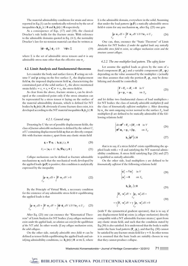
As an example, a parabolic vault covering a rectangular domain X = [x1,x2] × [y1,y2] . The vault is characterized by height f, thickness s and middle surface
(98)
with a = f /(x12 + y1
2).
a) b)
Fig. 27. Sample results: a) Plot of the objective load p(x,y) = w(x,y)+ q(x,y); b) Superposition of the objective load and its approximation by means of Hz(x,y); the two plots are practically coincident
The objective load is composed by the superposition of an accidental load q(x,y) localized around a point (xo, yo) and the self weight of the vault w(x,y) given as follows
(99)
with t denoting the height of the superstructure, f and m the unit weight of the superstructure and of the structural masonry respectively.
A manageable live load is assumed in the form
(100)
and the results are plotted in Fig. 27, proving a perfect agree-ment between the Hessian Hz(x,y) of the function z(x,y) and the objective load p(x,y) = w(x,y)+ q(x,y).
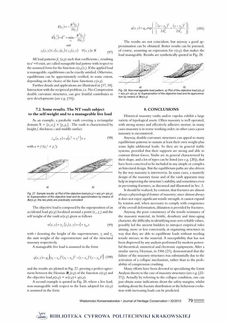
A second example is quoted in Fig. 28, where a live load, non-manageable with respect to the basis adopted for z(x,y) is assumed in the form
(101)
The results are not coincident, but anyway a good ap-proximation can be obtained. Better results can be pursued, of course, assuming an expression for z(x,y) that makes the load manageable. Results are synthetically quoted in Fig. 28.
a) b)Fig. 28. Non-manageable load pattern: a) Plot of the objective load p(x,y) = w(x,y)+ q(x,y); b) Superposition of the objective load and its approxima-tion by means of Hz(x,y)
8. CONCLUSIONS
Historical masonry vaults and/or cupolas exhibit a large variety of typological assets. Often masonry is well operated, with strong stones and effectively adhesive mortar; in many cases masonry is in worse working order; in other cases a poor masonry is encountered.
Anyway, double-curvature structures can appeal to many equilibrium patterns to sustain at least their own weight plus some light additional loads. So they are in general stable systems, provided that their supports are strong and able to contrast thrust forces. Vaults are in general characterized by their shape, and a lot of types can be listed (see e.g. [20]), that have been conceived to be included in any simple or complex architectural design. But the equilibrium paths are also driven by the way masonry is interwoven. In some cases, a masterly design of the masonry tissue and of the vault apparatus may help in improving the structure’s stability, and sometimes even in preventing fractures, as discussed and illustrated in Sec. 3.
It should be realized, by contrast, that fractures are almost always a physiological feature of masonry; since almost always it does not enjoy signifi cant tensile strength, it cannot expand by tension and, when necessary to comply with congruence of the overall deformation, dilatation is provided by fractures.
Anyway, the poor consistency of the tensile resistance of the masonry material, its brittle, desultory and time-aging character, the diffi culty in identifying non-zero reliable values, possibly led the ancient builders to introject empirical rules aiming, more or less consciously, at organizing structures in way that they are able to equilibrate loads without needing tensile stresses in the material. A susceptibility that has not been disproved by any analysis performed by modern power-ful theoretical, numerical and electronic equipments. After a similar survey, Heyman, in 1966 [21], demonstrated that the failure of the masonry structures was substantially due to the activation of a collapse mechanism, rather than to the prob-ability of compression crushing.
Many efforts have been devoted to specializing the Limit Analysis theory to the case of masonry structures (see e.g. [22-27]). Actually by referring to the collapse condition, one can just obtain some indications about the safety margins, whilst nothing about the fracture distribution or the behaviour evolu-tion with increasing loads can be predicted.

80 Wiadomości Konserwatorskie • Journal of Heritage Conservation • 32/2012
Under such perspective, even if the NT model still repre-sents an idealization of the real behaviour, one can follow the fracture evolution, assuming the small localized fractures as a phenomenological feature of the masonry material, besides the cases when the crack situation is such to compromise the local material resistance or to activate a collapse mechanism. The special character of the model, which results in a overall non-linear behaviour due to the unilateral nature of the con-stitutive law, and in a few more features related to the basic assumptions (determining and governing the existence of the inelastic crack strain fi eld, the conditions for its activation, its development at the fi rst detachment, the characteristics of the stress state), require some special formulation for structural analysis purposes (Sec.4).
Defi nitely, the solution of the structural problem is based on a suitable re-formulation of the energetic theorems, which, by refl ecting the non-linear character of the mechanical model, translates into constrained extremum principles the ordinary conditions of stress equilibrium on one side, and of strain con-gruence on the other side. In such a way, the fi nal state of the structural solid under different load levels can be identifi ed up to the collapse situation, which can be predicted, as mentioned in the above, by means of the fundamental theorems of Limit Analysis, suitably re-formulated. As far as two-dimensional structural systems are concerned (walls, arches, plane models of masonry bridges and so on), and some their combinations, theory and practice are in a well established state of the art.
Application to the statics of vaults and cupolas is today largely investigated by many authors. The present paper is far from aiming at an exhaustive review, and only a few papers (see e.g. [28-33]) are referenced here, among the manifold that would deserve to be mentioned. It is clear however that
the problem is much harder than for plane structures; in this regard it may be enough to consider the intrinsic diffi culties to identify collapse mechanisms in applying the kinematic ap-proach of Limit Analysis to double-curvature vaults.
A common feature, however, is that in most cases the main objective is to extend to double-curvature roofi ng the methods that have historically developed with reference to single curvature arches or analogues, to fi nd admissible stress distributions. The approach illustrated in Secs. 5-7, originally elaborated by the writers, aims at this purpose, on one side providing solution to the collapse problem from the point of view of the static theorem, and on the other side solving the preliminary step to fi nd solutions including compatible strain and fracture fi elds in agreement with fi eld engineering surveys. The Monge-Ampere equation, introduced in Sec. 5, is essen-tially the double-curvature counterpart of the equation of the funicular line. The equation has widely been investigated by mathematicians; nevertheless only a few solutions are available in the literature, so that solutions effective for the problem at hand shall be sought by specifi c and/or numerical methods. A Ritz-Galerkin type approach, requiring a previous identi-fi cation of a number of basic functions, has been specifi cally issued in Sec. 7, proving its manageability in practical examples.
ACKNOWLEDGEMENT
The present research has been developed thanks to the fi nancial support by the Dept. of “Protezione Civile” of the Italian Government, through the RELUIS Pool (Convention n. 823 signed 24/09/2009, Research Line n. AT2: 3), and to funds by MIUR (Italian Ministry for Education, University and Research) within a PRIN project.
REFERENCES
[1] Baratta A. (2008) Gaudì’: La forma della struttura. Fon-damenti scientifi ci e tecnici di un processo progettuale e costruttivo (Italian). In Pane G. (ed): Attualità di Antoni Gaudí. Teoria e prassi di un nuovo linguaggio architettonico, Napoli, CLEAN, 48-55.
[2] Benvenuto E. (1991) An introduction to the history of structural mechanics. Part I, statics and resistance of solids. Part II, vaulted structures and elastic systems. Springer-Verlag, New York.
[3] Cowan H.J. (1977) A history of masonry and concrete domes in building construction. Building and Environment. 12, Pergamon Press, 1-24.
[4] Huerta S. (2001) Mechanics of masonry vaults: In Lourenço P.B., Roca P. (eds.): The equilibrium approach in Historical Constructions. Guimarães, 47-69.
[5] Huerta S. (2008) The analysis of masonry architecture: A historical approach. Architectural Science Review, 51(4), 297-328.
[6] Hegemier G.A., Nunn R.O., Arya S.K. (1978) Behaviour of concrete masonry under biaxial stresses In: Proc. North American Masonry Conf., University of Colorado, Boulder, U.S.A., paper 1.
[7] Page A..W. (1981) The biaxial compressive strength of brick masonry. Proc. Instn. of Civ. Engrs, Part 2, 71, 893-906.
[8] Baratta A. (2007) Apparecchio murario e statica delle strutture in muratura (Italian). Notiziario dell’ Ordine degli Ingegneri della Provincia di Napoli, 2, 24-33.
[9] Lenza P. (1983) Modelli di comportamento e direttrici di restauro delle scale in muratura realizzate con voltine a sbalzo (Italian). In: Proceedings of the Workshop at the Faculty of Engineering of the University of Naples, Istituto di Tecnica delle Costruzioni.
[10] Baratta A., Corbi I. (2009) On masonry vaulted stairs: Statics and FRP reinforcement. In Di Tommaso A. (ed): Proc. of the 3rd Nat. Conference on Mechanics of masonry structures reinforced by composites: modelling, experimentation, design and control (MuRiCo3), Venezia, 51-58.
[11] Heyman, J. (1977) Equilibrium of shell structures, Oxford University Press, Oxford, pp. 134.
[12] Farshad M. (1977) On the shape of momentless tension-less masonry domes. Building and Environment, 12(2), 81-85.
[13] Wendland, D. (2005) Vaults built without formwork. In: Proc. Int. Conf. on Theory and practice of construction: knowl-edge means, model-didactic and research experience, Ravenna, Italy, 381-388.
[14] Baratta A., Corbi O. (2010) An Approach to Masonry Structural Analysis by the No-Tension Assumption – Part

Wiadomości Konserwatorskie • Journal of Heritage Conservation • 32/2012 81
AbstractAfter discussing the problem of roofi ng empty spaces by
ancient masonry builders, it is found out that curvature and horizontal thrust are the basic elements for masonry to get over long spans. Basic properties of masonry do not allow to rely on tensile strength, and beam behaviour cannot be trusted on. Nevertheless in 2D walls and in double curvature vaults, a particular organization of the vault apparatus can in some instances, through the action of compression and friction, give place to a equilibrium pattern including tension, which explains the unexpected good performance of some walls and cupolas. Anyway, it is recognized that, apart from a few cases, the No-Tension assumption yields a effective model for structural assessment. The theory is briefl y illustrated, and its application to vaults is explained in detail, leading to a Monge-Ampere equation ruling the static regime through a membrane stress surface.
StreszczeniePo przeanalizowaniu problematyki przekryć wznoszonych
techniką murarską w dawnych czasach, okazało się, że krzy-wizna i siły rozporu są głównymi elementami pozwalającymi wykonać murowane konstrukcje ponad dużymi przestrzeniami. Podstawowe właściwości budulca nie gwarantują wytrzyma-łości na rozciąganie, ani nie dają pewności w kwestii pracy belek. Jednakże w ścianach 2D i sklepieniach o podwójnej krzywiźnie, specyfi czna konfi guracja sklepienia może w nie-których przypadkach, dzięki działaniu sił ściskających i tarcia, pozwolić na powstanie modelu równowagi obejmującego rozciąganie, co wyjaśnia nadspodziewaną nośność niektórych ścian i kopuł. Ogólnie uznaje się, że z wyjątkiem nielicznych przypadków, założenie braku naprężeń rozciągających daje w efekcie odpowiedni model do oceny konstrukcji. Ta krótko przedstawiona tutaj teoria i jej zastosowanie w przypadku kopuł, zostały szczegółowo wyjaśnione, czego efektem jest równanie Monge-Ampere wyznaczające schemat statyczny w naprężeniu błonowym powierzchni.
I: Material Modeling, Theoretical Setup, and Closed Form Solutions. Applied Mechanics Reviews, 63(4), pp. 17.
[15] Baratta A., Corbi O. (2010) An Approach to Masonry Structural Analysis by the No-Tension Assumption – Part II: Load Singularities, Numerical Implemen-tation and Applications. Applied Mechanics Reviews, 63(4), pp. 21.
[16] Gilbarg D., Trudinger N. S. (2001) Elliptic Partial Differ-ential Equations of Second Order. Springer-Verlag, Berlin, 2nd Edition, pp. 544.
[17] Baratta A., Corbi O. (2011) On the statics of No-Tension masonry-like vaults and shells: solution domains, opera-tive treatment and numerical validation. Annals of Solid and Structural Mechanics, 2 (2-4), 107-122.
[18] Baratta A., Corbi, O. (2010) On the Equilibrium and Admissibility Coupling in NRT Vaults of General Shape. International Journal of Solids and Structures, 47(17), 2276-2284.
[19] Zhang J.Y., Ohsaki M. (2006) Adaptive force density method for form-fi nding problem of tensegrity struc-tures. International Journal of Solids and Structures, 43, 5658-5673.
[20] Donghi D. (1906) Manuale dell’ Architetto (Italian), Vol. I, Part I. Ed. UTET, Torino
[21] Heyman, J. (1966) The stone skeleton. Journal of Solids and Structures, 2, 269-279.
[22] Orduña A., Lourenço P.B. (2001) Limit analysis as a tool for the simplifi ed assessment of ancient masonry structures. In Lourenço P.B., Roca P. (Eds.): Historical Constructions, Guimarães, 511-520.
[23] Orduña A., Lourenço P.B. (2003) Cap Model for Limit Analysis and Strengthening of Masonry Structures. Journal of Structural Engineering, 129(10), 1367-1376.
[24] Block, P., Ciblac, T., Ochsendorf, J. A. (2006) Real-time Limit Analysis of Vaulted Masonry Buildings. Computers and Structures, 84(29-30), 1841-1852.
[25] Roca P., Lopez-Almansa F., Miquel J., Hanganu A. (2007) Limit analysis of reinforced masonry vaults. Engineering Structures 29, 431-439.
[26] Milani E., Milani G., Tralli A. (2008) Limit analysis of masonry vaults by means of curved fi nite elements and homogenization. International Journal of Solids and Structures, 45(20), 5258-5288
[27] Szolomicki, J. P. (2009) Structural behaviour of masonry vaults. In Gürlebeck K. and Könke C. (eds.): 18th Int. Conf. on the Application of Computer Science and Mathematics in Architecture and Civil Engineering, Weimar, Germany.
[28] Brencich A., Gambarotta L., Ghia A. (2001) Structural models for the assessment of the masonry dome of the Basilica of S. Maria of Carignano in Genoa. in Lourenço P.B., Roca P. (Eds.): Proc.3rd International Seminar on Histori-cal Constructions, Guimarães, 675-684.
[29] Block, P., Ochsendorf, J. A., (2005) Interactive Thrust Line Analysis for Masonry Structures. In Mochi G. (ed): Theory and Practice of Construction: Knowledge, Means, and Models, Ravenna, Italy, , 473-483.
[30] Block, P., Ochsendorf, J. (2007) Thrust network analysis: A new methodology for three-dimensional equilibrium. Journal of the International Association for Shell and Spatial Structures, 48(3), 167-173.
[31] Lucchesi, M., Padovani, C., Pasquinelli, G., Zani, N. (2007) Static analysis of masonry vaults, constitutive model and numerical analysis. J. of Mechanics of Materials and Structures, 2(2), 221-244.
[32] Fraternali F. (2010) A thrust network approach to the equilibrium problem of unreinforced masonry vaults via polyhedral stress functions. Mechanics Research Com-munications, 37, 198-204.
[33] Block P., Lachauer L., Rippmann M. (2010) Validating Thrust Network Analysis using 3D structural models. In: Proceedings of the International Association for Shell and Spatial Structures (IASSS) Symposium, Shanghai, China, 2010