the structural behaviour of concrete filled steel … column is 1000mm,1400mm, (c) diameter of the...
TRANSCRIPT
International Research Journal of Engineering and Technology (IRJET) e-ISSN: 2395 -0056
Volume: 04 Issue: 06 | June-2017 www.irjet.net p-ISSN: 2395-0072
© 2017, IRJET | Impact Factor value: 5.181 | ISO 9001:2008 Certified Journal | Page 209
The Structural Behaviour of Concrete Filled Steel Tubular columns
J. Lavanya 1, Dr.R. Elangovan 2
1PG Scholar, Structural Engineering, Dr.Mahalingam College of Engineering and Technology 2Assistant Professor, Dr.Mahalingam College of Engineering and Technology, Pollachi, India
-------------------------------------------------------------------------------------------------------------------------------- Abstract - The objective of this paper is to compare the
numerical analysis with Experimental work to find out the
load carrying capacity of the concrete filled steel tubular
columns under axial loading. The comparison of varying
steel materials such as stainless steel, mild steel and cold
formed steel tubular sections were analysed using varying
parameters such as (a) Tube thickness 2mm (b) Length of
the column is 1000mm,1400mm, (c) Diameter of the tube
is 100mm, (d) diameter/thickness (D/t) ratio of 50 (e)
length/diameter (L/D) ratio of 10,14, (f) concrete cube
strength of 40 Mpa. A Total of 6 specimens were casted
and subjected to testing. Out of 6 specimens, 2 no’s of
specimens for stainless steel, 2 no’s of Mild steel and 2 no’s
of cold formed steel were tested under axial loading.
During Experimental work the modes of failure were
observed such as local buckling, failure in joints. The load
carrying capacity of circular concrete filled steel tubular
section of stainless steel is far better than the other two.
Keyword: Stainless steel, Mild steel, Cold steel formed,
Axial loading.
1. INTRODUCTION
The main aim of composite construction is to utilize the properties of concrete and steel. In concrete filled steel tube columns the strength and stiffness of columns were optimised by the location of steel and concrete in their cross section. Steel this is located at the outer perimeter of the column where it acts most efficiently in tension and withstands the bending moment. Concrete core which presented inside the steel tube is used to delay the local buckling of columns and also resist the compressive loads. Concrete contributes its inherent mass, stiffness, damping, and economy, while steel supplies its speed of construction, strength, long-span capabilities, and light weight.
Concrete filled steel tubes are used in many structural applications including columns supported offshore platforms, roofs of storage tanks, bridge piers, piles, and columns in seismic zones. Their usage provides excellent static and earthquake resistant properties, such as high strength, high ductility, high stiffness, and large energy – absorption capacity. The
main aim of composite construction is to utilize the properties of concrete and steel.
The concrete filled steel tube column has wide advantages over a steel, reinforced concrete or steel reinforced concrete member. The orientation of steel and concrete in cross section provide the strength and stiffness of the section. The stiffness of the concrete filled steel tubular column is greatly enhanced because the steel, which has a much greater modulus of elasticity than the concrete, because steel is placed farthest from the centroid, so it makes greatest contribution to moment of inertia.
In circular concrete filled steel tubular columns
the steel tube confines the concrete cores that increase in compressive strength. In rectangular concrete filled steel tubular columns the ductility of column is achieved and delay of local buckling also achieved. Therefore, it is most advantageous to use CFST for the columns subjected to the large compressive loading.
In contrast to reinforced concrete columns with
transverse reinforcement, the steel tube also prevents spalling of the concrete and minimizes congestion of reinforcement in the connection region, particularly for seismic regions. Numerous tests have been made to increase the cyclic strength, ductility, and damping by filled hollow tubes with concrete. Recent applications are using high strength concrete combine with high strength thin-walled steel tubes with much success.
2. BEHAVIOUR OF CFST COLUMNS
Generally, the behaviour of composite columns which have short term and long term behaviour are discussed below. The column is usually defined as a structural member who carries only concentric axial compression. The composite members subjected to both compression and bending are referred as columns. Based on the material strength the short composite columns are treated as reinforced concrete columns. Based on the design strength the slender composite columns, which do not contain appreciable bending action are treated by steel approach that is affected by slenderness of the column.

International Research Journal of Engineering and Technology (IRJET) e-ISSN: 2395 -0056
Volume: 04 Issue: 06 | June-2017 www.irjet.net p-ISSN: 2395-0072
© 2017, IRJET | Impact Factor value: 5.181 | ISO 9001:2008 Certified Journal | Page 210
2.1 short term behaviour
In a short concentrically loaded concrete filled steel tube, the concrete core of the column is subjected to a confining stress, and as a result the column can carry considerably large axial forces than if the concrete was unconfined. The result of triaxial test on concrete has illustrated this, where concrete subjected to a lateral confining pressure can carry a greater axial load than unconfined concrete.
2.2 Long term behaviour
During sustained load the behaviour of concrete filled steel tubular columns where undergoes creep and shrinkage which are different from encased columns. Very thin steel tube walls which may increase in compression due to time-induced load shedding. At failure loads the concrete filled tubular columns are larger than the sum of un coupled steel and concrete columns. Confining effect of steel tube on the concrete increase the failure mode. The difference between the passion’s ratios of the steel tube and concrete may affect the structural behaviour of concrete filled tubular sections.
2.3 Confinement in CFST columns
The confinement effect produced by steel tube on concrete core plays a pivoted role in governing the structural behaviour of concrete filled tube columns. In first stage of loading the confinement effect is neglected, since coefficient of passion of concrete is smaller than steel and steel tube expansion is faster than concrete core in radial direction and steel also does not restrain concrete core. When load carrying capacity of square and rectangular cross section CFST type columns is compared with steel or concrete columns, they do not show any significant increase as compared with circular cross section columns. This may be due to plane surface of steel tube of square section are not rigid enough to resist internal pressures due to expansion of concrete core, so only the centre of the concrete and in the corners of the cross section are effectively confined. Confinement provided by the steel tube depends upon the parameters, like
(a) Diameter-to–thickness ratio (d/t) (b) Length-to-diameter ratio (L/d) (c) Eccentricity of the load (e) (d) Strength. (e) Deformability of the materials. (f) Cross section shape.
2.4 Varying steel materials
In previous researches in concrete filled steel tubular columns only mild steel tubes are used and find the strength of the columns. In this paper three different steel materials were used and compare the strength between these three different steels.
2.4.1 Stainless steel
Stainless steel is defined as a steel alloy with a minimum percentage of chromium content. Steel does not stain, corrode or rust as easily as ordinary steel. Stainless steel also called corrosion resistant steel. Stainless steel differs from carbon steel by amount of chromium present. Carbon steel rusts when exposed to air and moisture. Stainless steel have sufficient amount of chromium present so that a passive film of chromium oxide forms which prevents further corrosion.
2.4.2 Mild steel
Carbon steel is sometimes called mild steel or ‘plan carbon steel”. The carbon steels are stiff and strong. It also exhibit ferromagnetism that is they are magnetic. The mild steel is commonly used in construction of many architectural fabrications. This mild steel having 2% of carbon and no other appreciable alloying element. Carbon steel makes up the largest part of the steel production and is used in a vast range of applications. But carbon steel has poor corrosion resistance. That can be rusted so they should not be used in a corrosive environment unless some form of protective coating is used.
2.4.3 Cold formed steel
Cold formed steel sections offer flexibility and versatility in producing a variety of cross section shapes, which are obtained by bending relatively thin metal sheets using either a cold rolling or a press braking process at room temperature. Cold formed thin walled members offer several advantages of economy and efficiency, including a high strength for a light weight, a relatively straight forward manufacturing process and an ease of transportation and erection.
3. NUMERICAL ANALYSIS
In this section, the load carrying capacity and strength of the circular CFST columns were investigated numerically. The finite element method is extensively used to study the structural behaviour of steel concrete composite materials. The main concept of finite element method is to discretization of the structural member into finite number of element, connected at finite number of points called nodes. The numerical investigation was carried out using ANSYS workbench 16.1. The material

International Research Journal of Engineering and Technology (IRJET) e-ISSN: 2395 -0056
Volume: 04 Issue: 06 | June-2017 www.irjet.net p-ISSN: 2395-0072
© 2017, IRJET | Impact Factor value: 5.181 | ISO 9001:2008 Certified Journal | Page 211
properties such as wall thickness (t), Young’s modulus (E), Poisson’s ratio (µ) an d geometry properties such as length (L), diameter (D), influences the strength CFST columns. The material and geometry properties are taken as input parameters for modelling in ANSYS. The concrete filled steel tube columns were modelled in ANSYS 16.1.
3.1 Finite Element modelling
The finite element modelling of concrete filled steel tubular columns, were analysed in ANSYS software. Three main aspect to be consider such as (a) concrete confinement, (b) steel tubes, (c) the interaction between steel and concrete. The finite element modelling of columns is to be done by including the initial imperfection of the column in analysis.
3.2 Dimension of specimen
Short column
Length of the column = 1000mm
Diameter of column = 100mm
Thickness of tube= 2mm
Long column
Length of the column = 1400mm
Diameter of column = 100mm
Thickness of tube= 2mm
Fig 1. Total deformation of stainless steel (short column)
Fig 2. Total deformation of Mild steel (short column)
Fig 3. Total deformation of cold formed steel (Short
column)
Fig 4. Total deformation of stainless steel (Long column)
International Research Journal of Engineering and Technology (IRJET) e-ISSN: 2395 -0056
Volume: 04 Issue: 06 | June-2017 www.irjet.net p-ISSN: 2395-0072
© 2017, IRJET | Impact Factor value: 5.181 | ISO 9001:2008 Certified Journal | Page 212
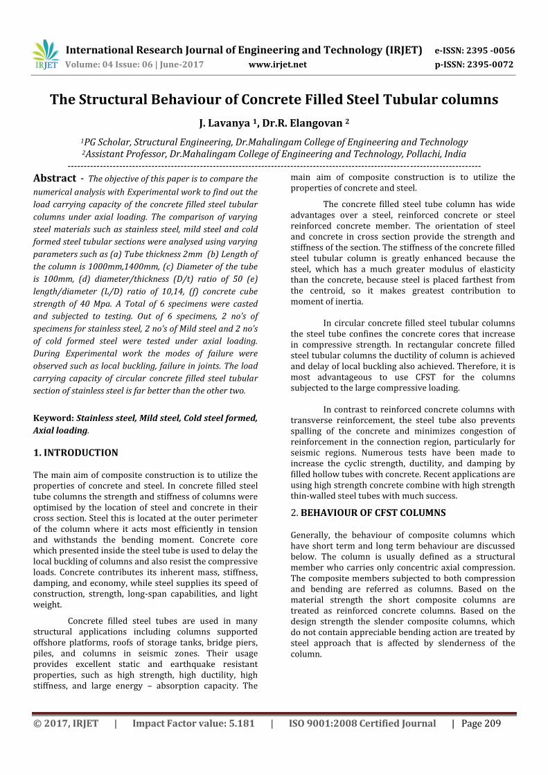
Fig 5. Total deformation of Mild steel (long column)
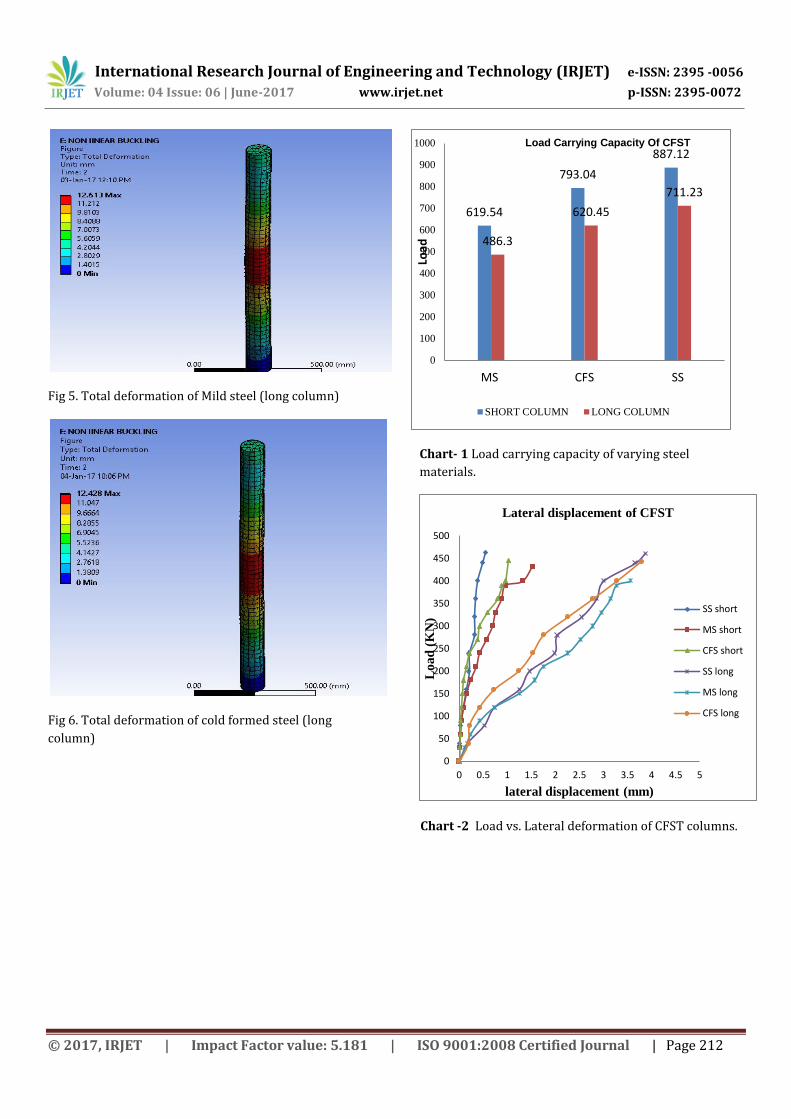
Fig 6. Total deformation of cold formed steel (long
column)
Chart- 1 Load carrying capacity of varying steel
materials.
Chart -2 Load vs. Lateral deformation of CFST columns.
619.54
793.04
887.12
486.3
620.45
711.23
0
100
200
300
400
500
600
700
800
900
1000
MS CFS SS
Load
SHORT COLUMN LONG COLUMN
Load Carrying Capacity Of CFST
0
50
100
150
200
250
300
350
400
450
500
0 0.5 1 1.5 2 2.5 3 3.5 4 4.5 5
Lo
ad
(K
N)
lateral displacement (mm)
Lateral displacement of CFST
SS short
MS short
CFS short
SS long
MS long
CFS long

International Research Journal of Engineering and Technology (IRJET) e-ISSN: 2395 -0056
Volume: 04 Issue: 06 | June-2017 www.irjet.net p-ISSN: 2395-0072
© 2017, IRJET | Impact Factor value: 5.181 | ISO 9001:2008 Certified Journal | Page 213
Chart-3 Load vs. Axial deformation of short column and
long column.
4. EXPERIMENTAL WORK
A total of 6 specimens were casted and subjected to
testing. The column specimens were classified into two
different types. Each type of columns consisted of three
specimens filled with plain concrete.
Table 1: Details of specimen.
S.no
Type of steel
No. of specimen
Length (L) mm
Diameter (D) mm
Thickness (t) mm
1 Stainless steel
1 1000 100 2
2 Stainless steel
1 1400 100 2
3 Mild steel
1 1000 100 2
4 Mild steel
1 1400 100 2
5 Cold formed steel(CFS)
1 1000 100 2
6 CFS 1 1400 100 2
4.1 Test setup
The six specimens were taken for the testing after completion of curing period of 28 days. The testing was carried out in loading frame using load cell. The columns
were hinged at both ends and axial compressive load was applied.
Fig-10. Test setup for Lateral deformation
4.2 Experiment results
The graph for axial deformation and lateral deformation
were plotted as per the values got in experimental work.
The graphs are shown below
0
100
200
300
400
500
600
700
800
900
1000
0 2 4 6 8 10 12 14
Lo
ad
Axial deformation
SS short MS short CFS short
SS long MS long CFSlong
International Research Journal of Engineering and Technology (IRJET) e-ISSN: 2395 -0056
Volume: 04 Issue: 06 | June-2017 www.irjet.net p-ISSN: 2395-0072
© 2017, IRJET | Impact Factor value: 5.181 | ISO 9001:2008 Certified Journal | Page 214
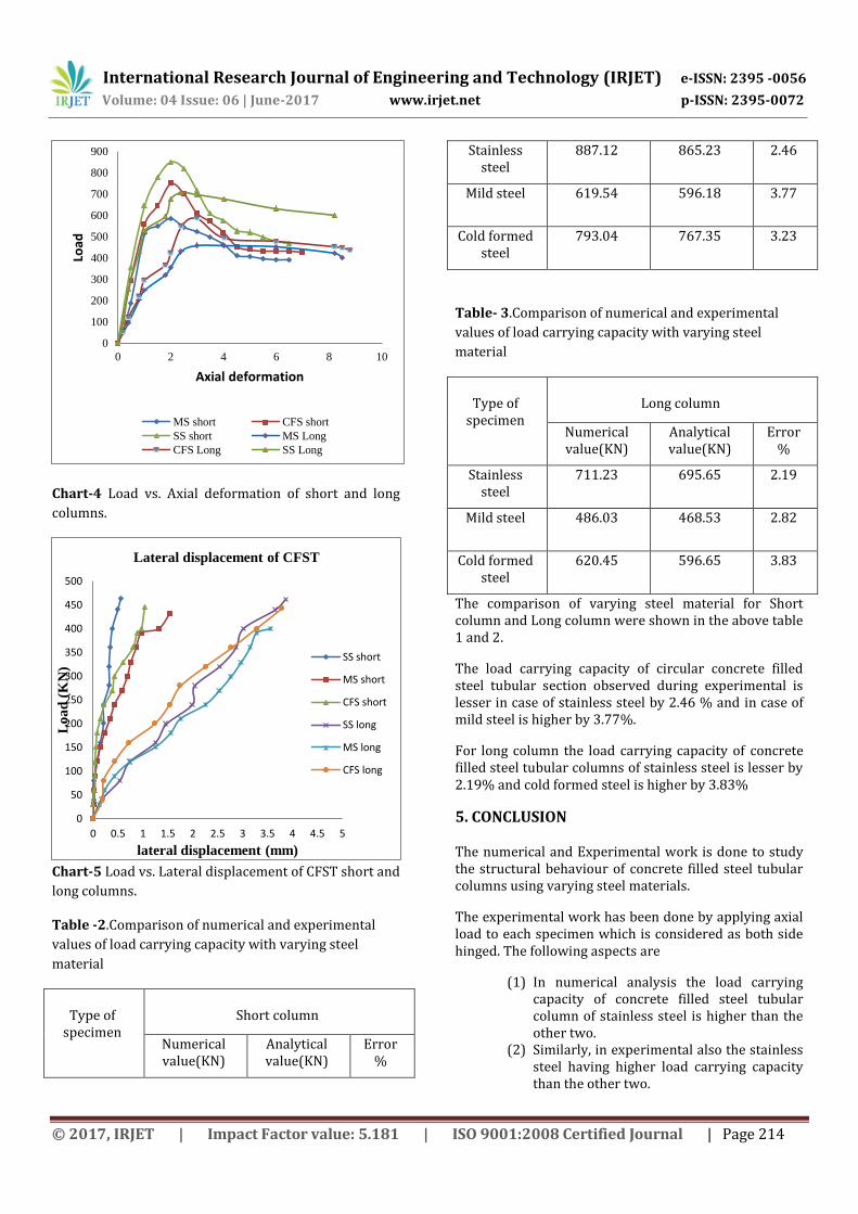
Chart-4 Load vs. Axial deformation of short and long
columns.
Chart-5 Load vs. Lateral displacement of CFST short and
long columns.
Table -2.Comparison of numerical and experimental
values of load carrying capacity with varying steel
material
Type of
specimen
Short column
Numerical value(KN)
Analytical value(KN)
Error %
Stainless steel
887.12 865.23 2.46
Mild steel 619.54 596.18 3.77
Cold formed steel
793.04 767.35 3.23
Table- 3.Comparison of numerical and experimental
values of load carrying capacity with varying steel
material
Type of
specimen
Long column
Numerical value(KN)
Analytical value(KN)
Error %
Stainless steel
711.23 695.65 2.19
Mild steel 486.03 468.53 2.82
Cold formed steel
620.45 596.65 3.83
The comparison of varying steel material for Short column and Long column were shown in the above table 1 and 2.
The load carrying capacity of circular concrete filled steel tubular section observed during experimental is lesser in case of stainless steel by 2.46 % and in case of mild steel is higher by 3.77%.
For long column the load carrying capacity of concrete filled steel tubular columns of stainless steel is lesser by 2.19% and cold formed steel is higher by 3.83%
5. CONCLUSION
The numerical and Experimental work is done to study the structural behaviour of concrete filled steel tubular columns using varying steel materials.
The experimental work has been done by applying axial load to each specimen which is considered as both side hinged. The following aspects are
(1) In numerical analysis the load carrying capacity of concrete filled steel tubular column of stainless steel is higher than the other two.
(2) Similarly, in experimental also the stainless steel having higher load carrying capacity than the other two.
0
100
200
300
400
500
600
700
800
900
0 2 4 6 8 10
Load
Axial deformation
MS short CFS short
SS short MS Long
CFS Long SS Long
0
50
100
150
200
250
300
350
400
450
500
0 0.5 1 1.5 2 2.5 3 3.5 4 4.5 5
Lo
ad
(K
N)
lateral displacement (mm)
Lateral displacement of CFST
SS short
MS short
CFS short
SS long
MS long
CFS long
International Research Journal of Engineering and Technology (IRJET) e-ISSN: 2395 -0056
Volume: 04 Issue: 06 | June-2017 www.irjet.net p-ISSN: 2395-0072
© 2017, IRJET | Impact Factor value: 5.181 | ISO 9001:2008 Certified Journal | Page 215
(3) As comparing the short and long column, the short column of varying steel materials attain higher value than long columns.
(4) During, experiment modes of failure were obtained such as local buckling and failure in joints.
(5) Though the rate of stainless steel is higher than the mild steel and cold formed steel. The strength of stainless steel is much better than the other two. So it is preferable to use stainless steel in high performance building.
References
1) P. Bukovskáa* and M. Karmazínováa ” Behaviour of the tubular columns filled by concrete subjected to buckling compression” a Brno University of Technology, Faculty of Civil Engineering, Czech Republic Steel Structures and Bridges 2012.
2) Mohamed Mahmoud El-Heweity “On the
performance of circular concrete-filled high strength steel columns under axial loading “Structural Engineering Department, Faculty of Engineering, Alexandria University, Egypt. Received 16 May 2012; revised 26 May 2012; accepted 27 May 2012.
3) A.L. Krishna, E.P. Chernyshovaa,*, R.R. Sabirova
“Calculating the Strength of Concrete Filled Steel Tube Columns of Solid and Ring Cross-Section” International Conference on Industrial Engineering, ICIE 2016
4) A.L. Krishan, E.A. Troshkina, E.P. Chernyshova “Efficient Design of Concrete Filled Steel Tube Columns” International Conference on Industrial Engineering, ICIE 2016.
5) Kai Xiang*, Guo-hui Wang “ Experimental Study
on Temperature Distribution of Concrete Filled Steel Tube Reinforced Concrete Square Short Columns “Tianjin Fire Research Institute of the Ministry of Public Security, Tianjin 300381, China.
6) W. Leonardo Cortés-Puentesa,*, Dan Palermob,
Alaa Abdulridhaa, Muslim Majeeda “Compressive strength capacity of light gauge steel composite Columns” Department of Civil Engineering, University of Ottawa, 161 Louis Pasteur St., Ottawa ON K1N 6N5, Canada b Department of Civil Engineering, York University, 4700 Keele St., Toronto ON M3J 1P3, Canada.
7) Takeo hirashima and hideki uesugi “Load-
bearing Capacity of H-shaped Steel Columns under
Local Buckling at Elevated Temperature “ Department of Architectural Engineering, Faculty of Engineering Chiba University 1-33, Yayoi-cho, Inage-ku Chiba-city 263-8522, Japan.
8) S. H. Leea†, S. H. Kima, J. S. Bangb, Y. A. Wonc and
S. M. Choia ” Structural Characteristics of Welded Built-up Square Concrete Filled Tubular Stub Columns Associated with Concrete Strength “ (a)Department of Architectural Engineering, University of Seoul, Korea (b) DAELIM. Construction, Inc., Seoul, Korea (c)Ministry of National Defense, Seoul, Korea.
9) Maha M. Hassan *, Hazem M. Ramadan, Mohammed N. Abdel- Mooty,Sherif A. Mourad “Behaviour of concentrically loaded CFT braces connections” Department of Civil Engineering, Cairo University, Gamaa Street, Giza, Egypt.