the structure of crystalline solids · chapter 3 the structure of crystalline solids problem...
TRANSCRIPT

Full file at https://fratstock.eu
Excerpts from this work may be reproduced by instructors for distribution on a not-for-profit basis for testing or instructional purposes only to students enrolled in courses for which the textbook has been adopted. Any other reproduction or translation of this work beyond that permitted by Sections 107 or 108 of the 1976 United States Copyright Act without the permission of the copyright owner is unlawful.
CHAPTER 3
THE STRUCTURE OF CRYSTALLINE SOLIDS
PROBLEM SOLUTIONS
Fundamental Concepts
3.1 What is the difference between atomic structure and crystal structure?
Solution
Atomic structure relates to the number of protons and neutrons in the nucleus of an atom, as well as the
number and probability distributions of the constituent electrons. On the other hand, crystal structure pertains to the
arrangement of atoms in the crystalline solid material.

Full file at https://fratstock.eu
Excerpts from this work may be reproduced by instructors for distribution on a not-for-profit basis for testing or instructional purposes only to students enrolled in courses for which the textbook has been adopted. Any other reproduction or translation of this work beyond that permitted by Sections 107 or 108 of the 1976 United States Copyright Act without the permission of the copyright owner is unlawful.
Unit Cells
Metallic Crystal Structures
3.2 If the atomic radius of aluminum is 0.143 nm, calculate the volume of its unit cell in cubic meters.
Solution
For this problem, we are asked to calculate the volume of a unit cell of aluminum. Aluminum has an FCC
crystal structure (Table 3.1). The FCC unit cell volume may be computed from Equation 3.4 as
VC = 16R3 2 = (16)(0.143 10-9 m)3( 2) = 6.62 10-29 m3

Full file at https://fratstock.eu
Excerpts from this work may be reproduced by instructors for distribution on a not-for-profit basis for testing or instructional purposes only to students enrolled in courses for which the textbook has been adopted. Any other reproduction or translation of this work beyond that permitted by Sections 107 or 108 of the 1976 United States Copyright Act without the permission of the copyright owner is unlawful.
3.3 Show for the body-centered cubic crystal structure that the unit cell edge length a and the atomic
radius R are related through a =4R/ 3 .
Solution
Consider the BCC unit cell shown below
Using the triangle NOP
(NP)2 = a2 + a2 = 2a2
And then for triangle NPQ,
(NQ)2 = (QP)2 + (NP)2
But
NQ = 4R, R being the atomic radius. Also,
QP = a. Therefore,
(4R)2 = a2 + 2a2
or
a = 4R
3

Full file at https://fratstock.eu
Excerpts from this work may be reproduced by instructors for distribution on a not-for-profit basis for testing or instructional purposes only to students enrolled in courses for which the textbook has been adopted. Any other reproduction or translation of this work beyond that permitted by Sections 107 or 108 of the 1976 United States Copyright Act without the permission of the copyright owner is unlawful.
3.4 For the HCP crystal structure, show that the ideal c/a ratio is 1.633.
Solution
A sketch of one-third of an HCP unit cell is shown below.
Consider the tetrahedron labeled as JKLM, which is reconstructed as
The atom at point M is midway between the top and bottom faces of the unit cell--that is
MH = c/2. And, since
atoms at points J, K, and M, all touch one another,
JM = JK = 2R = a
where R is the atomic radius. Furthermore, from triangle JHM,
(JM )2 = (JH )2 (MH)2
or
Full file at https://fratstock.eu
Excerpts from this work may be reproduced by instructors for distribution on a not-for-profit basis for testing or instructional purposes only to students enrolled in courses for which the textbook has been adopted. Any other reproduction or translation of this work beyond that permitted by Sections 107 or 108 of the 1976 United States Copyright Act without the permission of the copyright owner is unlawful.
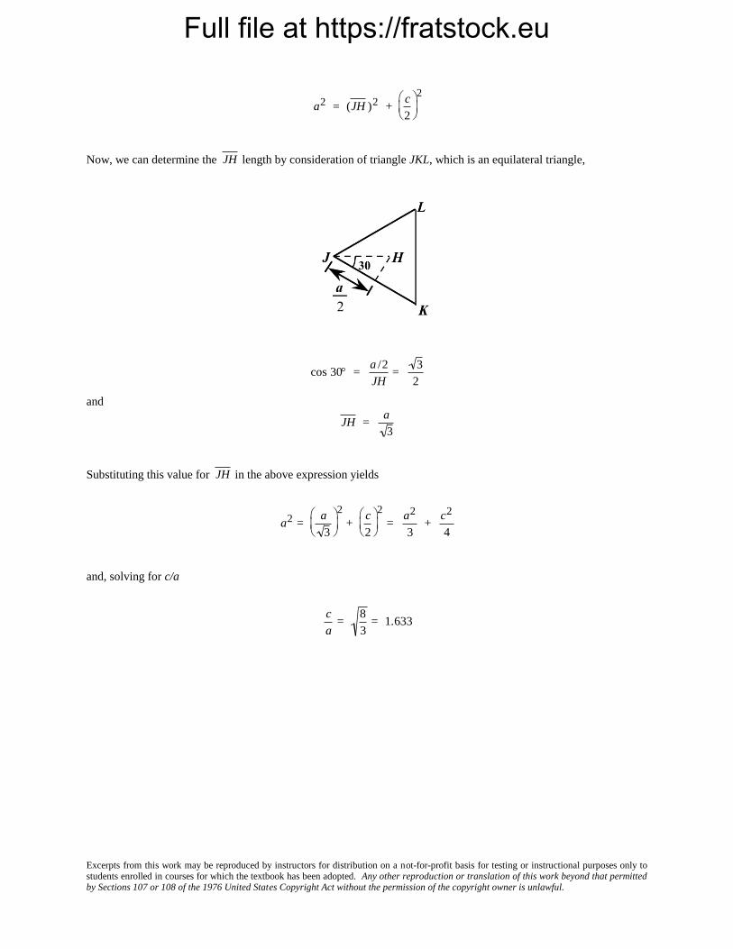
a2 = (JH )2 + c
2
2
Now, we can determine the
JH length by consideration of triangle JKL, which is an equilateral triangle,
cos 30 = a /2
JH=
3
2
and
JH = a
3
Substituting this value for
JH in the above expression yields
a2 = a
3
2
+c
2
2
= a2
3+
c2
4
and, solving for c/a
c
a=
8
3= 1.633

Full file at https://fratstock.eu
Excerpts from this work may be reproduced by instructors for distribution on a not-for-profit basis for testing or instructional purposes only to students enrolled in courses for which the textbook has been adopted. Any other reproduction or translation of this work beyond that permitted by Sections 107 or 108 of the 1976 United States Copyright Act without the permission of the copyright owner is unlawful.
3.5 Show that the atomic packing factor for BCC is 0.68.
Solution
The atomic packing factor is defined as the ratio of sphere volume to the total unit cell volume, or
APF = VS
VC
Since there are two spheres associated with each unit cell for BCC
VS = 2(sphere volume) = 24R3
3
=
8R3
3
Also, the unit cell has cubic symmetry, that is VC = a3. But a depends on R according to Equation 3.3, and
VC =4R
3
3
=64 R3
3 3
Thus,
APF = VS
VC
= 8 R3 /3
64 R3 /3 3= 0.68
Full file at https://fratstock.eu
Excerpts from this work may be reproduced by instructors for distribution on a not-for-profit basis for testing or instructional purposes only to students enrolled in courses for which the textbook has been adopted. Any other reproduction or translation of this work beyond that permitted by Sections 107 or 108 of the 1976 United States Copyright Act without the permission of the copyright owner is unlawful.
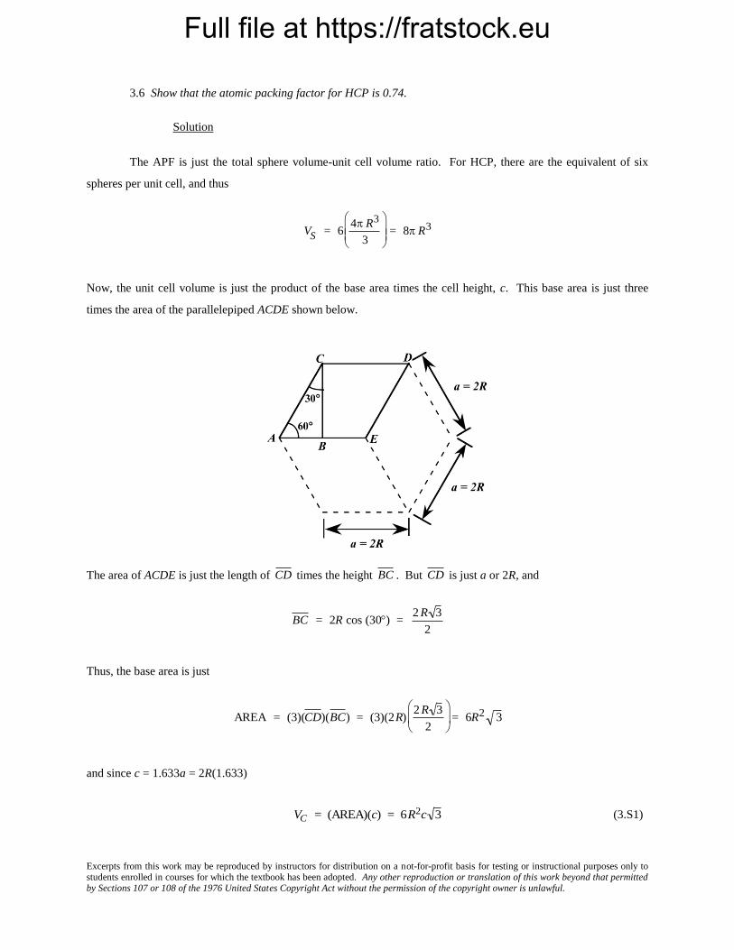
3.6 Show that the atomic packing factor for HCP is 0.74.
Solution
The APF is just the total sphere volume-unit cell volume ratio. For HCP, there are the equivalent of six
spheres per unit cell, and thus
VS = 64 R3
3
= 8 R3
Now, the unit cell volume is just the product of the base area times the cell height, c. This base area is just three
times the area of the parallelepiped ACDE shown below.
The area of ACDE is just the length of
CD times the height
BC . But
CD is just a or 2R, and
BC = 2R cos (30) = 2 R 3
2
Thus, the base area is just
AREA = (3)(CD)(BC) = (3)(2R)2 R 3
2
= 6R2 3
and since c = 1.633a = 2R(1.633)
VC = (AREA)(c) = 6R2c 3 (3.S1)

Full file at https://fratstock.eu
Excerpts from this work may be reproduced by instructors for distribution on a not-for-profit basis for testing or instructional purposes only to students enrolled in courses for which the textbook has been adopted. Any other reproduction or translation of this work beyond that permitted by Sections 107 or 108 of the 1976 United States Copyright Act without the permission of the copyright owner is unlawful.
= (6R2 3)(2)(1.633)R = 12 3 (1.633) R3
Thus,
APF = VS
VC
= 8 R3
12 3 (1.633) R3= 0.74

Full file at https://fratstock.eu
Excerpts from this work may be reproduced by instructors for distribution on a not-for-profit basis for testing or instructional purposes only to students enrolled in courses for which the textbook has been adopted. Any other reproduction or translation of this work beyond that permitted by Sections 107 or 108 of the 1976 United States Copyright Act without the permission of the copyright owner is unlawful.
Density Computations
3.7 Iron has a BCC crystal structure, an atomic radius of 0.124 nm, and an atomic weight of 55.85 g/mol.
Compute and compare its theoretical density with the experimental value found inside the front cover.
Solution
This problem calls for a computation of the density of iron. According to Equation 3.5
=nAFe
VCNA
For BCC, n = 2 atoms/unit cell, and
VC = 4 R
3
3
Thus,
=nAFe
4 R
3
3
NA
= (2 atoms/unit cell)(55.85 g/mol)
(4)(0.124 10-7 cm) / 3 3
/(unit cell)(6.022 1023 atoms/mol)
= 7.90 g/cm3
The value given inside the front cover is 7.87 g/cm3.

Full file at https://fratstock.eu
Excerpts from this work may be reproduced by instructors for distribution on a not-for-profit basis for testing or instructional purposes only to students enrolled in courses for which the textbook has been adopted. Any other reproduction or translation of this work beyond that permitted by Sections 107 or 108 of the 1976 United States Copyright Act without the permission of the copyright owner is unlawful.
3.8 Calculate the radius of an iridium atom, given that Ir has an FCC crystal structure, a density of 22.4
g/cm3, and an atomic weight of 192.2 g/mol.
Solution
We are asked to determine the radius of an iridium atom, given that Ir has an FCC crystal structure. For
FCC, n = 4 atoms/unit cell, and VC =
16R3 2 (Equation 3.4). Now,
= nAIr
VC N A
= nAIr
(16R3 2)N A
And solving for R from the above expression yields
R = nAIr
16N A 2
1/3
= (4 atoms/unit cell) 192.2 g/mol
(16)(22.4 g/cm3)(6.022 1023 atoms/mol)( 2)
1/3
= 1.36 10-8 cm = 0.136 nm

Full file at https://fratstock.eu
Excerpts from this work may be reproduced by instructors for distribution on a not-for-profit basis for testing or instructional purposes only to students enrolled in courses for which the textbook has been adopted. Any other reproduction or translation of this work beyond that permitted by Sections 107 or 108 of the 1976 United States Copyright Act without the permission of the copyright owner is unlawful.
3.9 Calculate the radius of a vanadium atom, given that V has a BCC crystal structure, a density of 5.96
g/cm3, and an atomic weight of 50.9 g/mol.
Solution
This problem asks for us to calculate the radius of a vanadium atom. For BCC, n = 2 atoms/unit cell, and
VC = 4 R
3
3
= 64 R3
3 3
Since, from Equation 3.5
= nAV
VC N A
= nAV
64 R3
3 3
N A
and solving for R the previous equation
R = 3 3nAV
64 N A
1/3
and incorporating values of parameters given in the problem statement
R = (3 3) (2 atoms/unit cell) (50.9 g/mol)
(64)(5.96 g/cm3)(6.022 1023 atoms/mol)
1/3
= 1.32 10-8 cm = 0.132 nm

Full file at https://fratstock.eu
Excerpts from this work may be reproduced by instructors for distribution on a not-for-profit basis for testing or instructional purposes only to students enrolled in courses for which the textbook has been adopted. Any other reproduction or translation of this work beyond that permitted by Sections 107 or 108 of the 1976 United States Copyright Act without the permission of the copyright owner is unlawful.
3.10 Some hypothetical metal has the simple cubic crystal structure shown in Figure 3.24. If its atomic
weight is 70.4 g/mol and the atomic radius is 0.126 nm, compute its density.
Solution
For the simple cubic crystal structure, the value of n in Equation 3.5 is unity since there is only a single
atom associated with each unit cell. Furthermore, for the unit cell edge length, a = 2R (Figure 3.24). Therefore,
employment of Equation 3.5 yields
= nA
VC N A
= nA
(2 R)3 N A
and incorporating values of the other parameters provided in the problem statement leads to
= (1 atom/unit cell)(70.4 g/mol)
(2)(1.26 10-8
cm)
3
/(unit cell)
(6.022 1023 atoms/mol)
7.31 g/cm3

Full file at https://fratstock.eu
Excerpts from this work may be reproduced by instructors for distribution on a not-for-profit basis for testing or instructional purposes only to students enrolled in courses for which the textbook has been adopted. Any other reproduction or translation of this work beyond that permitted by Sections 107 or 108 of the 1976 United States Copyright Act without the permission of the copyright owner is unlawful.
3.11 Zirconium has an HCP crystal structure and a density of 6.51 g/cm3.
(a) What is the volume of its unit cell in cubic meters?
(b) If the c/a ratio is 1.593, compute the values of c and a.
Solution
(a) The volume of the Zr unit cell may be computed using Equation 3.5 as
VC nAZr
N A
Now, for HCP, n = 6 atoms/unit cell, and for Zr, AZr
= 91.22 g/mol. Thus,
VC (6 atoms/unit cell)(91.22 g/mol)
(6.51 g/cm3)(6.022 1023 atoms/mol)
= 1.396 10-22 cm3/unit cell = 1.396 10-28 m3/unit cell
(b) From Equation 3.S1 of the solution to Problem 3.6, for HCP
VC = 6R2c 3
But, since a = 2R, (i.e., R = a/2) then
VC = 6a
2
2
c 3 3 3 a2c
2
but, since c = 1.593a
VC = 3 3 (1.593) a3
2= 1.396 10-22 cm3/unit cell
Now, solving for a
a = (2)(1.396 10-22 cm3)
(3)( 3) (1.593)
1/3

Full file at https://fratstock.eu
Excerpts from this work may be reproduced by instructors for distribution on a not-for-profit basis for testing or instructional purposes only to students enrolled in courses for which the textbook has been adopted. Any other reproduction or translation of this work beyond that permitted by Sections 107 or 108 of the 1976 United States Copyright Act without the permission of the copyright owner is unlawful.
= 3.23 10-8 cm = 0.323 nm
And finally
c = 1.593a = (1.593)(0.323 nm) = 0.515 nm

Full file at https://fratstock.eu
Excerpts from this work may be reproduced by instructors for distribution on a not-for-profit basis for testing or instructional purposes only to students enrolled in courses for which the textbook has been adopted. Any other reproduction or translation of this work beyond that permitted by Sections 107 or 108 of the 1976 United States Copyright Act without the permission of the copyright owner is unlawful.
3.12 Using atomic weight, crystal structure, and atomic radius data tabulated inside the front cover,
compute the theoretical densities of lead, chromium, copper, and cobalt, and then compare these values with the
measured densities listed in this same table. The c/a ratio for cobalt is 1.623.
Solution
Since Pb has an FCC crystal structure, n = 4, and VC
=
16R3 2 (Equation 3.4). Also, R = 0.175 nm (1.75
10-8 cm) and APb
= 207.2 g/mol. Employment of Equation 3.5 yields
= nAPb
VC N A
(4 atoms/unit cell)(207.2 g/mol)
(16)(1.75 10-8 cm)3( 2) /(unit cell) (6.022 1023 atoms/mol)
= 11.35 g/cm3
The value given in the table inside the front cover is 11.35 g/cm3.
Chromium has a BCC crystal structure for which n = 2 and VC
= a3 =
4 R
3
3
(Equation 3.3); also ACr =
52.00g/mol and R = 0.125 nm. Therefore, employment of Equation 3.5 leads to
(2 atoms/unit cell)(52.00 g/mol)
(4)(1.25 10-8 cm)3
3
/(unit cell)
(6.022 1023 atoms/mol)
= 7.18 g/cm3
The value given in the table is 7.19 g/cm3.
Copper also has an FCC crystal structure and therefore
(4 atoms/unit cell)(63.55 g/mol)
(2)(1.28 10-8 cm)( 2) 3/(unit cell )
(6.022 1023 atoms/mol)
= 8.90 g/cm3

Full file at https://fratstock.eu
Excerpts from this work may be reproduced by instructors for distribution on a not-for-profit basis for testing or instructional purposes only to students enrolled in courses for which the textbook has been adopted. Any other reproduction or translation of this work beyond that permitted by Sections 107 or 108 of the 1976 United States Copyright Act without the permission of the copyright owner is unlawful.
The value given in the table is 8.90 g/cm3.
Cobalt has an HCP crystal structure, and from the solution to Problem 3.6 (Equation 3.S1),
VC = 6R2c 3
and, since c = 1.623a and a = 2R, c = (1.623)(2R); hence
VC 6R2(1.623)(2R) 3 (19.48)( 3)R3
(19.48)( 3)(1.25 108 cm)3
6.59 1023 cm3/unit cell
Also, there are 6 atoms/unit cell for HCP. Therefore the theoretical density is
= nACo
VC N A
(6 atoms/unit cell)(58.93 g/mol)
(6.59 10-23 cm3/unit cell)(6.022 1023 atoms/mol)
= 8.91 g/cm3
The value given in the table is 8.9 g/cm3.

Full file at https://fratstock.eu
Excerpts from this work may be reproduced by instructors for distribution on a not-for-profit basis for testing or instructional purposes only to students enrolled in courses for which the textbook has been adopted. Any other reproduction or translation of this work beyond that permitted by Sections 107 or 108 of the 1976 United States Copyright Act without the permission of the copyright owner is unlawful.
3.13 Rhodium has an atomic radius of 0.1345 nm and a density of 12.41 g/cm3. Determine whether it has
an FCC or BCC crystal structure.
Solution
In order to determine whether Rh has an FCC or a BCC crystal structure, we need to compute its density for
each of the crystal structures. For FCC, n = 4, and a =
2R 2 (Equation 3.1). Also, from Figure 2.6, its atomic
weight is 102.91 g/mol. Thus, for FCC (employing Equation 3.5)
nARh
a3N A
nARh
(2R 2)3 N A
= (4 atoms/unit cell)(102.91 g/mol)
(2)(1.345 10-8 cm)( 2) 3
/(unit cell)
(6.022 1023 atoms /mol)
= 12.41 g/cm3
which is the value provided in the problem statement. Therefore, Rh has the FCC crystal structure.

Full file at https://fratstock.eu
Excerpts from this work may be reproduced by instructors for distribution on a not-for-profit basis for testing or instructional purposes only to students enrolled in courses for which the textbook has been adopted. Any other reproduction or translation of this work beyond that permitted by Sections 107 or 108 of the 1976 United States Copyright Act without the permission of the copyright owner is unlawful.
3.14 Below are listed the atomic weight, density, and atomic radius for three hypothetical alloys. For
each determine whether its crystal structure is FCC, BCC, or simple cubic and then justify your determination. A
simple cubic unit cell is shown in Figure 3.24.
Alloy Atomic Weight Density Atomic Radius
(g/mol) (g/cm3) (nm)
A 77.4 8.22 0.125
B 107.6 13.42 0.133
C 127.3 9.23 0.142
Solution
For each of these three alloys we need, by trial and error, to calculate the density using Equation 3.5, and
compare it to the value cited in the problem. For SC, BCC, and FCC crystal structures, the respective values of n are
1, 2, and 4, whereas the expressions for a (since VC = a3) are 2R,
2R 2 , and
4R
3.
For alloy A, let us calculate assuming a simple cubic crystal structure.
= nAA
VC N A
= nAA
2R 3
N A
= (1 atom/unit cell)(77.4 g/mol)
(2)(1.25 108) 3/(unit cell)
(6.022 1023 atoms/mol)
= 8.22 g/cm3
Therefore, its crystal structure is simple cubic.
For alloy B, let us calculate assuming an FCC crystal structure.
= nAB
(2 R 2)3 N A

Full file at https://fratstock.eu
Excerpts from this work may be reproduced by instructors for distribution on a not-for-profit basis for testing or instructional purposes only to students enrolled in courses for which the textbook has been adopted. Any other reproduction or translation of this work beyond that permitted by Sections 107 or 108 of the 1976 United States Copyright Act without the permission of the copyright owner is unlawful.
= (4 atoms/unit cell)(107.6 g/mol)
2 2 (1.33 10-8 cm) 3/(unit cell)
(6.022 1023 atoms/mol)
= 13.42 g/cm3
Therefore, its crystal structure is FCC.
For alloy C, let us calculate assuming a simple cubic crystal structure.
= nAC
2R 3
N A
= (1 atom/unit cell)(127.3 g/mol)
(2)(1.42 10-8 cm) 3/(unit cell)
(6.022 1023 atoms/mol)
= 9.23 g/cm3
Therefore, its crystal structure is simple cubic.
Full file at https://fratstock.eu
Excerpts from this work may be reproduced by instructors for distribution on a not-for-profit basis for testing or instructional purposes only to students enrolled in courses for which the textbook has been adopted. Any other reproduction or translation of this work beyond that permitted by Sections 107 or 108 of the 1976 United States Copyright Act without the permission of the copyright owner is unlawful.
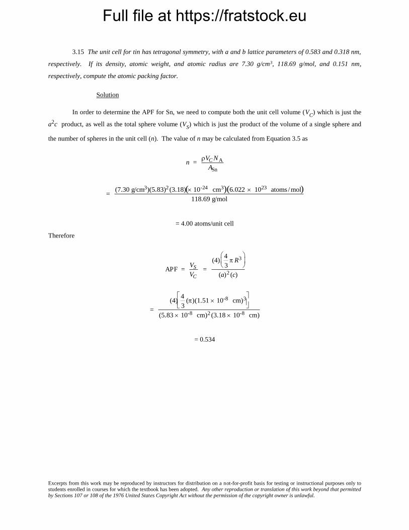
3.15 The unit cell for tin has tetragonal symmetry, with a and b lattice parameters of 0.583 and 0.318 nm,
respectively. If its density, atomic weight, and atomic radius are 7.30 g/cm3, 118.69 g/mol, and 0.151 nm,
respectively, compute the atomic packing factor.
Solution
In order to determine the APF for Sn, we need to compute both the unit cell volume (VC
) which is just the
a2c product, as well as the total sphere volume (VS) which is just the product of the volume of a single sphere and
the number of spheres in the unit cell (n). The value of n may be calculated from Equation 3.5 as
n = VC N A
ASn
= (7.30 g/cm3)(5.83)2 (3.18)( 10-24 cm3)(6.022 1023 atoms /mol)
118.69 g/mol
= 4.00 atoms/unit cell
Therefore
APF = VS
VC
=
(4)4
3 R3
(a)2 (c)
=
(4)4
3()(1.51 10-8 cm)3
(5.83 10-8 cm)2 (3.18 10-8 cm)
= 0.534

Full file at https://fratstock.eu
Excerpts from this work may be reproduced by instructors for distribution on a not-for-profit basis for testing or instructional purposes only to students enrolled in courses for which the textbook has been adopted. Any other reproduction or translation of this work beyond that permitted by Sections 107 or 108 of the 1976 United States Copyright Act without the permission of the copyright owner is unlawful.
3.16 Iodine has an orthorhombic unit cell for which the a, b, and c lattice parameters are 0.479, 0.725,
and 0.978 nm, respectively.
(a) If the atomic packing factor and atomic radius are 0.547 and 0.177 nm, respectively, determine the
number of atoms in each unit cell.
(b) The atomic weight of iodine is 126.91 g/mol; compute its theoretical density.
Solution
(a) For indium, and from the definition of the APF
APF = VS
VC
=
n4
3 R3
abc
we may solve for the number of atoms per unit cell, n, as
n = (APF) abc
4
3 R3
Incorporating values of the above parameters provided in the problem state leads to
= (0.547)(4.79 10-8 cm)(7.25 10-8 cm)(9.78 10-8 cm)
4
3 (1.77 10-8 cm)3
= 8.0 atoms/unit cell
(b) In order to compute the density, we just employ Equation 3.5 as
= nAI
abc N A
= (8 atoms/unit cell)(126.91 g/mol)
(4.79 10-8 cm)(7.25 10-8 cm)(9.78 10-8 cm) / unit cell (6.022 1023 atoms/mol)
= 4.96 g/cm3
Full file at https://fratstock.eu
Excerpts from this work may be reproduced by instructors for distribution on a not-for-profit basis for testing or instructional purposes only to students enrolled in courses for which the textbook has been adopted. Any other reproduction or translation of this work beyond that permitted by Sections 107 or 108 of the 1976 United States Copyright Act without the permission of the copyright owner is unlawful.
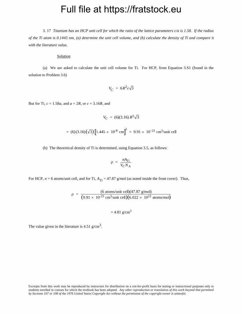
3. 17 Titanium has an HCP unit cell for which the ratio of the lattice parameters c/a is 1.58. If the radius
of the Ti atom is 0.1445 nm, (a) determine the unit cell volume, and (b) calculate the density of Ti and compare it
with the literature value.
Solution
(a) We are asked to calculate the unit cell volume for Ti. For HCP, from Equation 3.S1 (found in the
solution to Problem 3.6)
VC = 6R2c 3
But for Ti, c = 1.58a, and a = 2R, or c = 3.16R, and
VC = (6)(3.16) R3 3
= (6) (3.16)( 3) 1.445 10-8 cm 3 = 9.91 1023 cm3/unit cell
(b) The theoretical density of Ti is determined, using Equation 3.5, as follows:
= nATi
VC N A
For HCP, n = 6 atoms/unit cell, and for Ti, ATi = 47.87 g/mol (as noted inside the front cover). Thus,
= (6 atoms/unit cell)(47.87 g/mol)
(9.91 10-23 cm3/unit cell)(6.022 1023 atoms/mol)
= 4.81 g/cm3
The value given in the literature is 4.51 g/cm3.

Full file at https://fratstock.eu
Excerpts from this work may be reproduced by instructors for distribution on a not-for-profit basis for testing or instructional purposes only to students enrolled in courses for which the textbook has been adopted. Any other reproduction or translation of this work beyond that permitted by Sections 107 or 108 of the 1976 United States Copyright Act without the permission of the copyright owner is unlawful.
3.18 Zinc has an HCP crystal structure, a c/a ratio of 1.856, and a density of 7.13 g/cm3. Compute the
atomic radius for Zn.
Solution
In order to calculate the atomic radius for Zn, we must use Equation 3.5, as well as the expression which
relates the atomic radius to the unit cell volume for HCP; Equation 3.S1 (from Problem 3.6) is as follows:
VC = 6R2c 3
In this case c = 1.856a, but, for HCP, a = 2R, which means that
VC = 6R2(1.856)(2R) 3 (1.856)(12 3)R3
And from Equation 3.5, the density is equal to
= nAZn
VC N A
= nAZn
(1.856)(12 3)R3N A
And, solving for R from the above equation leads to the following:
R = nAZn
(1.856)(12 3) N A
1/3
And incorporating appropriate values for the parameters in this equation leads to
R = (6 atoms/unit cell) (65.41 g/mol)
(1.856)(12 3)(7.13 g/cm3)(6.022 1023 atoms/mol)
1/3
= 1.33 10-8 cm = 0.133 nm
Full file at https://fratstock.eu
Excerpts from this work may be reproduced by instructors for distribution on a not-for-profit basis for testing or instructional purposes only to students enrolled in courses for which the textbook has been adopted. Any other reproduction or translation of this work beyond that permitted by Sections 107 or 108 of the 1976 United States Copyright Act without the permission of the copyright owner is unlawful.
3.19 Rhenium has an HCP crystal structure, an atomic radius of 0.137 nm, and a c/a ratio of 1.615.
Compute the volume of the unit cell for Re.
Solution
In order to compute the volume of the unit cell for Re, it is necessary to use Equation 3.S1 (found in Problem 3.6),
that is
VC = 6R2c 3
The problem states that c = 1.615a, and a = 2R. Therefore
VC = (1.615)(12 3) R3
= (1.615)(12 3)(1.37 10-8 cm)3 = 8.63 10-23 cm3 = 8.63 10-2 nm3

Full file at https://fratstock.eu
Excerpts from this work may be reproduced by instructors for distribution on a not-for-profit basis for testing or instructional purposes only to students enrolled in courses for which the textbook has been adopted. Any other reproduction or translation of this work beyond that permitted by Sections 107 or 108 of the 1976 United States Copyright Act without the permission of the copyright owner is unlawful.
Crystal Systems 3.20 Below is a unit cell for a hypothetical metal.
(a) To which crystal system does this unit cell belong?
(b) What would this crystal structure be called?
(c) Calculate the density of the material, given that its atomic weight is 141 g/mol.
Solution
(a) The unit cell shown in the problem statement belongs to the tetragonal crystal system since a = b = 0.30
nm, c = 0.40 nm, and = = = 90.
(b) The crystal structure would be called body-centered tetragonal.
(c) As with BCC, n = 2 atoms/unit cell. Also, for this unit cell
VC = (3.0 108 cm)2(4.0 108 cm)
= 3.60 1023 cm3/unit cell
Thus, using Equation 3.5, the density is equal to
= nA
VC NA
= (2 atoms/unit cell) (141 g/mol)
(3.60 10-23 cm3/unit cell)(6.022 1023 atoms/mol)
= 13.0 g/cm3
Full file at https://fratstock.eu
Excerpts from this work may be reproduced by instructors for distribution on a not-for-profit basis for testing or instructional purposes only to students enrolled in courses for which the textbook has been adopted. Any other reproduction or translation of this work beyond that permitted by Sections 107 or 108 of the 1976 United States Copyright Act without the permission of the copyright owner is unlawful.
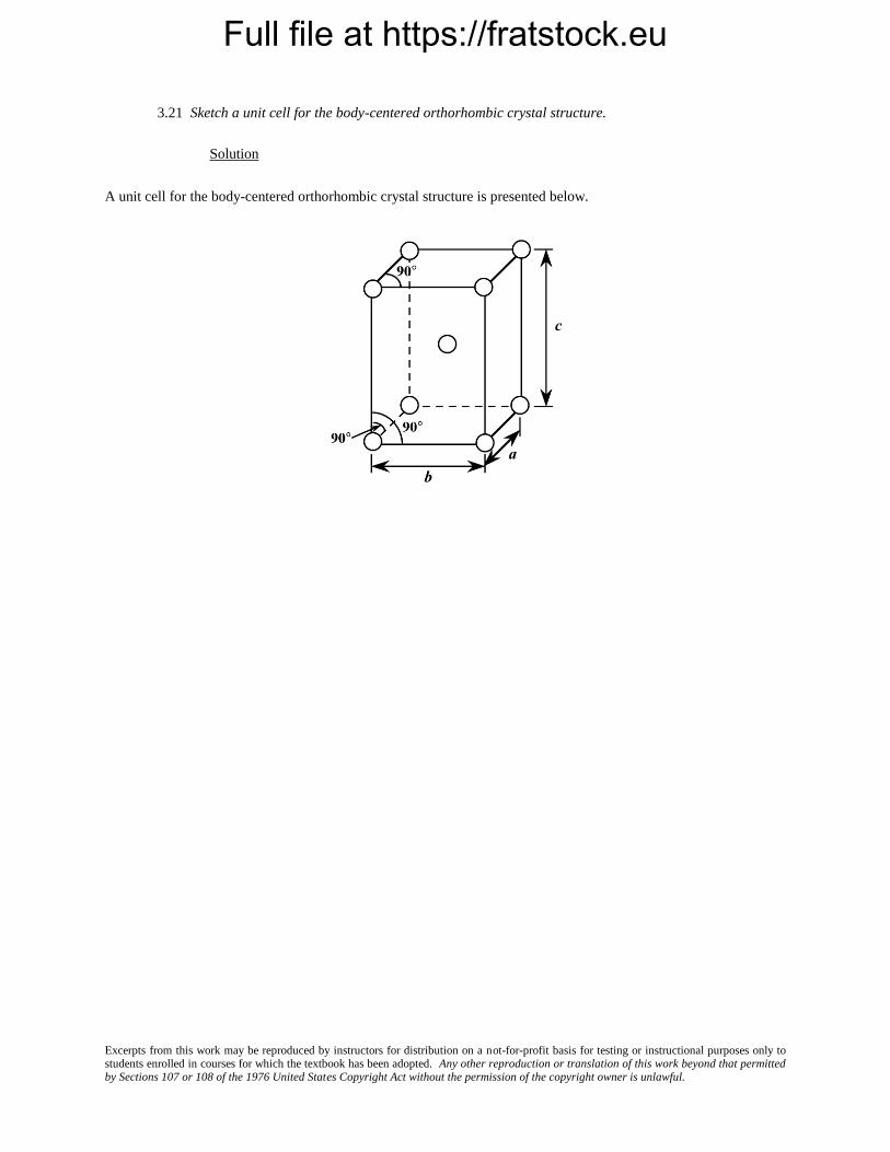
3.21 Sketch a unit cell for the body-centered orthorhombic crystal structure.
Solution
A unit cell for the body-centered orthorhombic crystal structure is presented below.
Full file at https://fratstock.eu
Excerpts from this work may be reproduced by instructors for distribution on a not-for-profit basis for testing or instructional purposes only to students enrolled in courses for which the textbook has been adopted. Any other reproduction or translation of this work beyond that permitted by Sections 107 or 108 of the 1976 United States Copyright Act without the permission of the copyright owner is unlawful.
Point Coordinates
3.22 List the point coordinates for all atoms that are associated with the FCC unit cell (Figure 3.1).
Solution
From Figure 3.1b, the atom located of the origin of the unit cell has the coordinates 000. Coordinates for
other atoms in the bottom face are 100, 110, 010, and
1
2
1
20. (The z coordinate for all these points is zero.)
For the top unit cell face, the coordinates are 001, 101, 111, 011, and
1
2
1
21.
Coordinates for those atoms that are positioned at the centers of both side faces, and centers of both front
and back faces need to be specified. For the front and back-center face atoms, the coordinates are
11
2
1
2 and
01
2
1
2,
respectively. While for the left and right side center-face atoms, the respective coordinates are
1
20
1
2 and
1
21
1
2.

Full file at https://fratstock.eu
Excerpts from this work may be reproduced by instructors for distribution on a not-for-profit basis for testing or instructional purposes only to students enrolled in courses for which the textbook has been adopted. Any other reproduction or translation of this work beyond that permitted by Sections 107 or 108 of the 1976 United States Copyright Act without the permission of the copyright owner is unlawful.
3.23 List the point coordinates of the titanium, barium, and oxygen ions for a unit cell of the perovskite
crystal structure (Figure 12.6).
Solution
In Figure 12.6, the barium ions are situated at all corner positions. The point coordinates for these ions are
as follows: 000, 100, 110, 010, 001, 101, 111, and 011.
The oxygen ions are located at all face-centered positions; therefore, their coordinates are
1
2
1
20,
1
2
1
21,
11
2
1
2,
01
2
1
2,
1
20
1
2, and
1
21
1
2.
And, finally, the titanium ion resides at the center of the cubic unit cell, with coordinates
1
2
1
2
1
2.

Full file at https://fratstock.eu
Excerpts from this work may be reproduced by instructors for distribution on a not-for-profit basis for testing or instructional purposes only to students enrolled in courses for which the textbook has been adopted. Any other reproduction or translation of this work beyond that permitted by Sections 107 or 108 of the 1976 United States Copyright Act without the permission of the copyright owner is unlawful.
3.24 List the point coordinates of all atoms that are associated with the diamond cubic unit cell (Figure
12.15).
Solution
First of all, one set of carbon atoms occupy all corner positions of the cubic unit cell; the coordinates of
these atoms are as follows: 000, 100, 110, 010, 001, 101, 111, and 011.
Another set of atoms reside on all of the face-centered positions, with the following coordinates:
1
2
1
20,
1
2
1
21,
11
2
1
2,
01
2
1
2,
1
20
1
2, and
1
21
1
2.
The third set of carbon atoms are positioned within the interior of the unit cell. Using an x-y-z coordinate
system oriented as in Figure 3.4, the coordinates of the atom that lies toward the lower-left-front of the unit cell has
the coordinates
3
4
1
4
1
4, whereas the atom situated toward the lower-right-back of the unit cell has coordinates of
1
4
3
4
1
4. Also, the carbon atom that resides toward the upper-left-back of the unit cell has the
1
4
1
4
3
4 coordinates.
And, the coordinates of the final atom, located toward the upper-right-front of the unit cell, are
3
4
3
4
3
4.

Full file at https://fratstock.eu
Excerpts from this work may be reproduced by instructors for distribution on a not-for-profit basis for testing or instructional purposes only to students enrolled in courses for which the textbook has been adopted. Any other reproduction or translation of this work beyond that permitted by Sections 107 or 108 of the 1976 United States Copyright Act without the permission of the copyright owner is unlawful.
3.25 Sketch a tetragonal unit cell , and within that cell indicate locations of the
1
2 1
1
2 and
1
4
1
2
3
4 point
coordinates.
Solution
A tetragonal unit in which are shown the
1
2 1
1
2 and
1
4
1
2
3
4 point coordinates is presented below.

Full file at https://fratstock.eu
Excerpts from this work may be reproduced by instructors for distribution on a not-for-profit basis for testing or instructional purposes only to students enrolled in courses for which the textbook has been adopted. Any other reproduction or translation of this work beyond that permitted by Sections 107 or 108 of the 1976 United States Copyright Act without the permission of the copyright owner is unlawful.
3.26 Using the Molecule Definition Utility found in both “Metallic Crystal Structures and
Crystallography” and “Ceramic Crystal Structures” modules of VMSE, located on the book’s web site
[www.wiley.com/college/Callister (Student Companion Site)], generate a three-dimensional unit cell for the
intermetallic compound AuCu3 given the following: (1) the unit cell is cubic with an edge length of 0.374 nm, (2)
gold atoms are situated at all cube corners, and (3) copper atoms are positioned at the centers of all unit cell faces.
Solution
First of all, open the “Molecular Definition Utility”; it may be found in either of “Metallic Crystal
Structures and Crystallography” or “Ceramic Crystal Structures” modules.
In the “Step 1” window, it is necessary to define the atom types, colors for the spheres (atoms), and specify
atom sizes. Let us enter “Au” as the name for the gold atoms (since “Au” the symbol for gold), and “Cu” as the
name for the copper atoms. Next it is necessary to choose a color for each atom type from the selections that appear
in the pull-down menu—for example, “Yellow” for Au and “Red” for Cu. In the “Atom Size” window, it is
necessary to enter an atom/ion size. In the instructions for this step, it is suggested that the atom/ion diameter in
nanometers be used. From the table found inside the front cover of the textbook, the atomic radii for gold and
copper are 0.144 nm and 0.128 nm, respectively, and, therefore, their ionic diameters are twice these values (i.e.,
0.288 nm and 0.256 nm); therefore, we enter the values “0.288” and “0.256” for the two atom types. Now click on
the “Register” button, followed by clicking on the “Go to Step 2” button.
In the “Step 2” window we specify positions for all of the atoms within the unit cell; their point coordinates
are specified in the problem statement. Let’s begin with gold. Click on the yellow sphere that is located to the right
of the “Molecule Definition Utility” box. Again, Au atoms are situated at all eight corners of the cubic unit cell.
One Au will be positioned at the origin of the coordinate system—i.e., its point coordinates are 000, and, therefore,
we enter a “0” (zero) in each of the “x”, “y”, and “z” atom position boxes. Next we click on the “Register Atom
Position” button. Now we enter the coordinates of another gold atom; let us arbitrarily select the one that resides at
the corner of the unit cell that is one unit-cell length along the x-axis (i.e., at the 100 point coordinate). Inasmuch as
it is located a distance of a units along the x-axis the value of “0.374” is entered in the “x” atom position box (since
this is the value of a given in the problem statement); zeros are entered in each of the “y” and “z” position boxes.
We repeat this procedure for the remaining six Au atoms.
After this step has been completed, it is necessary to specify positions for the copper atoms, which are
located at all six face-centered sites. To begin, we click on the red sphere that is located next to the “Molecule
Definition Utility” box. The point coordinates for some of the Cu atoms are fractional ones; in these instances, the a
unit cell length (i.e., 0.374) is multiplied by the fraction. For example, one Cu atom is located
11
2
1
2 coordinate.
Therefore, the x, y, and z atoms positions are (1)(0.374) = 0.374,
1
2(0.374) = 0.187, and
1
2(0.374) = 0.187,
respectively.
For the gold atoms, the x, y, and z atom position entries for all 8 sets of point coordinates are as follows:

Full file at https://fratstock.eu
Excerpts from this work may be reproduced by instructors for distribution on a not-for-profit basis for testing or instructional purposes only to students enrolled in courses for which the textbook has been adopted. Any other reproduction or translation of this work beyond that permitted by Sections 107 or 108 of the 1976 United States Copyright Act without the permission of the copyright owner is unlawful.
0, 0, and 0
0.374, 0, and 0
0, 0.374, and 0
0, 0, and 0.374
0, 0.374, 0.374
0.374, 0, 0.374
0.374, 0.374, 0
0.374, 0.374, 0.374
Now, for the copper atoms, the x, y, and z atom position entries for all 6 sets of point coordinates are as
follows:
0.187, 0.187, 0
0.187, 0, 0.187
0, 0.187, 0.187
0.374, 0.187, 0.187
0.187, 0.374, 0.187
0.187, 0.187, 0.374
In Step 3, we may specify which atoms are to be represented as being bonded to one another, and which
type of bond(s) to use (single solid, single dashed, double, and triple are possibilities), or we may elect to not
represent any bonds at all (in which case we are finished). If it is decided to show bonds, probably the best thing to
do is to represent unit cell edges as bonds. This image may be rotated by using mouse click-and-drag
Your image should appear as the following screen shot. Here the gold atoms appear lighter than the copper
atoms.

Full file at https://fratstock.eu
Excerpts from this work may be reproduced by instructors for distribution on a not-for-profit basis for testing or instructional purposes only to students enrolled in courses for which the textbook has been adopted. Any other reproduction or translation of this work beyond that permitted by Sections 107 or 108 of the 1976 United States Copyright Act without the permission of the copyright owner is unlawful.
[Note: Unfortunately, with this version of the Molecular Definition Utility, it is not possible to save either the data
or the image that you have generated. You may use screen capture (or screen shot) software to record and store your
image.]
Full file at https://fratstock.eu
Excerpts from this work may be reproduced by instructors for distribution on a not-for-profit basis for testing or instructional purposes only to students enrolled in courses for which the textbook has been adopted. Any other reproduction or translation of this work beyond that permitted by Sections 107 or 108 of the 1976 United States Copyright Act without the permission of the copyright owner is unlawful.
Crystallographic Directions
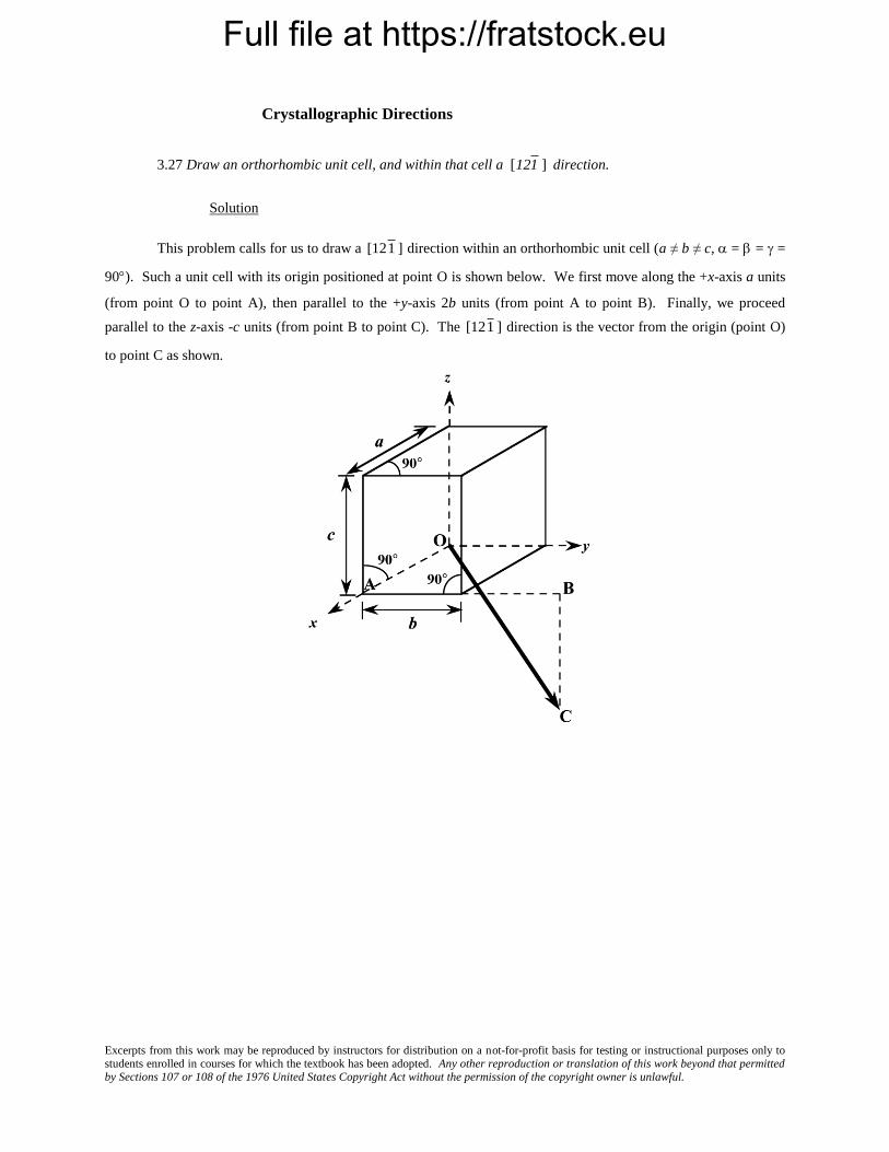
3.27 Draw an orthorhombic unit cell, and within that cell a
[121 ] direction.
Solution
This problem calls for us to draw a
[121 ] direction within an orthorhombic unit cell (a ≠ b ≠ c, = = =
90). Such a unit cell with its origin positioned at point O is shown below. We first move along the +x-axis a units
(from point O to point A), then parallel to the +y-axis 2b units (from point A to point B). Finally, we proceed
parallel to the z-axis -c units (from point B to point C). The
[121 ] direction is the vector from the origin (point O)
to point C as shown.

Full file at https://fratstock.eu
Excerpts from this work may be reproduced by instructors for distribution on a not-for-profit basis for testing or instructional purposes only to students enrolled in courses for which the textbook has been adopted. Any other reproduction or translation of this work beyond that permitted by Sections 107 or 108 of the 1976 United States Copyright Act without the permission of the copyright owner is unlawful.
3.28 Sketch a monoclinic unit cell, and within that cell a
[01 1 ] direction.
Solution
This problem asks that a
[01 1] direction be drawn within a monoclinic unit cell (a ≠ b ≠ c, and = = 90º
≠ ). One such unit cell with its origin at point O is sketched below. For this direction, there is no projection along
the x-axis since the first index is zero; thus, the direction lies in the y-z plane. We next move from the origin along
the minus y-axis b units (from point O to point R). Since the final index is a one, move from point R parallel to the z-
axis, c units (to point P). Thus, the
[01 1] direction corresponds to the vector passing from the origin (point O) to
point P, as indicated in the figure.
Full file at https://fratstock.eu
Excerpts from this work may be reproduced by instructors for distribution on a not-for-profit basis for testing or instructional purposes only to students enrolled in courses for which the textbook has been adopted. Any other reproduction or translation of this work beyond that permitted by Sections 107 or 108 of the 1976 United States Copyright Act without the permission of the copyright owner is unlawful.
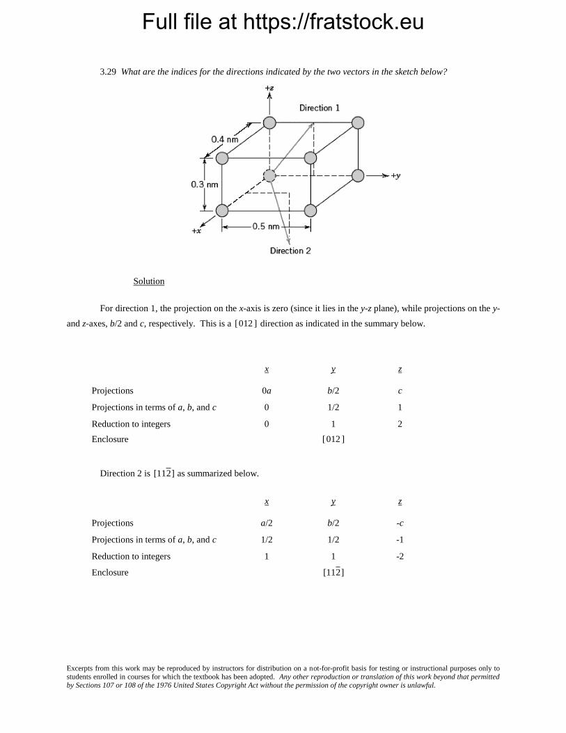
3.29 What are the indices for the directions indicated by the two vectors in the sketch below?
Solution
For direction 1, the projection on the x-axis is zero (since it lies in the y-z plane), while projections on the y-
and z-axes, b/2 and c, respectively. This is a
[012 ] direction as indicated in the summary below.
x y z
Projections 0a b/2 c
Projections in terms of a, b, and c 0 1/2 1
Reduction to integers 0 1 2
Enclosure
[012 ]
Direction 2 is
[112 ] as summarized below.
x y z
Projections a/2 b/2 -c
Projections in terms of a, b, and c 1/2 1/2 -1
Reduction to integers 1 1 -2
Enclosure
[112 ]
Full file at https://fratstock.eu
Excerpts from this work may be reproduced by instructors for distribution on a not-for-profit basis for testing or instructional purposes only to students enrolled in courses for which the textbook has been adopted. Any other reproduction or translation of this work beyond that permitted by Sections 107 or 108 of the 1976 United States Copyright Act without the permission of the copyright owner is unlawful.
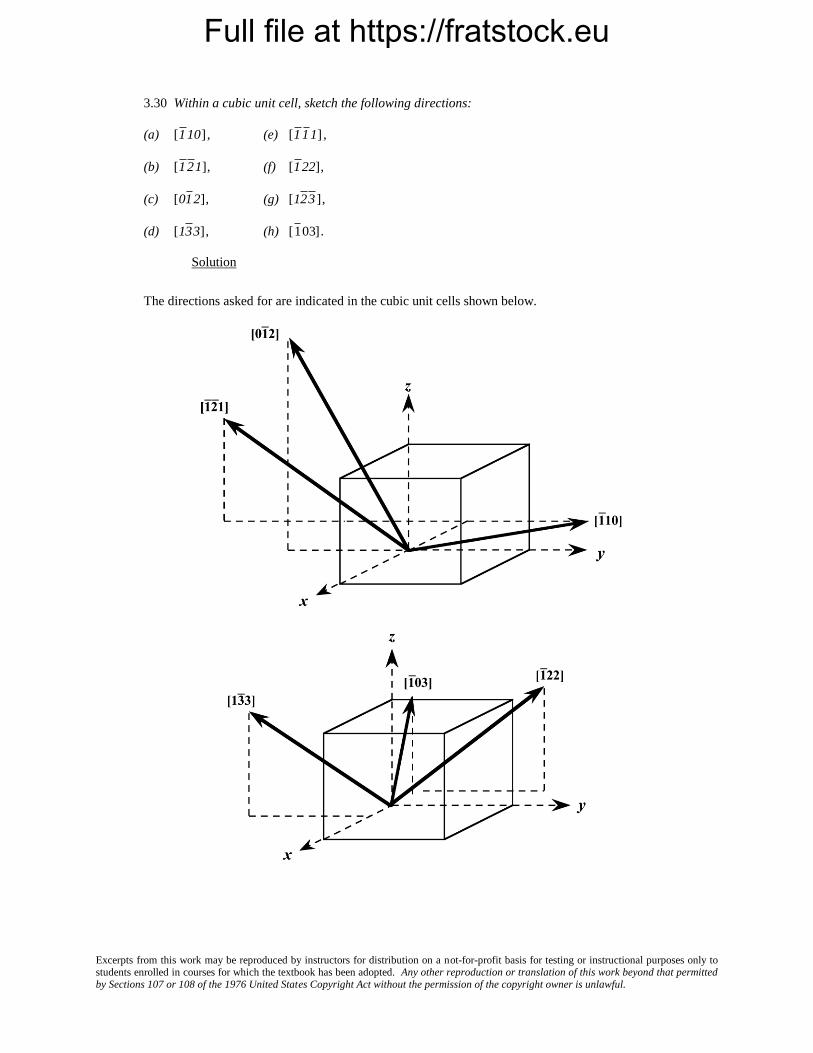
3.30 Within a cubic unit cell, sketch the following directions:
(a)
[1 10] , (e)
[1 1 1] ,
(b)
[1 2 1], (f)
[1 22],
(c)
[01 2], (g)
[12 3 ],
(d)
[13 3], (h)
[1 03].
Solution
The directions asked for are indicated in the cubic unit cells shown below.

Full file at https://fratstock.eu
Excerpts from this work may be reproduced by instructors for distribution on a not-for-profit basis for testing or instructional purposes only to students enrolled in courses for which the textbook has been adopted. Any other reproduction or translation of this work beyond that permitted by Sections 107 or 108 of the 1976 United States Copyright Act without the permission of the copyright owner is unlawful.
3.31 Determine the indices for the directions shown in the following cubic unit cell:
Solution
Direction A is a
[01 1 ]direction, which determination is summarized as follows. We first of all position the
origin of the coordinate system at the tail of the direction vector; then in terms of this new coordinate system
x y z
Projections 0a –b –c
Projections in terms of a, b, and c 0 –1 –1
Reduction to integers not necessary
Enclosure
[01 1 ]
Direction B is a
[2 10] direction, which determination is summarized as follows. We first of all position the
origin of the coordinate system at the tail of the direction vector; then in terms of this new coordinate system x y z
Projections –a
b
2 0c
Projections in terms of a, b, and c –1
1
2 0
Reduction to integers –2 1 0
Enclosure
[2 10]
Direction C is a [112] direction, which determination is summarized as follows. We first of all position the
origin of the coordinate system at the tail of the direction vector; then in terms of this new coordinate system

Full file at https://fratstock.eu
Excerpts from this work may be reproduced by instructors for distribution on a not-for-profit basis for testing or instructional purposes only to students enrolled in courses for which the textbook has been adopted. Any other reproduction or translation of this work beyond that permitted by Sections 107 or 108 of the 1976 United States Copyright Act without the permission of the copyright owner is unlawful.
x y z
Projections
a
2
b
2 c
Projections in terms of a, b, and c
1
2
1
2 1
Reduction to integers 1 1 2
Enclosure [112]
Direction D is a
[112 ] direction, which determination is summarized as follows. We first of all position the
origin of the coordinate system at the tail of the direction vector; then in terms of this new coordinate system x y z
Projections
a
2
b
2 –c
Projections in terms of a, b, and c
1
2
1
2 –1
Reduction to integers 1 1 –2
Enclosure
[112 ]
Full file at https://fratstock.eu
Excerpts from this work may be reproduced by instructors for distribution on a not-for-profit basis for testing or instructional purposes only to students enrolled in courses for which the textbook has been adopted. Any other reproduction or translation of this work beyond that permitted by Sections 107 or 108 of the 1976 United States Copyright Act without the permission of the copyright owner is unlawful.
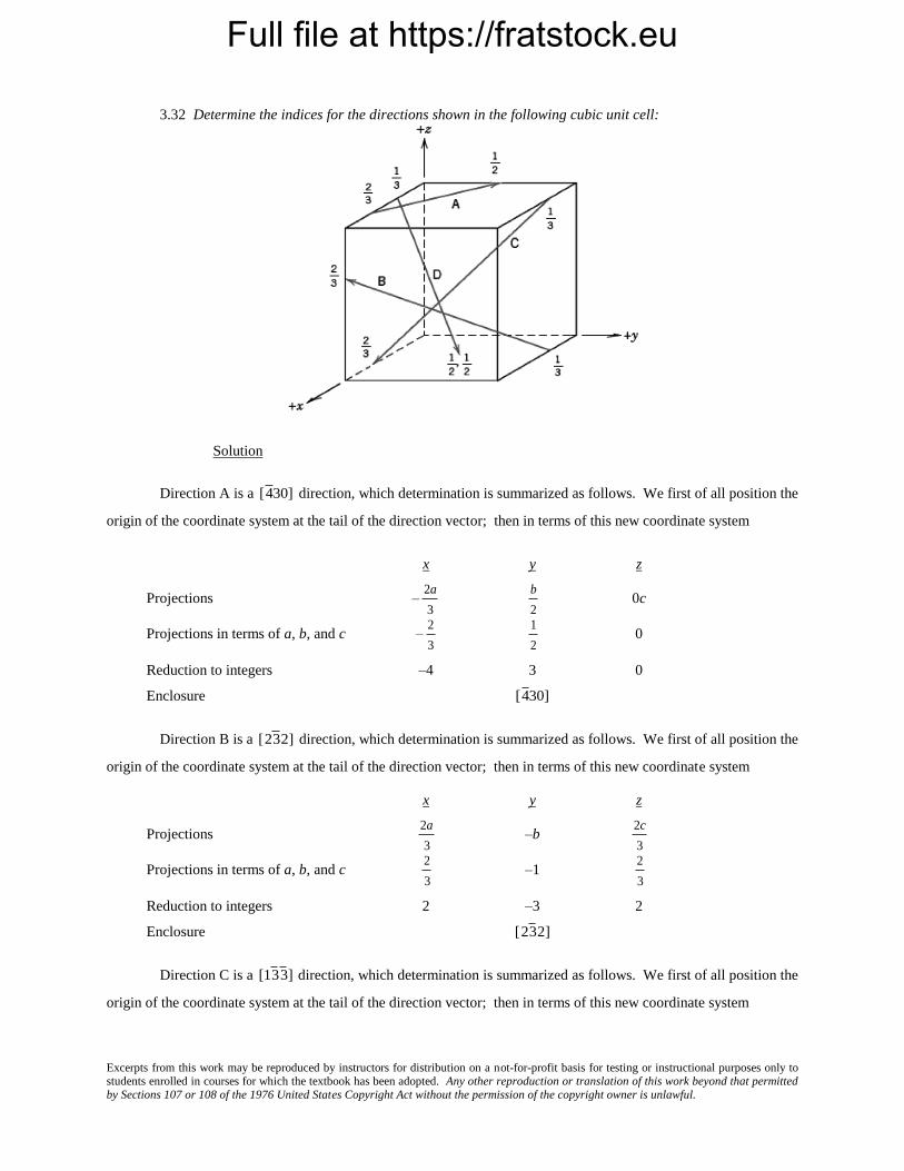
3.32 Determine the indices for the directions shown in the following cubic unit cell:
Solution
Direction A is a
[4 30] direction, which determination is summarized as follows. We first of all position the
origin of the coordinate system at the tail of the direction vector; then in terms of this new coordinate system
x y z
Projections –
2a
3
b
2 0c
Projections in terms of a, b, and c –
2
3
1
2 0
Reduction to integers –4 3 0
Enclosure
[4 30]
Direction B is a
[23 2] direction, which determination is summarized as follows. We first of all position the
origin of the coordinate system at the tail of the direction vector; then in terms of this new coordinate system x y z
Projections
2a
3 –b
2c
3
Projections in terms of a, b, and c
2
3 –1
2
3
Reduction to integers 2 –3 2
Enclosure
[23 2]
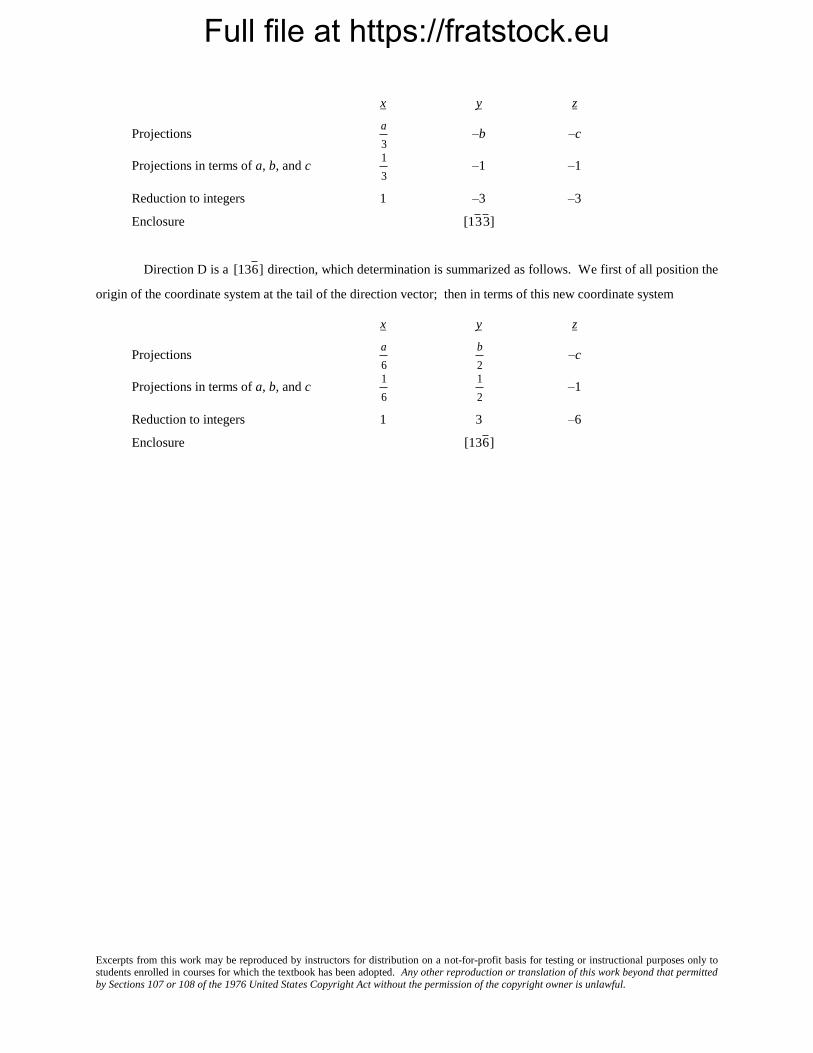
Direction C is a
[13 3 ] direction, which determination is summarized as follows. We first of all position the
origin of the coordinate system at the tail of the direction vector; then in terms of this new coordinate system
Full file at https://fratstock.eu
Excerpts from this work may be reproduced by instructors for distribution on a not-for-profit basis for testing or instructional purposes only to students enrolled in courses for which the textbook has been adopted. Any other reproduction or translation of this work beyond that permitted by Sections 107 or 108 of the 1976 United States Copyright Act without the permission of the copyright owner is unlawful.
x y z
Projections
a
3 –b –c
Projections in terms of a, b, and c
1
3 –1 –1
Reduction to integers 1 –3 –3
Enclosure
[13 3 ]
Direction D is a
[136 ] direction, which determination is summarized as follows. We first of all position the
origin of the coordinate system at the tail of the direction vector; then in terms of this new coordinate system x y z
Projections
a
6
b
2 –c
Projections in terms of a, b, and c
1
6
1
2 –1
Reduction to integers 1 3 –6
Enclosure
[136 ]
Full file at https://fratstock.eu
Excerpts from this work may be reproduced by instructors for distribution on a not-for-profit basis for testing or instructional purposes only to students enrolled in courses for which the textbook has been adopted. Any other reproduction or translation of this work beyond that permitted by Sections 107 or 108 of the 1976 United States Copyright Act without the permission of the copyright owner is unlawful.
3.33 For tetragonal crystals, cite the indices of directions that are equivalent to each of the following
directions:
(a) [001]
(b) [110]
(c) [010]
Solution
For tetragonal crystals a = b ≠ c and = = = 90; therefore, projections along the x and y axes are
equivalent, which are not equivalent to projections along the z axis.
(a) Therefore, for the [001] direction, there is only one equivalent direction:
[001 ].
(b) For the [110] direction, equivalent directions are as follows:
[1 1 0] ,
[1 10] , and
[11 0]
(b) Also, for the [010] direction, equivalent directions are the following:
[01 0] ,
[100] , and
[1 00] .

Full file at https://fratstock.eu
Excerpts from this work may be reproduced by instructors for distribution on a not-for-profit basis for testing or instructional purposes only to students enrolled in courses for which the textbook has been adopted. Any other reproduction or translation of this work beyond that permitted by Sections 107 or 108 of the 1976 United States Copyright Act without the permission of the copyright owner is unlawful.
3.34 Convert the [100] and [111] directions into the four-index Miller–Bravais scheme for hexagonal unit
cells.
Solution
For [100]
u' = 1,
v' = 0,
w' = 0
From Equations 3.6
u = 1
3(2u' v' ) =
1
3[(2)(1) 0] =
2
3
v = 1
3(2vÕ uÕ) =
1
3[(2)(0) 1] =
1
3
t = (u + v) = 2
3
1
3
=
1
3
w = w' = 0
It is necessary to multiply these numbers by 3 in order to reduce them to the lowest set of integers. Thus, the
direction is represented as [uvtw] =
[21 1 0] .
For [111], u' = 1, v' = 1, and w' = 1; therefore,
u = 1
3[(2)(1) 1] =
1
3
v = 1
3[(2)(1) 1] =
1
3
t =
1
3
1
3
2
3
w = 1

Full file at https://fratstock.eu
Excerpts from this work may be reproduced by instructors for distribution on a not-for-profit basis for testing or instructional purposes only to students enrolled in courses for which the textbook has been adopted. Any other reproduction or translation of this work beyond that permitted by Sections 107 or 108 of the 1976 United States Copyright Act without the permission of the copyright owner is unlawful.
If we again multiply these numbers by 3, then u = 1, v = 1, t = -2, and w = 3. Thus, the direction is represented as
Thus, the direction is represented as [uvtw] =
[112 3] .

Full file at https://fratstock.eu
Excerpts from this work may be reproduced by instructors for distribution on a not-for-profit basis for testing or instructional purposes only to students enrolled in courses for which the textbook has been adopted. Any other reproduction or translation of this work beyond that permitted by Sections 107 or 108 of the 1976 United States Copyright Act without the permission of the copyright owner is unlawful.
3.35 Determine indices for the directions shown in the following hexagonal unit cells:
Solution
(a) For this direction, projections on the a1, a2, and z axes are a, a/2, and c/2, or, in terms of a and c the
projections are 1, 1/2, and 1/2, which when multiplied by the factor 2 become the smallest set of integers: 2, 1, and
1. This means that
u’ = 2
v’ = 1
w’ = 1
Now, from Equations 3.6, the u, v, t, and w indices become
u =1
3(2u' v' )
1
3(2)(2) (1)
3
3 1
v =1
3(2vÕ uÕ)
1
3(2)(1) (2) 0
t (u v) 1 0 1
w = w’ = 1
No reduction is necessary inasmuch as all of these indices are integers; therefore, this direction in the four-index
scheme is
[101 1]

Full file at https://fratstock.eu
Excerpts from this work may be reproduced by instructors for distribution on a not-for-profit basis for testing or instructional purposes only to students enrolled in courses for which the textbook has been adopted. Any other reproduction or translation of this work beyond that permitted by Sections 107 or 108 of the 1976 United States Copyright Act without the permission of the copyright owner is unlawful.
(b) For this direction, projections on the a1, a2, and z axes are a/2, a, and 0c, or, in terms of a and c the
projections are 1/2, 1, and 0, which when multiplied by the factor 2 become the smallest set of integers: 1, 2, and 0
This means that
u’ = 1
v’ = 2
w’ = 0
Now, from Equations 3.6, the u, v, t, and w indices become
u 1
3(2u' v)
1
3(2)(1) 2 0
v 1
3(2v' u' )
1
3(2)(2) 1 1
t (uv) 0 1 1
w w' 0
No reduction is necessary inasmuch as all of these indices are integers; therefore, this direction in the four-index
scheme is
[011 0] .

Full file at https://fratstock.eu
Excerpts from this work may be reproduced by instructors for distribution on a not-for-profit basis for testing or instructional purposes only to students enrolled in courses for which the textbook has been adopted. Any other reproduction or translation of this work beyond that permitted by Sections 107 or 108 of the 1976 United States Copyright Act without the permission of the copyright owner is unlawful.
(c) For this direction projections on the a1, a2, and z axes are a, a, and c/2, or, in terms of a and c the
projections are 1, 1, and 1/2, which when multiplied by the factor 2 become the smallest set of integers: 2, 2,
and 1. This means that
u’ = 2
v’ = 2
w’ = 1
Now, from Equations 3.6, the u, v, t, and w indices become
u 1
3(2u' v)
1
3(2)(2) (2)
2
3
v 1
3(2v' u' )
1
3(2)(2) (2)
2
3
t (u v) 2
3
2
3
4
3
w w' 1
Now, in order to get the lowest set of integers, it is necessary to multiply all indices by the factor 3, with the result
that this direction is a
[2 2 43] direction.

Full file at https://fratstock.eu
Excerpts from this work may be reproduced by instructors for distribution on a not-for-profit basis for testing or instructional purposes only to students enrolled in courses for which the textbook has been adopted. Any other reproduction or translation of this work beyond that permitted by Sections 107 or 108 of the 1976 United States Copyright Act without the permission of the copyright owner is unlawful.
(d) For this direction, projections on the a1, a2, and z axes are 0a, a, and 0c, or, in terms of a and c the
projections are 0, -1, and 0. This means that
u’ = 0
v’ = 1
w’ = 0
Now, from Equations 3.6, the u, v, t, and w indices become
u 1
3(2u' v' )
1
3(2)(0) (1)
1
3
v 1
3(2v' u' )
1
3(2)(1) 0
2
3
t (u v) 1
3
2
3
1
3
w wÕ 0
Now, in order to get the lowest set of integers, it is necessary to multiply all indices by the factor 3, with the result
that this is a
[12 10] direction.

Full file at https://fratstock.eu
Excerpts from this work may be reproduced by instructors for distribution on a not-for-profit basis for testing or instructional purposes only to students enrolled in courses for which the textbook has been adopted. Any other reproduction or translation of this work beyond that permitted by Sections 107 or 108 of the 1976 United States Copyright Act without the permission of the copyright owner is unlawful.
3.36 Sketch the
[1 1 23] and
[101 0] directions in a hexagonal unit cell.
Solution
The first portion of this problem asks that we plot the
[1 1 23] within a hexagonal unit cell. Below is shown
this direction plotted within a hexagonal unit cell having a reduced-scale coordinate scheme.
For this direction, projections on the a1, a2, a3, and c axes are respectively, 1, 1, 2, and 3, respectively. In plotting
this direction, we begin at the origin of the coordinate system, point o. From here we proceed 1 unit distance along
the a1 axis (to point p), from here 1 unit distance parallel to a2 axis (to point q), then 2 unit distances parallel (or
along) the a3 axis (to point r), and finally, 3 unit distances parallel to the z axis (to point s). Thus, the
[1 1 23]
direction is that vector that extends from point o to point s as shown.
Now we are asked to plot the
[101 0] within a hexagonal unit cell. In the figure below is plotted this
direction within a hexagonal unit cell having a reduced-scale coordinate scheme.

Full file at https://fratstock.eu
Excerpts from this work may be reproduced by instructors for distribution on a not-for-profit basis for testing or instructional purposes only to students enrolled in courses for which the textbook has been adopted. Any other reproduction or translation of this work beyond that permitted by Sections 107 or 108 of the 1976 United States Copyright Act without the permission of the copyright owner is unlawful.
For this direction, projections on the a1, a2, a3, and c axes are respectively, 1, 0, 1, and 0, respectively. In plotting
this direction, we begin at the origin of the coordinate system, point o. From here we proceed 1 unit distance along
the a1 axis (to point p). Since there is no projection on the a2 axis it is not necessary to move parallel to this axis.
Therefore, from point p we proceed 1 unit distance parallel to a3 axis (to point q). And, finally, inasmuch as there
is no projection along the z axis, it is not necessary to move parallel to this axis. Thus, the
[101 0] direction is that
vector that extends from point o to point q as shown.
Full file at https://fratstock.eu
Excerpts from this work may be reproduced by instructors for distribution on a not-for-profit basis for testing or instructional purposes only to students enrolled in courses for which the textbook has been adopted. Any other reproduction or translation of this work beyond that permitted by Sections 107 or 108 of the 1976 United States Copyright Act without the permission of the copyright owner is unlawful.
3.37 Using Equations 3.6a, 3.6b, 3.6c, and 3.6d, derive expressions for each of the three primed indices
set (u′, v′, and w′) in terms of the four unprimed indices (u, v, t, and w).
Solution
It is first necessary to do an expansion of Equation 3.6a as
u 1
3(2u' v)
2u'
3
v'
3
And solving this expression for v’ yields
v' 2u' 3u
Now, substitution of this expression into Equation 3.6b gives
v 1
3(2vÕ uÕ)
1
3(2)(2uÕ 3u) uÕ uÕ 2u
Or
u' v 2u
And, solving for v from Equation 3.6c leads to
v (u t)
which, when substituted into the above expression for u’ yields
u' v 2u u t 2u u t
In solving for an expression for v’, we begin with the one of the above expressions for this parameter—i.e.,
v' 2u' 3u
Now, substitution of the above expression for u’ into this equation leads to
vÕ 2uÕ 3u (2)(u t) 3u u 2t
Full file at https://fratstock.eu
Excerpts from this work may be reproduced by instructors for distribution on a not-for-profit basis for testing or instructional purposes only to students enrolled in courses for which the textbook has been adopted. Any other reproduction or translation of this work beyond that permitted by Sections 107 or 108 of the 1976 United States Copyright Act without the permission of the copyright owner is unlawful.
And solving for u from Equation 3.6c gives
u v t
which, when substituted in the previous equation results in the following expression for v’
vÕ u 2t ( v t) 2t v t
And, of course from Equation 3.6d
w’ = w
Full file at https://fratstock.eu
Excerpts from this work may be reproduced by instructors for distribution on a not-for-profit basis for testing or instructional purposes only to students enrolled in courses for which the textbook has been adopted. Any other reproduction or translation of this work beyond that permitted by Sections 107 or 108 of the 1976 United States Copyright Act without the permission of the copyright owner is unlawful.
Crystallographic Planes
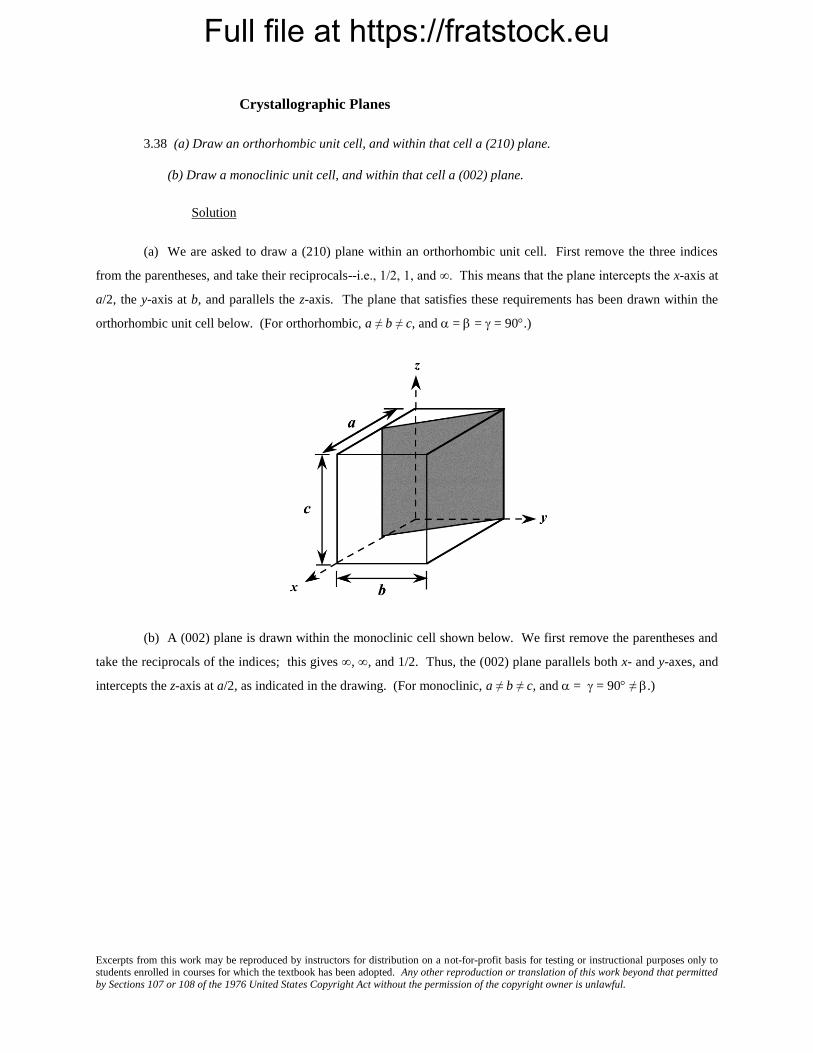
3.38 (a) Draw an orthorhombic unit cell, and within that cell a (210) plane.
(b) Draw a monoclinic unit cell, and within that cell a (002) plane.
Solution
(a) We are asked to draw a (210) plane within an orthorhombic unit cell. First remove the three indices
from the parentheses, and take their reciprocals--i.e., 1/2, 1, and ∞. This means that the plane intercepts the x-axis at
a/2, the y-axis at b, and parallels the z-axis. The plane that satisfies these requirements has been drawn within the
orthorhombic unit cell below. (For orthorhombic, a ≠ b ≠ c, and = = = 90.)
(b) A (002) plane is drawn within the monoclinic cell shown below. We first remove the parentheses and
take the reciprocals of the indices; this gives , , and 1/2. Thus, the (002) plane parallels both x- and y-axes, and
intercepts the z-axis at a/2, as indicated in the drawing. (For monoclinic, a ≠ b ≠ c, and = = 90 ≠ .)

Full file at https://fratstock.eu
Excerpts from this work may be reproduced by instructors for distribution on a not-for-profit basis for testing or instructional purposes only to students enrolled in courses for which the textbook has been adopted. Any other reproduction or translation of this work beyond that permitted by Sections 107 or 108 of the 1976 United States Copyright Act without the permission of the copyright owner is unlawful.
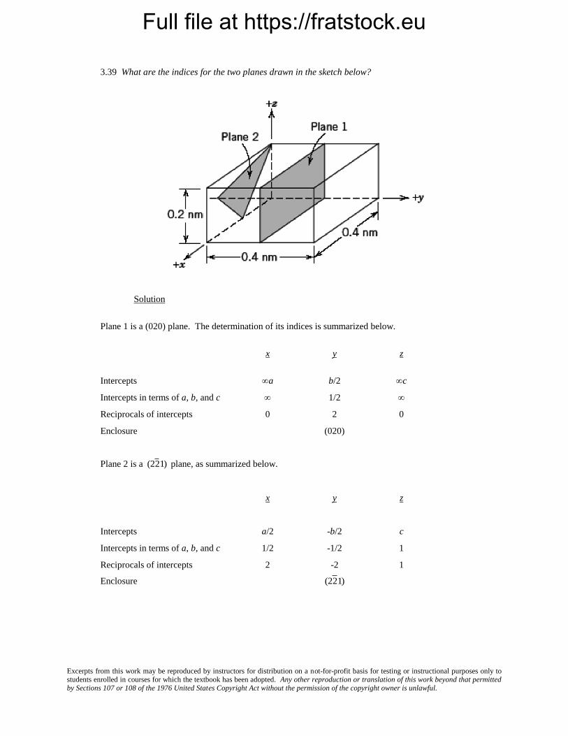
3.39 What are the indices for the two planes drawn in the sketch below?
Solution
Plane 1 is a (020) plane. The determination of its indices is summarized below.
x y z
Intercepts a b/2 c
Intercepts in terms of a, b, and c 1/2
Reciprocals of intercepts 0 2 0
Enclosure (020)
Plane 2 is a
(22 1) plane, as summarized below.
x y z
Intercepts a/2 -b/2 c
Intercepts in terms of a, b, and c 1/2 -1/2 1
Reciprocals of intercepts 2 -2 1
Enclosure
(22 1)
Full file at https://fratstock.eu
Excerpts from this work may be reproduced by instructors for distribution on a not-for-profit basis for testing or instructional purposes only to students enrolled in courses for which the textbook has been adopted. Any other reproduction or translation of this work beyond that permitted by Sections 107 or 108 of the 1976 United States Copyright Act without the permission of the copyright owner is unlawful.
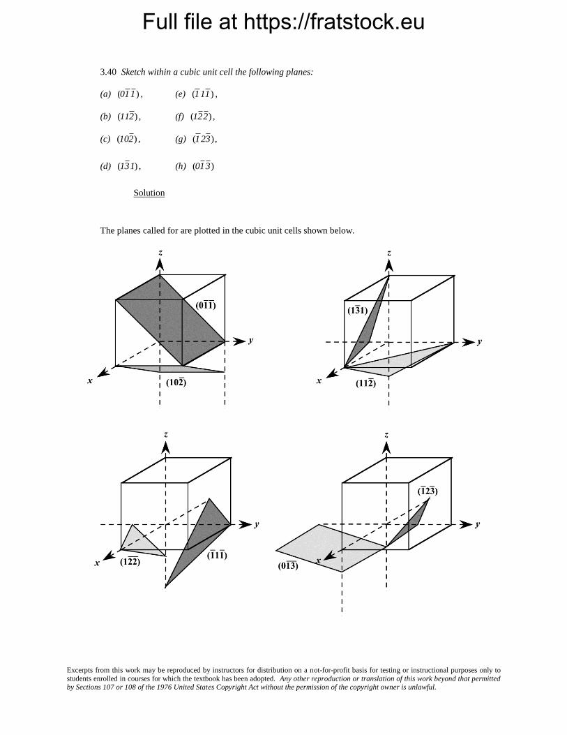
3.40 Sketch within a cubic unit cell the following planes:
(a)
(01 1 ) , (e)
(1 11 ) ,
(b)
(112 ) , (f)
(12 2 ) ,
(c)
(102 ) , (g)
(1 23 ) ,
(d)
(13 1) , (h)
(01 3 )
Solution
The planes called for are plotted in the cubic unit cells shown below.
Full file at https://fratstock.eu
Excerpts from this work may be reproduced by instructors for distribution on a not-for-profit basis for testing or instructional purposes only to students enrolled in courses for which the textbook has been adopted. Any other reproduction or translation of this work beyond that permitted by Sections 107 or 108 of the 1976 United States Copyright Act without the permission of the copyright owner is unlawful.
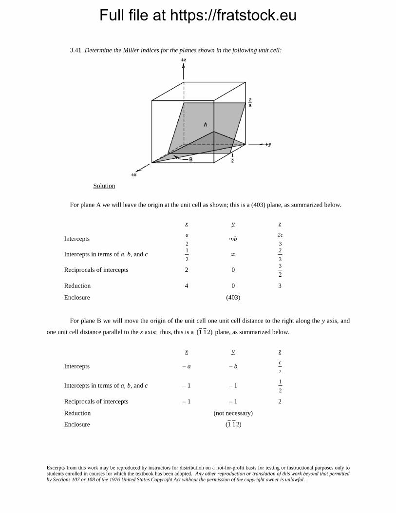
3.41 Determine the Miller indices for the planes shown in the following unit cell:
Solution
For plane A we will leave the origin at the unit cell as shown; this is a (403) plane, as summarized below.
x y z
Intercepts
a
2 b
2c
3
Intercepts in terms of a, b, and c
1
2
2
3
Reciprocals of intercepts 2 0
3
2
Reduction 4 0 3
Enclosure (403)
For plane B we will move the origin of the unit cell one unit cell distance to the right along the y axis, and
one unit cell distance parallel to the x axis; thus, this is a
(1 1 2) plane, as summarized below.
x y z
Intercepts – a – b
c
2
Intercepts in terms of a, b, and c – 1 – 1
1
2
Reciprocals of intercepts – 1 – 1 2
Reduction (not necessary)
Enclosure
(1 1 2)

Full file at https://fratstock.eu
Excerpts from this work may be reproduced by instructors for distribution on a not-for-profit basis for testing or instructional purposes only to students enrolled in courses for which the textbook has been adopted. Any other reproduction or translation of this work beyond that permitted by Sections 107 or 108 of the 1976 United States Copyright Act without the permission of the copyright owner is unlawful.
3.42 Determine the Miller indices for the planes shown in the following unit cell:
Solution
For plane A we will move the origin of the coordinate system one unit cell distance to the upward along the
z axis; thus, this is a
(322 ) plane, as summarized below.
x y z
Intercepts
a
3
b
2 –
c
2
Intercepts in terms of a, b, and c
1
3
1
2 –
1
2
Reciprocals of intercepts 3 2 – 2
Reduction (not necessary)
Enclosure
(322 )
For plane B we will move the original of the coordinate system on unit cell distance along the x axis; thus,
this is a
(1 01) plane, as summarized below.
x y z
Intercepts –
a
2 b
c
2
Intercepts in terms of a, b, and c –
1
2
1
2
Reciprocals of intercepts – 2 0 2
Reduction – 1 0 1
Enclosure
(1 01)
Full file at https://fratstock.eu
Excerpts from this work may be reproduced by instructors for distribution on a not-for-profit basis for testing or instructional purposes only to students enrolled in courses for which the textbook has been adopted. Any other reproduction or translation of this work beyond that permitted by Sections 107 or 108 of the 1976 United States Copyright Act without the permission of the copyright owner is unlawful.
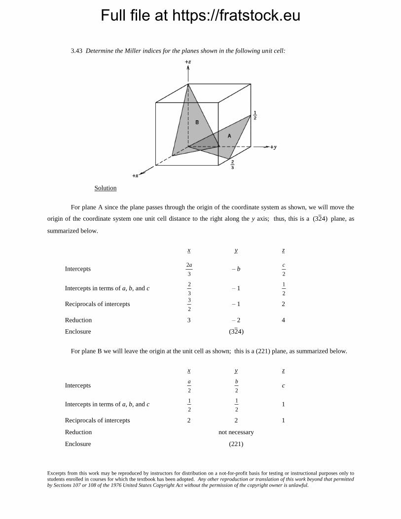
3.43 Determine the Miller indices for the planes shown in the following unit cell:
Solution
For plane A since the plane passes through the origin of the coordinate system as shown, we will move the
origin of the coordinate system one unit cell distance to the right along the y axis; thus, this is a
(32 4) plane, as
summarized below.
x y z
Intercepts
2a
3 – b
c
2
Intercepts in terms of a, b, and c
2
3 – 1
1
2
Reciprocals of intercepts
3
2 – 1 2
Reduction 3 – 2 4
Enclosure
(32 4)
For plane B we will leave the origin at the unit cell as shown; this is a (221) plane, as summarized below.
x y z
Intercepts
a
2
b
2 c
Intercepts in terms of a, b, and c
1
2
1
2 1
Reciprocals of intercepts 2 2 1
Reduction not necessary
Enclosure (221)

Full file at https://fratstock.eu
Excerpts from this work may be reproduced by instructors for distribution on a not-for-profit basis for testing or instructional purposes only to students enrolled in courses for which the textbook has been adopted. Any other reproduction or translation of this work beyond that permitted by Sections 107 or 108 of the 1976 United States Copyright Act without the permission of the copyright owner is unlawful.
3.44 Cite the indices of the direction that results from the intersection of each of the following pair of planes
within a cubic crystal: (a) (100) and (010) planes, (b) (111) and
(111 ) planes, and (c)
(101 ) and (001)
planes.
Solution
(a) In the figure below is shown (100) and (010) planes, and, as indicated, their intersection results in a [001],
or equivalently, a
[001 ] direction.
(b) In the figure below is shown (111) and
(111 ) planes, and, as indicated, their intersection results in a
[1 10] , or equivalently, a
[11 0] direction.

Full file at https://fratstock.eu
Excerpts from this work may be reproduced by instructors for distribution on a not-for-profit basis for testing or instructional purposes only to students enrolled in courses for which the textbook has been adopted. Any other reproduction or translation of this work beyond that permitted by Sections 107 or 108 of the 1976 United States Copyright Act without the permission of the copyright owner is unlawful.
(c) In the figure below is shown
(101 ) and (001) planes, and, as indicated, their intersection results in a
[010], or equivalently, a
[01 0] direction.

Full file at https://fratstock.eu
Excerpts from this work may be reproduced by instructors for distribution on a not-for-profit basis for testing or instructional purposes only to students enrolled in courses for which the textbook has been adopted. Any other reproduction or translation of this work beyond that permitted by Sections 107 or 108 of the 1976 United States Copyright Act without the permission of the copyright owner is unlawful.
3.45 Sketch the atomic packing of (a) the (100) plane for the BCC crystal structure, and (b) the (201)
plane for the FCC crystal structure (similar to Figures 3.10b and 3.11b).
Solution
(a) A BCC unit cell, its (100) plane, and the atomic packing of this plane are indicated below.
Corresponding atom positions in the two drawings are indicated by letters W, X, Y, and Z.
(b) An FCC unit cell, its (201) plane, and the atomic packing of this plane are indicated below.
Corresponding atom positions in the two drawing are indicated by the letters A, B, and C.

Full file at https://fratstock.eu
Excerpts from this work may be reproduced by instructors for distribution on a not-for-profit basis for testing or instructional purposes only to students enrolled in courses for which the textbook has been adopted. Any other reproduction or translation of this work beyond that permitted by Sections 107 or 108 of the 1976 United States Copyright Act without the permission of the copyright owner is unlawful.
3.46 Consider the reduced-sphere unit cell shown in Problem 3.20, having an origin of the coordinate
system positioned at the atom labeled with an O. For the following sets of planes, determine which are equivalent:
(a)
(001 ) , (010), and,
(1 00)
(b)
(11 0) ,
(101 ) ,
(01 1) , and
(1 1 0)
(c)
(1 1 1 ) ,
(1 11 ) ,
(1 1 1) , and
(11 1)
Solution
(a) The unit cell in Problem 3.20 is body-centered tetragonal. Of the three planes given in the problem
statement the
(1 00) and (010) are equivalent—that is, have the same atomic packing. The atomic packing for these
two planes as well as the
(001 ) are shown in the figure below.
(b) Of the four planes cited in the problem statement,
(11 0) and
(1 1 0) are equivalent to one another—
have the same atomic packing. The atomic arrangement of these planes is shown in the left drawing below.
Full file at https://fratstock.eu
Excerpts from this work may be reproduced by instructors for distribution on a not-for-profit basis for testing or instructional purposes only to students enrolled in courses for which the textbook has been adopted. Any other reproduction or translation of this work beyond that permitted by Sections 107 or 108 of the 1976 United States Copyright Act without the permission of the copyright owner is unlawful.
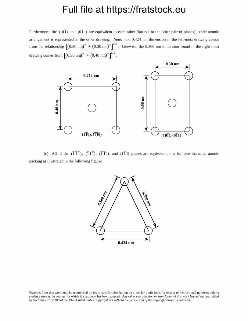
Furthermore, the
(101 ) and
(01 1) are equivalent to each other (but not to the other pair of planes); their atomic
arrangement is represented in the other drawing. Note: the 0.424 nm dimension in the left-most drawing comes
from the relationship
(0.30 nm)2 + (0.30 nm)2 1/ 2
. Likewise, the 0.500 nm dimension found in the right-most
drawing comes from
(0.30 nm)2 + (0.40 nm)2 1/ 2
.
(c) All of the
(1 1 1 ) ,
(1 11 ) ,
(1 1 1) , and
(11 1) planes are equivalent, that is, have the same atomic
packing as illustrated in the following figure:

Full file at https://fratstock.eu
Excerpts from this work may be reproduced by instructors for distribution on a not-for-profit basis for testing or instructional purposes only to students enrolled in courses for which the textbook has been adopted. Any other reproduction or translation of this work beyond that permitted by Sections 107 or 108 of the 1976 United States Copyright Act without the permission of the copyright owner is unlawful.
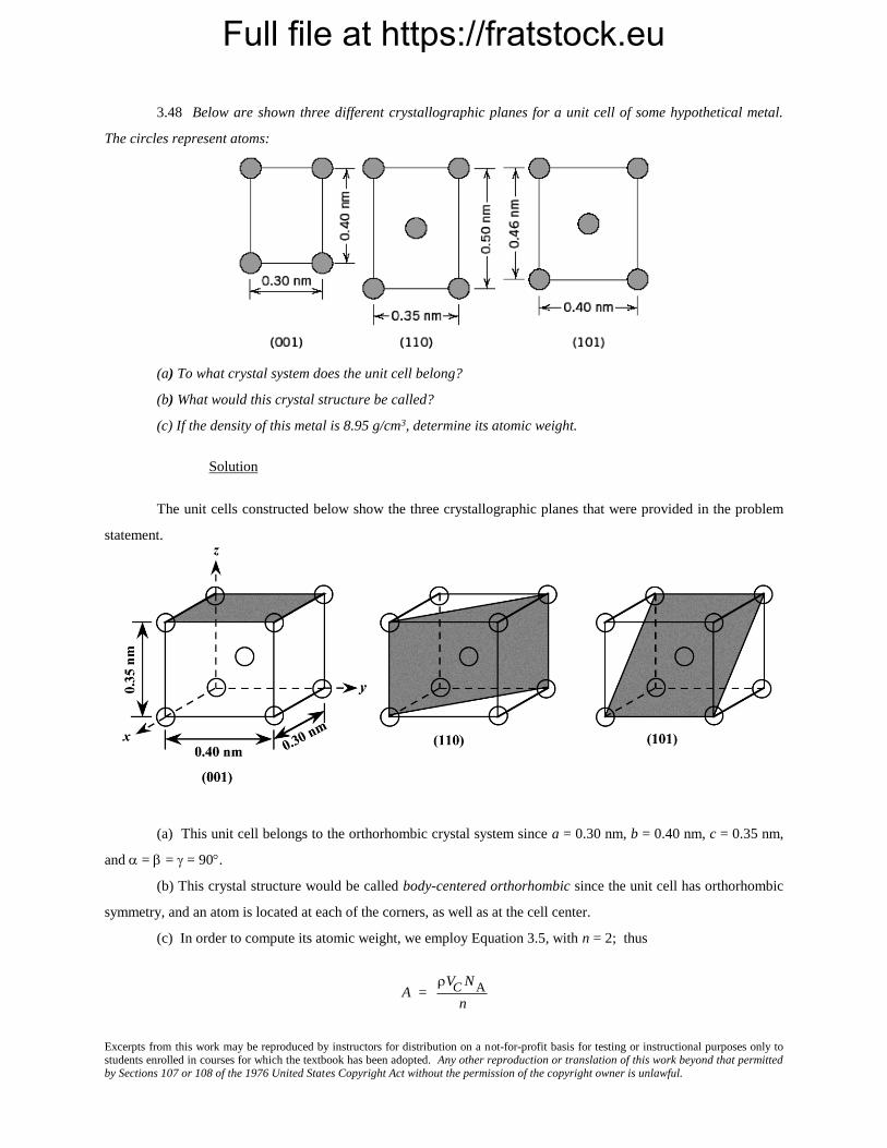
3.47 Here are shown the atomic packing schemes for several different crystallographic directions for some
hypothetical metal. For each direction the circles represent only those atoms contained within a unit cell, which
circles are reduced from their actual size.
(a) To what crystal system does the unit cell belong?
(b) What would this crystal structure be called? Solution
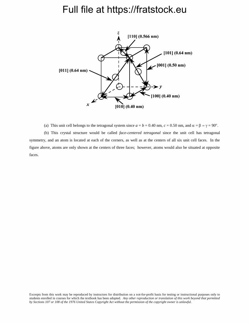
Below is constructed a unit cell using the six crystallographic directions that were provided in the problem.
Full file at https://fratstock.eu
Excerpts from this work may be reproduced by instructors for distribution on a not-for-profit basis for testing or instructional purposes only to students enrolled in courses for which the textbook has been adopted. Any other reproduction or translation of this work beyond that permitted by Sections 107 or 108 of the 1976 United States Copyright Act without the permission of the copyright owner is unlawful.
(a) This unit cell belongs to the tetragonal system since a = b = 0.40 nm, c = 0.50 nm, and = = 90.
(b) This crystal structure would be called face-centered tetragonal since the unit cell has tetragonal
symmetry, and an atom is located at each of the corners, as well as at the centers of all six unit cell faces. In the
figure above, atoms are only shown at the centers of three faces; however, atoms would also be situated at opposite
faces.
Full file at https://fratstock.eu
Excerpts from this work may be reproduced by instructors for distribution on a not-for-profit basis for testing or instructional purposes only to students enrolled in courses for which the textbook has been adopted. Any other reproduction or translation of this work beyond that permitted by Sections 107 or 108 of the 1976 United States Copyright Act without the permission of the copyright owner is unlawful.
3.48 Below are shown three different crystallographic planes for a unit cell of some hypothetical metal.
The circles represent atoms:
(a) To what crystal system does the unit cell belong?
(b) What would this crystal structure be called?
(c) If the density of this metal is 8.95 g/cm3, determine its atomic weight.
Solution
The unit cells constructed below show the three crystallographic planes that were provided in the problem
statement.
(a) This unit cell belongs to the orthorhombic crystal system since a = 0.30 nm, b = 0.40 nm, c = 0.35 nm,
and = = = 90.
(b) This crystal structure would be called body-centered orthorhombic since the unit cell has orthorhombic
symmetry, and an atom is located at each of the corners, as well as at the cell center.
(c) In order to compute its atomic weight, we employ Equation 3.5, with n = 2; thus
A = VC N A
n

Full file at https://fratstock.eu
Excerpts from this work may be reproduced by instructors for distribution on a not-for-profit basis for testing or instructional purposes only to students enrolled in courses for which the textbook has been adopted. Any other reproduction or translation of this work beyond that permitted by Sections 107 or 108 of the 1976 United States Copyright Act without the permission of the copyright owner is unlawful.
(8.95 g/cm3) (3.0)(4.0)(3.5) ( 10-24 cm3/unit cell)(6.022 10 23 atoms/mol)
2 atoms/unit cell
= 113.2 g/mol

Full file at https://fratstock.eu
Excerpts from this work may be reproduced by instructors for distribution on a not-for-profit basis for testing or instructional purposes only to students enrolled in courses for which the textbook has been adopted. Any other reproduction or translation of this work beyond that permitted by Sections 107 or 108 of the 1976 United States Copyright Act without the permission of the copyright owner is unlawful.
3.49 Convert the (010) and (101) planes into the four-index Miller–Bravais scheme for hexagonal unit
cells.
Solution
For (010), h = 0, k = 1, and l = 0, and, from Equation 3.7, the value of i is equal to
i (h k) (0 1) 1
Therefore, the (010) plane becomes
(011 0) .
Now for the (101) plane, h = 1, k = 0, and l = 1, and computation of i using Equation 3.7 leads to
i (h k) [1 0] 1
such that (101) becomes
(101 1) .

Full file at https://fratstock.eu
Excerpts from this work may be reproduced by instructors for distribution on a not-for-profit basis for testing or instructional purposes only to students enrolled in courses for which the textbook has been adopted. Any other reproduction or translation of this work beyond that permitted by Sections 107 or 108 of the 1976 United States Copyright Act without the permission of the copyright owner is unlawful.
3.50 Determine the indices for the planes shown in the hexagonal unit cells below:
Solution
(a) For this plane, intersections with the a1, a2, and z axes are a, a, and c/2 (the plane parallels both a1
and a2 axes). In terms of a and c these intersections are , , and ½, the respective reciprocals of which are 0, 0,
and 2. This means that
h = 0
k = 0
l = 2
Now, from Equation 3.7, the value of i is
i (h k) [0 0] 0
Hence, this is a
(0002) plane.
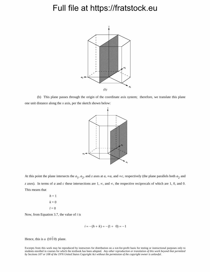
Full file at https://fratstock.eu
Excerpts from this work may be reproduced by instructors for distribution on a not-for-profit basis for testing or instructional purposes only to students enrolled in courses for which the textbook has been adopted. Any other reproduction or translation of this work beyond that permitted by Sections 107 or 108 of the 1976 United States Copyright Act without the permission of the copyright owner is unlawful.
(b) This plane passes through the origin of the coordinate axis system; therefore, we translate this plane
one unit distance along the x axis, per the sketch shown below:
At this point the plane intersects the a1, a2, and z axes at a, a, and c, respectively (the plane parallels both a2 and
z axes). In terms of a and c these intersections are 1, , and , the respective reciprocals of which are 1, 0, and 0.
This means that
h = 1
k = 0
l = 0
Now, from Equation 3.7, the value of i is
i (h k) (1 0) 1
Hence, this is a
(101 0) plane.

Full file at https://fratstock.eu
Excerpts from this work may be reproduced by instructors for distribution on a not-for-profit basis for testing or instructional purposes only to students enrolled in courses for which the textbook has been adopted. Any other reproduction or translation of this work beyond that permitted by Sections 107 or 108 of the 1976 United States Copyright Act without the permission of the copyright owner is unlawful.
(c) For this plane, intersections with the a1, a2, and z axes are –a, a, and c. In terms of a and c these
intersections are –1, 1, and 1, the respective reciprocals of which are 0, 1, and 1. This means that
h = –1
k = 1
l = 1
Now, from Equation 3.7, the value of i is
i (h k) (1 1) 0
Hence, this is a
(1 101) plane.
Full file at https://fratstock.eu
Excerpts from this work may be reproduced by instructors for distribution on a not-for-profit basis for testing or instructional purposes only to students enrolled in courses for which the textbook has been adopted. Any other reproduction or translation of this work beyond that permitted by Sections 107 or 108 of the 1976 United States Copyright Act without the permission of the copyright owner is unlawful.
(d) For this plane, intersections with the a1, a2, and z axes are –a/2, a, and c/2, respectively. In terms of a
and c these intersections are –1/2, 1, and 1/2, the respective reciprocals of which are –2, 1, and 2. This means that
h = –2
k = 1
l = 2
Now, from Equation 3.7, the value of i is
i (h k) (2 1) 1
Therefore, this is a
(2 112) plane.

Full file at https://fratstock.eu
Excerpts from this work may be reproduced by instructors for distribution on a not-for-profit basis for testing or instructional purposes only to students enrolled in courses for which the textbook has been adopted. Any other reproduction or translation of this work beyond that permitted by Sections 107 or 108 of the 1976 United States Copyright Act without the permission of the copyright owner is unlawful.
3.51 Sketch the
(11 01) and
(112 0) planes in a hexagonal unit cell.
Solution
For
(11 01) the reciprocals of h, k, i, and l are, respectively, 1, –1, , and 1; thus, this plane is parallel to
the a3 axis, and intersects the a1 axis at a, the a2 axis at –a, and the z-axis at c. The plane having these intersections
is shown in the figure below
For
(112 0) the reciprocals of h, k, i, and l are, respectively, 1, 1, –1/2, and ; thus, this plane is parallel to
the z axis, and intersects the a1 axis at a, the a2 axis at a, and the a3 axis at –a/2. The plane having these
intersections is shown in the figure below.

Full file at https://fratstock.eu
Excerpts from this work may be reproduced by instructors for distribution on a not-for-profit basis for testing or instructional purposes only to students enrolled in courses for which the textbook has been adopted. Any other reproduction or translation of this work beyond that permitted by Sections 107 or 108 of the 1976 United States Copyright Act without the permission of the copyright owner is unlawful.
Linear and Planar Densities
3.52 (a) Derive linear density expressions for FCC [100] and [111] directions in terms of the atomic
radius R.
(b) Compute and compare linear density values for these same two directions for silver.
Solution
(a) In the figure below is shown a [100] direction within an FCC unit cell.
For this [100] direction there is one atom at each of the two unit cell corners, and, thus, there is the equivalent of 1
atom that is centered on the direction vector. The length of this direction vector is just the unit cell edge length,
2R 2 (Equation 3.1). Therefore, the expression for the linear density of this plane is
LD100 = number of atoms centered on [100] direction vector
length of [100] direction vector
1 atom
2 R 2
1
2 R 2
An FCC unit cell within which is drawn a [111] direction is shown below.

Full file at https://fratstock.eu
Excerpts from this work may be reproduced by instructors for distribution on a not-for-profit basis for testing or instructional purposes only to students enrolled in courses for which the textbook has been adopted. Any other reproduction or translation of this work beyond that permitted by Sections 107 or 108 of the 1976 United States Copyright Act without the permission of the copyright owner is unlawful.
For this [111] direction, the vector shown passes through only the centers of the single atom at each of its ends, and,
thus, there is the equivalence of 1 atom that is centered on the direction vector. The length of this direction vector is
denoted by z in this figure, which is equal to
z x2 y2
where x is the length of the bottom face diagonal, which is equal to 4R. Furthermore, y is the unit cell edge length,
which is equal to
2R 2 (Equation 3.1). Thus, using the above equation, the length z may be calculated as follows:
z (4R)2 (2R 2)2 24R2 2R 6
Therefore, the expression for the linear density of this direction is
LD111 = number of atoms centered on [111] direction vector
length of [111] direction vector
1 atom
2 R 6
1
2 R 6
(b) From the table inside the front cover, the atomic radius for silver is 0.144 nm. Therefore, the linear
density for the [100] direction is
LD100 (Ag) 1
2 R 2
1
(2)(0.144 nm) 2 2.46 nm1 2.46 109 m1
While for the [111] direction
LD111(Ag) 1
2 R 6
1
(2)(0.144 nm) 6 1.42 nm1 1.42 109 m1

Full file at https://fratstock.eu
Excerpts from this work may be reproduced by instructors for distribution on a not-for-profit basis for testing or instructional purposes only to students enrolled in courses for which the textbook has been adopted. Any other reproduction or translation of this work beyond that permitted by Sections 107 or 108 of the 1976 United States Copyright Act without the permission of the copyright owner is unlawful.
3.53 (a) Derive linear density expressions for BCC [110] and [111] directions in terms of the atomic
radius R.
(b) Compute and compare linear density values for these same two directions for tungsten.
Solution
(a) In the figure below is shown a [110] direction within a BCC unit cell.
For this [110] direction there is one atom at each of the two unit cell corners, and, thus, there is the equivalence of 1
atom that is centered on the direction vector. The length of this direction vector is denoted by x in this figure, which
is equal to
x z2 y2
where y is the unit cell edge length, which, from Equation 3.3 is equal to
4 R
3. Furthermore, z is the length of the
unit cell diagonal, which is equal to 4R Thus, using the above equation, the length x may be calculated as follows:
x (4R)2 4 R
3
2
32 R2
3 4 R
2
3
Therefore, the expression for the linear density of this direction is
LD110 = number of atoms centered on [110] direction vector
length of [110] direction vector
1 atom
4 R2
3
3
4 R 2

Full file at https://fratstock.eu
Excerpts from this work may be reproduced by instructors for distribution on a not-for-profit basis for testing or instructional purposes only to students enrolled in courses for which the textbook has been adopted. Any other reproduction or translation of this work beyond that permitted by Sections 107 or 108 of the 1976 United States Copyright Act without the permission of the copyright owner is unlawful.
A BCC unit cell within which is drawn a [111] direction is shown below.
For although the [111] direction vector shown passes through the centers of three atoms, there is an equivalence of
only two atoms associated with this unit cell—one-half of each of the two atoms at the end of the vector, in addition
to the center atom belongs entirely to the unit cell. Furthermore, the length of the vector shown is equal to 4R, since
all of the atoms whose centers the vector passes through touch one another. Therefore, the linear density is equal to
LD111 = number of atoms centered on [111] direction vector
length of [111] direction vector
2 atoms
4R
1
2R
(b) From the table inside the front cover, the atomic radius for tungsten is 0.137 nm. Therefore, the linear
density for the [110] direction is
LD110 (W) 3
4 R 2
3
(4)(0.137 nm) 2 2.23 nm1 2.23 109 m1
While for the [111] direction
LD111(W) 1
2 R
1
(2)(0.137 nm) 3.65 nm1 3.65 109 m1
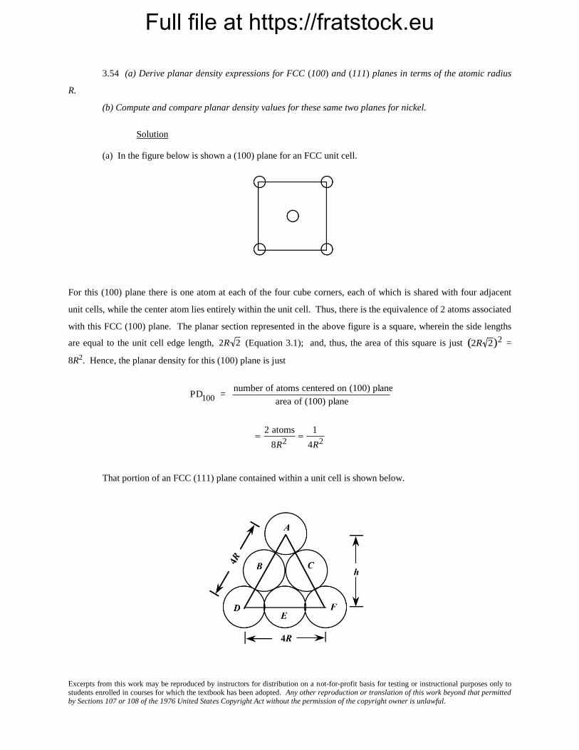
Full file at https://fratstock.eu
Excerpts from this work may be reproduced by instructors for distribution on a not-for-profit basis for testing or instructional purposes only to students enrolled in courses for which the textbook has been adopted. Any other reproduction or translation of this work beyond that permitted by Sections 107 or 108 of the 1976 United States Copyright Act without the permission of the copyright owner is unlawful.
3.54 (a) Derive planar density expressions for FCC (100) and (111) planes in terms of the atomic radius
R.
(b) Compute and compare planar density values for these same two planes for nickel.
Solution
(a) In the figure below is shown a (100) plane for an FCC unit cell.
For this (100) plane there is one atom at each of the four cube corners, each of which is shared with four adjacent
unit cells, while the center atom lies entirely within the unit cell. Thus, there is the equivalence of 2 atoms associated
with this FCC (100) plane. The planar section represented in the above figure is a square, wherein the side lengths
are equal to the unit cell edge length,
2R 2 (Equation 3.1); and, thus, the area of this square is just
(2R 2)2 =
8R2. Hence, the planar density for this (100) plane is just
PD100 = number of atoms centered on (100) plane
area of (100) plane
2 atoms
8R2
1
4R2
That portion of an FCC (111) plane contained within a unit cell is shown below.

Full file at https://fratstock.eu
Excerpts from this work may be reproduced by instructors for distribution on a not-for-profit basis for testing or instructional purposes only to students enrolled in courses for which the textbook has been adopted. Any other reproduction or translation of this work beyond that permitted by Sections 107 or 108 of the 1976 United States Copyright Act without the permission of the copyright owner is unlawful.
There are six atoms whose centers lie on this plane, which are labeled A through F. One-sixth of each of atoms A, D,
and F are associated with this plane (yielding an equivalence of one-half atom), with one-half of each of atoms B, C,
and E (or an equivalence of one and one-half atoms) for a total equivalence of two atoms. Now, the area of the
triangle shown in the above figure is equal to one-half of the product of the base length and the height, h. If we
consider half of the triangle, then
(2 R)2 h2 (4 R)2
which leads to h =
2R 3 . Thus, the area is equal to
Area 4 R(h)
2
(4 R)(2 R 3)
2 4 R2 3
And, thus, the planar density is
PD111 = number of atoms centered on (111) plane
area of (111) plane
2 atoms
4 R2 3
1
2 R2 3
(b) From the table inside the front cover, the atomic radius for nickel is 0.125 nm. Therefore, the planar
density for the (100) plane is
PD100 (Ni) 1
4 R2
1
4 (0.125 nm)2 16.00 nm2 1.600 1019 m2
While for the (111) plane
PD111(Ni) 1
2 R2 3
1
2 3 (0.125 nm)2 18.48 nm2 1.848 1019 m2
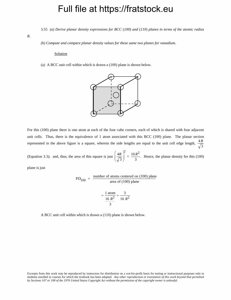
Full file at https://fratstock.eu
Excerpts from this work may be reproduced by instructors for distribution on a not-for-profit basis for testing or instructional purposes only to students enrolled in courses for which the textbook has been adopted. Any other reproduction or translation of this work beyond that permitted by Sections 107 or 108 of the 1976 United States Copyright Act without the permission of the copyright owner is unlawful.
3.55 (a) Derive planar density expressions for BCC (100) and (110) planes in terms of the atomic radius
R.
(b) Compute and compare planar density values for these same two planes for vanadium.
Solution
(a) A BCC unit cell within which is drawn a (100) plane is shown below.
For this (100) plane there is one atom at each of the four cube corners, each of which is shared with four adjacent
unit cells. Thus, there is the equivalence of 1 atom associated with this BCC (100) plane. The planar section
represented in the above figure is a square, wherein the side lengths are equal to the unit cell edge length,
4 R
3
(Equation 3.3); and, thus, the area of this square is just
4R
3
2
=
16 R2
3. Hence, the planar density for this (100)
plane is just
PD100 = number of atoms centered on (100) plane
area of (100) plane
1 atom
16 R2
3
3
16 R2
A BCC unit cell within which is drawn a (110) plane is shown below.
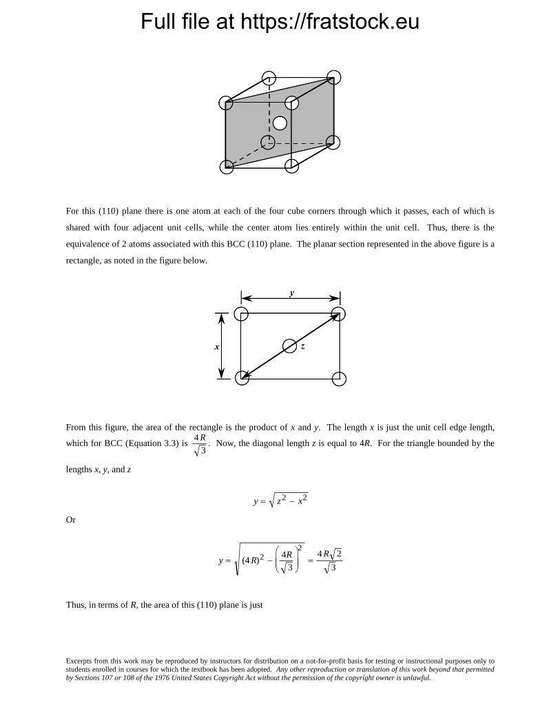
Full file at https://fratstock.eu
Excerpts from this work may be reproduced by instructors for distribution on a not-for-profit basis for testing or instructional purposes only to students enrolled in courses for which the textbook has been adopted. Any other reproduction or translation of this work beyond that permitted by Sections 107 or 108 of the 1976 United States Copyright Act without the permission of the copyright owner is unlawful.
For this (110) plane there is one atom at each of the four cube corners through which it passes, each of which is
shared with four adjacent unit cells, while the center atom lies entirely within the unit cell. Thus, there is the
equivalence of 2 atoms associated with this BCC (110) plane. The planar section represented in the above figure is a
rectangle, as noted in the figure below.
From this figure, the area of the rectangle is the product of x and y. The length x is just the unit cell edge length,
which for BCC (Equation 3.3) is
4 R
3. Now, the diagonal length z is equal to 4R. For the triangle bounded by the
lengths x, y, and z
y z2 x2
Or
y (4 R)2 4R
3
2
4 R 2
3
Thus, in terms of R, the area of this (110) plane is just

Full file at https://fratstock.eu
Excerpts from this work may be reproduced by instructors for distribution on a not-for-profit basis for testing or instructional purposes only to students enrolled in courses for which the textbook has been adopted. Any other reproduction or translation of this work beyond that permitted by Sections 107 or 108 of the 1976 United States Copyright Act without the permission of the copyright owner is unlawful.
Area (110) xy 4 R
3
4 R 2
3
16 R2 2
3
And, finally, the planar density for this (110) plane is just
PD110 = number of atoms centered on (110) plane
area of (110) plane
2 atoms
16 R2 2
3
3
8 R2 2
(b) From the table inside the front cover, the atomic radius for vanadium is 0.132 nm. Therefore, the
planar density for the (100) plane is
PD100 (V) 3
16R2
3
16(0.132 nm)2 10.76 nm2 1.076 1019 m2
While for the (110) plane
PD110 (V) 3
8 R2 2
3
8 (0.132 nm)2 2 15.22 nm2 1.522 1019 m2

Full file at https://fratstock.eu
Excerpts from this work may be reproduced by instructors for distribution on a not-for-profit basis for testing or instructional purposes only to students enrolled in courses for which the textbook has been adopted. Any other reproduction or translation of this work beyond that permitted by Sections 107 or 108 of the 1976 United States Copyright Act without the permission of the copyright owner is unlawful.
3.56 (a) Derive the planar density expression for the HCP (0001) plane in terms of the atomic radius R.
(b) Compute the planar density value for this same plane for magnesium.
Solution
(a) A (0001) plane for an HCP unit cell is show below.
Each of the 6 perimeter atoms in this plane is shared with three other unit cells, whereas the center atom is shared
with no other unit cells; this gives rise to three equivalent atoms belonging to this plane.
In terms of the atomic radius R, the area of each of the 6 equilateral triangles that have been drawn is
R2 3 , or the total area of the plane shown is
6 R2 3 . And the planar density for this (0001) plane is equal to
PD0001 number of atoms centered on (0001) plane
area of (0001) plane
3 atoms
6R2 3
1
2R2 3
(b) From the table inside the front cover, the atomic radius for magnesium is 0.160 nm. Therefore, the
planar density for the (0001) plane is
PD0001(Mg) 1
2 R2 3
1
2 (0.160 nm)2 3 11.28 nm2 1.128 1019 m2

Full file at https://fratstock.eu
Excerpts from this work may be reproduced by instructors for distribution on a not-for-profit basis for testing or instructional purposes only to students enrolled in courses for which the textbook has been adopted. Any other reproduction or translation of this work beyond that permitted by Sections 107 or 108 of the 1976 United States Copyright Act without the permission of the copyright owner is unlawful.
Polycrystalline Materials
3.57 Explain why the properties of polycrystalline materials are most often isotropic.
Solution
Although each individual grain in a polycrystalline material may be anisotropic, if the grains have random
orientations, then the solid aggregate of the many anisotropic grains will behave isotropically.

Full file at https://fratstock.eu
Excerpts from this work may be reproduced by instructors for distribution on a not-for-profit basis for testing or instructional purposes only to students enrolled in courses for which the textbook has been adopted. Any other reproduction or translation of this work beyond that permitted by Sections 107 or 108 of the 1976 United States Copyright Act without the permission of the copyright owner is unlawful.
X-ray Diffraction: Determination of Crystal Structures
3.58 Using the data for molybdenum in Table 3.1, compute the interplanar spacing for the (111) set of
planes.
Solution
From the Table 3.1, molybdenum has a BCC crystal structure and an atomic radius of 0.1363 nm. Using
Equation (3.3), the lattice parameter a may be computed as
a4 R
3
(4)(0.1363 nm)
3 0.3148 nm
Now, the interplanar spacing d111
maybe determined using Equation 3.14 as
d111 =a
(1)2 + (1)2 + (1)2=
0.3148 nm
3= 0.1817 nm

Full file at https://fratstock.eu
Excerpts from this work may be reproduced by instructors for distribution on a not-for-profit basis for testing or instructional purposes only to students enrolled in courses for which the textbook has been adopted. Any other reproduction or translation of this work beyond that permitted by Sections 107 or 108 of the 1976 United States Copyright Act without the permission of the copyright owner is unlawful.
3.59 Determine the expected diffraction angle for the first-order reflection from the (113) set of planes for
FCC platinum when monochromatic radiation of wavelength 0.1542 nm is used.
Solution
We first calculate the lattice parameter using Equation 3.1 and the value of R (0.1387 nm) cited in Table
3.1, as follows:
a = 2R 2 = (2)(0.1387 nm)( 2) = 0.3923 nm
Next, the interplanar spacing for the (113) set of planes may be determined using Equation 3.14 according to
d113 = a
(1)2 + (1)2 + (3)2=
0.3923 nm
11= 0.1183 nm
And finally, employment of Equation 3.13 yields the diffraction angle as
sin =n
2d113
=(1)(0.1542 nm)
(2)(0.1183 nm)= 0.652
Which leads to
= sin-1(0.652) = 40.69
And, finally
2 = (2)(40.69) = 81.38

Full file at https://fratstock.eu
Excerpts from this work may be reproduced by instructors for distribution on a not-for-profit basis for testing or instructional purposes only to students enrolled in courses for which the textbook has been adopted. Any other reproduction or translation of this work beyond that permitted by Sections 107 or 108 of the 1976 United States Copyright Act without the permission of the copyright owner is unlawful.
3.60 Using the data for aluminum in Table 3.1, compute the interplanar spacings for the (110) and (221)
sets of planes.
Solution
From the table, aluminum has an FCC crystal structure and an atomic radius of 0.1431 nm. Using Equation
3.1 the lattice parameter, a, may be computed as
a = 2R 2 = (2) (0.1431 nm)( 2) = 0.4047 nm
Now, the d110
interplanar spacing may be determined using Equation 3.14 as
d110 = a
(1)2 + (1)2 + (0)2=
0.4047 nm
2= 0.2862 nm
And, similarly for d221
d221 =a
(2)2 + (2)2 + (1)2=
0.4047 nm
9= 0.1349 nm
Full file at https://fratstock.eu
Excerpts from this work may be reproduced by instructors for distribution on a not-for-profit basis for testing or instructional purposes only to students enrolled in courses for which the textbook has been adopted. Any other reproduction or translation of this work beyond that permitted by Sections 107 or 108 of the 1976 United States Copyright Act without the permission of the copyright owner is unlawful.
3.61 The metal iridium has an FCC crystal structure. If the angle of diffraction for the (220) set of planes
occurs at 69.22 (first-order reflection) when monochromatic x-radiation having a wavelength of 0.1542 nm is used,
compute (a) the interplanar spacing for this set of planes, and (b) the atomic radius for an iridium atom.
Solution
(a) From the data given in the problem, and realizing that 69.22 = 2, the interplanar spacing for the (220)
set of planes for iridium may be computed using Equation 3.13 as
d220 =n
2 sin =
(1)(0.1542 nm)
(2) sin 69.22
2
= 0.1357 nm
(b) In order to compute the atomic radius we must first determine the lattice parameter, a, using Equation
3.14, and then R from Equation 3.1 since Ir has an FCC crystal structure. Therefore,
a = d220 (2)2 + (2)2 + (0)2 (0.1357 nm)( 8) = 0.3838 nm
And, from Equation 3.1
R =a
2 2=
0.3838 nm
2 2= 0.1357 nm
Full file at https://fratstock.eu
Excerpts from this work may be reproduced by instructors for distribution on a not-for-profit basis for testing or instructional purposes only to students enrolled in courses for which the textbook has been adopted. Any other reproduction or translation of this work beyond that permitted by Sections 107 or 108 of the 1976 United States Copyright Act without the permission of the copyright owner is unlawful.
3.62 The metal rubidium has a BCC crystal structure. If the angle of diffraction for the (321) set of planes
occurs at 27.00 (first-order reflection) when monochromatic x-radiation having a wavelength of 0.0711 nm is used,
compute (a) the interplanar spacing for this set of planes, and (b) the atomic radius for the rubidium atom.
Solution
(a) From the data given in the problem, and realizing that 27.00 = 2, the interplanar spacing for the (321)
set of planes for Rb may be computed using Equation 3.13 as follows:
d321 =n
2 sin =
(1)(0.0711 nm)
(2) sin27.00
2
= 0.1523 nm
(b) In order to compute the atomic radius we must first determine the lattice parameter, a, using Equation
3.14, and then R from Equation 3.3 since Rb has a BCC crystal structure. Therefore,
a = d321 (3)2 + (2)2 + (1)2 (0.1523 nm)( 14) 0.5700 nm
And, from Equation 3.3
R a 3
4=
(0.5700 nm) 3
4 0.2468 nm

Full file at https://fratstock.eu
Excerpts from this work may be reproduced by instructors for distribution on a not-for-profit basis for testing or instructional purposes only to students enrolled in courses for which the textbook has been adopted. Any other reproduction or translation of this work beyond that permitted by Sections 107 or 108 of the 1976 United States Copyright Act without the permission of the copyright owner is unlawful.
3.63 For which set of crystallographic planes will a first-order diffraction peak occur at a diffraction
angle of 46.21 for BCC iron when monochromatic radiation having a wavelength of 0.0711 nm is used?
Solution
The first step to solve this problem is to compute the interplanar spacing using Equation 3.13. Thus,
dhkl n
2 sin =
(1)(0.0711 nm)
(2) sin46.21
2
0.0906 nm
Now, employment of both Equations 3.14 and 3.3 (since Fe’s crystal structure is BCC), and the value of R for iron
from Table 3.1 (0.1241 nm) leads to
h2 + k 2 + l2 =a
dhkl
=4R
dhkl 3
= (4)(0.1241 nm)
(0.0906 nm)( 3) = 3.163
This means that
h2 + k 2 + l2 = (3.163)2 = 10.0
By trial and error, the only three integers having a sum that is even, and the sum of the squares of which equals 10.0
are 3, 1, and 0. Therefore, the set of planes responsible for this diffraction peak are the (310) ones.
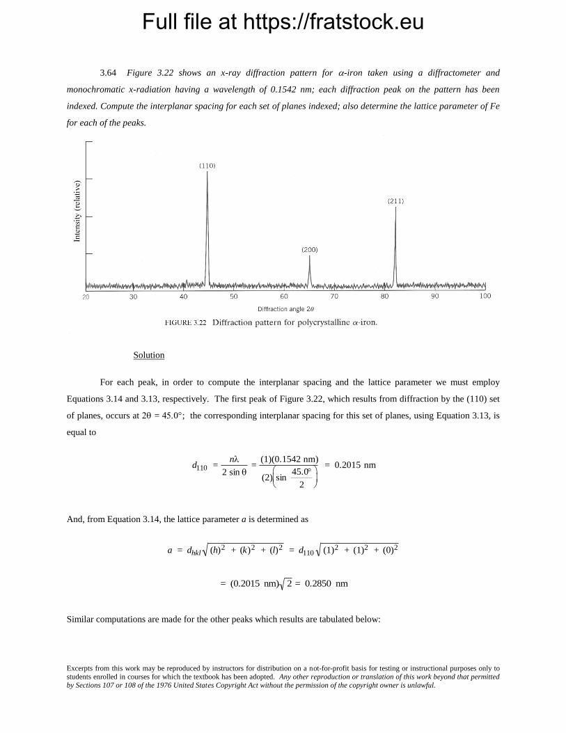
Full file at https://fratstock.eu
Excerpts from this work may be reproduced by instructors for distribution on a not-for-profit basis for testing or instructional purposes only to students enrolled in courses for which the textbook has been adopted. Any other reproduction or translation of this work beyond that permitted by Sections 107 or 108 of the 1976 United States Copyright Act without the permission of the copyright owner is unlawful.
3.64 Figure 3.22 shows an x-ray diffraction pattern for -iron taken using a diffractometer and
monochromatic x-radiation having a wavelength of 0.1542 nm; each diffraction peak on the pattern has been
indexed. Compute the interplanar spacing for each set of planes indexed; also determine the lattice parameter of Fe
for each of the peaks.
Solution
For each peak, in order to compute the interplanar spacing and the lattice parameter we must employ
Equations 3.14 and 3.13, respectively. The first peak of Figure 3.22, which results from diffraction by the (110) set
of planes, occurs at = ; the corresponding interplanar spacing for this set of planes, using Equation 3.13, is
equal to
d110 =n
2 sin =
(1)(0.1542 nm)
(2) sin 45.0
2
= 0.2015 nm
And, from Equation 3.14, the lattice parameter a is determined as
a = dhkl (h)2 + (k)2 + (l)2 = d110 (1)2 + (1)2 + (0)2
= (0.2015 nm) 2 = 0.2850 nm
Similar computations are made for the other peaks which results are tabulated below:

Full file at https://fratstock.eu
Excerpts from this work may be reproduced by instructors for distribution on a not-for-profit basis for testing or instructional purposes only to students enrolled in courses for which the textbook has been adopted. Any other reproduction or translation of this work beyond that permitted by Sections 107 or 108 of the 1976 United States Copyright Act without the permission of the copyright owner is unlawful.
Peak Index 2 dhkl
(nm) a (nm)
200 65.1 0.1433 0.2866
211 82.8 0.1166 0.2856

Full file at https://fratstock.eu
Excerpts from this work may be reproduced by instructors for distribution on a not-for-profit basis for testing or instructional purposes only to students enrolled in courses for which the textbook has been adopted. Any other reproduction or translation of this work beyond that permitted by Sections 107 or 108 of the 1976 United States Copyright Act without the permission of the copyright owner is unlawful.
3.65 The diffraction peaks shown in Figure 3.22 are indexed according to the reflection rules for BCC
(i.e., the sum h + k + l must be even). Cite the h, k, and l indices for the first four diffraction peaks for FCC crystals
consistent with h, k, and l all being either odd or even.
Solution
The first four diffraction peaks that will occur for FCC consistent with h, k, and l all being odd or even are
(111), (200), (220), and (311).

Full file at https://fratstock.eu
Excerpts from this work may be reproduced by instructors for distribution on a not-for-profit basis for testing or instructional purposes only to students enrolled in courses for which the textbook has been adopted. Any other reproduction or translation of this work beyond that permitted by Sections 107 or 108 of the 1976 United States Copyright Act without the permission of the copyright owner is unlawful.
3.66 Figure 3.25 shows the first four peaks of the x-ray diffraction pattern for copper, which has an FCC
crystal structure; monochromatic x-radiation having a wavelength of 0.1542 nm was used.
(a) Index (i.e., give h, k, and l indices) for each of these peaks.
(b) Determine the interplanar spacing for each of the peaks.
(c) For each peak, determine the atomic radius for Cu and compare these with the value presented in Table
3.1.
Solution
(a) Since Cu has an FCC crystal structure, only those peaks for which h, k, and l are all either odd or even
will appear. Therefore, the first peak results by diffraction from (111) planes.
(b) For each peak, in order to calculate the interplanar spacing we must employ Equation 3.13. For the first
peak which occurs at 43.8
d111 =n
2 sin =
(1)(0.1542 nm)
(2) sin43.8
2
= 0.2067 nm
(c) Employment of Equations 3.14 and 3.1 is necessary for the computation of R for Cu as
R =a
2 2=
(dhkl) (h)2 + (k)2 + (l)2
2 2
=(0.2067 nm) (1)2 + (1)2 + (1)2
2 2
= 0.1266 nm
Similar computations are made for the other peaks which results are tabulated below:

Full file at https://fratstock.eu
Excerpts from this work may be reproduced by instructors for distribution on a not-for-profit basis for testing or instructional purposes only to students enrolled in courses for which the textbook has been adopted. Any other reproduction or translation of this work beyond that permitted by Sections 107 or 108 of the 1976 United States Copyright Act without the permission of the copyright owner is unlawful.
Peak Index 2 dhkl
(nm) R (nm)
200 50.8 0.1797 0.1271
220 74.4 0.1275 0.1275
311 90.4 0.1087 0.1274

Full file at https://fratstock.eu
Excerpts from this work may be reproduced by instructors for distribution on a not-for-profit basis for testing or instructional purposes only to students enrolled in courses for which the textbook has been adopted. Any other reproduction or translation of this work beyond that permitted by Sections 107 or 108 of the 1976 United States Copyright Act without the permission of the copyright owner is unlawful.
Noncrystalline Solids
3.67 Would you expect a material in which the atomic bonding is predominantly ionic in nature to be more
or less likely to form a noncrystalline solid upon solidification than a covalent material? Why? (See Section 2.6.)
Solution
A material in which atomic bonding is predominantly ionic in nature is less likely to form a noncrystalline
solid upon solidification than a covalent material because covalent bonds are directional whereas ionic bonds are
nondirectional; it is more difficult for the atoms in a covalent material to assume positions giving rise to an ordered
structure.