the study of impact response of composite …umpir.ump.edu.my/id/eprint/161/1/cd3523.pdf · impak...
TRANSCRIPT

THE STUDY OF IMPACT RESPONSE OF COMPOSITE MATERIAL
MOHD ALFADULY BIN MOHAMAD SALEH
Report submitted in partial fulfillment of the
requirements for the award of the degree of
Bachelor of Mechanical Engineering.
Faculty of Mechanical Engineering
University Malaysia Pahang

ii
NOVEMBER 2008
STUDENT DECLARATION
I declare that this dissertation “The Study of Impact Response of Composite
Material” is the result of my own except as cited in the references. This dissertation
has not been accepted for any degree and is not concurrently submitted in
candidature of any other degree.
Signature :
Name : Mohd Alfadully bin Mohamad Saleh
Date :

iii
To my beloved father and mother
Mr. Mohamad Saleh b Udin
Mdm. Alizah bt Silong

iv
ACKNOWLEDGEMENT
In the praise of Almighty Allah, the Beneficent and Merciful-who showed the
right path of righteousness and blessed me to get the strength to embark upon this
task of peeping into the realms of facts and events.
First of all, I would to thank with heartfelt gratitude to my thesis supervisor,
Dr Thet Thet Mon who has consistently spent her time helping me to create this
valuable work and thank to her moral support that she gave me. Without her guide, I
cannot achieve our target.
I also feel obliged to general, lecturers staff of Faculty of Mechanical
Engineering and my fellow friends especially my co-supervisor Mr. Azmeer Azhari,
Mr. Fahmi and Mr. Hazami, for extending their full cooperation and commitment to
help me in order to finish my research.
Finally, I express my thanks and immeasurable gratitude for every kind of
support that I have from my family, ”Thanks mak and ayah”, to my love “ Thanks
for the support, dear”, friends especially all my classmates from section M17,”I love
you bro”, during my work which otherwise might not have been possible undertaken
by me. Thank you.

v
ABSTRACT
Composite materials have been increasingly used in automotive engineering,
aerospace development, marine technology, electronic devices, and construction
industries. This paper highlights a computational model to analyze the behavior of
composite material subjected to impact load tensile load. General purposed
commercial finite element code was employed to develop the computational model.
Fiber glass reinforced composite, one of the commonly used structural composites,
was chosen for the test material. Computational model was constructed 2-D axis-
symmetric finite elements. Elastic-plastic material model was incorporated into the
finite element modeling to reflect material purpose under impact load and relevant
material properties were taken from the published report. In order to account for high
strain rate effect, load was applied at the nodes of one end while the other end of the
model was constrained. Linear Static Stress was then performed to predict
deformation and damage zone. For comparison purpose, impact tensile test was
carried out the load and the specimen size as close as possible to those used in
computational model. Both computational and experimental results are found to be in
good agreement in terms of damage size.

vi
ABSTRAK
Bahan-bahan komposit semakin banyak digunakan dalam kejuruteraan
automotif, pembangunan angkasa lepas, alat alat elektronik, dan industri pembinaan.
Kertas kerja ini melebihkan kepada model pengkomputeran untuk menganalisi
kelakuan bahan-bahan komposit setelah diasak dengan daya impak.Tujuan utama
kod elemen finit komersial digunakan untuk membangunkan model
pengkomputeran. Komposit diperkukuh dgn serat-kaca adalah bahan yang telah
dipilih untuk menjadi bahan ujikaji. Model pengkomputeran telah dibina dengan
finit elemen 2-D paksi-simetri. Bahan model elastik-plastik telah digandingkan ke
dalam model elemen finit untuk mereflek respon bahan komposit di bawah beban
impak dan ciri-ciri bahan komposit diperoleh dari laporan yang telah diumumkan.
Dalam tujuan untuk mengira efek kadar tarikan tinggi,beban diletakkan pada nod-
nod dan ditetapkan kedudukan pada nod-nod yang bersebelahan. Analisis tekanan
statik selari telah dipertunjukkan untuk menganggar perubahan bentuk dan zon
kerosakan.Untuk tujuan pembezaan, ujian impak tegangan telah dijalanka dengan
beban dan saiz bahan ujian yang mempunyai saiz yang terdekat dengan saiz yang
digunakan model pengkomputeran. Kedua-dua keputusan dari kaedah
pengkomputeran dan eksperimen ditemui di dalam keadaan perjanjian yang baik
dalam terma kawasan dan saiz kerosakan.

vii
TABLES OF CONTENTS
PAGES
STUDENT DECLARATION ii
DEDICATION iii
ACKNOWLEDGEMENT iv
ABSTRACT v
ABSTRAK vi
TABLE OF CONTENT vii
LIST OF TABLES x
LIST OF FIGURES xi
LIST OF SYMBOLS xii
LIST OF APPENDICES xiii
CHAPTER 1 INTRODUCTION
1.1 Project Background 1
1.2 Problem Statement 2
1.3 Objectives of the Project 3
1.4 Scope of the Project 3
1.5 Summary 3
CHAPTER 2 LITERATURE REVIEW
2.1 Introduction 4
2.2 Composite Material 4
2.3 The Methods of Producing Fiber Glass Reinforced 5
2.3.1 Open Molding 5
2.3.2 Vacuum Bag Molding 6
2.3.3 Pressure Bag Molding 6
2.3.4 Autoclave Molding 6
2.3.5 Resin Transfer Molding (RTM) 7
2.4 The Definition of Fiber Glass 8

viii
2.4.1 Properties of Fiber Glass 9
2.5 Glass Reinforced Plastic (GRP) 9
2.6 Application of Fiber Glass 10
2.7 Impact Test 11
2.7.1 Charpy Impact Test 12
2.7.2 Izod Impact Strength Test 13
2.7.3 Impact Tensile Test 13
2.7.4 Quantitative Result 14
2.7.5 Qualitative Result 15
2.8 Impact Loading 15
2.9 Finite Element Analysis 16
2.9.1 Application of Finite Element Analysis 17
2.9.2 Tsai-Wu Criterion 17
2.9.3 Applications of FEA to the Mechanical Engineering 18
Industry
2.9.4 Computer-aided Design and Finite Element Analysis 19
in Industry
2.9.5 Current FEA trends in industry 21
2.9.5.1 Dynamic modeling 21
2.9.5.2 Modeling Assemblies 21
2.9.5.3 Current Modeling Techniques in Industry 22
2.9.6 Review on Previous Impact Test of Glass 23
Fiber Reinforced Polymer
CHAPTER 3 METHODOLOGY
3.1 Introduction 24
3.2 Flow Chart 25
3.3 Impact Tensile Test 26
3.4 Specimen Preparation 27
3.4.1 The Specimen Dimension 28
3.4.2 Experimental Set-Up 28
3.5 Impact Analysis with CAE Software 29

ix
3.5.1 ALGOR V16 Fempro 29
3.6 Finite Element Model 29
3.6.1 Model Geometry 29
3.6.2 Mesh Optimization 30
3.6.3 Composite Laminate Stacking Sequence 31
3.6.4 Model Validation 32
3.6.5 Simulation with Various Impact Load 32
3.7 Chapter Summary 32
CHAPTER 4 RESULT AND DISCUSSION
4.1 Introduction 33
4.2 Impact Tensile Test Experiment 33
4.3 Finite Element Model 34
4.4 Mesh Optimization 34
4.5 Calculation of Equivalent Static Load under 36
Impact Energy
4.6 Finite Element Result s 38
4.7 Model Validation 41
4.8 Simulation with Various Impact Tensile Loads 42
4.9 Summary 46
CHAPTER 5 CONCLUSION AND RECOMMENDATIONS
5.1 Conclusion 47
5.2 Recommendations 48
REFERENCES 49-51
APPENDICES 53-54

x
LIST OF TABLES
TABLE NO. TITLE PAGE
3.1 Fiber Glass Orientation 31
3.2 Material Properties 31
3.3 Tsai-Wu Parameter 32
4.1 Experimental Result for 7.5 J 33
4.2 Mesh Optimization Table 35
4.3 Equivalent Static Load Due to Impact 37
Tensile Energy

xi
LIST OF FIGURES
FIGURE NO. TITLE PAGE
2.1 Glass Fiber Reinforced Polymer 4
2.2 Continuous Fiber Glass 8
2.3 The Charpy Impact Test Machine 12
2.4 The Impact Tensile Test 14
3.1 Flow Chart 25
3.2 The Zwick Roell Impact Pendulum Tester 26
3.3 Composite Specimen 27
3.4 Specimen Dimension in millimeter (mm) 28
3.5 Specimen Set-Up 28
3.6 Model Geometry 29
3.7 Model Mesh 30
4.1 Finite Element Model 34
4.2 Mesh Optimization 35
4.3 Predicted Displacement for Impact Energy 38
7.5J
4.4 Predicted Stress for Impact Energy 7.5J 39
4.5 Predicted Failure Index for Impact 40
Energy 7.5J
4.6 Displacement (mm) versus Impact 42
Energy (J)
4.7 Stress (Mpa) versus Strain (mm/mm) 43
4.8 Stress (Mpa) versus Impact Energy (J) 44
4.9 Stress (Mpa) versus Failure Index 45

xii
LIST OF SYMBOLS AND ABBREVIATIONS
SYMBOLS
A Area (in m2)
ASTM American Society of Testing and Materials
CSM Chopped Strand Mat
DBTT Ductile-Brittle Transition Temperature
E Modulus of Elasticity (in Pa)
FE Finite Element
FEA Finite Element Analysis
FEM Finite Element Method
FRP Fiber Reinforced Polymer
GRE Glass Reinforced Epoxy
GRP Glass Reinforced Polymer
IGES Save format in Solidwork Software
L Length (in meter)
m Mass (in kg)
PDE Partial Differential Equation
Pm Equivalent Static Load (in N)
RTM Resin Transfer Molding
T Kinetic Energy
U Strain Energy
v0 Velocity (in m/s)
σm Stress (in Pa)

xiii
LIST OF APPENDICES
APPENDIX TITLE PAGE
A Sample of Calculation of Equivalent Static Load 52
B Gantt chart For Final Year Project I 53
Gantt chart For Final Year Project II 54

CHAPTER 1
INTRODUCTION
1.1 PROJECT BACKGROUND
Composite materials (or composites for short) can be defined as engineered
materials made from two or more constituent materials which contain significantly
different physical or chemical properties and remain separate and distinct on a
macroscopic level within the finished structure. There are two types of composite,
the first one is short fiber reinforced polymer and the other one is continuous fiber
reinforced polymer [2].
Glass fiber reinforced polymer or plastic is one of the example of composite
material. Fiberglass is material made from extremely fine fibers of glass. The role of
these fibers is as a reinforcement agent for polymer products. Fiber glass is widely
used in electronic, marine and automotive industries [2].
With the increased application of glass fibre composite in dynamic situation ,
knowledge of impact strength of this material is becoming important. As such,
considerable amount of research has devoted to study the strength of this composite
under dynamic load using computational and experimental methods [1].
Among the computational method, finite element method (FEM) is a widely-
used method due to its flexibility to model and analyze variety of engineering
problems[4]. Some popular FE packages p to date are Algor Software, ANSYS,
Dyna and many more.

2
Major advantage of FEM is we can reduce the cost of experimenting. Impact
analysis is expensive whereas the material will be analyzed and it will be failed
intentionally [3]. Another than that, the analysis is a time consuming process, by
using FEA method we can save a lot of valuable time and reduced losses.
Based on the information and published journal found, the number of journal
that related to the impact test of fiber glass is still low. The journals found are mostly
research on other composite materials such as carbon fiber and so on. With this
impact response test, it will give other researchers the new information on fiber glass
characteristic.
1.2 PROBLEM STATEMENTS
Firstly, the study about fiber glass composite is one of enormous complexity.
A single impact event can produce several different damage modes simultaneously.
In glass fiber material the damages can hardly detect, so, it is important to identify
the factor that contributes to the damages [5]. It would be very dangerous in some
application such as automobiles and so on. Because of all these factors, impact
response test will be carried out.
In addition, the other problem is to researchers cannot model easily the
fiberglass in the FEA software [6, 7]. The value of the mechanical properties need to
known unless the simulation cannot be done. It is important to get the correct result.

3
1.3 OBJECTIVES OF THE PROJECT
The project objectives are:
i. To develop computational model of response of fiber-glass composite under
impact load using finite element method.
ii. To verify the computational model with impact experiment.
iii. To analyze the behavior of fiber-glass composite under various impact load
using the above computational model.
1.4 SCOPE OF THE PROJECT
The scopes of this project are:
i. Analysis of fiber glass reinforced polymer subjected to impact using Finite
element method (FEM) will be studied.
ii. Experimental result will be obtained from impact test in laboratory.
iii. FEM will be validated by experiment.
iv. Algor finite element code will be used to analyze the impact test virtually.
1.5 SUMMARY
This chapter is generally about background, problem statement, objectives of
the project and scope of the project in order to achieve the objectives as
mentioned.

CHAPTER 2
LITERATURE REVIEW
2.1 INTRODUCTION
The main purpose if this literature review is to get information about the
project reference books, magazines, journals, technical papers and web sites. In this
chapter, the information gathered from a variety of sources will be discussed.
2.2 COMPOSITE MATERIAL
Composite materials or composites for short are engineered materials made
from two or more constituent materials as shown in Figure 2.1. Each one of them has
significantly different physical or chemical properties. The combination of the
materials can remain separate and distinct on a macroscopic level within the finished
structure. These materials are widely used in automotive industries, boat making
industries and so on [6].
Figure 2.1: Glass Fiber Reinforced Polymer

5
2.3 THE METHOD OF PRODUCING FIBER GLASS REINFORCED
POLYMER
Generally, the reinforcing and matrix materials are combined, compacted and
processed to undergo a melding or a blending event. After the melding event, the part
shape is essentially set, although it can deform under certain process conditions.
For a thermo set polymeric matrix material, the melding event is a curing
reaction that is initiated by the application of additional heat or chemical reactivity
such as organic peroxide. For a thermoplastic polymeric matrix material, the melding
event is solidification from the melted state. For a metal matrix material such as
titanium foil, the melding event is a fusing at high pressure and a temperature near
the melt point. In process of producing fiber glass reinforced polymer, there is
several most popular method used in the industries [8].
2.3.1 Open Molding
Open molding is a process using a rigid, one sided which shapes only one
surface of the panel. While the opposite surface is determined by the amount of
material placed upon the lower mold. Reinforcement materials can be placed
manually by human or robotically. For the examples of reinforcement agent are
continuous fiber forms fashioned into textile constructions and chopped fiber. The
matrix is generally a resin, and can be applied with a pressure roller, a spray device
or manually. This process is generally done at ambient temperature and atmospheric
pressure. Two variations of open molding are Hand Lay-up and Spray-up[8].

6
2.3.2 Vacuum Bag Molding
This process using a two-sided mold set that shapes both surfaces of the
panel. On the lower side is a rigid mold and on the upper side is a flexible membrane
or vacuum bag. The flexible membrane can be a reusable silicone material or an
extruded polymer film [7]. Then, vacuum is applied to the mold cavity. This process
can be performed at either ambient or elevated temperature with ambient
atmospheric pressure acting upon the vacuum bag. Most economical way is using a
venturi vacuum and air compressor or a vacuum pump.
2.3.3 Pressure Bag Molding
This process is related to vacuum bag molding in exactly the same way as it
sounds. A solid female mold is used along with a flexible male mold. The
reinforcement is place inside the female mold with just enough resin to allow the
fabric to stick in place. A measured amount of resin is then liberally brushed
indiscriminately into the mold and the mold is then clamped to a machine that
contains the male flexible mold [8].
The flexible male membrane is then inflated with heated compressed air or
possibly steam. The female mold can also be heated. Excess resin is forced out along
with trapped air. Cycle times for a helmet bag molding machine vary from 20 to 45
minutes, but the finished shells require no further curing if the molds are heated.
2.3.4 Autoclave Molding
A process using a two-sided mold set that forms both surfaces of the panel.
On the lower side is a rigid mold and on the upper side is a flexible membrane made
from silicone or an extruded polymer film such as nylon. Reinforcement materials
can be placed manually or robotically. They include continuous fiber forms

7
fashioned into textile constructions. Most often, they are pre-impregnated with the
resin in the form of prepreg fabrics or unidirectional tapes. In some instances, a resin
film is placed upon the lower mold and dry reinforcement is placed above. The upper
mold is installed and vacuum is applied to the mold cavity. The assembly is placed
into an autoclave pressure vessel. This process is generally performed at both
elevated pressure and elevated temperature. The use of elevated pressure facilitates a
high fiber volume fraction and low void content for maximum structural efficiency.
2.3.5 Resin transfer molding (RTM)
A process using a two-sided mold set that forms both surfaces of the panel.
The lower side is a rigid mold. The upper side can be a rigid or flexible mold.
Flexible molds can be made from composite materials, silicone or extruded polymer
films such as nylon. The two sides fit together to produce a mold cavity. The
distinguishing feature of resin transfer molding is that the reinforcement materials are
placed into this cavity and the mold set is closed prior to the introduction of matrix
material.
Resin transfer molding includes numerous varieties which differ in the
mechanics of how the resin is introduced to the reinforcement in the mold cavity.
These variations include everything from vacuum infusion (see also resin infusion) to
vacuum assisted resin transfer molding. This process can be performed at either
ambient or elevated temperature.
8
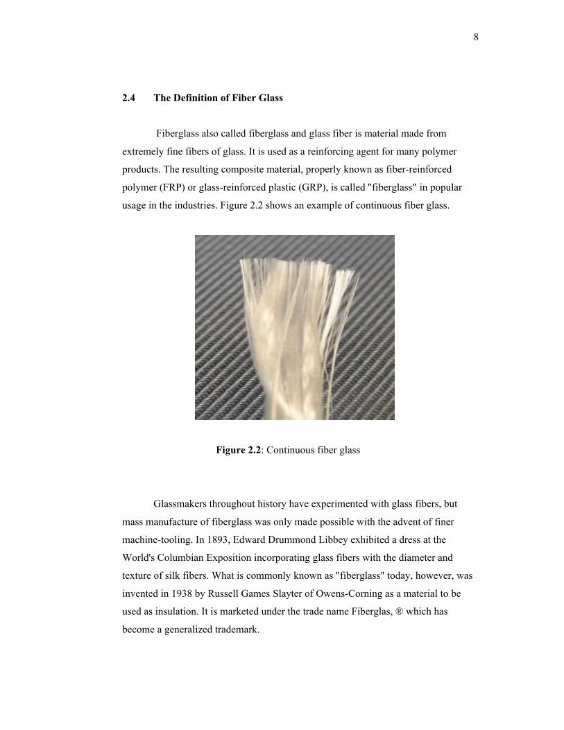
2.4 The Definition of Fiber Glass
Fiberglass also called fiberglass and glass fiber is material made from
extremely fine fibers of glass. It is used as a reinforcing agent for many polymer
products. The resulting composite material, properly known as fiber-reinforced
polymer (FRP) or glass-reinforced plastic (GRP), is called "fiberglass" in popular
usage in the industries. Figure 2.2 shows an example of continuous fiber glass.
Figure 2.2: Continuous fiber glass
Glassmakers throughout history have experimented with glass fibers, but
mass manufacture of fiberglass was only made possible with the advent of finer
machine-tooling. In 1893, Edward Drummond Libbey exhibited a dress at the
World's Columbian Exposition incorporating glass fibers with the diameter and
texture of silk fibers. What is commonly known as "fiberglass" today, however, was
invented in 1938 by Russell Games Slayter of Owens-Corning as a material to be
used as insulation. It is marketed under the trade name Fiberglas, ® which has
become a generalized trademark.

9
2.4.1 Properties of Fiber Glass
Glass fibers are useful because of their high ratio of surface area to weight [1]
However, the increased surface area makes them much more susceptible to chemical
attack. By trapping air within them, blocks of glass fiber make good thermal
insulation, with a thermal conductivity of 0.05 W/m-K.
Glass strengths are usually tested and reported for "virgin" fibers: those
which have just been manufactured. The freshest, thinnest fibers are the strongest
because the thinner fibers are more ductile. The more the surface is scratched, the
less the resulting tenacity.[3] Because glass has an amorphous structure, its
properties are the same along the fiber and across the fiber.[2] Humidity is an
important factor in the tensile strength. Moisture is easily adsorbed, and can worsen
microscopic cracks and surface defects, and lessen tenacity.
In contrast to carbon fiber, glass can undergo more elongation before it
breaks.[2] The viscosity of the molten glass is very important for manufacturing
success. During drawing (pulling of the glass to reduce fiber circumference) the
viscosity should be relatively low. If it is too high the fiber will break during
drawing, however if it is too low the glass will form droplets rather than drawing out
into fiber.
2.5 GLASS REINFORCED PLASTIC (GRP)
Glass-reinforced plastic (GRP) is a composite material or fiber-reinforced
plastic made of a plastic reinforced by fine fibers made of glass. For the example of
graphite-reinforced plastic, the composite material is commonly referred to by the
name of its reinforcing fibers (fiberglass). The plastic is thermosetting, most often
polyester or vinylester, but other plastics, like epoxy (GRE), are also used. The glass
is mostly in the form of chopped strand mat (CSM), but woven fabrics are also used.

10
As with many other composite materials (such as reinforced concrete), the
two materials act together, each overcoming the deficits of the other. Whereas the
plastic resins are strong in compressive loading and relatively weak in tensile
strength, the glass fibers are very strong in tension but have no strength against
compression. By combining the two materials together, GRP becomes a material that
resists well both compressive and tensile forces. The two materials may be used
uniformly or the glass may be specifically placed in those portions of the structure
that will experience tensile loads.
2.6 APPLICATIONS OF GLASS POLYMER
GRP was developed in the UK during the Second World War as a
replacement for the molded plywood used in aircraft radomes (GRP being
transparent to microwaves). Its first main civilian application was for building of
boats, where it gained acceptance in the 1950s. Its use has broadened to the
automotive and sport equipment sectors, although its use there is being taken over by
carbon fiber which weighs less per given volume and is stronger both by volume and
by weight. GRP uses also include hot tubs, pipes for drinking water and sewers.
Advanced manufacturing techniques such as pre-pregs and fiber rovings
extend the applications and the tensile strength possible with fiber-reinforced
plastics.
GRP is also used in the telecommunications industry for shrouding the visual
appearance of antennas, due to its RF permeability and low signal attenuation
properties. It may also be used to shroud the visual appearance of other equipment
where no signal permeability is required, such as equipment cabinets and steel
support structures, due to the ease with which it can be molded, manufactured and
painted to custom designs, to blend in with existing structures or brickwork. Other
uses include sheet form made electrical insulators and other structural components
commonly found in the power industries.

11
Glass reinforced plastics are also used in the house building market for the
production of roofing laminate, door surrounds, over-door canopies, window
canopies & dormers, chimneys, coping systems, heads with keystones and cills. The
use of GRP for these applications provides for a much faster installation and due to
the reduced weight manual handling issues are reduced. With the advent of high
volume manufacturing processes it is possible to construct GRP brick effect panels
which can be used in the construction of composite housing.
These panels can be constructed with the appropriate insulation which
reduces heat loss. The fiber glasses are also widely used in piping such as
underground as well as above. For example, the firewater systems, cooling water
systems, drinking water systems and waste water systems or sewage systems.
2.7 IMPACT TESTS
Impact Analysis is a technique that helps researchers to think through the full
impacts of a proposed change. As such, it is an essential part of the evaluation
process for major decisions. It is very reliable to predict the damages that could occur
[5].
Furthermore, it gives the ability to spot problems before, so that companies
can develop contingency plans to avoid these issues smoothly. This can help the
researchers to make the difference between well-controlled and seemingly-effortless
project management. However there are of types for impact test.