the study of the mechanical properties and structure of ... · ductile iron, which was ... the...
TRANSCRIPT

A R C H I V E S
o f
F O U N D R Y E N G I N E E R I N G
Published quarterly as the organ of the Foundry Commission of the Polish Academy of Sciences
ISSN (1897-3310) Volume 7
Issue 1/2007 161 – 166
35/1
Mechanical properties and structure of
austempered ductile iron -ADI
M. Kaczorowski a), A. Krzyńska b)
a) Institute of Mechanics and Design b) Institute of Materials Processing
Faculty of Production Engineering, Warsaw University of Technology, ul. Narbutta 85, 02-524 Warszawa, POLAND
Summary The results of experimental study of austempered ductile iron are presented. The aim of the investigations was to look closer into the structure – mechanical properties relationships of this very attractive cast material. The experiment was carried out with 500 7 grade ductile iron, which was austempered using different parameters of heat treatment. The specimens were first solution treated 1 hour in 910oC and then isothermally quenched for different time in silicon oil bath of temperature 275, 325, 300 and 350oC. The mechanical properties heat treated specimens were tested in tensile to evaluate yield stress R e, 0.2, tensile strength Rm and elongation A10. Additionally hardness of heat treated samples was measured using Brinell-Rockwell hardness tester. Structure of the specimens was studied either with conventional metallography, scanning (SEM) and transmission (TEM) electron microscopy. It followed from the study that conventional grade ductile iron enabled to produce both low and high strength ADI, depend on heat treatment parameters. As expected the low temperature isothermal quenching produced higher strength ADI compare to the same ductile iron but austempered at 350oC. It was discovered however, that low yield strength ADI obtained for short time quenching at 275oC exhibited high strengthening effect while strained in tensile. So it was concluded that this had to by cause by large amount of untransformed austenite, which FCC lattice is characterized by high strengthening coefficient. Key words: ADI; Heat Treatment Parameters; Structure; Properties.
1. Introduction
Austemperd ductile iron – ADI [1] looks to be probably the most outstanding achievement in the metallurgy of cast iron. The relative simple heat treatment, low cost and very interesting combination strength and ductility make it very attractive material for many applications. The ADI technology involve the solution heat treatment at the temperature 850-950oC which is followed by isothermal quenching in the temperature range 250 – 400oC. Depends on the heat treatment parameters, high strength ADI with Rm=1600MPa or mediate strength ADI with Rm= 800MPa but 10% elongation can be obtained [2]. These mechanical properties results from specific metal matrix microstructure of ADI, which is the mixture of carbon stabilized austenite and bainitic ferrite cold ausferrite. The ductility of austempered ductile iron depends
mostly on relative amount of austenite with FCC lattice which relative amount in case of high temperature austempering may reach 40% or even more. On the other hand the high strength, low ductile ADI is obtained in case of low temperature isothermal quenching. In this case, except carbon stabilized austenite and bainitic ferrite some amount of martensite forms. The relative proportion between each component in ADI microstructure depends not only on the temperature but also time of austempering. This relationship was summarized in form of graphs one of which was showed in fig.1 [3]. Attractive mechanical properties, low cost and no special requirements concerning chemical composition make ADI competitive not only to conventional ductile iron but also with cast steel and in some cases even aluminum alloys [4].
A R C H I V E S o f F O U N D R Y E N G I N E E R I N G V o l u m e 7 , I s s u e 1 / 2 0 0 7 , 1 6 1 - 1 6 6
161

Fig. 1. The microstructure of ADI as function of austempering time at temperature T = 300 - 350oC [3]
These are the reasons why ADI is the subject of interest
many researchers also in Poland [5-9]. Although, many publications appeared since ADI was discovered, it will probably take a long time before it would by understand as good as other cast materials. On of the reason is that regular ductile iron which is starting material before austempering, very often is non-homogenous material from point of view its chemistry. For example silicon segregates close to graphite nodules, while manganese shows opposite segregation. The non uniform chemical composition influences the process of decomposition of super-cooled austenite, it mean start and course of austempering process.
According to Taran and coworkers [10], the process of decomposition of super-cooled austenite during isothermal quenching can be described as follows: a Stage 1: γ(Cγo) → α + γC(γsupersaturated) b Stage 2: Stability of two phase (α + γC(γsupersaturated)) structure c Stage 3: γC(γsupersaturated) → α + (ε or Fe3C) carbides
In the first stage of reaction the super-cooled austenite of equilibrium carbon concentration - γ(Cγo) will decompose into low carbon bainitc ferrite - α and enriched with carbon austenite – γC (γsupersaturated). The high carbon concentration in austenite wills it stabilize, so this carbon stabilized austenite together with bainitic ferrite form microstructure – ausferrite, which is stable for some time called “processing window”. This time region is typically used for producing ADI because it enables to produce ADI of the best combination strength and ductility. The third
stage is accompanied with carbide formation which decreases strongly the plastic properties of ADI.
However there is no special demands concerning ADI, except the good quality ductile iron, the decomposition of super-cooled austenite proceeding at three stages described above depend strongly on this chemical composition, and especially segregation of alloying elements. It is known, that silicon segregate mainly close to the graphite nodule while manganese at eutectic cell boundaries [11]. This in turn will influence the offset and speed of austenite decomposition into ausferrite and further into bainitic ferrite and carbides.
The aim of this study is to find out how the time of isothermal quenching influences the mechanical properties and structure of ductile iron.
2. Experimental procedure
The commercial EN-GJS-500-7 grade ductile iron was selected for the study. The metal was melted in three ton induction furnace. The spheroidizing treatment was carried out with FeSiMg alloy using covered ladle method. Molten metal was inoculated with FeSi75 alloy and then poured into green sand moulds. The castings were 30mm diameter and 230mm length rods. From these castings 4mm diameter mini-samples for tensile were cut. The samples were solution heat treated 1h at 900oC and then austempered at temperature 275, 300, 325 and 350oC. The austempering time equaled: 15, 45 and 90 minutes for all austempering temperatures and additionally 30 and 180 minutes for austempering at the temperatures 275 and 300oC. The test specimens were numbered with code use temperature and time parameters, e.g. 275-45 – denote ADI specimen austempered 45 min. at T 275oC. After final heat treatment the specimens were grinded to remove surface layer thickness of 0.2mm, which could be decarburized while solid solution heat treated. The specimen were tensile tested using Instron 1115 to evaluate yield strength –Re,0.2, tensile strength - Rm and elongation - A10. For each heat treatment parameter three specimens were used. Except tensile test, Brinnel hardness measurements were carried out. In this case 2.5mm steel ball loaded 15s with force F = 187.5N was used.
For microstructure investigations light microscopy, scanning electron microscopy (SEM) and transmission electron microscopy (TEM) were employed. Microstructure observations were carried out on metallographic specimens prepared using conventional grinding and polishing. For etching 4%HNO3 solution in C2H5OH was used. The microstructure was observed in Olympus IX-70 light microscope using different magnifications and mode of observations. The SEM investigations were performed in Hitachi scanning electron microscope working at U = 20kV, using secondary electrons (SE). TEM studies were carried out using thin foil technique. The preparation of thin foils included cutting 3mm diameter rods from the casting. From these rods 0.1mm thick discs were sliced with load less wire saw IF-07A. These preliminary slices were then very carefully grinded, dimpled and finally ion milled using Gatan equipment. Thin foil were observed in Philips EM 300 microscope operating at 100kV equipped with goniometer for specimen tilting in the range ±45 deg.
A R C H I V E S o f F O U N D R Y E N G I N E E R I N G V o l u m e 7 , I s s u e 1 / 2 0 0 7 , 1 6 1 - 1 6 6
162

3. Results 3.1. Mechanical testing
The results of mechanical testing were given in form of graphs (fig.2). As it could be expected the lower time of austempering the higher strength properties of ADI test casting.
The increase of ductility while austempered in 350oC may result from higher amount of stabilized with carbon austenite.
In next graph (fig.3) the changes of elongation with austempering time and temperature are given. It follows from the experimental date, that, except austempering at 350oC (dark points), ductility of ADI test casting decrease with austempering
time increase. In case of short austempering time only part of austenite has been enriched with carbon and the rest will transform into brittle martensite. These results are not surprising, because the lower austempering time the lower ductility which is very well known as a property opposite to strength.
In fig.4 the results of hardness measurements in function time and austempering temperature were depicted. As could be expected the lower temperature of austempering the higher hardness of ADI test specimens. So it is no surprising that hardness measurements reflecting the strength properties of material confirm the results presented in fig.2.
a)
0
200
400
600
800
1000
1200
1400
1600
0 30 60 90 120 150 180Time [min]
Re,
0.2 &
Rm
[MP
a]
Rp,0.2Rm
b)
0
200
400
600
800
1000
1200
1400
0 30 60 90 120 150 180
Time [min]
Re,
0.2 &
Rm [M
Pa]
Re,0.2Rm
c)
0
200
400
600
800
1000
1200
0 30 60 90 120Time [min]
Re,
0.2 &
Rm [M
Pa]
Re,0.2Rm
d)
0
200
400
600
800
1000
1200
0 30 60 90Time [min]
Re,
0.2 &
Rm [M
Pa]
120
Re,0.2Rm
Fig.2. The values of yield – Re,0.2 and tensile strength – Rm as function of austempering time at the temperature: a – 275oC, b – 300oC, c –325oC and d – 350oC
A R C H I V E S o f F O U N D R Y E N G I N E E R I N G V o l u m e 7 , I s s u e 1 / 2 0 0 7 , 1 6 1 - 1 6 6
163
0,0
0,5
1,0
1,5
2,0
2,5
3,0
3,5
4,0
0 15 30 45 60 75 90 105 120 135 150 165 180 195
Austempering time [min]
Elo
ngat
ion
A 10
[&%
]
275 deg300 deg325 deg350 deg
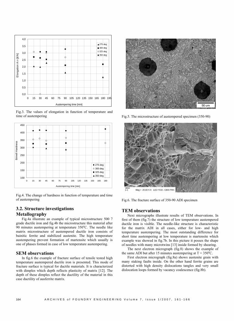
Fig.3. The values of elongation in function of temperature and time of austempering
100
150
200
250
300
350
400
450
0 15 30 45 60 75 90 105 120 135 150 165 180
Austempering time [min]
Brin
ell H
ardn
ess
275 deg300 deg325 deg350 deg
Fig.4. The change of hardness in function of temperature and time of austempering
3.2. Structure investigations Metallography
Fig.4a illustrate an example of typical microstructure 500 7 grade ductile iron and fig.4b the microstructure this material after 90 minutes austempering at temperature 350oC. The needle like matrix microstructure of austempered ductile iron consists of bainitic ferrite and stabilized austenite. The high temperature austempering prevent formation of martensite which usually is one of phases formed in case of low temperature austempering. SEM observations
In fig.6 the example of fracture surface of tensile tested high temperature austempered ductile iron is presented. This mode of fracture surface is typical for ductile materials. It is characterized with dimples which depth reflects plasticity of matrix [12]. The depth of these dimples reflect the ductility of the material in this case ductility of ausferrite matrix.
Fig.5. The microstructure of austempered specimen (350-90)
Fig.6. The fracture surface of 350-90 ADI specimen TEM observations Next micrographs illustrate results of TEM observations. In first of them (fig.7) the structure of low temperature austempered ductile iron is visible. The needle-like structure is characteristic for the matrix ADI in all cases, either for low- and high temperature austempering. The most outstanding difference for short time austempering at low temperature is martensite which example was showed in fig.7b. In this picture it posses the shape of needles with many microtwins [13] inside formed by shearing.
The next electron micrograph (fig.8) shows the example of the same ADI but after 15 minutes austempering at T = 350oC.
First electron micrograph (fig.8a) shows austenite grain with many staking faults inside. On the other hand ferrite grains are distorted with high density dislocations tangles and very small dislocation loops formed by vacancy coalescence (fig.8b).
A R C H I V E S o f F O U N D R Y E N G I N E E R I N G V o l u m e 7 , I s s u e 1 / 2 0 0 7 , 1 6 1 - 1 6 6
164

a.
b.
Fig.7. The microstructure: a – needaustempered ductile iron (x 18.000), b ADI observed at very high magnification
The next set of electron microgstructure of ADI specimen austempered the upper right corner of first SAD patte
The careful analysis of SAD discospots located close to the central 000 difcorrespond to the carbides which must bplates. This conclusion based on the shshows so called ‘streaks” [14]. As fol[15] micrograph obtained with the usetiny reflexes, the carbides are locaboundaries (see white rows of the carbid
4. Discussion Since there is no space enough for dwith very short analysis the results of mall is worth noting the specific behavioris different in value for different austepractically did not change a lot at the tThe similar behavior, although not so cstress, except that for austempering at
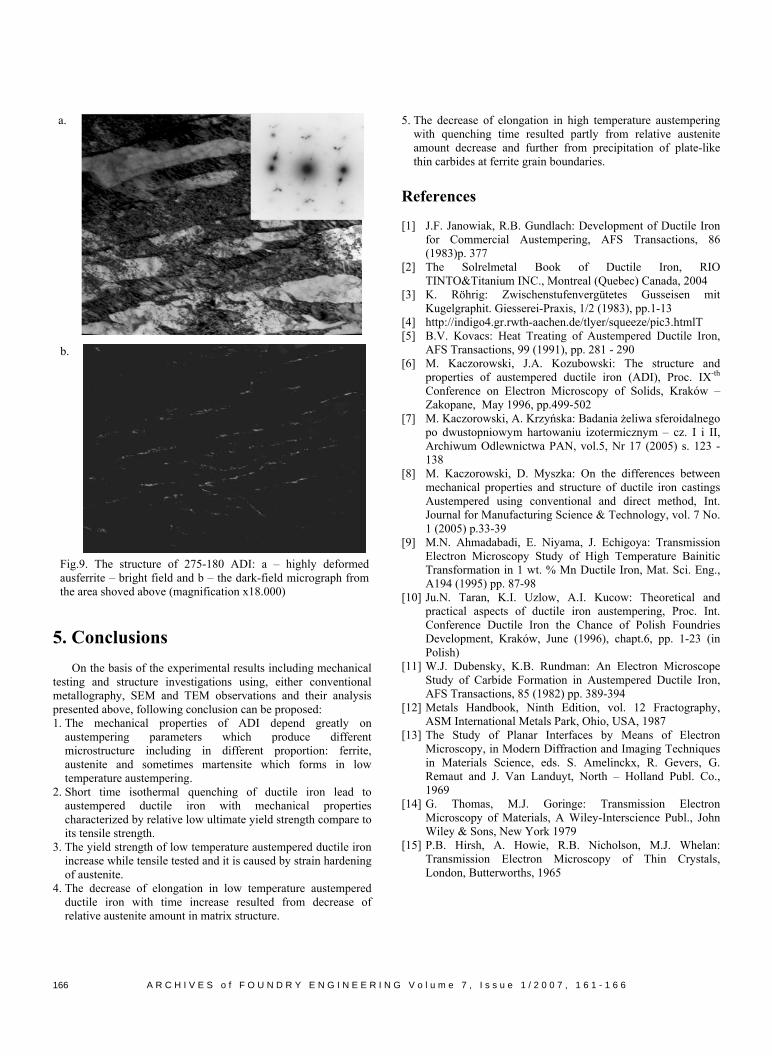
clear increase of Re,0.2 is observed. This cause that for 15 minutes austempering the difference ∆R = Rm – Re,0.2 ≈ 700MPa, while after 180 minutes austempering this difference equals less than 170MPa (fig.2a). In case of short time austempering strong strain hardening is observed. The phases which can exist in the structure are: bainitic ferrite, carbon stabilized austenite and some martensite. Knowing the crystal lattice and properties of these phases it is easy to conclude that only austenite with FCC lattice might be responsible for strain hardening. This conclusion is partly confirmed by changes of elongation with time (fig.3). In this picture it is clear visible that the highest elongation of ADI specimen’s austempered at 275oC is observed for short time heat treatment. As documented in fig.6b, except ausferrite, some amount of martensite forms. The long needles of martensite are highly distorted with enormous number very fine microtwins, the thickness of 10nm.
a.
A R C H I V E S o f F
↓ Martensite
le-like structure 275-15 – martensite in the same (x 90.000)
raphs (fig.9) shows the 180 minutes at 275oC. In rn was located (fig.7a). vers very tiny diffraction fraction spot. These spots e in shape of relative thin ape of the reflexes which lows from the dark-field just one of those diffuse ted at the ferrite grain es in fig.9b).
etailed discussion we start echanical testing. First of of tensile strength which mpering temperature but ime region up to 90 min. lear is observed for yield 275oC. In this case very
b.
Fig.8. The structure of 350-15 ADI: a – austenite with stacking faults, b – austenite and bainitic ferrite (the last with many dislocations and dislocation loops)
The 180 minutes austempering leads to decomposition of carbon stabilized austenite from which thin plate-like carbides precipitates. These are located at grain boundaries (fig.9b) which are most preferred sites for nucleation and growth.
O U N D R Y E N G I N E E R I N G V o l u m e 7 , I s s u e 1 / 2 0 0 7 , 1 6 1 - 1 6 6 165
a.
b.
Fig.9. The structure of 275-180 ADI: a – highly deformed ausferrite – bright field and b – the dark-field micrograph from the area shoved above (magnification x18.000)
5. Conclusions
On the basis of the experimental results including mechanical testing and structure investigations using, either conventional metallography, SEM and TEM observations and their analysis presented above, following conclusion can be proposed: 1. The mechanical properties of ADI depend greatly on
austempering parameters which produce different microstructure including in different proportion: ferrite, austenite and sometimes martensite which forms in low temperature austempering.
2. Short time isothermal quenching of ductile iron lead to austempered ductile iron with mechanical properties characterized by relative low ultimate yield strength compare to its tensile strength.
3. The yield strength of low temperature austempered ductile iron increase while tensile tested and it is caused by strain hardening of austenite.
4. The decrease of elongation in low temperature austempered ductile iron with time increase resulted from decrease of relative austenite amount in matrix structure.
5. The decrease of elongation in high temperature austempering with quenching time resulted partly from relative austenite amount decrease and further from precipitation of plate-like thin carbides at ferrite grain boundaries.
References
[1] J.F. Janowiak, R.B. Gundlach: Development of Ductile Iron
for Commercial Austempering, AFS Transactions, 86 (1983)p. 377
[2] The Solrelmetal Book of Ductile Iron, RIO TINTO&Titanium INC., Montreal (Quebec) Canada, 2004
[3] K. Röhrig: Zwischenstufenvergütetes Gusseisen mit Kugelgraphit. Giesserei-Praxis, 1/2 (1983), pp.1-13
[4] http://indigo4.gr.rwth-aachen.de/tlyer/squeeze/pic3.htmlT [5] B.V. Kovacs: Heat Treating of Austempered Ductile Iron,
AFS Transactions, 99 (1991), pp. 281 - 290 [6] M. Kaczorowski, J.A. Kozubowski: The structure and
properties of austempered ductile iron (ADI), Proc. IX-th Conference on Electron Microscopy of Solids, Kraków – Zakopane, May 1996, pp.499-502
[7] M. Kaczorowski, A. Krzyńska: Badania żeliwa sferoidalnego po dwustopniowym hartowaniu izotermicznym – cz. I i II, Archiwum Odlewnictwa PAN, vol.5, Nr 17 (2005) s. 123 -138
[8] M. Kaczorowski, D. Myszka: On the differences between mechanical properties and structure of ductile iron castings Austempered using conventional and direct method, Int. Journal for Manufacturing Science & Technology, vol. 7 No. 1 (2005) p.33-39
[9] M.N. Ahmadabadi, E. Niyama, J. Echigoya: Transmission Electron Microscopy Study of High Temperature Bainitic Transformation in 1 wt. % Mn Ductile Iron, Mat. Sci. Eng., A194 (1995) pp. 87-98
[10] Ju.N. Taran, K.I. Uzlow, A.I. Kucow: Theoretical and practical aspects of ductile iron austempering, Proc. Int. Conference Ductile Iron the Chance of Polish Foundries Development, Kraków, June (1996), chapt.6, pp. 1-23 (in Polish)
[11] W.J. Dubensky, K.B. Rundman: An Electron Microscope Study of Carbide Formation in Austempered Ductile Iron, AFS Transactions, 85 (1982) pp. 389-394
[12] Metals Handbook, Ninth Edition, vol. 12 Fractography, ASM International Metals Park, Ohio, USA, 1987
[13] The Study of Planar Interfaces by Means of Electron Microscopy, in Modern Diffraction and Imaging Techniques in Materials Science, eds. S. Amelinckx, R. Gevers, G. Remaut and J. Van Landuyt, North – Holland Publ. Co., 1969
[14] G. Thomas, M.J. Goringe: Transmission Electron Microscopy of Materials, A Wiley-Interscience Publ., John Wiley & Sons, New York 1979
[15] P.B. Hirsh, A. Howie, R.B. Nicholson, M.J. Whelan: Transmission Electron Microscopy of Thin Crystals, London, Butterworths, 1965
A R C H I V E S o f F O U N D R Y E N G I N E E R I N G V o l u m e 7 , I s s u e 1 / 2 0 0 7 , 1 6 1 - 1 6 6
166