the study of the voltage fluctuation of on-load capacity
TRANSCRIPT

The Study of the Voltage Fluctuation of On-load Capacity Regulating
Transformer while Switching Capacity
W.B. LUO1, J.J. LUO2, R.B. PAN3, S.L. LIU4, M.Y. LAI5
1Qingxin Power Supply Bureau, Guangdong Power Grid Co., Ltd., Qingyuan China; 2Qingyuan Power Supply Bureau, Guangdong Power Grid Co., Ltd., Qingyuan China;
3Qingxin Power Supply Bureau, Guangdong Power Grid Co., Ltd., Qingyuan China; 4Guangdong Beijiang Switch Co., Ltd., Qingyuan China; 5Guangdong Guangte Electric Co., Ltd., Foshan China
KEYWORD: Capacity Regulating Transformer; Matlab Simulink; Voltage Fluctuation; Customers ABSTRACT: In this paper, the working principle of capacity regulating transformer was analyzed firstly. Based on applying the idea of connecting with transition resistance, the mathematical simulation models were established in Matlab Simulink software. According to the simulation calculation under different resistance parameters, transformer capacity and load conditions, this paper got the final conclusion: the voltage fluctuation rate grows up with transition resistors on the side of low voltage increasing but this fluctuation can be barely influenced by capacity of the transformers and transition resistors on the side of high voltage .The voltage fluctuation rate grows when the load increases. Finally, this paper analyzed the influences that capacity regulating transformer makes on consumers and evaluated the voltage sag under different simulated conditions by studying typical voltage sag curves.
INTRODUCTION
Energy crisis lead to a new degree of the power saving. As an important part of power saving, transformer-saving was always the focus of the study. According to statistics, loss of the transformer accounts for 10% of the capacity of total system and 70% of the loss of medium and low voltage distribution grid, which shares the 60% to 65% of the total loss of the grid [1]. As a new transformer, with the size of the two-circuit capacity and the capable of the adjustments according to the load size, capacity regulating transformer can adjust the capacity and reduce the loss and save the energy. As a result, it is widely used in the rural power grid which owns the high fluctuations in the load. However, there is no research on the quantitative analysis on the effect of the transformer in the user side and the different loads. Title [2] analyzed the working principle and design principles of capacity regulating transformer; Title [3] researched the control strategy, present the control strategy of safe operation; Title [4] simulated the project of on-load and non-excitation capacity regulating transformer; Title [5] simulated and analyzed the transient over-voltage and transient over-current on the control switch under the different control strategies. The research on capacity regulating transformer mentioned above mainly focuses on the mechanism analysis, on-load capacity regulating switch and strategies of controlling automatic capacity regulating, but with few researches on its effects on users or quantitative analysis of its different loads. Therefore, on the basis of studying the operating principle of capacity regulating transformer, this paper has simulated the magnitude changing of voltage fluctuation under different resistance parameters, capacity and load conditions by developing mathematical models, connecting with
International Conference on Information Technology and Management Innovation (ICITMI 2015)
© 2015. The authors - Published by Atlantis Press 277
transition resistance and practicing simulation software--Matlab Simulink in order to assess the effects it exerts on power consuming equipment, especially on electronic and automation equipment.
WORKING PRINCIPLE OF CAPACITY REGULATING TRANSFORMER
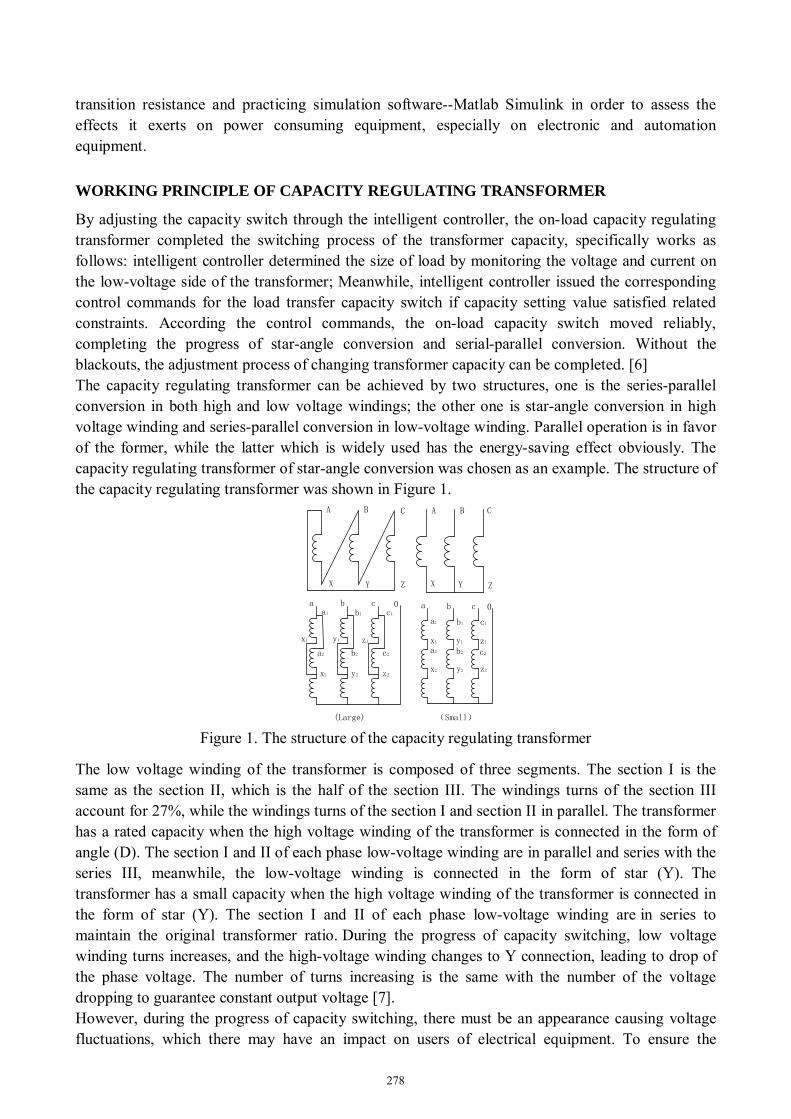
By adjusting the capacity switch through the intelligent controller, the on-load capacity regulating transformer completed the switching process of the transformer capacity, specifically works as follows: intelligent controller determined the size of load by monitoring the voltage and current on the low-voltage side of the transformer; Meanwhile, intelligent controller issued the corresponding control commands for the load transfer capacity switch if capacity setting value satisfied related constraints. According the control commands, the on-load capacity switch moved reliably, completing the progress of star-angle conversion and serial-parallel conversion. Without the blackouts, the adjustment process of changing transformer capacity can be completed. [6] The capacity regulating transformer can be achieved by two structures, one is the series-parallel conversion in both high and low voltage windings; the other one is star-angle conversion in high voltage winding and series-parallel conversion in low-voltage winding. Parallel operation is in favor of the former, while the latter which is widely used has the energy-saving effect obviously. The capacity regulating transformer of star-angle conversion was chosen as an example. The structure of the capacity regulating transformer was shown in Figure 1.
A BC
X YZ XY Z
AB C
a b c 0 a b c 0a1
a2
x2
x1
b1
y1
b2
y2
c1
z1
c2
z2
a1
x1
a2
x2
b1
y1
b2
y2
c1
z1
c2
z2
(Large) (Small) Figure 1. The structure of the capacity regulating transformer
The low voltage winding of the transformer is composed of three segments. The section I is the same as the section II, which is the half of the section III. The windings turns of the section III account for 27%, while the windings turns of the section I and section II in parallel. The transformer has a rated capacity when the high voltage winding of the transformer is connected in the form of angle (D). The section I and II of each phase low-voltage winding are in parallel and series with the series III, meanwhile, the low-voltage winding is connected in the form of star (Y). The transformer has a small capacity when the high voltage winding of the transformer is connected in the form of star (Y). The section I and II of each phase low-voltage winding are in series to maintain the original transformer ratio. During the progress of capacity switching, low voltage winding turns increases, and the high-voltage winding changes to Y connection, leading to drop of the phase voltage. The number of turns increasing is the same with the number of the voltage dropping to guarantee constant output voltage [7]. However, during the progress of capacity switching, there must be an appearance causing voltage fluctuations, which there may have an impact on users of electrical equipment. To ensure the
278

transformer without losing power and reduce voltage fluctuations, transition resistance in series is needed in the high and low voltage winding. When the switch moving contact from a file without completely left, transition circuit is turned (resistor limits the current by the transition between two steps) to ensure the transformer without losing power. When the moving contact reaches the other files, then cut the transition circuit, completing the adjustment process.
SIMULATION MODEL
According to the working principle of the capacity regulating transformer, the mathematical model was built, and the transition resistance was analyzed in the process. The mathematical model of the transformer is shown in Figure 2.
A
B
C
Load A
Load B
Load C
1
22
2
3
23
4
24
6
10
713
25
11 26
148
915
12 27
Figure 2. The simulation model of the capacity regulating transformer
The simulation model of the capacity regulating transformer can be included as follows: the transformer model, switch model, switch control module, transition resistance model and power supply module. 1) Transformer model. Multi-winding transformer model in the Simpower system was adopted. The single phase SN=315kV-A, U1 / U2 = 10500/400V, the rated voltage ratio on the high and low voltage side was set to [10500 292.76 292.76 107.24], and magnetizing impedance p.u. respectively was set to 50, 50. 2) Switch model. The ideal switch in Simpower System was adopted, the internal resistance was set to 0.001 with the initial state setting by 0 or 1; the transition resistor was set to 1; the transition
capacitor was set to 1 Fµ . In both the high and low voltage side the transformer single-phase, 3
switches was adopted to achieve the star-angle conversion in the high-voltage side and series -parallel conversion in the low-voltage side. 3) Switch control module. By using the control time sequence module, the switch in the high and low voltage side can be changed. Figure 3 shows the sequence of switches for this paper. 4) Transition resistance model. During the process of building the model, the transition resistance was considered. The transition resistor settings in phase A is shown in Figure 4.
279

t/s0.02 0.025 0.03 0.035 0.04 0.045
high-voltage
side
Switch1.3.5
Switch2.4.6
Switch22.23.24
Switch7.8.9
10.11.12
Switch13.14.15
Switch25.26.27
1
1
1
1
1
1
0
0
0
0
0
0
low-voltage
side
Figure 3. Switch control time sequence
TRa
TRA
Figure 4. Transition resistor settings in phase A
At the high-voltage side, the transition resistor TRA was set to 450, and transition resistor TRa at the low voltage side was set to 2. 5) Power module. 50Hz AC power was adopted and the amplitude was set to 8164V.
RESULTS AND ANALYSES
During capacity regulating transformer switching, switch operation can result in voltage fluctuation on low-voltage side. After adding transition resistors, the voltage fluctuation range during capacity switching will decline sharply[8]. And various transition resistor value, transformer capacity and load have different influence on the voltage fluctuation range. Based on the model mentioned above, the process of capacity switching from the large to small was simulated. Transition resistor parameters
(1)Transition resistor on low-voltage side Lr
With the transformer capacity of 315kVA, load power of 100kW, and transition resistor on high-voltage side of 450Ω,simulation was carried out with different transition resistors on low-voltage side of 2Ω, 5Ωand 8Ω. The voltage curves in low-voltage side is showed in Figure 5.
(2)Transition resistor on high-voltage side Hr
With the transformer capacity of 315kVA, load power of 100kW, and transition resistor on low-voltage side of 2Ω,simulation was carried out
280

Voltage on Low-
voltage side(V)
Voltage on Low-
voltage side(V)
Voltage on Low-
voltage side(V)
Time(S)
Time(S)
Time(S)
600
400
200
0
-200
-400
-600
-800
-1000
600
400
200
0
-200
-400
-600
-800
-1000
600
400
200
0
-200
-400
-600
-800
-10000 0.01 0.02 0.03 0.04 0.05 0.06 0.07 0.08
0 0.01 0.02 0.03 0.04 0.05 0.06 0.07 0.08
0 0.01 0.02 0.03 0.04 0.05 0.06 0.07 0.08
(a) =2Ω
(b) =5Ω
(c) =8Ω
Figure 5. Transformer transient voltage on low-voltage side
( Lr =2Ω、5Ω、8Ω)
with different transition resistors on low-voltage side of 400Ω, 450Ωand 500Ω. The voltage curves on low-voltage side is showed in Figure 6.
Voltage on Low-
voltage side(V)
Voltage on Low-
voltage side(V)
Voltage on Low-
voltage side(V)
Time(S)
Time(S)
Time(S)
600
400
200
0
-200
-400
-600
-800
-1000
600
400
200
0
-200
-400
-600
-800
-1000
600
400
200
0
-200
-400
-600
-800
-10000 0.01 0.02 0.03 0.04 0.05 0.06 0.07 0.08
0 0.01 0.02 0.03 0.04 0.05 0.06 0.07 0.08
0 0.01 0.02 0.03 0.04 0.05 0.06 0.07 0.08
(a) =400Ω
(b) =450Ω
(c) =500Ω Figure 6. Transformer transient voltage on low-voltage side
( Hr =400Ω、450Ω、500Ω)
Transformer Capacity With the load power of 100kW, transition resistor on high-voltage side of 450Ω,simulation was carried out with different transition resistors on low-voltage side of 2Ω, 5Ωand 8Ω. The voltage curves on low-voltage side is showed in Figure 7.
281

Power Load The transition resistors in low and high voltage side are set as 2Ω and 450Ω respectively. With transformer capacity of 315kVA, the power load are set as 100kW,200kW and 300kW respectively. The Figure 8 shows the low voltage side curves.。
(c)S=300kVA
(a)S=160kVA
Voltage on Low-
voltage side(V)
Voltage on Low-
voltage side(
V)Voltage on Low-
voltage side(
V)
Time(S)
Time(S)
Time(S)
600
400
200
0
-200
-400
-600
-800
-1000
600
400
200
0
-200
-400
-600
-800
-1000
600
400
200
0
-200
-400
-600
-800
-10000 0.01 0.02 0.03 0.04 0.05 0.06 0.07 0.08
0 0.01 0.02 0.03 0.04 0.05 0.06 0.07 0.08
0 0.01 0.02 0.03 0.04 0.05 0.06 0.07 0.08
(b)S=200kVA
Fig7 Transformer transient voltage on low-voltage side
(S=160kVA、200kVA、315kVA)
(c)P=300kW
(a)P=100kW
Voltage on Low-
voltage side(V)
Voltage on Low-
voltage side(
V)Vo
ltage on
Low-
voltage sid
e(V)
Time(S)
Time(S)
Time(S)
600
400
200
0
-200
-400
-600
-800
-1000
600
400
200
0
-200
-400
-600
-800
-1000
600
400
200
0
-200
-400
-600
-800
-10000 0.01 0.02 0.03 0.04 0.05 0.06 0.07 0.08
0 0.01 0.02 0.03 0.04 0.05 0.06 0.07 0.08
0 0.01 0.02 0.03 0.04 0.05 0.06 0.07 0.08
(b)P=200kW
Figure 8. Transformer transient voltage on low-voltage side ( P =100kVA、200kVA、300kVA) Analyses of simulation results According to simulation results, it is can be found that voltage sag on low-voltage side occurs during capacity switching. And the duration time is about 25ms. For the convenience of analyses, the concept of Voltage Fluctuation Rate is defined. Voltage Fluctuation Rate (VFR):
282

s m
s s
V VVVFRV V
−∆= = (1)
sV is steady-state voltage, and mV is the minimum voltage during switching.
(1)The cases of different resistance parameter It can be found that voltage fluctuation range is large when transition resistor on low-voltage side is 2Ω ,5Ω and 8Ω. After calculation , VFR is about 28%, 37% and 50% respectively. In Figure 6, VFR hardly change with different transition resistor values on high-voltage side. Therefore the conclusions can be obtained. With transition resistors in low voltage side increasing, VFR grows. The transition resistor on high-voltage side has little relationship with VFR. (2)The cases of different transformer capacity According to Figure 7, the voltage fluctuation range is small when the transformer capacity changes. VFR is almost unaffected by transformer capacity change. (3)The cases of power load It can be seen from Figure 8 that voltage fluctuation range is large when load is 160kW, 200kW and 315kW. It is calculated that VFR is 22%, 28% and 35% respectively. Therefore, the conclusion can be obtained that VFR increases gradually with the growing load.
IMPACT ANALYSIS ON CUSTOMERS
According to the simulation results it can be found that voltage sag problem occurs during the transformer capacity switching. Voltage sag is a decrease in rms voltage or current at the power frequency for durations of 0.5 cycle to 1 min. Typical values are 0.1 to 0.9 pu[9]. Voltage sags are the most widespread power quality issue affecting distribution systems, especially industries where involved losses can reach very high values. A short and shallow voltage sag can produce dropout of a whole factory. Many typical voltage sag curves have been proposed as guidelines, presented by institutions as the US Department of Commerce-Federal Information Processing Standards Publication no. 94, Computer Business Equipment Manufacturing Association (CBEMA), and the Information Technology Industry Council (ITIC). The current version of ITIC curve, revised in 1996, has reached widespread prominence. These guidelines are normally provided in graphical form, having two well bounded parts that correspond to the overvoltage and undervoltage withstand values. The curves represent an important tool for the manufacturer, user, and system designer. Besides, IEEE Standard 1346 provides voltage sag curves for several sensitive equipments. These equipments are PC, speed motor, programmable logic controller (PLC), variable frequency speed controller and AC contactor[10] . According to the voltage sag curves mentioned above, the influence on the specific equipments caused by the transformer capacity switching can be analyzed. And the voltage sag values(=1-VFR) are related to the voltage fluctuation range. Based on the simulation results, the voltage sag points of several situations were plotted in the typical voltage sag curves such like the lower leg of ITIC curves and PLC curves, showed in Figure 8
283

(a)Voltage sag curves with various transition resistors in low-voltage side
(b)Voltage sag curves with various transformer capacity and transition resistors in high-voltage side
(c)Voltage sag curves with various loads Figure 9. Voltage typical curves and points
According to simulation results, percentage to nominal voltage (=1-VFR) can be obtained. In the Figure 8(b), the upper point group varies along with transformer capacity. The lower group is with the transition resistor on high-voltage side. The figures show that the ITIC curve is the harshest. Because all the simulated voltage sag points are in the normal regions of speed motor, PLC, VVVF and AC Contactor except ITIC voltage curves. When transition resistor on low-voltage side equals to 2Ω,the voltage sag belong to the normal regions. The others don’t. Besides, the voltage sag has little relationships with the transition resistor on high-voltage side and transformer capacity. When the load is under 200kW, the voltage sag caused by capacity switching is inside the allowed range. Therefore these conclusions can be referred to avoid great impact on the power quality issue and customers.
CONCLUSION
This paper analyzes the working principle of transformer capacity switching. Considering the transition resistors in series, the mathematical simulation models are established in Simulink software. With different transition resistor parameters, various transformer capacity and load, some
284

conclusions are obtained. With transition resistors in low voltage side increasing, voltage fluctuation rate grows. However, transformer capacity and transition resistor in high voltage side don’t influent the voltage fluctuation rate, which increases along with the growing load. Finally the voltage sag in various simulation conditions was evaluated with the typical voltage sag curves.
REFERENCES
[1] WANG Jin-li. 2009. Application and Integrated Economic Analysis of On-load Capacity Regulating Transformer .High Voltage Apparatus 45(3):32-35. [2] CHEN Yu-Guo. 1998. Principle and Analysis of On-load Capacity Regulating Transformer. Transformer 35(1): 24-25. [3] FAN Wenbo, HAN Shaigen. 2011. A Control Strategy for Secure and Economic Operation of On-load Capacity Regulating Transformer.Automation of Electric Power Systems 35(18):98-102 [4] WANG Jin-li, Sheng Wan-Xing. 2009. Simulation Analysis of Capacity Regulating Transformer. Transformer 46(7): 19-23. [5] LI Xiao-hui,ZHAO-bin. 2010. LI Ying-hua. Analysis of Instantaneous Overvoltage and Overcurrent for On-load Capacity Regulation Transformer. High Voltage Apparatus 46(10): 32-35. [6] Harlow J H, Stich F A. 1982. An Arcless Approach to Step-Volatge Regulation. Power Apparatus and Systems, IEEE Transactions on (7): 2096-2102. [7] Zhang De-ming. 1996. On-Load Power Regulating Tap-Changer (6). Transformer 09:38-42. [8] JIA Ji-ying, FANG Heng-fu, LUAN Da-li, WANG Jin-li. 2013. Development of On-Load Power Regulating Tap-Changer . Transformer 10:40-44. [9] TAO Shun, XIAO Xiang-ning, LIU Xiao-Juan. 2005. Study on Distribution Reliability Considering Voltage Sags and Acceptable Indices. Proceedings of the CSEE Vol.25 No.21:63-69 [10] IEEE Recommended Practice for Evaluating Electric Power System Compatibility With Electronic Process [11] Bollen M H J, Sabin D D. 2003. Voltage-sag indices-recent developments in IEEE P1564 Task force. CIGRE/IEEE PES international Symposium , Canada.
285