the swimming pool and allied trades association · 2018-02-04 · necessary to be installed in a...
TRANSCRIPT
Spata Standards Volume Two (1999)
THE SWIMMING POOL
AND ALLIED TRADES
ASSOCIATION
STANDARDS FOR
SWIMMING POOLS
Domestic and Commercial
VOLUME TWO e Filtration Systems - Flow Control - Chemical Dosing - Water Treatment - Heating and Environmental Control - Covers and Air Enclosures - Electrical - Specialist Pools - Systems Design - Health and Safety - Operation and Maintenance

Spata Standards Volume Two (1999)
i e

Spata Standards Volume Two (1 999)
Standards for Swimming Pools
Domestic and Commercial
VOLUME I1 CONTENTS
Introduction
SECTION 1 FILTRATION SYSTEMS
General Principles
Filters
Equipment Specification
Filter Media
Water Circulating Pumps
Strainers
Recirculatory Systems and Flow Fittings
Balance Tanks
Pool Pipework, Valves and Fittings
SECTION 2 CHEMICAL DOSING
Water Treatment Methods
Design
Equipment Specification
SECTION 3 HEATING AND ENVIRONMENTAL CONTROL
Outdoor Pool Heating
Indoor Pool Heating
Air Distribution, Ductwork and Grilles

Spata Standards Volume Two (1999)
SECTION 4 COVERS AND AIR ENCLOSURES
Winter Covers
Solar Blankets and Heat Retention Covers
Cover Rollers
Care and Maintenance
Automatic and Motorised Covers
Inflatable Air Enclosures
SECTION 5 ELECTRICAL
General and Special Requirements
Electrical Heating and Underwater Lighting and Equipment
SECTION 6 SPECIALIST POOLS
Types of Pool
Hydrotherapy
Diving
Equine and Canine
Pool Accessories
Specialist and Leisure Activity Equipment
SECTION 7 SYSTEM DESIGN
Pool Criteria
Filtration
Flow Rates
Bathing Loads
Circulation and Water Turnover
Filtration Velocity and Filter Bed
Balance Tank
Pipework Sizing
Facilities for the Disabled

Spata Standards Volume Two (1 999)
SECTION 8 HEALTH AND SAFETY
During Construction
During Operation
Legal Requirements
SECTION 9 COMMISSIONING. OPERATION AND MAINTENANCE
Commissioning, Demonstration and Handover
Operation and Maintenance Manuals
Responsibility
SECTION 10 GLOSSARY AND ACKNOWLEDGEMENTS a

Spata Standards Volume Two (1 999)
Spata Standards Volume Two (1 999)
a INTRODUCTION
These standards describe and lay down parameters in detail for the specialist items of equipment necessary to be installed in a properly equipped swimming pool to ensure a clean, safe and inviting swimming pool. Expressed in its simplest form the filtration, water treatment and recirculating system is designed to remove water from the pool, filter it, disinfect it and return it back to the pool. Although often of highly technical complexity, these standards endeavour to describe as simply as possible the filtration equipment, water treatment equipment, heating and the recirculatory system.
The standards contained in this booklet are recommendations in the absence of any legal regulations. They are designed to complement the required rules, regulations and standards of:-
The Health and Safety Executive The English Sports Council (Sport England) Pool Water Treatment Advisory Group (PWTAG) Federacion Internationale (FINA) Amateur Swimming Association (ASA) British Standards Institute (BSI)
As such SPATA recommend that designs of all Swimming Pools either private or public are based on a
the parameters indicated as an aid to the goal of achieving safe healthy construction, operation and maintenance.
To facilitate understanding of these Standards any residential or private pool used solely by a family or invited guests is classed as a Domestic Pool.
ALL other pools, whether school pools, hotel pools, club pools, health club pools, therapy pools or leisure pools fall into the category of Commercial (Public) Pools.
In the absence of regulations the standards have been formulated using the experience and knowledge of a committee of SPATA members. During formulation it was found that in certain areas and for certain formulae, several quite valid variants were available and in these circumstances the standards shown are modal. It may be however, that in the interests of design, other formulae than the standards shown may be applied correctly.
These standards therefore do not preclude the use of alternative formulae or procedures where a specialist design may require such. SPATA acknowledge that with advances in technology new prod- ucts and design innovations will of necessity be introduced and procedures are in place to provide for consideration of these within future amendments to these standards.
It should be noted that in any design for swimming pools either private or public these standards can only offer recommendations for guidance purposes. Notwithstanding anything contained in these standards, responsibility for specific Health and Safety issues and compliance with legislation of COSHH, CORGI, HSE etc, must be taken into consideration in relation to any contract during design, construction and operation and will remain the responsibility of the parties involved. The importance of defining the requirement, the specification and the responsibilities (for the pool) rest with the reader.
Whilst every effort has been made to ensure the facts and figures in SPATA Swimming Pool Standards are correct, no individual member nor the Council of SPATA nor SPATA as a corporate entity can accept any responsibility for any errors or omissions. Nor does SPATA assume any responsibility to those who supply/provide/purchase/acquire/distribute or use products or systems which comply with or purport to comply with these standards. SPATA is a trade association. It does not hold itself out to be a regulatory body.

Spata Standards Volume Two (1999)

Spata Standards Volume Two (1 999)
SECTION 1
FILTRATION SYSTEMS
Including
FILTERS 0
WATER CIRCULATING PUMPS
RECIRCULATORY SYSTEMS AND FLOW FITTINGS
BALANCE TANKS
PIPEWORK, VALVES AND FITTINGS 0

Spata Standards Volume Two (1999)
,
Spata Standards Volume Two (1 999)
SECTION 1 - FILTRATION SYSTEMS
GENERAL
Water filtration is the passing of water through a medium which will retain the solids suspended in that water. In the context of swimming pools, the filtration system is understood to include the filters, the pumps, the flow fittings and the water circulation pipework valves and fittings all of which contribute to the filtration system.
This section therefore deals with 1. Filters 2. Pumps 3. 4. Balancetanks 5. Pipework, valves and fittings
Recirculatory systems and Flow fittings
FILTERS
There are six forms of filtration, which conform to the principle above.
i) ii) iii) iv) v) vi) Gravity sand filtration
Low rate pressure sand filtration Medium rate pressure sand filtration High rate pressure sand filtration Pre-coat filtration (pressure and vacuum) Disposable cartridge or fibre glass mat filtration
Of these the last is now rarely, if ever, used in swimming pool applications being generally used in effluent and potable water treatment and is, therefore not covered in this Standard.
SAND FILTRATION
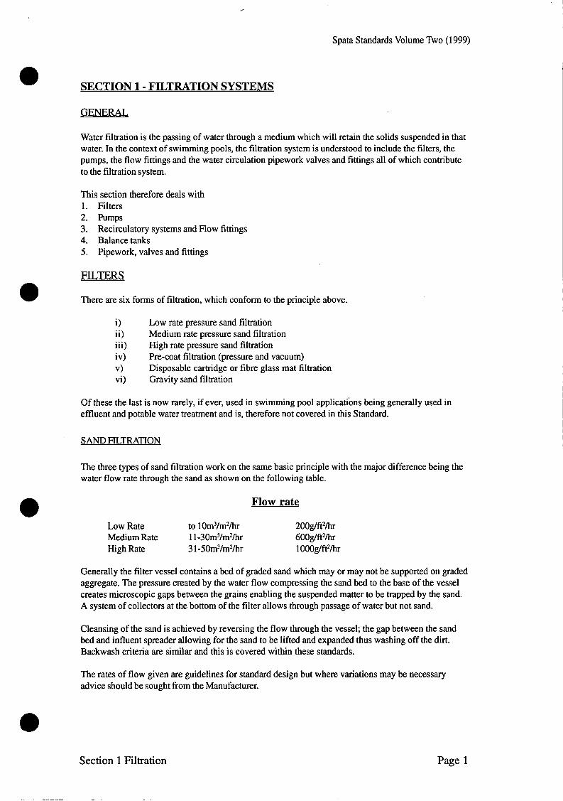
The three types of sand filtration work on the same basic principle with the major difference being the water flow rate through the sand as shown on the following table.
Flow rate
Low Rate to 1 0 m w / h r 200g/ft%r Medium Rate 11 -30m3/m2/hr 600g/ft2/hr High Rate 3 1 -50m3/m2/hr 1 OOOg/ftz/hr
Generally the filter vessel contains a bed of graded sand which may or may not be supported on graded aggregate. The pressure created by the water flow compressing the sand bed to the base of the vessel creates microscopic gaps between the grains enabling the suspended matter to be trapped by the sand. A system of collectors at the bottom of the filter allows through passage of water but not sand.
Cleansing of the sand is achieved by reversing the flow through the vessel; the gap between the sand bed and influent spreader allowing for the sand to be lifted and expanded thus washing off the dirt. Backwash criteria are similar and this is covered within these standards.
The rates of flow given are guidelines for standard design but where variations may be necessary advice should be sought from the Manufacturer.
Section 1 Filtration Page 1

Spata Standards Volume Two (1999)
LOW RATE FILTRATION
The filter media is a bed of fine silica sand which is supported on graded aggregate with Low rate filtration.
A flocculent is added to the sand bed with the object of creating a semi-permeable layer on the top of that sand bed, thus, stopping the penetration of the sand bed to any great depth. Once the filter reaches the theoretical saturation point the flow is reversed through the support media and the dirt washed away to waste. The filter should never reach saturation point and backwashing at least once a week should assist in this by controlling the TDS levels. Because of the heavy nature of the supporting media this is not disturbed and only fine silica sand is put into suspension during the backwash process. Thus the backwashing of the filter is possible at low flow rates which of necessity requires a large gallonage of water to effect proper cleansing of the media. The breaking up and lifting of both the flocculent and the sand bed is assisted by the use of an air scouring device operated pneumatically. This also helps to cut down the backwash time. The point at which the filter requires backwashing is determined by influent and effluent pressure gauges which show by means of the pressure differentials at the time of starting up and a pre-deter- mined pressure rise when it is necessary to effect backwashing. Low rate sand systems require a particle size of 0.83ml to 1.3ml with a uniformity coefficient of 1.45 - 1.69. The bed should generally be not less than 30Oml of clean uniform gravel or with composite beds not less than lOOml of each grade. Manufacturers recommendations should be sought.
MEDIUM AND HIGH RATE FILTRATION
Medium and high rate filtration differ from low rate filtration in that the water is passed through it at up to 50m3/m2hr (1000 gallons per square foot per hour). The filter is hydraulically designed to permit an even distribution of the water over the whole surface area of the sand bed. In these systems the dirt is allowed to penetrate the sand bed to a predetermined depth. Whilst the increased velocity generally dispenses with the necessity of an air scour to lift the bed, it should be noted that a reverse flow of approximately 30m3/m2/hr should be available for backwash. To enable efficient backwashing to take place there should be a minimum flow rate of not less than 36.70m3 per hour per m2 of filter area ( 750 gallons per hour per ft2 of filter area). Flow should be to a drain or manhole within 12m (50ft). If a further distance then pipe size will need to be increased to prevent back pressure. Medium and high rate systems require a particle size of 16/30.
Page 2 Section 1 Filtration

Spata Standards Volume Two (1 999)
a . PRE-COAT FILTRATION
A pre-coat filter vessel contains a number of frameworks or septums, which are covered with a durable, chemical resistant and porous material. The water flow is engineered so that the water enters the vessel, surrounds the septums and in order to leave the vessel must pass through them. The water flow characteristic should be such as to ensure the greatest uniformity of flow through each of the septums and thereby ensuring the filter medium is evenly distributed.
Filtration is achieved by coating the septums with a fine powder, of not less than 1.6mm (.0625ins) through which the water, of necessity has to pass.
The determination of the total filter area shall be the sum of the area coated on each septum and shall not be the area of material used to cover the septum.
The medium used is Diatomaceous Earth or Volcanic Ash. When the water flow stops some filter medium may fall of but the initiation of the water flow will replace it.
The filter medium is introduced to the filter by means of a ‘slurry pot’ fitted in the suction flow into the pump. The volume of medium is set by the filter manufacturer and should not be altered.
Backwashing is achieved by the same reversal of flow principle to cast the dirt, and in this case the medium, into a suitable drain.
a A pressure gauge should be fitted and a suitable air purging method incorporated in the design.
Particulate removal to 5 microns can be achieved.
Flow rates of 50m3/m2/hr or 1000g/ft2/hr are usual.
CARTRIDGE FILTERS
Cartridge filters use a system where the filter internal is re-usable. Once saturation point has been reached the cartridge is removed and cleaned or replaced if necessary. Continuing life will depend upon material of any contamination. These filters are generally used on small or specialised pools with low bathing loads. Removal to 5 microns can be achieved.
Section 1 Filtration Page 3
~

Spata Standards Volume Two (1999)
EOUIPMENT SPECIFICATION - mLTERS
STEEL TANKS
1. Filter tanks should be fabricated generally in accordance with BS Standards for pressure vessels
tanks should be built to withstand the working pressure equivalent to 1 ?h times the shut off head of the pump employed.
and
2. Pressure vessels should have a safety factor not only with regard to pressure, but also in relation to vacuum, and should be designed to withstand the crushing pressure developed under a vacuum of 50mm (2in) of mercury, with a safety factor of 3.5 or greater.
3. The filter underdrain should have an effective distribution of at least 25% of the cross section of the tank. Tanks placed underground should be steel plate designed and reinforced to cope with the addi- tional stresses in accordance with the manufacturers recommendations. All filter tanks should have an approved non-corroding interior and exterior coating, or should be fabricated from a non-corroding material (stainless steel, glass reinforced plastic, plastic).
4. All filters should be equipped with at least one pressure vacuum or compound gauge as applicable, which should be positioned in such a way as to determine the pressure rise or differential across the filter and to determine the need for cleaning.
5. All pressure filter systems should be equipped with pressure gauge(s) and an air relief valve at the high point of the system. All sand filters should be provided with a waste sight glass or other visual means to determine when the filter has been restored to its original cleanliness
6. Sand filter systems in accordance with the manufacturers design criteria, should be made and installed to operate at a minimum amount of backwash water passing through the filter, with or without the aid of compressed air or other devices to break up the sand bed and/or flocculate the water creating sufficient turbulence to ensure 100% efficiency within that period. .
7. All valves shall be clearly marked indicating their purpose and operation.
8. The overdrain of the high rate sand filter shall be hydraulically designed to ensure an even flow of water through the sand at the correct rate without channelling or turbulence taking place.
9. The underdrain system shall be designed to eliminate the possibility of any transference of sand between the filter and the pool and constructed in non corroding material.
10. All tanks shall be fitted with sufficient access or manholes of correct size to enable safe and correct servicing and loading of medium.
Page 4 Section 1 Filtration
Spata Standards Volume Two (1 999)
GRP PRESSURE VESSELS
With a GRP vessel the resinlglass ratio should not exceed 2 - 2.5 parts resin to 1 part glass by weight evenly distributed throughout the vessel and its design and method of fabrication shall be such that there shall be no resin rich area.
Tanks shall be hydraulically pressure tested to a minimum of 1.3 x Design pressure of tank for a period including a surge test of 60 minutes with a standard production lid or aperture sealing device. GRP tanks shall also be subjected to a re-cycling implosiodexplosion test to stimulate the switching on an switching off of the filter.
All glass reinforced plastic swimming pool filter tanks shall be:-
1. 2.
3.
4. In accordance with BS4994.
Of the permanently jointed type by means of glass and resin (i.e. one piece) With two or more parts suitable jointed by means of gasket or sealing 0 ring and secured by corrosion resistant bolts, set screws with nuts and washers or a ring. Free from sharp corners thin lips or rims at mating faces such as are commonly found in metal tanks incorporating quick release type clamping rings for jointing the two halves together.
PRE COAT FILTERS
Pre-coat filters, both pressure and vacuum, shall be correctly hydraulically designed and engineered so that there is a pre-coat of not less than 1.6mm (.0625in) of the filter septum. The pressure vessel should be manufactured from a suitable, durable and non corroding material and should have a suitable, resealing, jointing system to allow for the removal of the septums.
Both the tank and jointing system should be capable of withstanding a pressure of 1.5 times the shut off pressure of the pump used. Vacuum filter tanks should be able to withstand the pressure developed by the weight of the water contained therein and, in addition, should be able to withstand the crushing pressure developed under a vacuum of 500mm (20 ins) of mercury, both with a safety factor of 3.5 or the design factor, which ever is greater.
The determination of the filter area shall be made on the basis of a true and effective supported septum surface. In the case of fabric septum the area computations shall be made on a basis of measurements of the septum support in a reasonably constant plain. Area allowance shall not be granted for folds in the septum fabric or deviations in the septum which could easily bridge.
The tank containing the filter elements shall be constructed of steel, plastic, or other material which will satisfactorily provide resistance to corrosion with or without protective coating. Pressure vessels shall be designed for a working pressure equal to the shut off head of the pump with a safety factor of 1.5.
The filter elements shall be fabricated of corrosion resistant materials throughout. They shall be designed to be adequately resistant to a differential pressure between influent and effluent of not less than the maximum pressure which can be developed by the circulating pump, and shall be of adequate strength to resist any additional stresses developed during the cleaning operation. The filter septum on which the filter media is deposited shall be provided with openings, the minimum dimensions of which shall not be greater than 0.13mm (0.005in).
Provision shall be made to introduce the filter media in to the filter in such a way as to evenly pre-coat the filter septum before the filter is put into operation. The amount of filter aid shall be selected to provide at least the same protection to the filter septum as will be provided by the use of 780 grams per m2 (0.15 lbs per ft2) of diatomaceous earth per filter area. Where crushed volcanic ash, or the equiva- lent, is used in lieu of diatomaceous earth filter media, then the ratio shall be related to the bulk and not to the weight. 520 grams per m2 of filter area (0.1 lbs per ft').
Section 1 Filtration Page 5

Spata Standards Volume Two (1999)
FILTER MEDIA
LOW RATE SAND SYSTEMS
1. Filter sand should be a hard uniformly graded mineral free silica material with effectively particle sizes between 1.3mm and .83mm (.05in and .033in) with uniformity co-efficient of 1.45-1.69. There should be no limestone, or deleterious matter present. Other types of filter media are acceptable providing the particle size is within 0.3mm (0.012in) of that specified for sand and a uniformity of 1.75 maximum, and will not deteriorate or dissolve under normal use.
3. Filter and freeboard should be sufficient to enable a satisfactory backwash without loss of sand. 4. There should be not less than three grades of gravel or suitable supporting media which should be
clean, uncrushed, rounded, non-porous incalcareous material. 5. The total depth of the gravel supporting bed should not be less than 30Omm (12in) and each grade
should be lOOmm (4in) or more in depth. Each layer of gravel should be level to prevent the intermixing of adjacent grades. The top layer should vary in size between 2.5mm and 1.25mm (.lin and .05in). The next layer should vary in size between 6.4mm and 2.5mm (.25in and .lin) the bottom layer should vary in size behveen 12.7mm and 6.4mm (.05in and .25). Sand filters with varying depth of filter bed, specially engineered underdrain systems and fewer layers or less depth of supporting gravel media, will be deemed acceptable providing their field use and design criteria are in accordance with manufacturers claims.
2.
6.
m D I U M AND HIGH RATE SAND SYSTEMS
With medium rate filtration, the bed consists of a pea gravel base of approx 2530% of total media supporting the remaining 70-75% of silica sand with high rate filtration the sand bed is of a constant size particulate grade of silica sand throughout and support media is not used. The filter is hydrauli- cally designed to permit an even distribution of the water over the whole surface area of the sand bed. In these systems the dirt is allowed to penetrate the sand bed to a predetermined depth.
Medium and high rate sand filter systems shall be designed and installed to operate at a rate not exceeding 50m3 per hour per m2 of filter area (1000 gallons per hour per ft2 of filter area) and capable of filtering down to approximately 7/10 microns.
Nothing in these standards shall preclude the use of an alternative medium to a silica medium providing that its use conforms to the requirements laid down by the filter manufacturers and produces the water quality required.
FILERAIDS
COAGULANT FEEDERS
A pot type coagulant (slurry) feeder or a positive solution feeder may be provided for feeding a coagulant solution to the filter influent. A flow through the feeder shall be induced proportionate to the filter influent, for introducing the coagulant to the filters. The pot shall be of approved design and shall be complete with control valves, one of which should be a needle point type, should be not less than 57 grams (202) or nut alum or sodium aluminate per 0. lm2 (lft’) of filter bed area.
Where a coagulant has been used then an air scourer should be provided to assist in the breaking up and cleansing of the coagulant and sand bed on the backwash cycle, and reduce the backwash water required.
Page 6 Section 1 Filtration
Spata Standards Volume Two (1999)
WATER CIRCULATING PUMPS
The swimming pool pump is the heart of the circulation system and thus design is of paramount impor- tance. Design of size, type and capacity should be calculated in accordance with the required flow rate taking full account of any head loss. Sufficient ventilation must be afforded within the plant room.
Each pump should be mounted on a plinth and the use of anti vibration pads or mountings should be considered on commercial or sensitive applications.
Each pump should be fitted with isolation valves to permit removal for servicing and non return valves should be fitted on commercial applications to prevent back pressure. In commercial applications, it is also good practice to provide a standby pump where 3 50% duty pumps are available. Design should permit each of the 3 pumps to function with each other for rotational use. Pumps should be manufac- tured in non corrodable materials with non corrodable impellers and chemical resistant seals. An integral coarse strainer or a separate prefilter should be incorporated with all swimming pool pump installations.
Pumps should be sited below water level wherever possible, but where it is necessary to site above water level a self priming pump must be fitted and the total lift required should be calculated in the vertical plane. Where pumps are site above pool water level, pipework should be laid below water level as far as possible to rise to the pump as closely as possible and minimise vertical water lift.
a RECOMMENDED STANDARDS
The installation of all circulating pumps shall be in accordance with these standards. Pumps shall not be over sized in attempt to decrease the turnover period by increased flow rate in excess of the filter manufacturers design criteria. Calculations shall at all times take into account the friction head loss throughout the whole system.
1. Units shall be protected against damp and rust. 2. The duty of the pump must be specifically designed to the system head of the complete filter
installation and the design characteristics of the filter. 3. Pumps incorporated into the filtration system should not be required to do other duties where
ancillary equipment fitted. A separate pump should be fitted for any ancillary equipment. 4. The works and services to the pump influent and from the pump effluent point shall be designed to
ensure that the pump operates at all times in accordance with the manufacturers specification, and within the performance curve. It should be ensured that performance is not adversely affected by cavitation, restricted return flow or frictional head loss. Noise insulation -Where installations of pumps are made adjacent to or inside residential build- ings or where noise could be aggravating environmental factor, then insulation against noise shall be provided in the form of anti vibration mats or insulation. In commercial applications the provision of a standby pump is recommended or alternatively 3 x 50% duty pumps. In level deck design the use of 2 No 50% duty pumps to enable connections to both the main drain and the balance tank is recommended. The use of a non return valve on the suction side of an undersized pump is unacceptable. The pump should be replaced with the correct size. The electrical controls and connections of all pumps should be installed in accordance with the current IEE regulations.
5.
6.
7.
8.
9.
Section 1 Filtration Page 7

Spata Standards Volume Two (1999)
STRAINERS
With all types of filter p n t , a suitable strainer or screen s..all be used to remove solids, debris, hair, lint etc.
Where a wet well is provided, the strainer shall consist of removable screens through which all water entering the pump will pass. Where no wet well is provided or where the suction cleaner or any other suction line is piped directly from the pool to the pump, pot type strainer, with removable strainer basket, shall be provided.
The strainer basket shall of rigid construction sufficiently strong to prevent collapsing when clogged. It is recommended that one spare strainer basket shall be provided. Any type of screen or strainer basket shall be fabricated of a corrosion resistant material or shall have a protective coating of such material.
Screens or strainer baskets shall have a maximum opening not greater than 75% of the maximum dimensions of the solids which will pass through the pump impeller without clogging and the .total clear area of all openings shall not less than 10 times the area of the largest size pipe from the pool to the strainer influent pipe.
BACKWASH
There are 3 main points to be addressed when designing the filter backwash system.
- The ability of the pump to raise the filter bed and correctly cleanse the media. Filtration velocity for backwash should not normally be below 30m3/m2/hr but manufacturers instructions should be taken into account. The capacity of the drainage system which should be sized to cope with 10% above the maximum backwash rate. The availability of water for the backwash either from the pool or the balance tank. Note -It is recommended that a central drain be sited on the plant room of a commercial installa- tion floor with an automatic sump pump.
-
- -
Page 8 Section 1 Filtration

Spata Standards Volume Two (1999)
RECRCULATORY SYSTEMS AND FLOW FITTINGS
Although there are many forms of recirculatory systems these standards will describe only the basic principles.
Water is drawn both from the surface and from the bottom of the pool, and is returned into the pool at a predetermined rate. The object is to achieve the greatest possible mixture of the recirculated water, keeping fine matter suspended and at the same time removing safely both from the surface and the deeper parts of the pool in a way that will avoid any dead spots (i.e. water which because of the inefficiency of the recirculatory system is not disturbed by that system).
The removal of the water from the surface of the pool is an important factor as 70-75% of impurities e.g. body oils, in the water are found within the top 75mm. This is achieved by one of the undermentioned systems.
1. 2.
Use of surface water skimmers which remove the debris from the surface by surface tension. Deck level pools, which operate under the same method. (Various designs are available and shown in detail in Volume 1).
~
No matter how effective these systems may be, inevitably certain extraneous matter sinks to the bottom. The generally accepted methods for removal of debris are either an underwater vacuum cleaner or an automatic mechanical cleaning system.
A properly equipped pool will contain the following recirculatory fittings:-
1.
2.
3.
4.
Drains located at the deepest point of the pool (with suction to ensure velocity is not likely to endanger bathers). Surface water skimmers or Overflow channels when deck level design is used with suitably designed outlets to the balance tank (see balance tank). Return inlets, sized accordingly to the flow rate volume and the general design criteria of the system. Suction point for an Underwater cleaning device.
Note - Siting the flow fittings is of particular importance to ensure maximum circulation and design needs to address not only water flow, bathing load and filtration factors but also size, shape and depth of the pool.
These standards require that both flow and return fittings and pipework to the pool operate at 100% of the water turnover rate. Therefore the total volume of water turning in one hour must be permitted through the recirculatory system. To ensure this the following criteria are recommended.
RETURN INLETS
Inlets should be capable of passing the total design flow rate (100%)
1.
2. 3. 4.
Water inlets and fittings should be constructed of non-corroding material and protected by a suitable grille with a maximum width between bars of 8mm. Screws and fittings should be tamper proof with secure face plates. Inlets should not protrude in the pool and no sharp edges or corners should be evident. Except when provided as a massage jet or rapid flow inlet, no inlet should provide a velocity greater than 2.4/2.745m/sec in private pool conditions, 1.5-2dsec in commercial pool conditions and .5dsec where turbulence may present a problem.
Section 1 Filtration Page 9

Spata Standards Volume Two (1999)
e 1.
2.
3.
4.
5.
6.
SKIMMERS
The skimmer should be manufactured of a material of lasting quality stressed to withstand concrete compression where applicable
Where more than one skimmer is employed, the pipe sizing shall be so balanced as to ensure the optimum efficiency of each skimmer at all times.
It should be possible to control each individual skimmer at all times.
Except where the skimmer is specially designed as a portable separate unit, skimmers should be built into the pool walls. All skimmers should be designed to substantially assist in the removal of floating oil and other flotsam and should meet the following requirements.
A floating weir (hinged or circular) should be provided which should establish the water level at which it overflows into the skimmer chamber, and this weir should have a free self adjusting range in elevation of not less than lOOmm (4") during which range it will be fully effective in acting as a weir, thus creating a differential in the level of the water in the pool and the level of water in the skimmer chamber.
An easily removable and cleanable skimmer basket, through which all skimmed water must pass should be provided to trap hair, lint and other large solids which might cause damage, should they pass through into the pump.
On a skimmer system - recommendations are for 70% - (surface) 30% (main drain) ratio. 70:30
On a level deck system this recommendation changes to a minimum 50%:50% ratio to a maximum 80%:20% ratio.
A Flow rate of 4.5m3/hr is provided on a 1 '/z " suction line, (per skimmer unit), If 2" suction pipe is used 9.5m3/hr can be achieved.
OR
CHANNELOUTLETS
Sufficient outlets, dependant on turnover and usage should be introduced into the channel. In commer- cial pools with heavy bather loads it may be preferable to introduce sufficient outlets to provide for 100% of water turnover. Where the balance tank is connected to the pool additional outlets can be provided directly above this tank.
Page 10 Section 1 Filtration

Spata Standards Volume Two (1999)
MAIN DRAINS (SUMPS)
1. The main outlet drains should be constructed of non corroding material, and each should be protected by a suitable grille or similar covering. The maximum distance between the bars of the grille must not exceed 8mm (6/16in) or the equivalent where a perforated grille is used. The flow of water through the total effective area of each grille should not exceed 30Omm (lft) per second. At least two outlets should be provided at the lowest point of the floor to drain the entire floor area completely. The spacing between 2 main drain outlets should not be greater than 2m apart on centres and not more than 3m from each side wall. Where despite splitting of velocity, any possibility of danger remains to bathers from the main drains, it is strongly recommended (particularly in shallow teacher pools) that an anti vortex plate should be fitted over the main drains in place of the grille. This anti vortex plate will preclude any remaining possibility of suction effect on the human body.
5. Both anti vortex plates and sump grilles should be securely fixed to prevent removal by unauthor- ised persons.
6. Water flow around the outlets should not exceed 0.5ds.
For safety reasons, it is recommended that the flow rate for the sump is split between at least 2 sumps to ensure velocity is not such to create a danger to bathers. The size of the grille should be as large as possible creating a slow even flow through a large area and thus preventing entrapment. A grille gap of 8mm max is advised. Water flow at the sump should not exceed OSdsec and the following formula can be applied to calculate this velocity:-
2.
3.
4.
Velocity d s e c = Circulation rate (m3/hr)
Free open area of grille (m2) x 3600
VACUUM FITTINGS
Vacuum fitting(s) shall be located in an accessible position(s) below the water line and shall be constructed of non corroding material. A sealing plug should be fitted when not in use.
Section 1 Filtration Page 11

Spata Standards Volume Two (1999)
BALANCE TANK
The sizing of the Balance Tank will depend on several, often conflicting, criteria. The tank is provided to hold a volume of water, in excess of the pool volume, to compensate for the displacement of water when bathers enter the pool.
It must, therefore be large enough to take the total displacement of the maximum design load entering the water at one time.
As bathers are prone to moving it must have the capacity of receiving a surge of water which, because of wave action, may be larger than the displacement volume. An additional volume must be added to the displacement volume. It is impossible to calculate accurately this volume and of course a safety margin must be included. The tank must also be large enough to allow access for maintenance and cleaning.
The position of the tank may well, in part, dictate its dimensions. One built into the pool structure may be oversized while a separate tank may well be smaller.
Design of the balance tank should take into account:-
- Bathing load - Use of the pool - Backwashing requirements - - Tank cleaning requirements
Health and Safety requirements (2 manhole access points for commercial installations)
It is widely accepted that the average displacement of a ‘standard’ body is about 60 litres and that in shallow water the displacement is approximately 75% of that figure. Consequently displacement volume starts to be calculated. There are several formulae for calculating the volume of the balance tank; none can be totally accurate and some are laid out in the Appendix.
The following formula (Rule of 3) is based on experience but does not preclude the use of others. Both PWTAG and DIN offer alternative formulae which are equally acceptable subject to specific require- ments.
The formula base is Length x Width x X. The total of this sum is the base capacity which becomes 1/3 rd of the total required balance tank area.
X can be deduced by using the following table
Commercial pool with excessive activity Commercial pool with play/water features Commercial pools (swimming only) Private pools 15-25 litres
75-100 litres 50-75 litres 25-50 litres
We can therefore substitute X as desired i.e. 25m x 12.5m = 300 (300 x 50) = 15,000 litres
15,000 = 15m3 The base capacity is therefore one third = 15m3 If we add on a third for surge capacity 15m3 Plus a third safety capacity 15m3 The total capacity 45m3
Page 12 Section 1 Filtration

Spata Standards Volume Two (1999)
It is very important that the tank is adequately sized for the use of the pool. If selecting a lower capacity within the relevant range, any possible practical problems should be considered. These include:-
. e
- Heavy bathing activity causes overflow and the displaced water will take time to get back to the pool. Pump sizing needs to be addressed to ensure sufficient flow is available to return this water from the balance tank to the pool at a reasonable rate. When lengthy backwashing takes place the water level may drop too far down the balance tank. Unless an automatic low control is fitted to cut off the pumps, air can be pulled through the pumps or a delay in backwash caused due to automatic shut off. If all backwash water is to be taken from the balance tank and not the pool, consideration should be given to fitting a bypass fill line to by pass the automatic top up and fill the balance tank prior to backwash. If the base capacity of the balance tank is insufficient for backwashing purposes then either a top up tank or a balance line between the main pool and the balance tank can be fitted under control of a ball valve. PumDs - If a single pump is fitted this pump will cut off when the water drops too low in the balance tank. If the design of circulation provides for 50% through the sump and 50% overflow then one pump can be fitted to the sump and one pump to the balance tank. Should low level cut off the pump to the balance tank then 50% circulation will remain available from the sump. 100% can still be achieved if a balance line between the pool and balance tank has been fitted. With correct valve design and use, then both pumps can be used from the main pool to ensure 100% pumping capacity.
-
-
-
-
-
Once the volume has been decided the design of the tank should take into consideration the construction criteria laid down in Volume 1 of these Standards.
The balance tank of a commercial pool should be constructed in steel reinforced concrete to the equivalent strength of the pool (see Volume 1). A residential pool may have a balance tank small enough to enable the use of a specialist non corroding underground tank.
The tank should preferably be sited between the plant room and the pool, often as an extension to the deep end of the pool. A commercial installation should be fitted with two easy access manholes where the tank will exceed 5m in length. It is recommended that consideration be given to siting access traps over pipework fittings where possible for ease of future maintenance.
Controls should include a safety overflow with outlet to a suitable place,(preference would be to site where any overflow would be noticed) a flow switch to provide for automatic water top up, a level indicator and a float operated control suction valve. Consideration should be given to a balance line with a ball valve or a by pass fill line.
Circulation to/from the balance tank should include a Non Return Valve between the tank and the plant room and connection of one filtration pump directly to the tank to ensure adequate circulation is achieved from the tank and not simply from the pool sumps. The use of two pumps will also provide for independent circulation from either the overflow channel or the sump in cases of emergency/ maintenance etc.
It is equally important to ensure that the surge channel and outlets thereto are correctly sized (see system design). The surround channel must be of sufficient size to accommodate the overflow and have sufficient drain off points into the tank to allow for a rapid evacuation of the channel. It is interesting to note that a 25mm rise in a 25 metre by 12.5 metre pool displaces 7.8m3 water and a 300mm by 300mm channel around such a pool has a capacity of 7.8m3.
Section 1 Filtration Page 13

Spata Standards Volume Two (1999)
POOL PIPEWORK. FITr"GS AND VALVES
Design of the pipework is critical to the correct operation of the pool and plant. Pipework should be of sufficient size to enable the flow fittings, the pumps and the filtration plant to operate as designed without causing restriction or friction headloss.
When designing underground pipework, thought should be given to future maintenance and pipework ducts should be situated as far as possible where inspection can be undertaken.
Similarly, care should be given to ensure thorough cleaning of surfaces before connections and use of the correct adhesives when solvent welding. When using cleaner and solvents ensure the area is well ventilated to comply with the health and safety requirements. Ensure also that empty cans are disposed of safely.
PIPEWORK SIZING
- - -
Suction Velocity (maximum 1.2 metredsec) Return Velocity (maximum 2.0 metreslsec) Grille Velocity (maximum 0.3 metredsec)
The minimum internal diameter of the pipe to be used for a given flow can be calculated using a single expression and knowing whether the pipe is on the suction side of the pump.
(See System DesigdAppendix)
WOMMENDED STANDARDS
1.
2.
3.
4.
5.
6. 7.
8.
9.
Pool pipework should be sized to permit the rated flow for filtering and cleaning without exceed- ing the maximum head at which the pump will provide such flows. In general the water velocity in the pool piping should not exceed 3m (loft) per second, unless summary calculations or measurements are provided to show that rated flows are possible with the particular pump fitted and pipework installed. All pipework, pool fittings, and works and services generally within the pool project shall be of non corroding PVCIABS. Class C (6 bar) is considered suitable for standard residential use whilst for underground pipework for commercial pools and in cases of specific stress Class E (16 bar) should be used. All solvent joints and connections should be cleaned and prepared to ensure a clean, leakproof resistant seal can be achieved specialist jointing compound is recommended of the type of pipework should be used. Metal fittings are to be used to connect different types of pipework. Where pipework is to be laid underground or in trenches due regard is to be paid to the bedding
.and backfilling of such trenches, which should be pea gravel or similar to prevent damage or movement to the pipework. Relevant BS and DIN standards are listed below:- - Imperial Pipe - Imperial Fittings - BS350516 - Metric Pipe - Metric Fittings - Threaded Fittings - Solvent Cement
- BS4346 Part 1
- DIN 806112 - DIN 8063, IS0 727, KIWA 54, UN1 7442175
- BS21, DIN 2999, IS07 - BS4346 Part 3
Underground water pipe should be NDPE approved. 10. ABS should not be used when ozone is designed into the system. 11. Pipework should be supported at suitable intervals and in any case not more than lm runs.
Page 14 Section 1 Filtration

Spata Standards Volume Two (1 999)
Valves appropriate to the installation shall be fitted throughout to ensure the proper functioning of the filtration and piping system. When the pump is below the overflow rim of the pool:-
1.
2.
3.
Valves shall be installed on the vacuum, main suction line and main skimmer line, and located in an accessible position outside the walls of the pool. A valve shall be installed on the main delivery line located in an accessible position outside the walls of the pool. Valves shall be made using non corroding material and dissimilar metals shall not be used. Where this is inevitable, a sacrificial anode shall be introduced into the system to prevent electrolysis taking place. When selecting valves, water treatment particularly ozone should be taken into account. Combination valves and ‘butterfly’ valves may be installed if the material and the design comply with the intent of these standards. Multiport valves are acceptable when fitted singly (usually private installations). Automatic backwash valves are acceptable providing their design criteria comply with the backwash requirements for the filter.
4. 5.
6. 7.
EOUIPMENT SPECIFICATION
Heavy duty plastic pipework in accordance with BS3505 should be incorporated for the pool and plant room pipework. UPVC or ABS are considered most suitable. Whilst it is preferable to lay underground circulation pipework in ducts etc. Where underground buried pipework is unavoidable, care must be taken in the choice of materials to be used. Fittings should be in accordance with BS4374.
PIPEWORK TESTING
All pipework shall be hydraulically tested to a minimum pressure of 10-15 psi (residential) or 35-45 psi (commercial) with a maximum equivalent to 1 ?4 times the shut off head of the pump and this pressure shall be maintained for a period of 30 minutes. A certificate to this effect shall be provided by the installing contractor is so requested by the client. (See Appendix B)
Section 1 Filtration Page 15
Spata Standards Volume Two (1999)
HLWTION - MISCELLANEOUS
The use of water is controlled by the Water Authority and it is important that current Water regulations and bye-laws are considered and adhered to. Current regulations include the following:-
1.
2.
3.
4.
5 .
Direct connection to public utilities, main water supply and main drainage is generally unaccept- able as no direct mechanical connection shall be made from the source of domestic water supplied to a swimming pool or to the piping thereof. Some local authorities however will accept the use of a double check valve, thereby eliminating any connection to what may become a source of con- tamination. The water supply for filling the pool, when derived from a domestic water supply, shall be by means of an overfill spout or hose or via a break tank, if no double check valve is permitted. Wherever any waste from the swimming pool is connected to a sewer or to a surface drain, an air gap or a relief manhole shall be provided which will positively preclude any surge or backflow from introducing contaminated water into the swimming pool or the water treatment plant. Every circulating system on public swimming pools shall be provided with a rate of flow indica- tor, with the activating element, installed with adequate clear distance up stream and down stream, to obtain a degree of accuracy within +5%. In sand filter installations the rate of flow indicator shall be on the pump discharge line leading to the filters and shall be calibrated for, and provided with a scale reading in litres per minute or gallons per minute and shall have a range of at least 10% below the established.
Page 16 Section 1 Filtration

Spata Standards Volume Two (1999)
a
SECTION 2
CHEMICAL DOSING
a

Spata Standards Volume Two (1999)
a
a
a

Spata Standards Volume Two (1999)
SECTION 2 - CHEMICAL DOSING
WATER TREATMENT
The water treatment or chemical dosing of the swimming pool is dealt with in detail in Volume 3. ‘Water Treatment and Chemicals’ where selection of the correct system and chemicals is discussed in detail. This volume concerns itself purely with the installation, operation and maintenance requirements applying to type of system using the chosen sanitiser and pH control agent.
WATER TREATMENT METHODS
DOMES TIC POOLS
The water balance of these pools can be controlled by hand dosing, semi automatic or fully automatic methods.
In all cases, the operator of the pool must be fully conversant with not only safe procedures but with effectiveness of these procedures. Dosing and Water Testing procedures should be demonstrated thoroughly and written instruction worded simply and effectively should be provided. Particular reference should be made to the dangers of:-
1. Mixing Chemicals 2. Incorrect storage 3. Changing chemical containers 4. Permitting children access to chemicals
COMMERCIAL POOLS
These recommendations are in accordance with PWTAG guidelines, whilst incorporating specific points directed at those who design, install and operate swimming pool dosing equipment.
Fully automatic dosing is the recommended method for all commercial pools, should other systems be provided a greater level as management and supervision will be essential.
The selection of sanitiser and pH agents must be considered in conjunction with Volume 3 but with bearing to the incoming water analysis and prospective use of the pool.
In all cases, the operator of the pool must be fully conversant with not only safe procedures but with effectiveness of these procedures. Dosing and Water Testing procedures should be demonstrated thoroughly and written instruction worded simply and effectively should be provided. Particular reference should be made to the dangers of:-
1. 2. Incorrect storage and handling 3. Incorrect containers 4. Untrained and inexperienced operators 5. 6. Incorrect ordering 7. 8.
Mixing chemicals and incorrect identification of required chemicals.
Incorrect, inadequate or inefficient water testing
Incorrect maintenance, topping up containers, sloppy cleaning up etc. Lack of Maintenance on safety equipment
Section 2 Chemical Dosing Page 1
Spata Standards Volume Two (1999)
RECOMMENDED STANDARDS
DESIGN
Whenever chemicals are in use there is a hazard. To minimise such hazard the following points should be addressed:-
1.
2. 3.
4. 5. 6.
7.
8. 9.
10.
11.
12.
13.
14.
15.
Siting of day (and bund tanks) of different chemicals must be sufficiently separated to prevent cross contamination and possible explosion, fire or gaseous exchange. Ideally a dividing wall could be used. They should be bunded (ie walled round) to collect any spillages. All chemical pipework, suction and delivery lines and tanks should be marked to meet regulations and to identify the exact contents. Pipes should be labelled with the direction of flow as well as coded for their contents. Pipes and their connections should have different fittings for different chemicals where possible. Dosing equipment should be designed to shut down should the pool circulation system fail. All systems should be installed and identified so that written work procedures can be followed safely. Suction lines, dosing pumps, delivery lines and injection points should be as close as possible to the flow and return pipework, to avoid extended systems - but without obstructing routine access. Pipe runs should be as short as possible. Dosing systems should be accessible only to authorised personnel, and not be in a general working area. All materials should bee corrosion resistant - externally as well as internally - and able to withstand the pressure in the system. Pipe runs containing aggressive chemicals should be ducted where leakage could cause damage to people or plant. Chemicals must be labelled and stored to ensure no error can occur with incorrect chemical addition. Chemical storage should be isolated from the plant room. Different chemicals within such a chemical store should be isolated from each other. Signs and Notices should be displayed in the chemical store and adjacent to the chemical dosing system to assist safe practice specifically:-
- Do not mix chemicals - Identification of chemicals in use - Emergency Instructions and Procedures
- Eyewash station - Face mask and respirator - Rubber gloves and boots - Goggles or face respirator
The plant room should be provided with full safety apparatus to include:-
See Volume 3 for details of chemical selection and design procedures.
Page 2 Section 2 Chemical Dosing
Spata Standards Volume Two (1 999)
INSTALLATION
Sanitiser should be dosed before the filters in the circulation system to avoid mixing with pH control agents and to provide disinfection to the filters.
agents should be introduced after the heat exchanger to avoid mixing with the sanitiser and avoid corrosion of the heat exchanger elements.
All chemicals should be introduced at sufficient distance from the return pool to provide adequate mixing with water.
EOUIPMENT SPECIFICATION
Positive displacement diaphragm pumps should be selected for feeding solutions in pool water al- though peristaltic pumps can be used on small installations. Pumps must comply with current regula- tions and directives - eg the machinery regulations and EMC directive - and should carry the CE mark.
The design of pumps, and of the treatment system as a whole, should incorporate features that ensure:
- - - - - that siphoning is prevented
the self decompression andor flushing of parts containing chemical solutions self priqing on start up the self dispersal of gases formed by the natural decomposition of pool chemicals self pressure relief in the vent of a blocked pipe or injection fitting
The materials of the liquid ends of the pumps should withstand the chemical corrosion and physical pressures. The outside of the pump should also withstand chemical corrosion and be rated to protection class IP65.
Correct sizing for both the pool water volume and the type of chemical to be used is imperative. See Volume 3.
Section 2 Chemical Dosing Page 3
.- . .
Spata Standards Volume Two (1999)
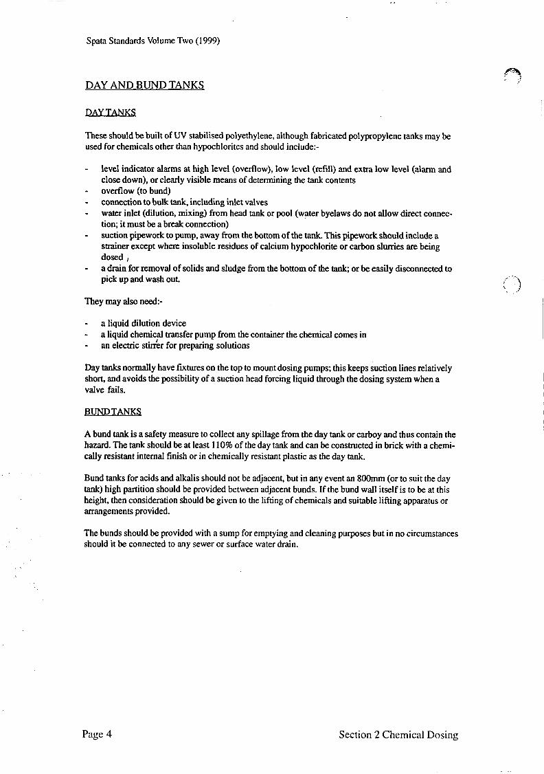
DAY AND BUND TANKS
These should be built of UV stabilised polyethylene, although fabricated polypropylene tanks may be used for chemicals other than hypochlorites and should include:-
-
- ovefflow (to bund) - -
level indicator alarms at high level (overflow), low level (refill) and extra low level (alann and close down), or clearly visible means of determining the tank contents
connection to bulk tank, including inlet valves water inlet (dilution, mixing) from head tank or pool (water byelaws do not allow direct connec- tion; it must be a break connection) suction pipework to pump, away from the bottom of the tank. This pipework should include a strainer except where insoluble residues of calcium hypochlorite or carbon slurries are being
a drain for removal of solids and sludge from the bottom of the tank, or be easily disconnected to pick up and wash out.
- dosed j
_ . -
I ) . . They may also need:-
- a liquid dilution device - - a liquid chemical transfer pump from the container the chemical comes in
an electric s&r for preparing solutions
Day tanks normally have furtures on the top to mount dosing pumps; this keeps suction lines relatively short, and avoids the possibility of a suction head forcing liquid through the dosing system when a valve fails.
A bund tank is a safety measure to collect any spillage from the day tank or carboy and thus contain the hazard. The tank should be at least 110% of the day tank and can be constructed in brick with a chemi- cally resistant internal finish or in chemically resistant plastic as the day tank.
Bund tanks for acids and alkalis should not be adjacent, but in any event an 8OOmm (or to suit the day tank) high partition should be provided between adjacent bunds. If the bund wall itself is to be at this height, then consideration should be given to the lifting of chemicals and suitable lifting apparatus or arrangements provided.
The bunds should be provided with a sump for emptying and cleaning purposes but in no circumstances should it be connected to any sewer or surface water drain.
Page 4 Section 2 Chemical Dosing
Spata Standards Volume Two (1999)
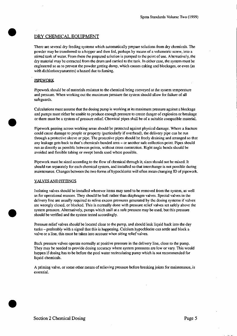
e DRY CHEMICAL EOUIPMENT
There are several dry feeding systems which automatically prepare solutions from dry chemicals. The powder may be transferred to a hopper and then fed, perhaps by means of a volumetric screw, into a stirred tank of water. From there the prepared solution is pumped to the point of use. Alternatively, the dry material may be extracted from the drum and carried to the tank. In either case, the system must be engineered so as to prevent the powder getting damp, which causes caking and blockages, or even (as with dichlorisocyanurates) a hazard due to fuming.
PIPEWORK
Pipework should be of materials resistant to the chemical being conveyed at the system temperature and pressure. When working out the maximum pressure the system should allow for failure of all safeguards.
Calculations must assume that the dosing pump is working at its maximum pressure against a blockage and pumps must either be unable to produce enough pressure to create danger of explosion or breakage or there must be a system of pressure relief. Chemical pipes shall be of a suitable compatible material.
Pipework passing across working areas should be protected against physical damage. Where a fracture could cause damage to people or property (particularly if overhead), the delivery pipe can be run through a protective sleeve or pipe. The protective pipes should be freely draining and arranged so that any leakage gets back to that’s chemicals bunded area - or another safe collection point. Pipes should run as directly as possible between points, without cross connection. Right angle bends should be avoided and flexible tubing or swept bends used where possible.
Pipework must be sized according to the flow of chemical through it; sizes should not be mixed. It should run separately for each chemical system, and installed so that interchange is not possible during maintenance. Changes between the two forms of hypochlorite will often mean changing ID of pipework.
VALVESAN D FI7TINGS
Isolating valves should be installed wherever items may need to be removed from the system, as well as for operational reasons. They should be ball rather than diaphragm valves. Special valves in the delivery line are usually required to relive excess pressures generated by the dosing systems if valves are wrongly closed, or blocked. This is normally done with pressure relief valves set safely above the system pressure. Alternatively, pumps which stall at a safe pressure may be used, but this pressure should be verified and the system tested accordingly. e Pressure relief valves should be located close to the pump, and should leak liquid back into the day tanks -preferably with a signal that this is happening. Calcium hypochlorite can settle and block a valve or a line, this must be taken into account when siting relief valves.
Back pressure valves operate normally at positive pressure in the delivery line, close to the pump. They may be needed to provide dosing accuracy where system pressures are low or vary. This would happen if dosing has to be before the pool water recirculating pump which is not recommended for liquid chemicals.
A priming valve, or some other means of relieving pressure before breaking joints for maintenance, is essential.
Section 2 Chemical Dosing Page 5

Spata Standards Volume Two (1999)
INJECTION FITTINGS
These connect the delivery line to the pool water recirculation pipework. Dosing points should be:-
- easily accessible for maintenance - - at least ten pipe diameters from any other dosing or sampling points
located where any slight leakage from one does not drip on to a lower one, or any other critical component, causing corrosion and subsequent failure.
All injection fittings should incorporate a non return valve to prevent pool water from entering the chemical dosing system - particularly when the plant is shut down. Injection points can be fitted with a stayclean assembly which enables the operator to rod through them to clear blockages.
OPERATION
Written procedures are essential for day tank filling, mixing or diluting chemicals and cleaning injec- tors etc. There must also be built in safeguards to cover those periods when the plant is not attended. Operational procedures should include a general survey to make sure the whole system is operating satisfactorily.
FAULTS
The system must fail safe if a fault develops: the system shuts down and an alarm sounds. There is little danger in turning off the treatment system for a short period to investigate a problem, as long as there are adequate reserves of disinfectant in the pool water.
Any disruption to the pool circulation must interrupt chemical treatment to prevent chemical build up in the system - which could gas pool users when circulation restarts. (The gas is chlorine, formed by the combination of disinfectant and acid dosed into the water confined in the pipe).
If the dosing plant is water operated, the water should come from the pool system and it too would fail safe with the circulation failure. Equally, dosing pumps regulated by a water flow meter signal offer a simple fail safe system. Otherwise there must be at least an electrical interconnection between the main recirculation pump, motor starter and the dosing system so that the dosing stops on motor failure. But this is best supplemented by pressure or flow sensors (which themselves fail safe), closing the system down when the main water system loses pressure or flow. This will overcome problems of loss of main recirculation pump prime, even when the motor runs.
During shut down periods of more than a few days, valves in filling lines between the day and bulk tanks should not be closed, as decomposition products from trapped hypochlorite may build up pres- sure. After such a shut down, the whole of the dosing system should be flushed through gently with low pressure water.
Page 6 Section 2 Chemical Dosing

Spata Standards Volume Two ( I 999)
COMMISSIONING
Commissioning should be done by trained and experienced engineers from the manufacturer or contrac- tor. Electrical tests must be conducted so that the system can be commissioned to Institute of Electrical Engineers (IEE) regulations. The commissioning details should be set down, and added to the written instructions in the manuals. The whole system should first be tested on water, ensuring that:
- - - pumps are calibrated - - -
there are no leaks under test pressure relief valves do relieve at the correct pressure and in the correct direction
pressure peaks do not exceed the maximum specified operating pressure all parts are secure and there is no vibration suction and delivery pipework is securely fixed, with no mechanical stress to fixed parts (eg pump discharge is best connected to rigid delivery pipe by means of flexible pipe).
The system can then be commissioned running with chemicals, looking at the same points until tests indicate satisfdctory performance.
I
AUToMATIC CONTROL
The chemical treatment of pool water is best automated for both disinfectant and pH control. Such controllers will optimise chemical treatment in the face of variations in bathing load, pool activity, even sunshine on the pool. Automatic systems do not. however, replace human operators (though they may give an alarm when a manual chore, like fdliog a tank. has been missed). They require proper calibration when fust skt up and regularly the&r. In particular, the choice of sample points is critical.
DOSING FEEDERS
Dosing feeders are available as either erosion feeders where water flow erodes a dry tablet chemical (generally one of the different chlorine compounds) or as soaker feeders which dissolve the material (generally bromine). Generally use is restricted to sanitisers although pH dosing can involve a feeder.
It is extremely important to ensure chemicals added to a feeder are never mixed. The feeder should be dedicated to the particular chemical material in use. As a safety measure, manufacturers recommenda- tions must be observed when selecting a suitable feeder for a particular chemical.
FTLTRATION INCOMP ATIBILW
In no circumstances should any flocculating agent, or algaecide, which contains any such flocculating agent, be used in conjunction with diatomite filtration. Further, no hypochlorite solution, which has an additive for softening water which in itself is a flocculating agent, shall be used with pre-coat filtra- tion.
In no circumstances should Treatment by electrolysis using the silver/ion exchange method be used in conjunction with pre-coat filtration.
Note -See Volume 3 for comprehensive detail on types of dosing and equipment.
Scctiori 2 Chcriiicnl Dosiris Page 7

Spata Standards Volume Two (1999)
I I
I I
Spata Standards Volume Two (1999)
SECTION 3
HEATING AND
ENVIRONMENTAL
CONTROL
Including
OUTDOOR SWIMMING POOLS
INDOOR SWIMMING POOLS

~~ ~
Spata Standards Volume Two (1999)

Spata Standards Volume Two (1 999)
a SECTION 3 -HEATING AND ENVIRONMENTAL CONTROL
POOL WATER TEMPERATURES
Swimmers are nowadays requiring higher water temperatures than ever before. Obviously temperatures should be maintained at a level to suit the optimum amount of pool users. Therefore it is important to establish client requirements at design stage.
28°C - 30°C (82°F - 86 OF) appears to be the most common requirement.
Small children, non swimmers and the disabled may find benefit with the higher temperature whereas training pools may prefer the lower end of the scale.
It is well to bear in mind that chlorine is used rapidly to cope with the increase in micro organisms caused by the heat and thus chemical costs will rise proportionately, as will energy costs, air tempera- ture and humidity.
Temperatures of 38°C - 40°C (100°F - 104°F) are too high for immersion in excess of 10 minutes and temperatures of 10°C and below likewise restrict usage to 10 minutes. a In all cases of extreme temperatures, swimmers or users should have medical clearance before using the pool. Alcohol should be avoided. The pool hall should be maintained at 1°C above the water temperature.
OUTDOOR SWIMMING POOLS
DESIGN CONSIDERATIONS
It is generally accepted that outdoor pools built within the U.K. will require a form of heat input in order for the pool water to be maintained at a comfortable temperature throughout the anticipated swimming season.
It is important to establish clients expectations of temperature and swimming season before offering a specific heating system.
Any chosen system must be compatible with swimming pool water and installed to manufacturers instructions and relevant standards.
a HEAT LOSS
The heat loss for any given pool will depend on the following:-
1. 2. 3. 4.
5. 6. 7. 8. 9.
a 10.
Volume of the pool, depth and surface area Required pool temperature Mean ambient air temperature of the coldest moth of usage Hours per day of operation of the heater - dependant upon the normal hours of use of the filter pump and, in the case of electric heaters, the number of hours that off peak electricity is available The time specified to heat the pool from cold in the coldest month The period for which a pool water surface cover is in use and its type Inground or above ground pool Effect of a water table (moving or static) and inadequate drainage around the pool Use of fountain or weir. (These should not be used if economic heating is required. The heat losses from this source could, in certain circumstances, exceed the rating of the heater) Degree of site exposure PREVAILING WIND DIRECTION ETC.
Section 3 Heating and Dehumidification Page 1

Spata Standards Volume Two (1999)
The use of pool covers is of considerable help in reducing running costs.
HEATING EOUIPMENT
There are five commonly used systems to provide outdoor pool heating. Each system has differing characteristics, installation requirements and sizing methods.
FUEL FIRED HEATERS
Gas heaters fall into two categories, specialist (direct) swimming pool heaters where the pool water flows through the boiler and central heating boilers (indirect) which are connected to the pool water via a secondary heat exchanger. Gas boilers should only be installedservices by registered Corgi installers. Direct boilers are normally supplied with thermostatic control. Indirect boilers will require a control scheme to be designed for the specific site requirements. As a minimum this will include a pool water temperature sensor to control the boiler/primary water flow.
Gas boilers should be connected to the pool filtration circuit via breakable thermal couplings with the following considerations.
1. Correct pool water flow 2. 3.
4. 5. 6.
A flow switch to stop the boiler in the event of low pool water flow If an automatic chemical feeder is used, installed within the system such that concentrated pool chemicals cannot enter the boilers heat exchanger. Be installed with service access in mind. Be provided with isolating valves and a bypass for servicing. Be installed for convenient winterising.
If boilers are sited in a plant room, the room must be ventilated to manufacturers recommendations. The plant room should also comply to Corgihuilding regulations for rooms containing boilers.
As with gas heaters, oil fired heaters are available in either direct or indirect configuration. The design considerations mentioned in (i) are relevant to oil boilers. Specific appliance installation needs should be referred to the manufacturers installatiodservicing instructions. In the event that an existing house heating system is linked to a pool heat exchanger, priority should be given to the house heatinghot water. It is also important to establish that the existing heater is compatible with the pool heating load.
FUEL FIRED HEATING SIZING
Fuel fired heaters are normally sized to heat pool water from cold to design temperature in 60 hours, assuming no losses. A guide to typical mean monthly unheated pool water temperature is shown in table (1).
Month J F M A P J J A OC 3.8 3.8 5.7 7.9 11.2 14.1 16.1 15.8 OF 38.8 38.8 42.3 46.2 52.2 57.4 61.0 60.4
Month S O N D OC 13.6 10.6 6.5 4.6 O F 56.5 51.1 43.7 40.3
Page 2 Section 3 Heating and Dehumidification
Spata Standards Volume Two (1 999)
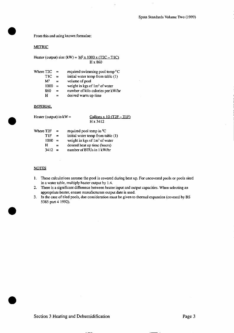
From this and using known formulae;
Heater (output) size (kW) = Mix 1000 x (T2C - TlCl H x 860
Where T2C = required swimming pool temp OC TIC = initial water temp from table (1) M3 = volumeofpool 1000 = weight in kgs of lm3 of water 860 = number of kilo calories per kWhr H = desired warmuptime
IMPERIAL
Heater (output) in kW = Gallons x 10 (T2F - TlFl H x 3412
Where T2F = required pool temp in OC T lF = initial water temp from table (1) 1000 = weight in kgs of lm3 of water H = desired heat up time (hours) 3412 = number of BTUs in 1 kWhr
NOTES
1.
2.
3.
These calculations assume the pool is covered during heat up. For uncovered pools or pools sited in a water table, multiply heater output by 1.4. There is a significant difference between heater input and output capacities. When selecting an appropriate heater, ensure manufacturers output date is used. In the case of tiled pools, due consideration must be given to thermal expansion (covered by BS 5385 part 4 1992).
Section 3 Heating and Dehumidification Page 3
Spata Standards Volume Two (1999)
ELECTRIC HEATING
ELECTRICAL. RES ISTANCE HEATING
Electrical resistance heaters are normally of the direct type encompassing a heater element which is compatible with swimming pool water. Installation into a pool filtration circuit carries the same considerations as fuel fired heaters.
It is important that the proposed site has an adequate electrical supply to cater for the heater and due consideration is given to cable sizing between main supply and plant room. All electric heaters must be installed in accordance with current I.E.E. regulations.
ELECTRICAL RESISTANCE HEATER SIZING
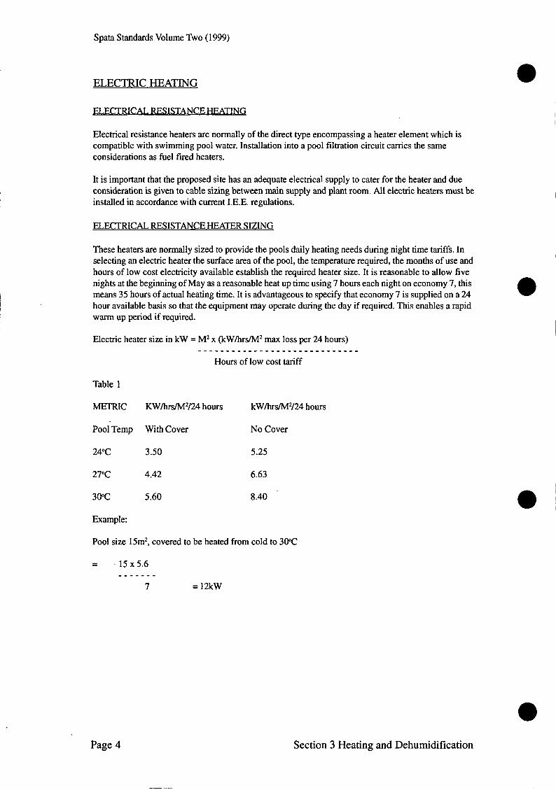
These heaters are normally sized to provide the pools daily heating needs during night time tariffs. In selecting an electric heater the surface area of the pool, the temperature required, the months of use and hours of low cost electricity available establish the required heater size. It is reasonable to allow five nights at the beginning of May as a reasonable heat up time using 7 hours each night on economy 7, this means 35 hours of actual heating time. It is advantageous to specify that economy 7 is supplied on a 24 hour available basis so that the equipment may operate during the day if required. This enables a rapid warm up period if required.
Electric heater size in kW = M2 x (kW/hrs/M2 max loss per 24 hours) . . . . . . . . . . . . . . . . . . . . . . . . . . . . .
Hours of low cost tariff
Table 1
METRIC KW/hrs/M2/24 hours kW/hrs/M2/24 hours
Pool Temp With Cover No Cover
24°C 3.50 5.25
27°C 4.42 6.63
30°C 5.60 8.40
Example:
Pool size 15m2, covered to be heated from cold to 30°C
= . 15 x 5.6 _ _ _ _ - _ -
7 = 12kW
Page 4 Section 3 Heating and Dehumidification
Spata Standards Volume Two (1999)
0 HEAT PUMPS
Heat pumps are usually electrically driven but differ from other dynamic heating devices by providing most of their heat output from energy they have recovered from a low grade source such as outside air. For an average summer season, the ratio of heat output to electricity consumed is approximately 4:l. Installation considerations are as electric flow heaters. Consideration for air flow through the heat pump must be taken into account. If installed within a plant room, the room should be ventilated and air discharged from the heat pump should be rejected directly outside. The heat pump will also require a condensate drain to waste. Heat pumps are often sited outside. Under these circumstances they should not be sited such that air which is drawn through them can recirculate.
HEAT PUMP SIZING
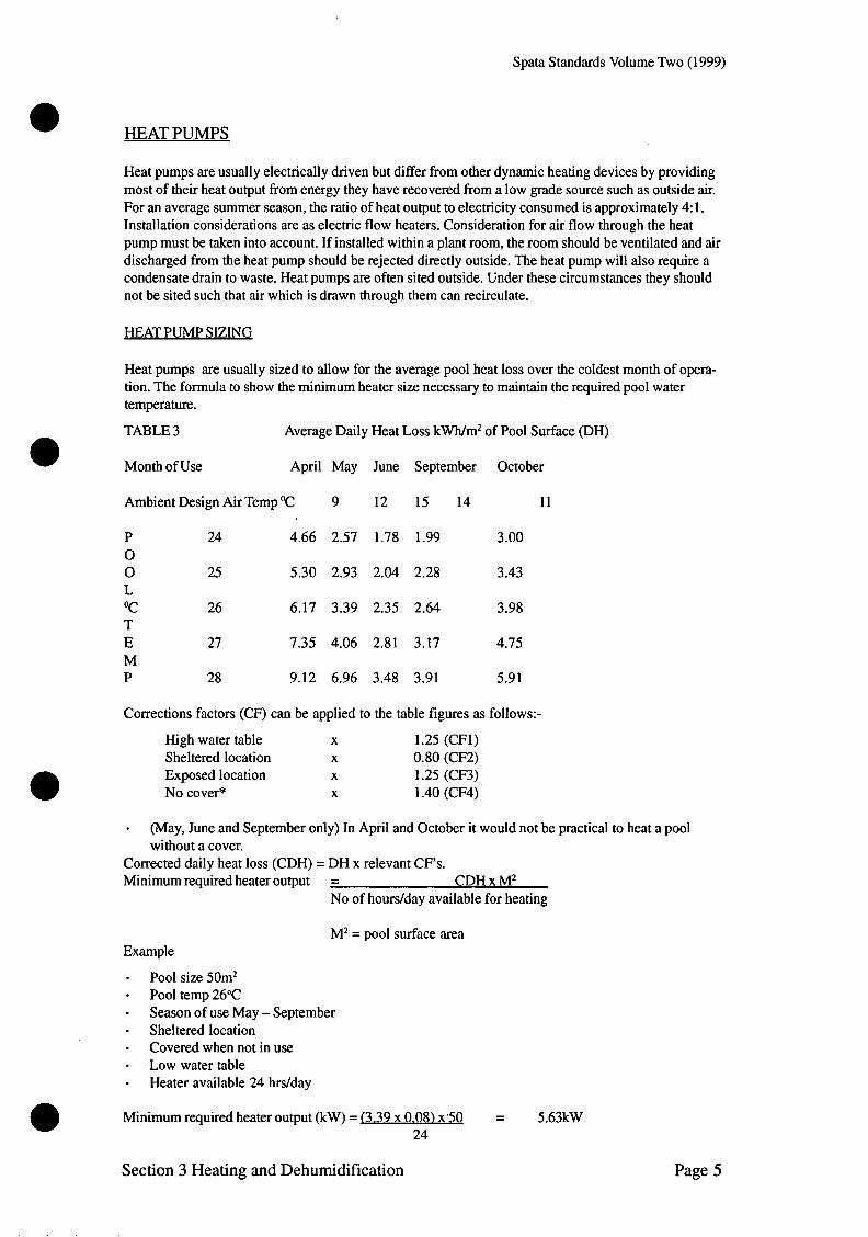
Heat pumps are usually sized to allow for the average pool heat loss over the coldest month of opera- tion. The formula to show the minimum heater size necessary to maintain the required pool water temperature.
TABLE 3
0 Month of Use
Average Daily Heat Loss kWh/m2 of Pool Surface (DH)
April May June September October
AmbientDesign AirTempOC 9 12 15 14 11
P 24 4.66 2.57 1.78 1.99 3.00 0 0 25 5.30 2.93 2.04 2.28 3.43 L OC 26 6.17 3.39 2.35 2.64 3.98 T E 27 7.35 4.06 2.81 3.17 4.75 M P 28 9.12 6.96 3.48 3.91 5.91
Corrections factors (CF) can be applied to the table figures as follows:-
High water table X 1.25 (CF1) Sheltered location X 0.80 (CF2) Exposed location X 1.25 (CF3) No cover* X 1.40 (CF4)
- Corrected daily heat loss (CDH) = DH x relevant CF’s. Minimum required heater output = CDH x M2
(May, June and September only) In April and October it would not be practical to heat a pool without a cover.
No of hours/day available for heating
M2 = pool surface area Example
- Pool size 50m2 - Pool temp 26°C - Season of use May - September - Sheltered location - Covered when not in use - . Low water table * Heater available 24 hrs/day
Minimum required heater output (kW) = 13.39 x 0.08) x.50 = 5.63kW 24
Section 3 Heating and Dehumidification Page 5

Spata Standards Volume Two (1999)
SOLAR HEATING
NOTE - Solar heating systems for swimming pools is fully described by BS 6785:1986
A solar heating system will provide a means of passively heating pool water by harnessing energy from the sun. Solar collectors are connected to the pool filtration circuit (fig 2 & 3 ) such that water flowing through them is heated as a result of their ability to absorb energy from the sun. Solar heating systems fall into 'direct' and indirect categories. In both cases a control system must be used, preferably automatic. It is important to understand that the control of solar heating systems is more complex than other systems and should be designed such that; the collectors will not act as emitters. It is advisable to consult with the collector manufacturer before choosing a suitable means of control.
STING
The siting position of collectors is critical to their performance. For maximum output they should be sited in a sheltered area facing between 30" east and 40" west of the south. They should be inclined from the horizontal between 20" and 50 O.
It should be noted that planning permission may be required and that installations should take into account wind and snow loadings.
SIZING
It is virtually impossible to practically calculate the size of the panel needed to maintain a specific pool temperature. It is generally accepted that the following factors will provide a comfortable tem- perature between May and September providing a pool cover is used.
Location Ratio of collector area to pool area
S he1 tered 0.5
Exposed 0.8
Should it be deemed necessary to hold constant pool temperatures throughout the swimming season. It is advisable to fit an auxiliary form of heating, controlled to operate during times when the solar heating cannot maintain conditions.
Page 6 Section 3 Heating and Dehumidification

1.
2.
3.
4.
5.
6.
a 7. 8.
9.
Spata Standards Volume Two (1999)
GENERAL HEATING CONSIDERATIONS
Heating systems should be installed such that they do not restrict the pool water flow below design turnover rates. If necessary an auxiliary pump should be fitted. Due consideration must be given to winterisation by fitting breakable couplings to disconnect the heating during the winter. Alternatively frost stats should be fitted to ensure water is constantly passing through the heater when outside temperatures fall below 3 "C. If this method is adopted, it is important to ensure that the pool water chemical balance is maintained throughout the winter. Boilers and electric flow heaters should be fitted with a suitable pressure valve set at 2.1kg/cm2 (3Opsi). Thermostats used to sense pool temperature for the purposes of controlling a heater should have a maximum differential of 1 "C. Wherever possible heaters should be positioned as close as practical to the pool filtration equip- ment. However this should not compromise noise, heater efficiency and accessibility. In the event that a heater is below the level of the pool,
a) isolating valves must be fitted such that maintenance can be carried out without draining the pool.
b) If in a plant room, a submersible pump capable of delivering water at a rate equal to the full bore flow of the main pump must be fitted.
Where a heater is connected to flexible pipes, the heater must be f d y fixed to a solid foundation. Pool chemicals must not be stored in the same space as a conventional flue boiler. Due considera- tions must be given to the corrosive and toxic nature of chemicals such that controls, heaters and other associated components are not affected by chemical vapours. Heaters must not be run until fully commissioned in accordance with manufacturers instructions.
Section 3 Heating and Dehumidification
~~~ ~~~~~~ ~~~~~~~
Page 7

Spata Standards Volume Two (1999)
INDOOR POOL HEATING AND ENVIRONMENTAL CONTROL
DESIGN CONSIDERATIONS
Indoor pools contained within a permanent structure provide the design engineer with many factors to consider before selecting suitable systems. The basis of any system design should address; water heating, space temperature control, humidity control and fresh air dilution. It is important to understand that swimming pool halls represent a greater challenge to heating engineers and architects than nor- mally controlled spaces and consequently choice of building materials, their method of application and general architectural design will play an important role in the overall effectiveness of an indoor pool environmental control system.
POOL WATER HEATING
Outdoor pool heating methods and sizing guides apply to indoor pools, although it is important to realise that temperature expectations of indoor pools is generally higher and in the case of spa pools or special needs pools (hydrotherapy), temperatures may be as high as 36 "C. Indoor pool water heating is often supplemented by a heat recovery system which rejects by-products of dehumidification back to the pool water as sensible heat. Under these circumstances primary pool heating sizes remain unaf- fected but thermostatic control should be set such that the heat recovery system has 1 "C higher set point in order to fully utilise its effect in reducing pool water heating costs.
In the event that space heating is provided by a common boiler, the boiler should be sized such that water and air heating can be provided simultaneously.
For the comfort of bathers and lower evaporation of moisture from the pool, space temperatures should generally be 1 "C higher than the pool temperature. If a pool cover is used, the space temperature may be set back to 22 "C when in place.
In the case of hydrotherapy and spa pools where such high air temperatures may not prove feasible, higher dehumidification loads should be expected. Space heating capacities are calculated using conventional heat loss/gain calculations, however it is important to take into account ventilation losses, which with certain types of environmental control systems may be significant.
SPACE COOLING
Pool halls with large glazed areas facing south and/or high occupancy rates may require cooling during warmer weather. This is normally affected by introducing controlled quantities of fresh air and/or mechanical cooling (air conditioning). Heat gain calculations will dictate precise quantities.
FRESH AIR
Other than for small domestic pools, controlled fresh air quantities should be considered in order to dilute COZ build up from people and prevent excessive airborne chemical levels. For design purposes 10 L/S of fresh air per person and 3 US/m of pool area should be considered. It is considered good design practice to incorporate a form of heat recovery such that the fresh air is preheated by exhausted stale air. When selecting dynamic fresh air rates, consideration to providing a slight negative pressure within the pool hall should be taken into account in order to prevent 'pool hall' air conditions from migrating to adjacent rooms and to reduce the possibility of airborne moisture being driven into the building fabric.
In the event that fresh air is used for excessive temperature control and or humidity control, substan- tially higher quantities of fresh air will be required. These quantities will be dictated by building design and equipment selection.
e
Page 8 Section 3 Heating and Dehumidification
Spata Standards Volume Two (1 999)
HUMIDlTY CONTROL
Humidity control within an indoor pool hall is necessary to provide a comfortable environment for occupants, prevent building fabric and humidity related damage to materials within the space. Humidity control will also assist condensation control on cold surfaces such as glass, providing a suitable air distribution system is employed. Humidity levels for a typical indoor pool enclosure should be main- tained at 55 - 65% RH, although levels as low as 40% may be considered acceptable during unoccu- pied periods when natural infiltration of cold outside air may balance the hall at this point.
Humidity control may be effected by utilising various methods;
The traditional method of humidity control is to preheat fresh air which is swept through the pool hall and then rejected back to outside after absorbing moisture from the pool hall air. Typically this method will require 7 air changes per hour. The system is energy inefficient due to the high volumes of heated air which are thrown away, although may prove suitable for use in pool halls which are used only in moderate weather. In order to improve the energy efficiency of a fresh air system, a plate heat ex- changer should be considered. These units will recover up to 70% of the rejected sensible heat but are not capable of recovering significant quantities of latent heat. If a recuperator is used, automatic bypass provisions should be provided in order for it to provide cooler air during warm weather. Fresh air systems are usually connected to an air distribution system.
a HEAT PUMP DEHUMI DIFICATION
Heat pump dehumidifiers recirculated pool hall air removing moisture from it as it passes through the machine. Good design dictates that they should turn over the air at least three times per hour. These systems dramatically reduce ventilation losses by predominantly recirculating, rather than discharging heated air. Heat pump dehumidifiers are capable of providing water and space heating by converting reclaimed latent energy to sensible heat. Under these circumstances, space and water heating needs should be calculated by sizing primary heat exchangers to give 100% of the required duty. More sophisticated heat pump dehumidifiers will provide fresh air needs and summer time cooling. It is important to consider these factors when sizing machines. As a heat pump dehumidification system may provide all of the necessary environmental control parameters, sizing and equipment selection should be verified by the supplier.
Section 3 Heating and Dehumidification Page 9

Spata Standards Volume Two (1999)
Page 10 Section 3 Heating and Dehumidification
Spata Standards Volume Two (1 999)
CONDENSATION CONTROL
L
There are three main considerations in the prevention or minimising of condensation.
2.
z
Good Buildinp Des ig
- High insulation values - - - - - -
Double glazing - triple glazing or low E glass preferred Avoid roof lights if possible Where possible windows should be flush with inner surface Glazed frames should contain a thermal break Avoid cold bridging by structural members Incorporate suitable vapour barriers where appropriate (polythene is not generally considered adequate for a corrosive atmosphere).
Keep air moving across potentially cold surfaces
Air moving at a sufficient rate will not be in contact with the surface long enough for it to cool to its dewpoint.
Maintain ideal relative humidity (55% - 65%)
INSTALLATION NOTES
NON DUCTED SYSTEMS
For smaller pool halls where a central ducted system may not be incorporated;
Standard domestic radiators should not be used as their pattern of heat convection from low level is not beneficial for an indoor pool. In addition, when considering that the pool hall floor may be wet and slippery, they also represent a potential safety hazard. Warm air blowers are preferable and far more suitable for the application. Equally a warm air heating coil could be incorporated into most dehumidi- fiers. When using dehumidifiers or other electrical devices within the pool hall;
1.
2.
AIR DISTRIBUTION. DUCTWORK AND GRLLES
Ensure they are intended for use in swimming pool hall environments. Items not intended for such use will infringe IEE regulations. Ensure the positioning of any electrical devices is in accordance with IEE regulations.
Air distribution systems are installed to ensure even distribution and consequently uniform air tempera- ture and humidity throughout the conditioned space.
The air distribution scheme should be designed to ensure a curtain of conditioned air encompasses all area of potential dewpoint condensation such as windows.
Section 3 Heating and Dehumidification Page 11

.
Spata Standards Volume Two (1999)
SYSTEM DESIGN
The methods by which air may be distributed around the indoor pool enclosure are numerous, but generally fall into one of the following categories:-
Single point supply Concealed distributed, underground Concealed distributed, overhead Exposed, overhead
Single point supply comprises a single grille attempting to throw the entire air volume into the enclo- sure. This is likely to be completely successful only on very small pools, or pool enclosure that include either no external glass, or high specification insulated glass.
Concealed distributed, underground schemes required co-ordination with the swimming pool pipework, building foundations and floor structure. Particular care is required to achieve a successful scheme where for instance beam and block flooring is to be used.
Grilles could be floor or window sill mounted of a fixed reinforced blade design to withstand weight of bathers.
Concealed distributed, overhead ductwork can be sub-divided into:-
1.
2.
Ductwork run in a false ceiling void, with grille openings piercing the ceiling finish and the main duct connected to the grille above the false ceiling. Bulkhead style systems where the duct is below the main ceiling line, but is concealed by being boxed in using building materials
Grilles would be of an adjustable design to allow for direction of air flow as desired.
Exposed, overhead schemes are generally run along the building centre line, although perimeter systems can provide an attractive alternative on larger buildings. Surface coatings need to be carefully chosen to provide protection against corrosion. Grilles would be mounted on the side of these ducts generally facing the required direction. Adjustment of the grille should be allowed to provide adequate air throw and direction.
DETAILED CONSTRUCTIONAL SPFEIFICATION
The standard to which the ductwork is manufactured is covered by the Heating and Ventilation Contrac- tors Association document DW 142 Specification for sheet metal ductwork.
This document covers matters such as thickness of materials to be used, varying with the duct size, and methods by which the sheet metal should be jointed. The standard also details maximum distances between supports. The recommendations of this standard should be adhered to, with the exception of the additional thickness recommended in this standard for underground ductwork.
Page 12 Section 3 Heating and Dehumidification
Spata Standards Volume Two (1 999)
a DETAILED DESIGN CONSIDERATIONS
The methods by which air flows, pressure drops, and duct sizes are calculated are covered in detail by the standards of The Chartered Institute of Building Services Engineers (CIBSE). These however follow the conventions of the building services industry whereby the output of the fan in the air han- dling system may be chosen to suit the ductwork scheme. It is possible that the air handling unit used for the dehumidification of an indoor pool will have very few options in terms of fan output, and the ductwork system may therefore need to be designed to dissipate excess fan pressure.
In general the following guidelines may be adopted as the initial design basis.
Maximum duct velocity 5.5 m/s (where outlet grilles are within 3 metres of duct) Maximum duct velocity 7.5 m/s (where outlet grilles are in excess of 5 metres) Maximum return air grille velocity 2.3 m/s Maximum weather louvre velocity 2.5 m/s Maximum floor grille velocity 1.5 m/s Maximum floor grille velocity 0.5 m/s Maximum double deflection grille velocity 2.5 m/s (unless special circumstances) Maximum velocity in grille spigot 2.5 m/s
Manufacturers of air grilles produce selection tables detailing noise levels, air throw distances and pressure drops. These tables should be consulted to achieve the desired performance from the system.
a It should be noted that a system which employs initially the maximum duct velocity, with reducing velocities approaching the final grille, will be more simple to balance at the commissioning stage due to an element of static regain.
These figures should be applied to the initial flow schematic, and pressure drop calculations performed to ensure that the installed fan options and adequate. An allowance should be made at this stage for increased system pressure losses when air filters become dirty.
The design of the ductwork shall rely upon air flow figures and pressure drops as provided by the supplier of the air handling system, or air handling specialist.
All systems should include a main duct damper for the regulation of total air flow. The individual grille dampers are not normally suitable for major air flow regulation.
DETAILED CONSTRUCTIONAL REOUIREMENTS
DISTRIBUTED UNDERGROUND
The use of an underground ductwork system should only be considered once the natural ground water level is determined. The water tables current and previous levels should be well below the lowest part of the duct. Water ingress into the duct scheme will hinder air flow. Added water will increase dehu- midification costs, and heating costs. The water introduced may, at the extreme, completely undermine the performance of the system.
Where a high water table exists, and no other acceptable location for the duct is possible, then ground water drainage, or a water proof duct system should be considered. Any water proofing should how- ever account for the action of the settlement, and potential cracks allowing water to re-appear.
Ground drainage at its simplest could take the form of an over excavated trench, fitted with a perforated land drain pipe covered in shingle. This would run to a suitable sump location where a pump fitted with a level switch would drain the duct trench whenever the water level was unacceptable.
Section 3 Heating and Dehumidification Page 13

Spata Standards Volume Two (1999)
Underground ductwork should be fabricated from suitable materials with proven long life, and prefer- ably a smooth finish surface. Galvanised mild steel ductwork, if used, should be fabricated to DW142 adopting a sheet thickness one gauge higher than recommended in that document. This is in respect of the weight of back fill material and likely rough handling in such a vulnerable location.
Flexible ductwork should not be used underground where it is to be back filled.
Plenum boxes for the air outlet grilles should be reinforced to resist loading from concrete. Reinforcing may include
1. Fabrication from 18 gauge steel 2. Angle stiffening to top edge 3. Internal bracing
Particular care should be taken to ensure that adequate bracing of the plenums is provided during pouring of oversite concrete and screeding.
Floor plenum boxes should be designed to promote even flow to all areas of the supply grilles. Side entry plenums are therefore to be preferred. Regular air supply plenums should be installed along the length of large grilles, once again to promote even air supply.
Ductwork which will be surrounded with back fill should also be reinforced with angle sections to resist the weight. Where flanged interconnection joints are used these can also be considered to act as this stiffening.
Inground ductwork should be insulated to minimise heat loss to the ground. Insulation should be formed from rigid board material, which is not capable of absorbing water from the surrounding earth. This would normally preclude the use of circular ductwork underground where flexible absorbent insulation would be necessary. The insulation should be protected during the construction stage with a resilient material to minimise damage and water and debris ingress during construction.
Floor grilles should be of a reinforced grade, suitable for accepting the weight of bathers without deflecting. Blades should not be adjustable therefore, but should be fixed, ideally at an angle facing the glass or other areas requiring direct air flow. Blades should be set out to prevent entrapment of toed fingers etc. A 6mm gap between 6mm wide blades would be seen as typical for an acceptable grille. Grilles should include an adjustment damper for the balancing of air flows between adjacent outlets.
Grilles may be recessed, below the tiling line, or raised, resting on the tiles. Raised grilles if necessary should feature bevelled corners to minimise accidental injury to bare feet.
A surface coating should be applied to reduce the risk of corrosion. Standard treatments such as polyester powder coating and stove enamelling would be suitable finishes, available in most colours to complement the interior design.
Floor grilles will ideally be the full length of the glazed opening.
Where a suspended beam and block floor is to be used, a co-ordinated design solution will be required with input from the floor designer and ductwork specialist. Access to the floor grilles may otherwise be obstructed by the support beams.
Where supporting calculations prove the requirement for attenuation, this should be placed in the plant room. Under ground attenuators are to be avoided.
Page 14 Section 3 Heating and Dehumidification

Spata Standards Volume Two (1999)
e DISTRIBUTED OVERHEAD
Overhead distribution ductwork may be formed in galvanised circular, oval or rectangular cross sections. The ductwork layout should be co-ordinated with the building designer to ensure the minimum impact on trussed roof designs, and to ensure that locations are available as required in ceilings etc. In particular centre line locations above external glass may be made available which will improve the appearance and system performance.
The installer shall ensure that support centres recommended by DW142 are adhered to, as are recom- mendations in respect of joint sealing and fixing.
Ductwork which is located above the main roof insulation shall be insulated to minimise heat loss to unheated areas. Insulation would typically include 40mm foil faced mineral wool, or fibreglass slabs or mattress. This should be securely attached to the ductwork using pins, banding or galvanised wire netting. Joints between adjacent sections of insulation should be made using wide foil self adhesive tape. The installer should be aware of the arduous nature of a warm humid pool hall and the additional requirements this places upon the ductwork insulation.
Where supporting calculation prove the use of attenuators is necessary, these should be placed as close to the plant room wall as possible, to prevent ‘flanking’ noise breaking into the ductwork after the attenuator.
Where flexible ductwork is to be used to connect from the main ducts to the grilles, this shall be kept to the minimum practical length. Where the duct location required insulation, then insulated flexible ductwork should be used. Flexible ductwork should not be used excessively.
Where an overhead distribution scheme is above the buildings general vapour barrier, then occasional openings may be required in the vapour barrier for the provision of air introduction into the room. Openings in the vapour barrier shall be repaired with the grille boxes sealed and fixed firmly to the barrier to ensure the barrier is not compromised.
Where ducting system are installed above the vapour barrier, then consideration shall be given to pressure testing the ductwork to prove air tightness. Pressure testing should be to DW143. When ducts run through non heated voids, condensation may occur and consideration should be given to addressing this.
Overhead ductwork schemes will require that supply grilles are located as close as possible to vulnerable areas of the building. Since ceiling joist locations will also need to be considered, it is likely that a grille offering two way adjustment will be most suitable. These double deflection grilles should have an adjustable damper for regulating air flow between adjacent outlets.
Grilles should be provided with a surface finish to protect against the pool atmospheres potentially corrosive nature. Polyester powder coating and stove enamelling are example finishes.
Overhead exposed systems may be constructed from rectangular, circular or oval duct forms. Surface protection should be provided in the form of polyester powder coating, stove enamelling or fabricating from plastic coated steel.
Support systems should be coated in the same manner as the ductwork, adopting the support centres, and material thickness quoted in DW 142.
Due to the often remote nature of over head schemes, air distribution, and grille throws shall be selected with care. Consideration shall be given to specialist drum jet or jet flow diffusers which offer long distances over which the air may be projected. Consideration should be given to the location of these grilles and where possible locating over the pool surface should be avoided to improve access for adjusting and cleaning.
Section 3 Heating and Dehumidification Page 15
Spata Standards Volume Two (1999)
,PLANT ROOM DUCTING
Plant room ductwork should be manufactured from galvanised sheet steel generally in accordance with DW142. Insulation should be as over head ductwork, 40mm foil faced mineral wool or glass fibre, wrapped in galvanised wire netting.
All ductwork connections onto air handling plant should include flexible sections which may be removed in the event of machine malfunction and replacement.
Ductwork design should not impair access to any item of plant nor restrict headroom unnecessarily.
Return air ductwork should be treated against corrosion by the use of a suitable painted treatment such as acrylated rubber paint. Where calculation prove the requirement, the return air section should include an attenuator.
As an alternative to return air ductwork providing a plenum chamber within which the equipment is sited maybe considered. 1. plenum chamber should not be used if either a naturally ventilated boiler is present within the
room 2. the room contains equipment sensitive to pool water sanitisers. 3. The room is used for storage of swimming pool chemicals or dosing equipment which exposes
chemicals to the air.
The return air duct, where extended due to layout limitations, should be sized to reduce suction pres- sures within the air handling plant. The system designer and plant manufacturer should be consulted with respect to a suitable pressure drop in this section of ductwork.
The fresh and stale air ductwork terminating at weather louvres should be designed to minimise water ingress under driving rain conditions.
This would typically involve reduced inlet velocities and designing the first section of ductwork sloping towards the wall so that any water introduced runs back to outside.
External louvres should be finished with a corrosion resistant coating such as stove enamelling or polyester powder coating.
HEALTHANDSAFETY
When designing, due attention should be taken to Health and Safety matters with particular regard to:-
- -
noise attenuation where plant is sited close to the pool or other occupied premises the use of specialised fire grilles in fire doors
The completed scheme should be balanced and commissioned in accordance with the intended design air flows. A commissioning sheet should be presented with the appropriate figures with the handing over certificate.
Page 16 Section 3 Heating and Dehumidification

Spata Standards Volume Two (1999)
SECTION 4
COVERS AND
AIR ENCLOSURES

~~ ~
Spata Standards Volume Two (1999)

Spata Standards Volume Two (1999)
SECTION 4 - COVERS AND AIR ENCLOSURES
WINTER COVERS
Covers used on outdoor pools during winter when the pool is no longer in use. Fixings are semi- permanent and not designed for daily usage. This type of cover should minimise the amount of dirt and debris getting into the pool but can only offer a minimal degree of safety providing it has been fitted and maintained correctly. It is not designed as a safety cover and under no circumstances should children, animals or pets be allowed to walk on the cover. There are two main types as follows.
OPEN MESH POROUS) DEBRIS COVERS
These covers should be of a closely woven polyethylene fabric with maximum ultra light inhibitors and should allow rain to pass through when suspended across the pool deck. The cover should be tailored to the shape of the pool with an additional allowance of not less than 30Omm all round. Seams and fixing straps should be tailored using strong UV resistant thread and fixing straps should be secured at intervals of no more than 1 Sm(5') by firmly secured pegs into the pool surround. Tension should be maintained by the use of locking buckles and or stainless steel springs. Fixing hardware should be made from non corrosive material with spring and pin fixings of high grade stainless steel and screw or pop up anchors of brass or similar. Fixing straps should be manufactured from high strength webbing which includes UV inhibitors and should be a minimum of 3Omm wide. Straps should be evenly positioned at centres of a maximum of 150Omm on straight sides and lOOOmm on curved corners. Protection to the underside and vulnerable areas (Roman Ends, Walk in Step sections) should be provided by an anti chaffing strip.
a
COATED MESH (NON POROUS) DEBRIS COVERS
These covers should be made from non porous reinforced PVC or similar fabric. This type of cover is not designed to be tensioned across the pool but should instead be allowed to lay on the water surface and secured with either sand or water bags which are positioned around the edge of the cover. Covers of this type should be made with an overlap of not less than 60Omm all round. A seepage or filter panel may be fitted to the cover to allow rain water to penetrate into the pool, but if no such panel is fitted all rain water and debris must be removed before the cover is taken off. A small submersible pump (not necessarily supplied) should be used for this purpose.
Where steps are removable the cover should be made with no cutouts. Where the steps are fixed, detailed measurements should be given to the manufacturer to obtain as good and close a fit as possible at step cut outs.
a Buckles must be of a non slip adjustable type. The claw type buckle, or buckles that have sharp teeth, should not be used as they can damage the strappings.
SOLAR BLANKETS (BUBBLE COVERS)
Generally of polyethylene extrusion with individual air cells which heat up when exposed to solar energy. This heat is transferred into the pool by placing the cover bubble side down to maximise the surface area in contact with the water. The cover also seals the pool surface almost eliminating heat and chemical loss through evaporation. Various thicknesses of material with a choice of edge finish are available. Suitable material should include maximum ultra violet light inhibitors and be compatible to water temperatures between 15 and 28"c and normal level of pool temperature chemicals. 400 micron grade is considered to be the most durable and sufficiently robust to provide for a minimum 3-4 years of continued use.
Section 4 Covers and Air Enclosures Page 1

Spata Standards Volume Two (1999)
HEAT RETENTION COVERS
These can be of PE foam laminated (5mm - 8mm) or flame bonded foam (2mm- 3mm). Bubble covers can also be included in this category. They are specifically designed to give the maximum insulation to the surface of the pool when not in use and enable the pool to be maintained at the required temperature with the minimum of heat loss. The cover should cover as much of the surface area as possible whilst still being able to be removed and stored, preferably in a roll, with the minimum of effort. The tempera- ture that the pool is run at should be matched to the cover type.
Indoor private pools which generally have limited usage meaning that they would not benefit from solar gain. Covers used in instances should have a minimum of 3mm closed cell foam bonded to top and bottom sheets for strength.
MANUAL POOL COVER ROLLERS
A manual pool cover roller is designed to simplify the removal of the floating cover. Used comctly it will prolong the life of the cover. The barrel of the roller should be made from extruded aluminium with a minimum wall thickness of 2mm and a minimum diameter of 6Omm o/d. The barrel may be in one section or as a telescopic format. Telescopic versions should include a minimum of 30Omm overlap between the sections when the barrel is extended to its maximum. The unladen barrel should not show any signs of sagging. When the cover is fully wound on to the barrel slight sagging is consid- ered possible but this should not increase the overall winding diameter by more than 40% and should not affect the operation of the equipment. The support brackets can be made from any form of non corrosive material such as a high grade of stainless steel, or mild steel providing that is corrosive protected and plastic coated. Toughened moulded plastic may also be used. The winding mechanism should be of a crank handle or steering wheel type which should be attached to the barrel to provide ease of movement (without cover). Where the equipment is of a mobile design some form of anchoring should be supplied, this may consist of locking castors but these must hold the equipment in a stable position whilst the cover is being wound on.
CARE AND MAINTENANCE
The covers should be regularly maintained and care should be exercised when handling and storing them. The following points should be observed to ensure good service:-
1. 2.
3. 4.
5.
6.
7. 8.
9.
When ordering the cover, check all pool measurements to ensure a good fit Keep the cover in a shed or outhouse so that it is protected from sunlight as this has a degrading effect on all synthetic materials Keep the cover away from hot water pipes, heaters and fires. Excessive heat will cause damage Keep the cover away from bonfires and fireworks as sparks or burning debris can burn holes in the material Keep the cover taut at all times, except when there is heavy snow, when the cover should be allowed to rest on the water to prevent damage to the cover and springs Do not allow the cover to lie in the water, as leaves and debris will collect, decompose and filter into the pool water Maintain the water level in accordance with the winterisation instructions for the pool Ensure that the flush deck anchors are well greased at all times to prevent grit and dirt from being washed down in the moving parts. Ensure that all parts move freely When fitting the cover, ensure that the anti chafing strips face the pool water and are not on top of the cover
10. Do not allow children to play on the cover 11. Do not drag the cover over rough ground. Always fold it up and carry it away. This will prevent
12. Care should be taken to prevent damage by animals. Horses, cattle and other animals have been damage by snagging and abrasion
known to stray onto a pool cover, causing damage both to the cover and themselves. The remedy is to maintain fences and hedges in good order.
Page 2 Section 4 Covers and Air Enclosures

These covers should be fitted with
drain holes or an electrically safe pumping system to remove any surface water completely.

Spata Standards Volume Two (1999)
AUTOMATIC AND MOTORISED COVERS
These covers are devised to facilitate a simple fitting and removal of swimming pool covers and generally consist of a mechanically operated roller or reel together with a floating cover. Reels are generally fitted either just below or just above the water level although other positions may be used according to specific requirement.
There are, currently, two basic types of mechanically operated reels:-
1.
2.
Electrically operated where the shaft is turned by an electric motor, either fitted within the shaft or mounted externally on a spindle or chain drive. Hydraulically operated where the shaft is turned by a pumped flow of fluid using the Archimedian screw principle.
I
The operation of both is controlled by elecmc or electronic signal from which a switch position to a control point.
COVE R MATE RIALS
Slatted covers comprise a number of extrusions, which interlock together. In order to roll up each slat is usually in the order pf 5Omm in width. Each extrusion is capped at either end allowing floatation. They are pushed and pulled across the water surface by the motor.
Solar slats are made from a material, which attracts solar gain and as a result must be handled with care when fitting. If left in the sun, off the water, even for a short time they will severely distort. The solar gain is appreciable but is dependant on the ambient conditions. Nevertheless the cover can be subjected to high water temperatures and therefore it may be necessary to move the water by additional pump running time.
Non solar slats are available and can be coloured.
Tarpaulin sheet covers are suspended across the pool from a tracking fixed to the pool wall horizon- tally or vertically underneath the copings. Movement is achieved by a system of cables and pulleys fitting in conduits run alongside the pool and under the paving. These covers should be fitted withdrain holes or an electrically safe pumping system to remove any surface water completely.
Although some cover material is extremely strong and it is possible, in the right conditions to support a body, these covers are them.
safety covers and children and animals must not be permitted to walk on
Bubble and foam covers can be fitted onto motorised reels to assist with removal of the cover. It is generally necessary to assist the cover onto the pool with a preformed leading edge and strap system. These materials will not support weight.
SITING THE REEL
I t is usual although not mandatory to f i t the reel on the width of the pool. Manufacturers recommend various ways in which the roller can be attached to the pool structure depending on site conditions. The whole cover assembly can be housed in a wet or dry pit. Consideration must be given to:-
I . 2 . Access to the motor. 3.
Access to the cover to reel fixing.
Where a dry pit system is employed adequate drainage facilities must be included.
Section 4 Covers and Air Enclosures Page 3

Spata Standards Volume Two (1999)
4. Where a wet pit system is employed water movement within the pit must be achieved by the additional flow control fittings. Access to the pit must be allowed for the removal of debris.
Where motors are fitted in pits, consideration must be given to:-
1. Ventilation 2. Water tightness 3. Drainage 4. Access covers to pits should be of the sealed type with ease of opening
Where reel systems are fitted above ground the reel should be covered as a safety precaution and to prevent UV deterioration. Additionally client MUST be made aware that the cover is not to be used as a diving platform.
All electrical cables must be of a size compatible to their loading and length and be of a suitable material as contained in the current IEE Electrical Regulations.
Motors should be of a low voltage type.
All Controls should be sited in the plant room or other adjacent waterproof housing. They should be installed according to good practice and suitably labelled.
Calibration can be achieved in a number of ways but in any case the method of recalibration must be accessible.
Cover on or off switching should not be automatic but by a key or button system. As a matter of safety the switch position should be in sight of the whole pool so that the operator has an unhindered view of the water thus preventing the cover enveloping a swimmer. The operator should view the whole cover operation process and where infrared switching is used this is vital.
Any safety feature of mechanically operated reel systems can be minimal and clear guidance should be issued to prevent their use as a safety cover.
Slatted covers will not stop a body from becoming partially immersed and so the risk of drowning cannot be ruled out. Even when additional support for the slats are provided in the form of ledges or stainless steel rails the risk is still there.
Tarpaulin covers have the risk of rainfall building up and so a similar view must be taken.
No matter how much care is taken when installing these covers the primary task is to retain heat by cutting down on evaporation, and secondary task to prevent debris entering the pool and in some cases light as well.
Swimmer safety is increased by the use of these covers but safety from immersion cannot be guaranteed.
Page 4 Section 4 Covers and Air Enclosures

Spata Standards Volume Two (1999)
AIR INFLATABLE ENCLOSURES
A non permanent structure usually with building regulation approval. Dependant upon the height and situation, planning permission may be required.
This type of enclosure is used to extend the natural swimming season of a outdoor pool. Made of a translucent material the structure is kept inflated by a continuously rated blower unit. The structure should have at least two doors at opposite sides for safety. Standing room for an adult must be allowed for on the sides of the pool where steps are fitted. Warnings regarding what action should be taken during hot weather or storms should be clearly and permanently marked on the air dome.
Due to the high solar gain effect, ventilation may be required in the summer months to prevent the air space overheating.
Particular care should be taken to ensure cables and fixings are of the required durability and sited in such a position as to present minimum risk to users either inside or outside the enclosure.
Foundations should be in accordance with manufacturers instructions and of either an unbroken perim- eter type or a concrete raft over the entire pool surround area.
Motors for the blower unit should be selected, installed and maintained in accordance with current IEE regulations.
Section 4 Covers and Air Enclosures Page 5

Spata Standards Volume Two (1999)

Spata Standards Volume Two (1999)
SECTION 5
ELECTRICAL

~ ~~~ ~-
Spata Standards Volume Two (1999)
Spata Standards Volume Two (1999)
SECTION 5 - ELECTRICAL
GENERAL AND SPECIAL REOUIREMENTS
These standards are recommended and comply with current IEE Wiring Regulations.
It is the responsibility of all contractors to familiarise themselves with the current IEE regulations and when necessary to use qualified engineers as stated. Dese notes are for supersede or ovenide current IEE regulations in any respect.
And do not
CLASSIFICATION OF ZONES
To make it easier to understand the requirements of the Standards or Regulations, the area round the pool is divided into Zones. The IEE classify these areas as Zone 0, Zone 1, and Zone 2. The IEE classify them as Zone A, Zone B and Zone C as shown in figures 1 and 2. Zone A covers the pool area, Zone B is an area extending from the pool edge for a distance of 2 metres and Zone C extends from Zone B for a further 1.5 metres, anything outside these zones can be considered to be Zone D or Zone 3. The zones extend upwards for 2.5 metres (this being the limit or arms reach); where diving boards are installed, the zone is extended by the height of the board above the datum, as shown in figure 1.
ZONE A (0)
Looking first at Zone A (0), which is the pool itself. The only electrical services which can be taken to the pool are for those appliances which are directly associated with the pool. These are usually the pool lights. The degree of protection for the equipment should be IPX8. This means that they should be suitable for total immersion in water under a specified pressure. They must also be designed to resist the chemicals in the water. The electrical supply to each pool light must be from its own transformer, or an individual winding on a multi-secondary winding transformer; in each case, the secondary’s open circuit voltage must not exceed 18v. The electrical supply to any other type of equipment must be from a SELV source situated outside Zones A,B and C. It must comply with the SELV regulations, and be on its own circuit and must not exceed 12 volts. The wiring should be of Class I1 construction (i.e. double insulated) without any metallic covering. No junction boxes or other switchgear or accessories are permitted in the Zone.
The area immediately adjacent to the pool is equally as dangerous from the electrical point of view. The area is designated Zone B(l) and needs the same amount of care to be taken as with the installation to Zone A. The wiring system should be limited to that necessary to supply the appliances that are required in the zone, should not have any metallic covering, and should be of Class I1 construction.
The supply to the appliances should be from a SELV source situated outside Zones A,B and C. The source having a nominal voltage not exceeding 12V. Any fixed equipment installed in Zone B must have been manufactured specifically for swimming pools. The degree of protection required for such equipment is IPX4, unless water jets are used for cleaning., when the degree of protection required is IPX5. As with Zone A, no junction boxes, (other than specialised low voltage deck boxes) switchgear or other appliances are allowed in Zone B, although water heaters are allowed providing they comply with BS3456.
Where floodlights are installed, each floodlight shall be supplied from its own transformer, or from an individual winding on a multi-secondary transformer, having an open circuit voltage not exceeding 18 volts.
Section 5 Electrical Page 1

Spata Standards Volume Two (1999)
RELAXATION OF IEE STANDARD FOR ZONE B
The IEE Standards limits wiring systems in Zone B (l), to those necessary to supply appliances in Zone B; no switchgear or accessories being allowed. However, there is a relaxation in the IEE Wiring Regulations for swimming pools concerning socket outlets installed in Zone B. Socket outlets are allowed in Zone B where it is impossible to install them outside the Zone. Any socket outlets installed in Zone B must be manufactured to BS4343, be installed at a height of 3 0 0 m from the floor and at least 1.25 metres from the border of Zone A, i.e. from the edge of the pool. Additionally, the supply to the socket outlets has to be taken through a 30mA RCD with an opening time not exceeding 40 msec with a residual current of 150mA.
ZONE c (2)
The installation in Zone C follows the same lines as in the other Zones A and B, except that junction boxes are allowed and socket outlets are permitted. However, the degree of protection for enclosures is IPX2 for indoor pools, and IPX4 for outdoor pools. Appliances in Zone C may be Class I or Class I1 construction.
With the exception of instantaneous water heaters manufactured in accordance with BS3456, equip- ment, switches, accessories or socket outlets have to be protected by one of the following methods:-
1. Individually by electrical separation 2. 3.
SELV with a nominal voltage not exceeding 50 v or 30 mA RCD which will disconnect within 40msec with a residual current of 150rnA
A shaver socket outlet complying with BS3535 is allowed in Zone C.
Where socket outlets are installed they have to comply with the environmental conditions and BS4343.
Heating units embedded in the floor are allowed in Zones B and C provided that the units have an earthed metallic sheath connected to the local supplementary bonding conductors. The units must also be covered by a metallic grid connected to the same local supplementary bonding conductors.
Only water heaters complying with BS 3456 are allowed in Zone B, unless the equipment is supplied by a 12 volt SELV circuit; this being part of the relaxation mentioned earlier.
EOUIPMENT OUTSIDE ZONES A,B AND C (ZONED)
Boilers and pumps for swimming pools are sited in the plant room or a garage for outdoor pools on private property. The pump should be specifically manufactured for swimming pools. For safety the supply to the pump is taken through a 30 mA RCD and all motors of .33hp and over should be fitted with overload protection.
,
Page 2 Section 5 Electrical
Spata Standards Volume Two (1999)
ADDITIONAL REOUIREMENTS
All other requirements of the current Wiring Regulations should be complied with, such as the require- ments for overloads, fault currents, voltage drop, and installation design.
Where SELV circuits are used, whatever the nominal voltage, protection against direct contact has to be provided by barriers or enclosures affording at least IPX2 protection, or insulation capable of withstanding a test voltage of 500v for 1 minute. The measures of protection by non-conducting loca- tion, placing out of reach, obstacles and earth free equipotential bonding, are not allowed.
LOCAL SUPPLEMENTARY BONDING
Local supplementary bonding is required to connect all extraneous conductive parts and exposed conductive parts together. In the case of swimming pools, this means anything in Zones A,B and C. Additionally, the floor round the pool (Zones B & C ) is an extraneous conductive part and must be included in the supplementary bonding. This is best achieved, if the floor is not reinforced concrete, by the installation of an earth rod connected to the supplementary bonding conductors. Where solid floors are installed, an equipotential bonded grid has to be provided in the floor, and this used as part of the equipotential bonding; in practice, the reinforcing mesh in the floor could be used. Where socket outlets are installed, the earth terminal of the socket outlet must be included in the supplementary bonding.
a Supplementary bonding must not, however, be made to those appliances which have been energised by a SELV source.
SIZE OF SUPPLEMENTARY BONDS
Where there are no exposed conductive parts in Zones A,B and C, the minimum size of supplementary bonding conductor is 2.5mm2 if it is sheathed or otherwise mechanically protected, or 4mm2 if it is not mechanically protected.
Where exposed conductive parts are in Zones A,B and C, then two sets of rules have to be complied with. One of the rules determines the actual size of the supplementary bonding conductor needed, and the other specifies the minimum size allowed.
The allowed resistance of the supplementary bonding conductor = 50 - Ia
Where Ia is the current which will disconnect an overcurrent protective device within 5 seconds, or is a
the residual current of an RCD.
Section 5 Electrical Page 3
Spata Standards Volume Two (1999)
ELECTRICAL INSTALLATIONS - RECOMMENDED STANDARDS
Where a swimming pool contractor is directly responsible for the installation of the electrical equip ment he shall be required to:-
1.
2.
3.
4.
5.
6.
7.
Observe fully IEE current Regulations with regard to electrical installations. He shall ensure that the earthing of the supply is carried out in accordance with the local Electricity Board’s require- ment and shall ascertain as to whether the earthing of the equipment shall be by Multiple Earth Protection . That the earthing of the supply shall be checked during the installation of the equipment for zero potential by a Mega meter. That the pump and any other electrical outlet points shall not be accessible to those in and around the pool and no electrical outlet point (other than underwater lighting which shall be protected and of a low voltage nature) shall be within 3.6m (12ft) of the pool perimeter. That he shall recommend that a high sensitivity earth leakage circuit breaker of a suitable type for the equipment installed should be installed for all electrical equipment associated with swimming
That all electrical installations shall comply with the current Institute of Electrical Engineers Regulations and shall be carried out by a qualified electrical engineer. That the Statutory Instrument of 1975 No 1366 Consumer Protection the Electrical Equipment (Safety) Regulations 1975 shall be complied with. Documentation for the operation and maintenance manual should include the necessary electrical compliance certificate.
pools.
Where a pool or a kit is sold for a third party to install (be he the user or the user’s contractor) the supplier shall bring the user’s attention to the basic precautions which should be taken regarding electrical safety and shall recommend that the above requirements be observed by the user or his contractor.
Page 4 Section 5 Electrical

Spata Standards Volume Two (1 999)
INSTALLATION
1. All electrical installations shall be carried out by a qualified electrical contractor and the stand- ards laid down by SPATA shall apply. All electric motors of % hp or more shall be protected from damage by a suitable starter or some other approved thermal overload device, and adjustable starters shall be set at the appropriate recommended starting amperage for the kilowatt rating of the motor (brake horsepower). In three phase installations protection ‘single phasing’ shall be incorporated in the starter or thermal overload device. In no circumstances shall a direct connection be made to a domestic 13 amp outlet socket. The main’s supply to the plant position shall terminate in an isolation switch. Main line fuses shall be in excess of the starting load of the motor and in no circumstances, shall adjustable starters be set in excess of the recommended starting amperage. Such practice invali- dates the manufacturer’s guarantee.
2.
3. 4. 5.
SPECIAL REOUIREMJ5NTS
6. All electrical maintenance shall be carried out by an approved electrical installations contractor who shall observe all the necessary safety precautions in the course of his service maintenance.
Where it is necessary for a maintenance engineer to enter a confined space for inspection purposes, a conveniently sited extra low voltage socket of a type non-interchangeable with any general purpose outlet in the same installation shall be provided for an inspection lamp. Owing to the difficulty of obtaining 60 volt bulbs, it is recommended that a 12 volt supply be provided by transformer, or alternatively a 12 volt DC supply may be used (ie a car battery).
7. Other general purpose outlet sockets shall be of an approved standard waterproof type located at least lm (3ft) above ground level.
No outlet socket shall be installed for any purpose whatsoever within 4m (12ft) of the pool edge. Any outlet socket outside this parameter but within the pool hall shall be effectively waterproofed.
8. All live connections shall be properly encased so that it is not possible for contact to be made with live connections without either switching off the main supply, unlocking or unscrewing the case.
9. A specially designed control cabinet, matched to meet the requirements of the specific installation, shall be used where multiple electronic equipment is used.
10. Approved starters or thermal overload devices shall be provided for motors rated in accordance with the information set out in the appropriate appendix ‘Alternating Current’ to these standards showing the approximate amperage per phase taken by modem induction motors allowing reasonable efficiencies and power factors.
11. Three phase installation protection against single phasing shall be incorporated within the starter or the thermal overload device.
Section 5 Electrical Page 5

Spata Standards Volume Two (1999)
ELECTRICAL. HEATING, UNDERWATER LIGHTING AND EOUIPMENT
1. HEATING 2. The choice of electrical control gear and protective devices is governed by the considerations of personal safety and protection of the heater from internal or external fault.
Choice of controls must take into account that the heater will be unattended and in many cases will operate during the night. Therefore, the controls should not make excessive noise.
In the case of electric heaters, these must be protected against a short circuit in the main power circuit. If the heater is convertible for single or three phase, the protection shall be on each of the three phase circuits. Either fuses or circuit breakers (rated in relation to the smallest conductor in the circuit they protect) may be used, and each must be complete within the Heater controls.
In all heaters, the control circuit must have separate protection, which may be by fuse or circuit breaker and shall be specified by the manufacturer to protect both the smallest conductor and the switching capacity of the control equipment.
All internal wiring and connections shall be in accordance with the relevant IEE regulations.
CASING
Access to the inside of any casing containing exposed electrical connections shall only be possible by the deliberate use of tools unless a lockable door, with positive mains isolation upon opening, is provided.
APPENDIX - ELECTRIC HEATER SUPPLEMENTARY REOUIREMENTS
1.
2.
3.
4.
5.
6.
7.
As well as complying with the general requirements of this standard, electric pool heaters shall also incorporate the following features. CONTROL OF POWER CIRCUIT. The power supply to the elements shall be interrupted when required by the normal control devices, either by direct switching, if the switches are rated to carry the full load current, or by means of one or more suitably rated contactors. Unless an isolator, a switch fuse or a circuit breaker is provided as an integral part of the heater, a hand switch shall be fitted, either on the heater, or mounted on a suitable control panel which shall be within easy reach and shall be clearly marked. Indicator lamps shall be fitted to show when the supply is on and also when the elements are energized. Provision must be made to remote control the heater by pump interlock, time switch or hand switch. Since such equipment may be connected to a different phase to the heater control circuit, no direct electrical inter connection shall be provided or made. An interposing relay will satisfy this condition. Where more than three heating element loops are fitted in one heater it is recommended that all safety devices that require the heater to be switched off until manually reset shall isolate the heater at the point of supply and shall not rely upon the switches or contactors used for normal control purposes to break circuit. It is also recommended that a device be fitted in such heaters that will detect any accumulation of scale or sediment around the elements, giving extra protection where multiple banks of elements are at risk, by switching off the heater until manually reset. The maximum size of heater bank to be switched as a normal control function shall be 36kw. For ratings above 36kw a time delay shall be provided between switching successive banks. HEATING ELEMENTS. All heating elements shall comply with BS3456 and it is recommended that each element loop shall be individually removable for replacement.
Page 6 Section 5 Electrical

Spata Standards Volume Two (1 999)
e UNDERWATER LIGHTING
1. All lights shall have comprehensive installation instructions relative to their particular manufacture and shall be clearly marked as suitable for underwater use.
2. The electrical supply to underwater lighting shall not exceed 12v at the lamp and 18v on open circuit.
3. No single underwater light shall be of a voltage greater than 12v.
4. A 12v supply shall be derived from a double wound transformer complying to BS3535. The trans- former shall either be in a protective case or in a control cabinet, the bottom of which shall be located at least lm (3ft) above ground level. (Class 2 insulation). The supply to the transformer shall be covered by an RCD.
5 . All underwater lights shall be adequately sealed in order to ensure that they are completely water tight
6. The junction of the supply cable to the flexible light cable in the deck box shall be sealed completely with suitable waterproofing and be accessible for future maintenance.
7. All installations shall be earthed as a protection against the insulation of the transformer breaking down or any other wiring defect occumng.
MISCELLANEOUS EOUIPMENT
Where additional electric or electronic equipment is used within the pool or within 4m of the pool perimeter, such equipment must be approved specialised Swimming Pool equipment with all electrical requirements compliant with these standards.
Such equipment may include counter current devices, automatic pool covers, underwater speakers or camera systems and automatic pool cleaning devices.
~ Section 5 Electrical Page 7

Spata Standards Volume Two (1 999)

Spata Standards Volume Two (1 999)
SECTION 6
SPECIALIST POOLS
AND ACCESSORIES

Spata Standards Volume Two (1999)
Spata Standards Volume Two (1999)
SECTION 6 - SPECIALIST POOLS AND ACCESSORIES 0 SPECIALIST POOLS
The general principles apply to all pools but for design purposes due thought should be given to usage and the peculiarities associated with each specific contract. The basic types of pool are described briefly below.
TYPES OF POOL
COMPETITION POOLS a) Half Olympic for short-course championships. Generally 25m long and 12/13m wide, ideally 1- 1.8m deep. ASA recommendations are for central racing lanes of 2m width and outside racing lanes of 2.25 or 2.5m width.
b) Full Olympic pools must be 50m x 25m, minimum depth 2m and with at least 2m wide inner lanes and 2.5m outer lanes to accord with ASA recommendations.
DECK LEVEL POOLS The pool water is level with the pool surround, to enable surface water to be removed over the edge into a transfer channel and on through a balance tank before filtration and water treatment.
DIVING POOLS Specially designed to allow steep entry dives from springboards and fixed platforms. For competition, the depth and the area of water is determined by FINA regulations: a lm springboard requires 3.5m depth; a 1Om platform requires 5m.
COMMUNITY/SCHOOL OR DUAL USE POOLS Used at different times by two or more different types of customer. School pools, for example, can be open for public sessions. Designed to commercial specifications.
HYDROTHERAPY POOLS Small pools for physiotherapy use. As they are usually up to ten degrees Celsius warmer than conven- tional pools, and used by people who may have wounds or be incontinent, their water treatment, and its monitoring must be scrupulous. (See Hydrotherapy Pool section).
LEARNER OR TRAINING POOLS Shallow pools designed for both learning and some training - typically about 16m by 7m with steps along length or 1 width depth generally 0.9m - 1.2m approximately. The relatively large surface area to volume ratio and pollution from young children make bathing load control and water chemistry control important.
LEISURE POOLS Infinitely varied, but tend to be irregular in shape and with more shallow areas than conventional pools, and usually water features. So filtration and disinfection are less predictable and need specific design. May include freeboard and deck level combination, beach pools, disappearing edge pools.
OUTDOOR POOLS Often large volumes of water which help pools to cope with fluctuating bathing load; if turnover is slow, and surrounding areas create dust and debris problems water treatment and care may be difficult to maintain.
Section 6 Specialist Pools and Accessories Page 1

Spata Standards Volume Two (1999)
OUTDOOR PADDLING POOLS May be heavily polluted relative to their volume because they are subject to dirt and urine from children. So their turnover and disinfection need as much attention as conventional pools. Outdoor paddling pools should normally be no deeper than .8 of a metre and circumstances may dictate that regular emptying is necessary to maintain acceptable standards.
PLUNGE POOLS Unheated water to cool bathers in a health suite. They need conventional disinfectant etc. Good surface water draw off and regular water replacement are important. It may be necessary to ensure a tempera- ture of no less than 100, and an immersion period of no more than 10 minutes for safety.
SPLASH POOLS Splash pools are specially designed areas of water provided to catch a rider after descent of a giant water slide. Generally a depth of 1.2m and an area of 4.2m in front of the chute can be considered safe margins. Because bather pollution will be high for the amount of water, turnover and filtration are important. Design should ensure that riders can clear the area quickly enough to prevent collision and also ensure that swimmers do not venture into the area.
WAVEPOOLS Wave pools are generally freeform with a beach opposite a wave generating machine. The volume of water necessitates a high freeboard within the wave area and an adjacent area should be made avail- able for lifeguard use to assess swimmers abilities with suitable emergency alarms if required. Alarms should be sounded before operation of the wave machine.
SPA POOLS (SEE VOLUME 4) For stimulation or relaxation the chemically treated water is heated to between 32 and 400,. Bathing load can be high and good disinfectant residuals difficult to maintain. There may be need to be intervals between sessions and a high turnover of water. Spas may need to be emptied weekly or even more often and bathing sessions should be limited to 20 minutes as long immersion periods can be detrimen- tal to health. Safety instructions should prohibit the use of alcohol and require doctors advice before use should a medical problem be suspected.
SWIMSPA OR EXERCISE POOLS Swimspa are either small swimming pools with water agitation or linked but separated from swimming and spa pools.
WHIRLPOOL BATHS A pool of untreated water (replaced after each user) and water agitation or massage jets of some sort.
WHIRLPOOL SPAS Has jets as does a spa pool but this water is usually part of the adjacent main pool water. Not actually a spa having a temperature range 27-300, and water treated as part of main pool filtration. Whirlpool water flows intotor is part of main pool water contents.
Page 2 Section 6 Specialist Pools and Accessories

Spata Standards Volume Two (1999)
SPECIALIST POOLS a HYDROTHERAPY
These Standards incorporate many of the requirements of the Hydrotherapy Associates of Chartered Physiotherapists.
DESIGN
Design of a hydrotherapy pool requires a preliminary assessment of needs and users
The needs of patients using the pool may include:- - Orthopaedic - Rheumatological - Neurological - Ante and post natal - Paediatric - Sports injuries - Chronic pain syndromes - Posttrauma Users which include:- - Inpatients - Outpatients - Individual and group treatments - Private practitioners
- Disabled groups - Self help groups - Maintenance groups - - - Other hospitals and centres
- Sp~rtsclubs
Ante and post natal groups Water exercise and fitness programmes
DESIGN CONSIDERATION
According to the requirements the pool may be raised, semi raised or deck level. The latter if often preferable for:- - Ease of emergency evacuation - Cleanliness no grease line and - Decreased turbulence
a
SIZE OF POOL
The minimum, space required for each patient is 2.50m x 2.25m, e.g. a pool 5m by 9m would accom- modate 8 patients.
Is again determined by the use required but is generally:-
For adults and children 830mm - 1270mm For adults only 1000111- 135Omm
Section 6 Specialist Pools and Accessories Page 3
Spata Standards Volume Two (1999)
The pool floor may be flat bottomed, stepped or graded. A graded floor may provide best working options with a recommended gradient - maximum 1:30 (Davis and Harrison ‘Hydrotherapy in Practice’ 1988).
POOL ENTRY
STEPS
Steps should be located outside the therapy working area.
Maximum riser height 15Omm Maximum tread depth 3OOmm Maximum step width 600mm (Duffield’s Exercise in Water 1986)
HOISTS
These may be of stretcher type, seat type or a combination of both, either fixed or removable. They may be:- - Mechanical - Electrical - Hydraulic
Placement of hoist should be at shallow end of pool and unencumbered space for 360 degree turn should be provided where possible.
RAMPS
If a ramp is included the maximum gradient must be 1: 15. Consideration must be given to non slip floor surface and weight of wet patient in a transfer chair.
IN POOL FIXE D EOUIPM ENT
These should be of stainless steel: Marine grade type 316 preferably the rail and the stair hand rail should be continuous. Rail should be continuous on at lease three sides of the pool.
Dimensions Approximately 4Omm in diameter Fixed 5Omm from the pool wall Fixed 75mm below the surface of the water
High pressure jets can be used to provide:-
- A massage effect - Resistance to swimming
Placement of jets must consider the turbulence created in terms of visibility and patient stability in the water. Controls should be accessible from inside and outside the pool.
Page 4 Section 6 Specialist Pools and Accessories

Spata Standards Volume Two (1 999)
MATERIALS AND FINISH
In Pool Non slip surfaces Non abrasive Easy to clean
Tiles are the best consideration for durability and low maintenance. Junction between pool walls and floor should have a radius of between 50 and 150mm for ease of cleaning and to reduce turbulence.
CONCOURSE
Size - a minimum width of 2 metres should be provided on at least 2 sides to allow for stretchers, wheel chairs and the turning circle of the hoist. 1.5 metres on the other 2 sides allow for emergency access. Surface - non slip, non abrasive, and easy to clean. Graded away from pool edge to prevent dirt and debris from entering the pool during cleaning. Provision of adequate drainage to waste. Gratings fixed so as not to cause hazards. Tile grouting adequate to withstand high pressure hosing during cleaning. Poly resin additives required.
a ENVIRONMENT
LIGHTING AND REFLECTION
For staff visibility, windows to be placed to minimise reflection of the water. Artificial lighting should be indirect and evenly distributed. Artificial lighting, if directly above the pool, must be accessible from the roof for maintenance pur- poses.
CONDENSATION AND CORROSION
These can be kept to a minimum by:-
- - -
well designed ventilation systems (environmental control) well controlled water treatment processes provision of pool cover after hours
Suitable non corrosive materials are required for walls, ceilings and fittings.
VENTILATION
Ventilation should be provided to maintain humidity at approximately 50%. This can be achieved by:-
- - Dehumidifying air conditioning
Positive and negative air flow to give 10-12 air changes per hour
Pool ceiling should be approximately 4.5 metres above the level of the concourse. Air temperature should be maintained at approximately 25 degree Celsius. Pool rooms walls and fittings should be constructed from materials not affected by humidity.
Section 6 Specialist Pools and Accessories Page 5

Spata Standards Volume Two (1999)
ACOUSTICS
Pool room walls and ceiling should be constructed from acoustic materials.
WATER TEMPERATURE
Water temperature should be maintained a thermo neutral i.e. 35 degrees Celsius. Acceptable range 32-37 degrees Celsius. Facility for rapid change of temperature may be required if different target populations are to use the pool.
POOL EOUIPMENT
SAFETY AND EMERGENCY EOUIPMENT
Test kit to test for chlorine or bromine PH, total alkalinity and calcium hardness Mason's wet/dry bulb hygrometer and tables to measure humidity Hospital wall aidoxygen system or air via or oxy viva Alarm system accessible from within the pool and around the concourse Telephone with access to emergency call system
,INTRA POOL EOUIPMENT
For optimum use of pool space non fixed equipment is preferable and may include:-
- Weighted stools - - -
Plinths suspended from the rails Neck collar, hip float, flippers, bats, buoyancy rings, kick boards Polystyrene blocks of various sizes for resistance etc.
Number and layout will be determined by the pool location and the specific number of users. Minimum of one facility built to standard required for wheelchair usage. Cubicles with curtain or wall partitions are most versatile. Provision of bench or chair type seats. Showers and toilets should be separated from the changing room. Wet and dry areas should be separate. Provision of mirrors, clothes hooks, handrails and lockers.
SHOWERS
Number of showers required depend on size and hourly patient turnover. Minimum requirement : 1 shower per 6 people per hour. If space is short consider use of pool side drench showers.
Page 6 Section 6 Specialist Pools and Accessories

Spata Standards Volume Two (1999)
Minimum of one shower cubical built to standard required for wheelchair usage, providing Vertical and horizontal handrails, adjustable height hand held shower rose, thermostatic Mixing valve with temperature pre set to a maximum of 43 degrees Celsius, and taps Accessible for wheelchair clients.
WATER CLOSETS
Consideration should be given to provision of sluices and douches. Ratio of 1:6 with a minimum of one for wheelchair access.
REST AREAS
Provision of seats and minimum of one couch for rest after pool session. Facilities to provide drinks after pool session.
STAFF FACILITIES
Separate change, shower, lockers, toilet and rest facilities should be provided for staff.
PLANT
The most appropriate type of filter for use with hydrotherapy pools is sand. The filter must be of sufficient size to handle the turnover rate of the water.
PUMPSPIPES
Pumps and pipe size must have a minimum water turnover rate of 2 hours. Pumps must be able to operate 24 hours a day.
I WATER PURIFICATION SYSTEM
This should be an automatic system.
Section 6 Specialist Pools and Accessories Page 7

Spata Standards Volume Two (1999)
DIVING POOLS
For the purposes of these standards this section deals with racing diving, leisure diving and competi- tion diving. The standards are not intended to cover scuba diving, underwater diving or allied activi- ties. Jumping in from the side of the pool is also excluded.
DOMESTIC
Diving into a domestic pool either from a board or from the poolside should be prohibited unless an area of water of sufficient size and depth (Cage of Safety) is available at the deep end of the pool. See Appendix.
In any event diving should not be permitted into a vertical water depth of less than 1.5m with a forward clearance of 7.6m.
Any diving into a domestic pool which has a depth over 1.5m should be of the flat shallow racing type and only by competent people and running dives should not be permitted.
Diving spring boards or Jump board should not be fitted to pools with a vertical water depth of less than 3m.
Diving particularly by children should be accompanied and it is important that where no diving is possible signage is provided to indicate this.
Diving should not be permitted by persons under the influence of drugs and alcohol.
COMMERCIAL
Diving pools should conform to the document ‘Diving in Swimming Pools’ produced by the ISRM in conjunction with ASA, RLSS, CCPR, ROSPA, STA and the Sports Council and the HSE. In all areas where diving may take place, a Risk Assessment should be prepared and constantly reviewed and revised if necessary.
SPATA standards endorse these recommendations some of which are shown below.
1. 2. 3.
4.
5. 6.
7.
8. 9.
Running dives should not be permitted. Diving should not be permitted into water with a vertical depth of less than 1.5 metre. Diving should not be permitted from pool sides with freeboards (i.e. height of pool edge above the water level) exceeding 0.38m (i.e. 14.96 inches). Where this occurs the recommendations for recreation standard fixed stages should apply. Only very flat racing dives should be permitted into swimming pools. Steeper entry dives are allowed only into diving pools designed to FINNASA Standards. Diving should not be allowed in pools where there is a forward clearance of less than 7.6m. ‘No Diving’ notices conforming to current safety sign regulations should be prominently displayed in all pools or areas of pool where there is a vertical water depth of less than 1.5m or where there is a freeboard exceeding 0.38m and where diving is unsafe or not permitted. Pictorial and written notices advising on safe diving techniques and dangerous diving actions, be clearly displayed around poolside, in changing rooms and at any particular vantage point, e.g. pool entrance areas. Also, in positions where bathers bodies might obscure vision, the notices should be fixed at a height of at least 1.8 metres (6 feet). Diving should in all cases be prohibited when the waves are in motion. Every reasonable practicable measure should be taken to prevent diving from elevated positions arising from design features of the equipment used in a pool.
10. Competition standard fixed stages and springboards should comply with the current FINNASA regulations.
Page 8 Section 6 Specialist Pools and Accessories
Spata Standards Volume Two (1 999)
11. Recreational standards fixed stages installed before August 1989 should comply with the recom- mendations of the ASA given in appendix 8, Table I1 'Safety in Swimming Pools'. Diving facilities designed or refurbished after 1" September 1989 should comply with current FINNASA regula- tions. Non standard fixed recreational stages should be subject to the conditions recommended for the next higher board.
12. Elevated racing starting stages should comply with current FINNASA regulations. 13. Trampets provided for diving practice purpose, or general fun use, should be subject to the
14. Non standard springboards of less than 1 metre in height above the water surface should be subject
15. Pools with equipment not meeting official standards of design, water depth and pool bottom
16. Diving areas should be segregated from swimming areas. 17. All future diving stage and springboard provisions should be in specially designed diving pools. 18. New sub regional pools should have approved competition standard diving stages up to 5 metres
19. Permanent starting blocks should not be provided in new swimming pools. 20. That the use of elevated starting blocks not exceeding the FINA maximum of 0.75m above water'
level, during programmed sessions (e.g. club classes), should be restricted solely to persons skilled in performing flat racing type dives.
21. Notices shall be attached to all starting blocks where there is less than 1.8m of water stating 'DANGER SHALLOW WATER BELOW'.
22. Only swimmers who have been taught to consistently execute a proficient flat racing dive with shallow entry in deep water to the complete satisfaction of their teacher or coach should be allowed to execute a racing dive into a minimum water depth of 0.9m.
23. Diving should be prohibited where visibility through the water is unclear and there may be uncertainty about the diving.
24. Where diving is allowed, after a risk assessment, the conditions should at least conform to the previous guidance in this document in relation to;-
- the depth of the water - the height from which the dive takes place - clearances - the type of dive allowed - diving boards - prominently sited signs indicating where to dive, the depth of water and the type of dive.
requirements of a 1 metre springboard in current FINNASA regulations.
to the requirements for a 1 metre springboard in the current FINNASA regulations.
profile etc., should have the equipment removed.
in height and regional pools should include diving stages up to 10 metres in height.
Section 6 Specialist Pools and Accessories Page 9

Spata Standards Volume Two (1999)
EOUINE POOLS
Equine pools are for the exercise and hydrotherapy of horses and not for water polo. The pool shape is usually round (known as a single polo) or Figure 8 (known as a double polo) with either one or two sloped access ramps. A central island is generally provided for the handler. Because of the usage the maximum depth is in the order of 3 metres.
Construction should be in concrete. The ramp should be padded with rubber flooring and sheeting to protect the animal and the internal finish is usually paint due to the risk of damage from hooves. For this reason liners are not an option and tiles are too much at risk. Internal finish must be durable and slip resistant with no sharp edges within the shell or immediate access areas.
Filtration is usually medium rate with a large filter bed area and design can be level deck, freeboard or the traditional scum through design. Whilst it is unusual for horses to defecate while swimming there is a risk on entering and leaving via the ramp. Due to the make up and the large quantity of faeces and body contaminants it is advisable (if a freeboard design is used) to increase the size to surface skimmer baskets in order to catch hay/straw etc. Similarly and level deck channel or scum trough should be large with easy access for regular cleaning. Particular care should be taken in siting both Flow and Return fittings to ensure these do not create a hazard to the animal. Consideration should also be given to an additional inline strainer before pumps.
Pool water heating, if required, is as normal with a general range of 650 - 750 maximum. Water Treatment control systems are to be encouraged although operators are to be conversant with shock, hand dosing.
In treadmill pools access is usually by a ramp in, a short flat area of approximately 3 - 4 metres and a ramp out. Depth usually being in the order of 1.5 - 2 metres. This type of pool is smaller in volume but because of increased problem of faecal contamination due to the animal standing and not swimming filtration and treatment systems must be oversized.
Much of the above applies to the above but, of course these pools are much, much smaller and access ramps are not necessary. Heated water is much more likely and the risk of faecal contamination is almost nil.
Page 10 Section 6 Specialist Pools and Accessories

Spata Standards Volume Two (1 999)
POOL ACCESSORIES a
Any accessories used in conjunction or fitted to or within a pool should be manufactured specifically for such use, using non corrodable, chemical resistant materials of sufficient strength and durability. Manufacturers/Suppliers of such equipment should provide accurate information for installation of equipment together with notification of any safety requirements. Where relevant, any current British Standards should be consulted. All electrical or electronic equipment must be fitted in accordance with IEE current Edition Regula- tions (See Electrical).
Standard accessories include:-
POOL ACCESS STEPS
The handrail of access steps should be manufactured in AISI 304 or 316 stainless steel with an outside diameter of no less than 37.5mm. Fixing anchors where fitted should be solidly bedded. Step Treads should be manufactured in AISI 304/316 stainless steel or in ABS and should have a width no less than 200mm with separation of treads no greater than 25Omm.
Step treads should be non slip for safety, durable and fitted without sharp edges or protrusions. Stain- less steel treads only should be provided for commercial application.
a JUMP BOARDS AND DIVING BOARDS
Diving limitations are shown within the specialist pool section (Diving Pools/Basins). Diving Boards and Jump Boards should be manufactured using solidly bedded supports sufficiently sited at the pool edge to ensure no contact can be made by the diver with the pool edge. Boards should be durable and non slip. Diving Boards must only be used where a specific diving area has been provided (See Diving Pools).
SLIDES AND CHUTES
Slides and water chutes must be solidly anchored to prevent movement, and sited at the pool edge to prevent risk of collision with the pool edge. The splash down area is subject to the parameters imposed by the Cage of Safety (see appendix) and the depth of the slide basin within the pool should be no less than 1.5m. The fabric of the slide should be durable, non corrodable, smooth and non breakable. Water slides over 2m in height are subject to BSEN1069.
HANDRAIL & GRABRAILS
Handrails should be manufactured in AISI 3041316 with ABS or steel brackets placed at intervals of no more than lm along the length of the handrail. In commercial applications stainless steel brackets only should be used.
The distance between the wall and the handrail should be less than 8mm or more than 3Omm to prevent entrapment of limbs.
Handrail and handrail fittings should be smooth and free from sharp edges, angles or protrusions.
MAINTENANC E EOUIPMEN T
All maintenance equipment including vacuum heads, telescopic handles, vacuum hoses, leaf rakes and nets, brushes etc should be of sufficient strength, durability and design to undertake the purpose for which they are designed.
Care should be taken to ensure the correct equipment is provided for each independent pool.
Electrical equipment is included in the electrical section.
Section 6 Specialist Pools and Accessories Page 11

Spata Standards Volume Two (1999)
EOUIPMENT RETAIL SALES
Any hazards or risks associated with equipment must be notified to the Client or Client’s Agent together with control measures to ensure safe use.
MOVABLE AND SUBMERSIBLE BULKHE ADS
A bulkhead is any rigid structure, partially submerged, floating or not, designed to modify the configu- ration of a pool by splitting it into more than one section.
If not specified, the requirements of the standard apply to both types.
STRUCTURALINTEGRITY
If designed to carry swimmerdteaching staff etc. the structure shall be designed to bear when in use, a vertical load of 4kN/m2 uniformly applied on the top surface. If not the load can be reduced to 1.5kN/ m2.
The structure shall also be designed to bear, when in use, a horizontal load of 2kN/m2 on both the side surfaces.
DYNAMIC LOADS
Under the influence of the dynamic loads originated by the users (i.e. the start and turns during swim- ming teaching), the structure shall not move or show permanent deformation.
For movable bulkheads the weight is offset by buoyancy tanks located within the internal structure. Wheels on pool side and pool walkway are required to prevent tipping and jamming during movement. Channels in pool walkway not advised due to entrapment when channel cover not being replaced. A barrier or handrail for pushing the bulkhead and designed to prevent injury to staff having to bend to push at floor level.
WATERCIRCULATION
Bulkhead must have full length perforated panels to front and rear to minimise change in water circula- tion system and to prevent build up of foul smelling water in the bulkhead structure.
WALKWAY (WHERE BULKHEAD DESIGNED TO CARRY PEOPLE)
For walkable bulkheads a slotted nonslip surface is required to prevent ‘puddling’ and sections must be removable for easy cleaning.
MATERIAL
A hard wearing material with non splintering surface must be used that withstands total submersion in chemically treated water i.e. will not delaminate through osmosis. Stainless steel is considered better than GRP.
Page 12 Section 6 Specialist Pools and Accessories

Spata Standards Volume Two (1 999)
PREVENTION OF RISK OF ENTRAPMENT
The distance between a movable bulkhead and the pool walls shall be minimum 8mm, maximum 50mm in the area in reach of users. Apertures in the surface in contact with users or officials shall not exceed 8mm in any one dimension.
PREVENTION OF RISK OF PROJECTION
When not in use, submersible bulkheads shall be flush with the pool floor. When in use, walkable movable bulkheads shall be clearly seen (i.e. protrusion from water level or by signs).
PREVENTION OF RISKS COMING FROM UNDERSWIMMING
The submerged part shall extend for minimum 0.8m under the water surface. If it is possible to swim under the structure, the bottom surface shall be continuous and inclined a minimum 15mm to lead the swimmer to the open surface, or have electronic underwater surveillance to lifeguards.
PREVENTION OF RISK OF FALLING
Should the top surface of a walkable structure not be at the same level as the surrounding pool edge, a step minimum 150mm of difference shall be designed.
PREVENTION OF RISK OF FALLING BACK
If walkable the top surface of the structure shall be no less than 1.2m wide. Barrier rails must be included to prevent users from falling back from the bulkhead and shall have minimum two horizontal rails.
VENTION OF RISK OF MISUSE
The operation controls and operation openings in the structure shall be designed such a way to allow operation or access from the staff only. If not walkable, specific barriers or warning signals shall be installed to prevent the access of users at any time.
OPERATIONAL SPECIFICATIONS
3.1 Movable bulkheads shall be operated only by the staff and only when the public has no access to the pool area. In case of both mechanical or hand operation the operating staff must have a clear sight of the area.
3.2 If the movement of the structure is mechanically operated, an acoustic and light warning signal shall be provided, to be automatically switched on during operation.
3.3 Handrails to be provided at water level in recess to be flush with front face and comply with the specifications to prevent risk of entrapment and risk of projection when the pool is open to the public.
Section 6 Specialist Pools and Accessories Page 13

Spata Standards Volume Two (1999)
SPECIALIST AND LEISURE ACTIVITY EQUIPMENT
This includes:-
- flumes and Vortex features - Wave Machines - Adjustable Pool Floors - Water Cannons - Rapidnazy River Effects
All equipment requires specific detail to the pool construction often with minimum depths, restricted access for safety purposes, specific attention to water quality and pool water circulation and more importantly safe and accurate design, construction, operation, maintenance and supervision.
It is recommended that the manufacturer is involved with the design of each item to ensure that each aspect of these requirements is addressed and specific requirements are met.
Page 14 Section 6 Specialist Pools and Accessories
Spata Standards Volume Two (1999)
SECTION 7
SYSTEM DESIGN

-
Spata Standards Volume Two (1999)

Spata Standards Volume Two (1 999)
SECTION 7 - SYSTEM DESIGN
POOL CFUTERIA
Before design, standard criteria should be established to ensure the finished pool will meet the require- ments expected.
These criteria include:-
1. Usage - leisure, swimming competition or specialist
2. Shape and size - length and width
3.
4.
Depths - deep and shallow ends
Profile - gradients of pool floor
5 . Circulation system - freeboard or level deck
6. Bathing loads -maximum users
7. Temperature requirements
8. Dosing agents - suitability according to mains water analysis
9. Drainage availability - capacities etc
10. Plant - situation and area
11. Excavation - Water Table, rocks, disposal of spoil etc
12. Budget restrictions
The following formulae should be adopted to assist with technical design and worked examples for assistance are provided.
Section 7 System Design Page 1

Spata Standards Volume Two (1999)
Commercial
FILTRATION DESIGN
Flow Rate Water Turnover
25m3/m2/hr 3 hours ( 500g/ftz/hr)
FLOW RATEFORMULA
50m3/m2ihr (lOOOg/ftVhr)
The standard maximum flow rate and water turnover rates shall be
8 hours Private
Taking this as basic premise, the following table (when used in conjunction with other design criteria) should prove helpful in the sizing of a filter plant.
TYPE OF POOL Turnover period in hours
Leisure water bubble pools Spas Teaching Pools Waterslide splash pools Hydrotherapy Pools Leisure waters up to 0.5m deep Leisure waters up to 0.5 - lm deep Leisure waters 1 - 1.5m deep Leisure waters over 1.5m deep Conventional public pools up to 25m long with a lm shallow end Competition pools 50m long Diving pools Domestic pools
0.1 - 0.33 0.1 - 0.25 0.5 - 1 0.5 - 1 0.5 - 1 0.2 - 0.6 0.6 - 1.2 1 - 1.8 1.8 - 2.5 2.5 - 3 3 -4.5 4 - 8 4 - 8
Page 2 Section 7 System Design

. -. ..
BATHING LOAD FORMULA
The bathing load means the maximum number of persons who can be accommodated safely at any one time. Because not all bathers are swimmers. the depth of the pool should be included in this formula. The standard guideline is defined as one bather per 3m2 of surface area but in order to assess this more a m m t e l y PWTAG have suggested a recommended formula as follows:-
Shallow water (under 1 m) Standing depth water (1 to 1.5m) Deep water (over I Sm) Very deep water (over 2m)
1 bather per 2.2m' 1 bather per 2.7m' 1 batherper4rn' According to usage.
The formula for the bathing load to be assessed (subject to use) is thus
Pool length = L Pool width = W Formula = Bather per mz as above
Bathingload = L x W I' Formula
i.t. (I cornmacid pool size 25m by 12 m witb dq~& 1 m 2.5 m would be:
I 2 x 12 2.7
+ 13 x 12 4
= H + 156 = 53.3 + 39 = 92.3 say 92 2.7 4
OVERLOADMG
One -is catain and that is that the number of bathers using a pool must be coatrolled
Overloading brings about the following 1. 2. A breakdown in filtration 3. 4. 5. 6. Death bydrowning
A breakdown of chlorination, disinfection and pH control.
A breakdown of water clarity A brealidown of control and observation of s w i h A breakdown of life guarding services

Spata Standards Volume Two (1999)
CIRCULATION AND WATER TURNOVER PERIOD
Having established the bather load we can move onto the circulation rate. The PWTAG guidelines, based on experience over many years recommends that the figure of 1.7 be used to establish the circulation rate per bather.
The formula then becomes Bathing Load x 1.7 = circulation rate in m3/hr. i.e.
(BL) 92 x 1.7 = 156.4m3/hr If we now use the pool capacity already determined e.g. 2Sm x 12m x l m - 2.5 (av 1.75) we find a capacity of 525m3
We must add on to this figure the capacity of the balance tank at quiet running level (see Balance Tank design) and of the surge trough. In this case we will assume the capacity of the balance tank will be
25 x 12 x 50 litres = 15,000 litres = 15m3
We will assume the surge trough uses 14- pipework with a length of 8Om at a running capacity of
i.e. 3 .14x7Qx70= 15386=5128.6~80=410.293mm?=4.1m3 3 3 100000
113d
The TOTAL capacity now becomes 525 + 15 + 4.1 = 544m3
To establish the correct water turnover rate, the capacity of the pool should be divided by circulation rate already achieved.
i.e. 544 = 3.48 hourly turnover
156.4
Page 4 Section 7 System Design
~~~ ~~ ~
Spata Standards Volume Two (1 999)
- FILTRATION VELOCITY AND FILTER BED AREA
The next step is to find the correct velocity and to do this we must apply the information now estab- lished, to the filter surface area. The circulation flow rate should now be divided by the filtration velocity selected
i.e. 156.4 m3/hr = 6.38m2
24.5 m3/m2/hr
The figure indicates to us the filter bed area necessary to achieve our requirements. We can now select the tank or tanks capable of filtering to the required specification provided the correct size pumps are used. As filters and pumps are only manufactured in specific sizes with corresponding bed areas, we must select the most suitable size for our purpose. Bearing in mind that the water turnover of our calculation stands at 3.48 hourly, we should aim for a slightly larger filter bed and corresponding pumps to bring our hourly water turnover to 2.5-3 hours. Thus we must find the filter bed area to meet this.
i.e. Total capacity 544m2 hourly rate say 2.8hr
= 194.28
194.28ml = 7.93m2 filter velocity 24.5m3/m2/hr
We therefore need a bed area of 7.93m2
The use of filter tanks giving a total bed area of 7.93m2 would permit us to design for a bathing load of 92 bathers on a 2.8 hourly water turnover rate. All within the recommended standards.
FREEBOARD DESIGN
On a design with a water turnover of 60m3/hr a minimum of 30% (1 8m3) should pass through the main drains and 70% (42m3) through the skimmers. A level deck system would require 50% (30m3) through the main drains and a minimum of 50% (30m3) through the channel outlets, where possible it is preferable to design up to 80% from the top of the
Selection and siting of recirculatory fittings must lie with the designer but generally ensure the widest circulation of water possible. Dead water will stagnate causing problems with both filtration and chemical treatment.
pool. a
Section 7 System Design
~
Page 5

Spata Standards Volume Two (1999)
BALANCE TANK DESIGN
The following formula (Rule of 3) is based on experience but does not preclude the use of others. Both PWTAG and DIN offer alternative formulae which are equally acceptable subject to specific require- ments.
The formula base is Length x Width x X. The total of this sum is the base capacity which becomes 1/3 rd of the total required balance tank area.
X can be deduced by using the following table
Commercial pool with excessive activity 75-100 litres Commercial pool with playlwater features 50-75 litres Commercial pools (swimming only) 25-50 litres Private pools 15-25 litres
We can therefore substitute X as desired i.e. 25m x 12.5m = 300 (300 x 50) = 15,000 litres
15,000 = 15m3 The base capacity is therefore one third = 1 5m3 If we add on a third for surge capacity 1 5m3 Plus a third safety capacity 15m’ The total capacity 45m3
Similarly
25m x 12.5m = 300 300 x 25 = 7500 litres 7500 litres = 7.5m3
Base capacity 7.5m3 Surge capacity 7.5m3 Safety capacity 7.5m3
Total capacity 22.5163
Page 6 Section 7 System Design
-
Spata Standards Volume Two (1 999)
DISABLED FACILITIES
When designing a commercial pool it is necessary to ensure provision for people with disability. Design should therefore address the changing area, showering and toilet facilities, the swimming pool and pool surround, access into the building and access between the changing area and the pool.
CHANGING AREA
A minimum of one disabled cubicle should be provided to both male and female changing areas where separate areas for each sex are provided. In the case of a unisex changing area a single disabled cubicle would suffice dependant on possible usage. The cubicle should be of sufficient size to allow for an assistant and should contain a bench of approximately 3m long x 750-9OOmm wide x 500mm high. Hooks for clothing should be available and a handrail accessible between bench and door. Access should be suitable for a wheelchair.
A standard disabled toilet cubicle including specialist lavatory, handrailing and washing facilities should be available sited in an area available to either sex and accessible from the pool and the changing area with suitable wheelchair access. Showers may be provided as an independent specially equipped shower cubicle or a single shower within the general shower complex can be adapted with necessary handrails and a collapsible or removable seat, provided safe access can be assured to the user.
A commercial swimming pool should be provided with a pool hoist for access to the pool which should be operated by a trained operator when in use.
During disabled use the depths of the pool should be indicated ensuring that the users and their assist- ants are aware of the suitable areas within the pool. Identification floating ropes with buoys should be considered to restrict access to unsuitable depths of pool and to mark any sharp transitions in depth.
Handrailing should be provided to the area suitable for disabled use and swimming aids such as floats etc should be considered.
Qualified and careful supervision is essential at all times during use.
Section 7 System Design Page 7

Spats Standards Volume Two (1999) Amendment 01/03
FORMULAE FOR SIZING PIPEWORK
If you have an open ended pipe of internal diarpder D with water flowing through it at a megl velocity of VI metres pu seamd.
Lhen may secaad it will discharge a cylinder of waler v, metres long. The volume of water v2 in this cylinder will be h e produd of its base multiplied by its length.
This can be rewangal thus:
This will give the pipe diamdcr in metres for millimdrcs subslitule D with lOOOd
Where d = the intemal diam- of the pipe in millimetres
VI = l i m a r v e l o C i i n m e t r t s p e r ~
V, = ~o~umetric flyw in metres cubed pa hour I
v, 10' Given any two ofthe variables we can calculate the third, the volumetric flow = - and the l i velocity = - Ifwe now substmde the three variables we can delermine the diameter of the pipe and evaluate each one.
104 d2n9 ,
a. Suction pipe size (using I .2 metres per second velocity)
b. b r n pipe sizes (using 2 metm per second velocity).
=( J v2) 13.3 J v2io4 4 - - v,ioooo
-= d - 2x9 56.56
c. Grille velocity (usmg 0.3 mebes per second velocity). The same fcumula will produce the equivalent hole size whicfi will correspond to the total of the smaller grille holes in the main drain. Convert this to an area and stated m squsre centimetres.
In the case of 0.3 metres per second this turns out to be 18.5 ( J v2 ) square centimetres allowing for s 50% hole to
material ratio. To summarise the pipe sizes can be quickly evaluated as follows:
Suction pipe ID in millimetres
. ..
= ( l l - - v7! 17
Return pipc ID in millimebcs =( $ v2 ) 13.3
Grille area in squm ccntinicm = ( \I C',,lX.C
W c r c I/, i s h c hourly flow n t c throirgh thc pipc or Srillc 111 cubic iiictrcx
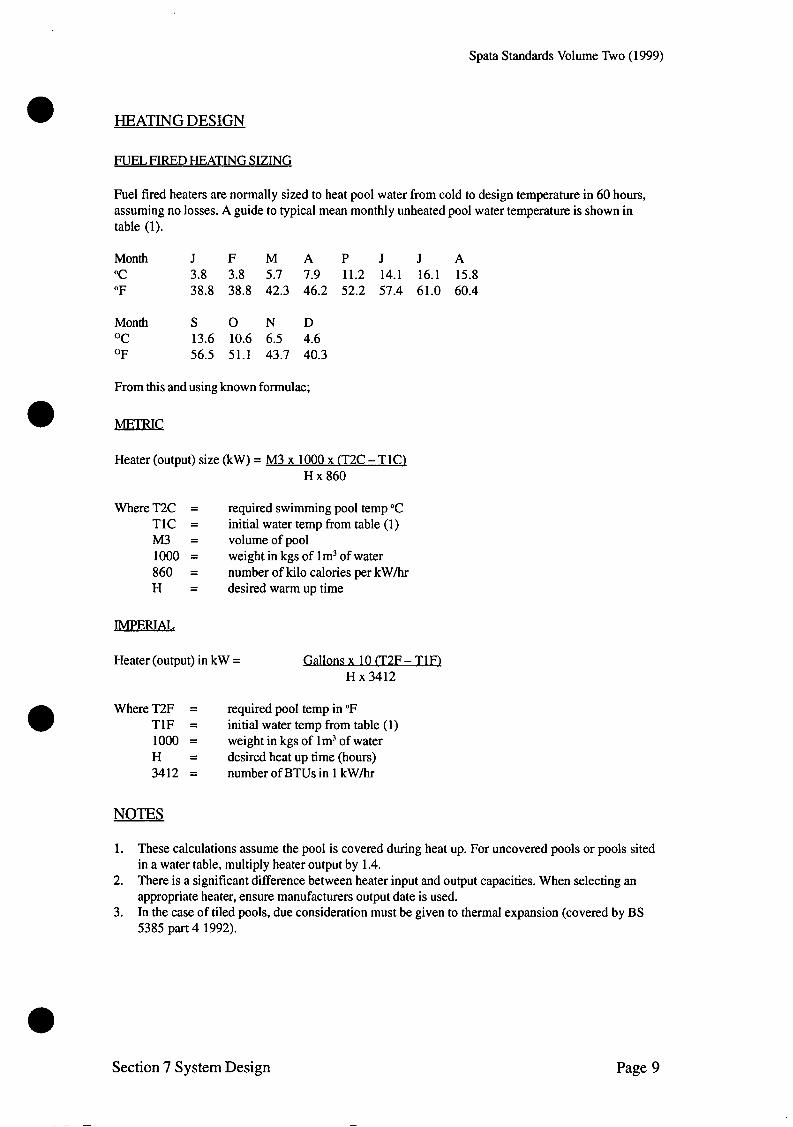
Spata Standards Volume Two (1999)
HEATING DESIGN
FUEL FIRED HEATING SIZING
Fuel fired heaters are normally sized to heat pool water from cold to design temperature in 60 hours, assuming no losses. A guide to typical mean monthly unheated pool water temperature is shown in table (1).
Month J F M A P J J A "C 3.8 3.8 5.7 7.9 11.2 14.1 16.1 15.8 "F 38.8 38.8 42.3 46.2 52.2 57.4 61.0 60.4
Month S O N D OC 13.6 10.6 6.5 4.6 OF 56.5 51.1 43.7 40.3
From this and using known formulae;
Heater (output) size (kW) = M3 x 1000 x (T2C - TlCl H x 860
Where T2C = required swimming pool temp "C T1C = initial water temp from table (1) M3 = volumeofpool 1000 = weight in kgs of lm3 of water 860 = number of kilo calories per kW/hr H = desiredwarmuptime
IMPERIAL
Heater (output) in kW = Gallons x 10 (T2F - T 1 n H x 3412
Where T2F = required pool temp in "F T1F = initial water temp from table (1) 1000 = weight in kgs of lm3 of water H = desired heat up time (hours) 3412 = number of BTUs in 1 kW/hr
NOTES
1.
2.
3.
These calculations assume the pool is covered during heat up. For uncovered pools or pools sited in a water table, multiply heater output by 1.4. There is a significant difference between heater input and output capacities. When selecting an appropriate heater, ensure manufacturers output date is used. In the case of tiled pools, due consideration must be given to thermal expansion (covered by BS 5385 part 4 1992).
Section 7 System Design Page 9
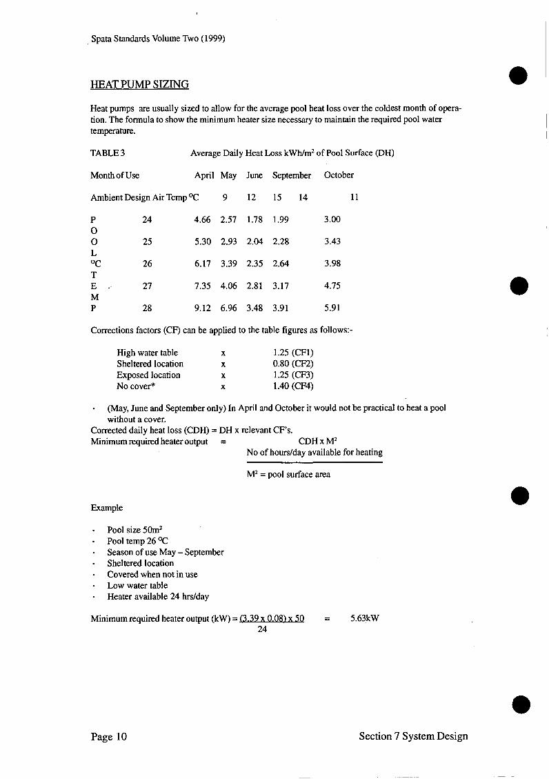
Spata Standards Volume Two (1999)
HEAT PUMP SIZING
Heat pumps are usually sized to allow for the average pool heat loss over the coldest month of opera- tion. The formula to show the minimum heater size necessary to maintain the required pool water temperature.
TABLE 3 Average Daily Heat Loss kWh/m2 of Pool Surface @H)
Month of Use April May June September October
Ambient Design Air Temp OC 9 12 15 14 11
P 24 4.66 2.57 1.78 1.99 3.00 0 0 25 5.30 2.93 2.04 2.28 3.43
OC 26 6.17 3.39 2.35 2.64 3.98 T E . 27 7.35 4.06 2.81 3.17 4.75 M P 28 9.12 6.96 3.48 3.91 5.91
Corrections factors (CF) can be applied to the table figures as follows:-
High water table X 1.25 (CFl) Sheltered location X 0.80 (CF2) Exposed location X 1.25 (CF3) No cover* X 1.40 (CF4)
- Corrected daily heat loss (CDH) = DH x relevant CF’s. Minimum required heater output = CDH x M2
(May, June and September only) In April and October it would not be practical to heat a pool without a cover.
No of hours/day available for heating
M2 = pool surface area
Example
- Pool size 50m2 - Pool temp 26 OC - Season of use May - September - Sheltered location - Covered when not in use - Low water table - Heater available 24 hrdday
Minimum required heater output (kW) = f3.39 x 0.08) x 5Q = 5.63kW 24
Page 10 Section 7 System Design
~~ -~
e
Spata Standards Volume Two (1999)
DEHUMIDIFICATION DESIGN
CALCULATION FOR DEHUMIDIFICATION FRESH AIR REOUIREMENT
Assume pool conditions of 3OoC and 60% RH. This is 21.4 OC Dew point and equates to (1) O.O16Kg/ Kg moisture content. Assume British summer outdoor conditions of 18 OC Dew point.
Typically 23 "C at 73% RH, a specific volume of 0.855 m3/Kg. And equates to (2) 0.013Kg/Kg moisture content
Therefore the Natural Fresh Air dehumidification capacity = - (2) that is:- O.O16Kg/Kg - 0.013Kg/Kg = (1)
A busy swimming pool can be expected to evaporate at a rate of circa 22 litres (Kg)/100m2
That is 0.22Kg of evaporation per m2 of pool wetted area.
- So 0.22Kdm2 x 0.855m3/Kg - 0.003KgKg
62.7m3 of fresh air per/m2 of pool area
This is an exact figure and should be rounded up to:-
65m3 of fresh air per hour per lm2 of pool wetted area.
Section 7 System Design Page 11

Spata Standards Volume Two (1999)

~~
Spata Standards Volume Two (1 999)
a
SECTION 8
a HEALTH AND SAFETY
a

~~~ ~ ~~~~ ~ ~
Spata Standards Volume Two (1999)

SECTION 8 - HEALTH AND SAFETY
This section deals with both the Health and Safety requirements for construction of a pool and the Health and Safety requirements for operation.
Whilst there are no mandatory swimming pool regulations laid down by any official body, The Swim- ming Pool and Allied Trades Association makes the following recommendations as a basis for safety precautions to control swimming and save life in an emergency as far as all swimming pools are concerned. These standards are designed to compliment the recommendations of the Health and Safety Executive and the English Sports Council. Readers are advised to familiarise themselves with ‘manag- ing Health and Safety in swimming pools (1999)’.
Leisure activities can be dangerous and personal safety is the priority!
The swimming pool area must be designed to suit the use or activity, especially where recreational diving and sliding is involved. Pools for the general public must be supervised. Strict design standards apply to competitive diving, activity accessories such as fluming and wave making, and to hygiene control.
Although modem design of facilities may be highly satisfactory, it is nearly always the misuse of equipment and provisions that causes accidents. The operation of all mechanical equipment should be assessed and full training provided to ensure against such misuse.
Appropriate training, planning and effective and trained supervision at all times will ensure this. Pools and plant rooms need to be secured against unauthorised access at all times. It is the responsibility of the Pool Contractor to control all hazards during construction and it is the responsibility of the pool owner or pool management to prevent accidents during operation.
Section 8 Health and Safety Page 1
Spata Standards Volume Two (1999)
DURING OPERATION
LIFESAVING (DOMESTIC POOLS)
Whilst it is not possible to enforce rigid standards for domestic pools the following safety aids should be considered.
One throw bag (DTI approved) with a 30mm (1.25in) circumference. Courlene or equivalent heavy line, diameter 5mm (0.25in), of a length not less than 1.5 times the maximum width of the pool, with a breaking strain not less than 550 kilograms (12201bs). Alternatively a rescue quoit and line may be substituted provided the above criteria are met.
A suitable Fire extinguisher of a size suitable to deal with the area concerned. Suitable signage eg. No diving, accurate water depth. One pair of large sharp scissors
- One life pole or hook with a minimum handle length of 3.5m (12ft).
The above items should be sited adjacent to the pool and readily available in case of an emergency.
LIFEGUARDING (COMMERCIAL POOLS)
HSE considers any pool or combination of pools with an area greater than 17Om2 or a depth greater than 1.5m at any point requires continuous lifeguard provision.
Any such public swimming pool shall be under the supervision of a person or persons qualified in the field of lifeguarding, first aid, filter operation and sanitisation, or under whose direct supervision are employed persons qualified in lifeguarding. Each such person should be responsible for no more than 17Om2. of pool surface area and to avoid lack of concentration it is recommended that station changes are instituted every 20 minutes. Where flumes or wave machines are in operation at least one lifeguard should be stationed with this sole responsibility.
Individuals shall be considered qualified:- in lifeguarding if they hold qualification meeting HSE/ESC guidance in pool and plant operation if they hold the appropriate I S M L A M Certificate or similar approved certificate
The safety aids which should be installed in each public pool are as follows:-
At least one elevated lifeguard chair for 185m2 (2000ft2) of pool surface area or any major fraction thereof. Where a pool is provided with more than one lifeguard chair and the pool width is 12m (40ft) or more they shall be located on either side of the pool.
One DTI approved throw bag, the internal diameter of which shall be 0.5m (1.5ft) with a 3Omm (1.25in) circumference. Courlene or the equivalent heavy line -diameter 5mm (0.25in) of a length not less than 1.5 times the maximum width of the pool, which line shall have a breaking strain of not less than 550 kilograms (12201bs).
- A life pole or life hook with a minimum handle length of 3.5m (12ft).
Comprehensive First Aid Kit. There may be a need for more specialised equipment eg. Resuscitation masks (with or without 0 2 reinforcement), spine boards, emergency defibrillation equipment. It should be noted however each of these requires the associated high level of training for staff.
Page 2 Section 8 Health and Safety

. . *.L b'.,
Spata Standards Volume Two (1 999)
Note: The HSE does not recommended the provision of mechanical resuscitation equipment other than for parmedically qualified staff.
a
Life guarding equipment shall be mounted in conspicuous places distributed around the pool edge at lifeguard chairs or elsewhere, readily accessible with its function plainly marked. It is recommended that a cut out system should be installed adjacent to the pool to permit immediate switch off of pumps and consequent suction within the pool. A clearly labelled means of summoning assistance shall be provided at each guard chair andor in the immediate pool surround area for possible emergency use. These telephone andor alarms shall be housed in weatherproof easily accessible cabinets painted green, which shall be vandal proof. It is recommended that it should be mandatory for the responsible supervisor on duty to notify his immediate superior if:
1. 2.
The clarity of water becomes less than that laid down in these standards. The chlorine and pH levels at any time are outside the limits set by the Supervisory Board, or in general are not in accordance with the levels laid down in these standards or any other recognised Authority. Any substance including diarrhoea or vomit are introduced into the pool water. It should be noted that normal faeces in correctly balanced and sanitised water will not be harmful and can simply be removed. When there is entrapment or drowning.
3.
4.
In the interests of health and safety, when such conditions as described above occur, the pool should be closed until such time as it is bought back to an acceptable condition as laid down in these standards.
The number of bathers permitted to use any public pool should be controlled within the limits of the pool capacity by the use of turnstiles andor locker space, designed to limit the number of people permitted to have access to the pool at any one time.
Commercial swimming pools shall be protected from unauthorised entry. Access to the pool by bathers shall be provided either through the pool hall, the dressing room or some other controlled entry.
SAFETY PRECAUTIONS
The filter house of all commercial swimming pools shall be provided with approved type fire extin- guishers of a size suitable to deal with the area concerned, which extinguishers shall be particularly suitable for the extinguishing of electrical fires and not incompatible with the chemicals in use for sterilisation of the swimming pool.
The local Fire Prevention Officer should be contacted and his recommendations followed when designing and equipping the filter house and chlorine compartment and in particular and the swimming pool complex generally.
Such fire fighting apparatus shall be sited outside the area of the potential fire and shall be readily accessible.
Fire fighting points should be clearly marked, and alarm bells and switches installed in strategic places.
The pool management staff shall be trained in fire fighting duties and a roster shall be kept designating the fire point to which each of the personnel shall proceed in the event of an alarm being sounded.
Section 8 Health and Safety Page 3
Spata Standards Volume Two (1999)
CHEMICALS
Incompatible chemicals shall not be stored in the same compartment where inadvertent mixing may cause an explosion or the production of poisonous gases, with the possibility of serious injury or death. Chemicals in common use in pool water treatment are listed in SPATA Standards for swimming pools Volume 3 - water and chemicals which also designates their incompatibility.
Note - As far as the use of chlorine gas is concerned, it should be noted that suppliers of chlorine gas cylinders will not deliver these unless they are satisfied that the chlorine compartment and equipment is in accordance with current regulations.
ELECTRICAL
All the recommendations set out in the electrical section shall be complied with in the interests of safety.
DURING CONSTRUCTION
It is the responsibility of all individuals concerned with the design, planning construction, operation and maintenance of a swimming pool and its associated facilities to identify and assess hazards, to minimise risks to all persons and to regularly monitor review such procedures.
LEGAL REOUREMENTS
CONSTRUCTION AND INSTALLATION
It is the responsibility of all parties involved in the construction and operation of a swimming pool to be fully conversant with current Health and Safety Regulations and to undertake any necessary condi- tions these regulations may impose. This summary provides only a guide and the importance of famil- iarisation with all current legal requirements is emphasised.
1. The Health and Safety requirements fall predominantly under the following legalisation:- The Health and Safety at Work Act 1974 COSHH (Control of Substances Hazardous to Health) 1994 CHIPS (Chemicals Hazard, Information and Packaging Regulations) 1994 Electricity at Work Regulations 1989 (Incorporating IEE 16'" Edition)
But also requires that operations conform with:- Construction Design Management Regulations 1994 Provision and Use of Work Equipment Regulations 1992 Manual Handling Regulations 1992
2. A summary of the relevant requirements of these regulations is:- The employer must protect his employees, fellow workers and the public from danger. The employee has the same responsibility All electrical equipment should be inspected and tested before use and serviced regularly. All electrical works should comply with IEE 16"' Edition or its successor.
Page 4 Section 8 Health and Safety

Spata Standards Volume Two (1999)
PERMIT TO WORK
When working in a confined space - specifically a balance tank, possibly a small poorly ventilated plant room and certainly underwater, it is legally necessary to provide a Permit to Work. This docu- ment should contain:-
Identification of the site Identification of the work involved Names of operators and qualifications Date and approx time of work Equipment to be used Safety measures to be taken Controls to be enforced Signature of authorised person
SEE SPECIMEN 1
RISK ASSESSMENTS
For every physical feature, activityhsk and user group with an associated risk a Risk Assessment should be produced. This should show:-
The Hazards Who may be at risk The level of risks What controls are to be introduced to reduce the risk The level of risk after control
SEE SPECIMEN 2
Section 8 Health and Safety Page 5
Spata Standards Volume Two (1999)
COSHH DATA SHEETS
For every chemical supply it is necessary to supply a Safety Data Sheet which identifies:- The chemical components The hazards associated therewith The application of the chemical Safety controls to be instituted The action to be taken in case of accidents. Movement and action
6. All safety controls should be regularly monitored, recorded and reviewed.
7. CDM requirements are summarised as follows:-
THE CONSTRUCTION (DESIGN AND MANAGEMENT) REGULATIONS 1994 introduce and control covering design, commissioning of work, planning and execution, and apply to all construction work likely to pose significant risks to workers and other parties. This summary provides only a guide to the Regulations and thorough knowledge of the CDM regulations is recommended for all parties where construction work is subject to the Regulations.
The Regulations apply to construction work which:
- - - - -
lasts for more than 30 days, or will involve more than 500 person days of work, or includes any demolition work (regardless of duration or size), or involves five or more workers being on site at any one time. All design work for construction
The Regulations do not apply where the work is minor in nature i.e. done by people who normally work on the premises. It is either not notifiable, or entirely internal, or carried out in an area which is not physically segregated, normal work is carrying on and the contractor has no authority to exclude people while it is being done, or where it is carried out in premises normally inspected by the local authority (sports premises). Maintaining or removing insulation on pipes or boilers, or other parts of heating and hot water systems is not classed as ‘minor work’.
DEFINITIONS under these Regulations should be noted carefullv.
‘Agent’ means any person who acts as agent for a client in connection with the carrying on by the person of a trade, business or other undertaking, whether for profit or not.
‘Client’ means any person for whom a project is carried out, whether the project is carried out in- house or by another person.
‘Construction Work’ means the carrying out of any building, civil engineering construction work, and includes any of the following:
1. Construction, alteration, conversion, fitting out, commissioning, renovation, repair, upkeep, redecoration or other maintenance (including cleaning which involves the use of water or an abrasive at high pressure or the use of corrosive or toxic substances,) decommissioning, demoli- tion or dismantling of a structure;
2. Preparation for an intended structure including site clearance, exploration, investigation (but not site survey) and excavation, and laying or installing the foundations of the structure;
3. Assembly or disassembly of prefabricated elements of a structure; 4. Removal of a structure or part of a structure, or of any product or waste resulting from demolition
or dismantling of a structure or disassembly of prefabricated elements of a structure;
Page 6 Section 8 Health and Safety

. . . . ’ . ’ . ., . . . . I ’ ,
Spata Standards Volume Two (1999)
5 . Installation, commissioning, maintenance, repair or removal of mechanical, electrical, gas, compressed air, hydraulic, telecommunications, computer or similar services which are normally fixed within or to a structure.
e ‘Contractor’ means any person who carries on a trade or business or other undertaking, whether for profit or not, in connection with which he undertakes to or does manage construction work, or arranges for any person at work under his control (including any employee, where he is an employer) to carry out or manage construction work. This definition can therefore be applied to the self employed.
‘Design’ in relation to any structure includes drawing, design details, specification and bill of quanti- ties (including specification of articles or substances) in relation to the structure.
‘Designer’ means any person who carries on a trade, business or other undertaking in connection with which he prepares a design or arranges for any person under his control to prepare a design relating to a structure or part of a structure.
‘Health and Safety fide’ means a file or other record in permanent form containing the information required by Regulation 14(d) - about the design, methods and materials used in the construction of a structure which may be necessary for appropriate third parties to know about for their health or safety.
‘Project’ means a project which includes or is intended to include construction work.
e ‘Structure’ in this context means any building, steel or reinforced concrete structure (not being a building), dock, harbour, waterworks, reservoir, pipe or pipeline (regardless of intended or actual contents), cable, aqueduct, sewer, sewage works, river works, drainage works, earth works, lagoon, dam, underground tank, earth retaining structure or structure designed to preserve or alter any natural feature, and any similar structure to these, and any form work, false work, scaffold or other structure designed or used to provide support or means of access during construction work, and any fixed plant in respect of work which is installation, commissioning, decommissioning, or dismantling and where that work involves a risk of falling more than 2m.
Section 8 Health and Safety Page 7

Spata Standards Volume Two (1999)
THE REQUIREMENTS OF THE REGULATIONS
Regulation 4 covers clients who when appointing agents must be reasonably satisfied about their competence to carry out the duties given to the clients by the Regulations. A declaration is sent to the HSE, which is required to acknowledge and date the receipt of it.
Regulation 6 requires every client to appoint a planning supervisor and principal contractor in respect of each project
Regulation 7 requires the planning supervisor to give written notice of notifiable projects to the HSE, as soon as practicable after his appointment as planning supervisor (Parts I and 11) and as soon as practicable after the appointment of the principal contractor (Parts I and 111), and in any event before the start of the construction work. Where work which is notifiable is done for a domestic client and a developer is not involved, then the contractor(s) doing the work have the responsibility of notifying the HSE, and one of these can notify on behalf of any others. Again, notification must be made before any work starts.
Regulation 8 + 9 covers the requirements for competence of planning supervisor, designers and contractors. The client must take necessary steps to be reasonably satisfied that a potential planning supervisor is competent and has adequate resources to perform the functions required by these Regula- tions, before any person is appointed to the role (Regulation 8(1)).
The client is required by Regulation 10 to ensure so far as is reasonably practicable that a health and safety plan which complies with Regulation 15 (4) has been prepared in respect of the project before the construction phase starts.
Regulation 11 obliges the client to ensure that the planning supervisor is provided as soon as practica- ble and before work starts with information relevant to his functions about the state or condition of any premises where relevant construction work will be carried out.
The client is required by Regulation 12 to take reasonable steps to ensure that the information in any health and safety file which is given to him is kept available for inspection.
Designers’ duties are given in Regulation 13. Except where the design is prepared in house, employ- ers cannot allow employees to prepare a design, and no self employed person can prepare a design, unless the employer has taken reasonable steps to make the client for the project aware of the duties of the client within these Regulations and any practical HSC guidance on how to comply.
The designer is firstly to ensure that any design he prepares and which he knows will be used for construction work includes adequate regard to three needs:
1. to avoid foreseeable risks to health and safety of those constructing or cleaning the structure at any time and anyone who may be affected by that work
2. that risks to constructors or cleaners of the structure at any time, or to anyone who may be affected by that work, are combated at source, and
3. that priority is given to measures which will protect all such persons over measures which only protect each person at work.
Secondly, the designer is to ensure the design includes adequate information about any aspect of the project, structure or materials to be used which might affect the health and safety of constructors, cleaners or anyone who may be affected by their work.,
Thirdly, a (stronger) duty to co-operate with the planning supervisor and any other designer is placed on a designer, so far as is necessary to enable each of them to comply with health and safety laws.
Page 8 Section 8 Health and Safety

Spata Standards Volume Two (1999)
Regulation 14 details the main duties of the planning supervisor. This duty holder must: a a) ensure as far as is reasonably practicable the design of any structure in the project complies with
the needs specified in Regulation 13 and includes adequate information. b) Take reasonable steps to ensure co-operation between designers to enable each to comply with
Regulation 13. c) Be in a position to advise any client and any contractor to enable them to comply with Regulations
8(2) and 9(2) - competence of designer - and to advise any client on compliance with Regulations 8(3), 9(3) and lO(competence of contractor and readiness of the health and safety plan), and
d) Ensure that a health and safety file is prepared in respect of each structure in the project, reviewing and amending it over time, and finally delivering it to the client on completion of construction work on each structure.
Regulation 15 sets out the specific requirements for the health and safety plan. This is to be prepared by the appointed planning supervisor so as to contain the required information and be available for provision to any contractor before arrangements are made for the contractor to carry out or manage construction work on the project.
The required information to go into the plan is:
- - -
a general description of the construction work details of the intended timescale for the project and any intermediate stages details of any risks known to the planning supervisor or which are reasonably foreseeable risks to the health and safety of constructors any other information which the planning supervisor has or could reasonably get which a contrac- tor would need to show he has the necessary competence or has or will get the adequate resources required by Regulation 9, and information which the principal contractor and other contractors could reasonably need to satisfy their own duties under the Regulations.
-
-
The principal contractor must take reasonable steps to ensure the plan contains until the end of the construction phase the required features, which are:
- arrangements for the project which will ensure so far as is reasonably practicable the health and safety of all constructors and those who may be affected by the work, taking account of the risks involved in the work and any activity in the premises which could put any people at risk sufficient information about welfare arrangements to enable any contractor to understand how he can comply with any duties placed on him in respect of welfare arrangements which will include where necessary the method of managing the construction work and monitoring of compliance with health and safety regulations.
-
-
Regulation 16 specifies the duties and powers of the principal contractor to take reasonable steps to ensure co-operation between contractors so far as is necessary to enable each to comply with require- ments imposed and to ensure so far is reasonably practicable that every contractor and every employee complies with any rules in the health and safety plan. The principal contractor must also take reason- able steps to ensure that only authorised persons are allowed where construction work is being carried out and ensure that required particulars are displayed in a readable condition in notice covered by Regulation 7.
He must also provide the planning supervisor promptly with any information he possesses or could reasonably find out from a contractor which the planning supervisor does not already possess and which could reasonably be believed necessary to include in the health and safety plan.
Section 8 Health and Safety Page 9
Spata Standards Volume Two (1999)
Duties on the giving of information and training requirements are set out in Regulation 17. The princi- pal contractor must (as far as is reasonably practicable) ensure that every contractor is provided with comprehensible information on the risks to himself and any employees or persons under his control which are present as a result of the work. Provision is made by Regulation 18 for receipt of advice from employees and the self employed by the principal contractor, who must ensure that discussion and advice on health and safety matters is provided.
Contractors’ duties are covered by Regulation 19 (l), where in relation to a project they must co- operate with the principal contractor as necessary, provide the principal contractor with any relevant information which might affect anyone’s health or safety whilst on the project. This includes relevant risk assessments, and any information which might prompt a review of the safety plan for the project.
The Regulation requires contractors to provide the principal contractor with any information which is notifiable by the contractor to the enforcing authority under RIDDOR - details of injuries, diseases and dangerous occurrences as defined which are related to the project.
Regulation 19 contains in parts (2), (3) and (4) general requirements to be observed by employers with employees working on construction work, and the self employed including the names of the planning supervisor, principal contractor and the health and safety plan or relevant parts of it.
The Regulations have the same coverage as the Health and Safety at Work etc. Act 1974 by Regulation 20, and, except for hvo of them, do not confer a right of civil action (Regulation 21).
Five duties of designers:
Avoid foreseeable risks Combat risks at source Protect all people rather than individuals Include information Co-operate with the Planning Supervisor
Five duties of the client:
Appoint the Planning Supervisor and Principal Contractor Be satisfied about their competence Give information about the structure Establish the safety plan is in place before work starts Keep the safety file available for inspection
Page 10 Section 8 Health and Safety
~~~~~~~
Spata Standards Volume Two (1 999)
SECTION 9
COMMISSIONING
OPERATION AND
MAINTENANCE

~~ ~
Spata Standards Volume Two (1999)

Spata Standards Volume Two (1999)
0 SECTION 9 - COMMISSIONING OPERATION AND MAINTENANCE
COMMISSIONING. DEMONSTRATION AND HANDOVER
COMMISSIONING
1. Where a contract provides for the supply only of equipment for installation by others the supplier shall provide full written instructions for the safe and correct installation of the equipment together with instructions for its operation for onward transmission to the end user.
2. Where a contract provides for the supply and installation of equipment forming a part of a com- plete pool plant installation the installer must ensure that the equipment is suitable for its purpose and is installed in accordance with the makers instructions and all relevant standards and codes of practice. Where a contract provides for the complete installation of a pool with its associated water treat- ment system the contractor must ensure that all equipment is properly installed, in working order and fully commissioned before attempting to hand over the installation to the end user. In the case of a swimming pool this means ensuring that (save only for minor ‘snagging items’):-
3.
- - - - -
The walls and floor of the pool are thoroughly cleaned. The water is clear and free from suspended matter. The pool water chemistry is correctly adjusted and balanced. The filter is operating correctly and has been recently backwashed. The water header (if fitted) is operating and (unless otherwise agreed with the client) has raised the water to the required temperature. The chemical dosing system (if fitted) is fully charged with appropriate reagents and working
The environmental control system (if fitted) is working correctly and has achieved the re- quired air temperature and relative humidity in the pool hall.
- correctly. -
PEMONSTRATION
The Contractor should provide a fully operational demonstration to the Client/Client’s Agent before handover. This demonstration should include a thorough introduction to all elements of the pool equipment, pool water, pool area and health and safety requirements. The Operation and Maintenance Manual should be available for familiarisation and any questions should be fully explained (in writing if reauired).
Section 9 Commissioning, Operation and Maintenance Page 1

Spata Standards Volume Two (1999)
“DOVER
1.
2.
3.
4.
5.
6.
7.
Before any hand over is attempted all goods and services, maintenance equipment and water treatment chemicals required by the Contract must be delivered to site and (where appropriate) installed and working. The Contractor shall then provide such oral and written instruction as may be necessary to ensure that the client or the client’s agent understands all aspects of the operation of the pool and its associated equipment and chemical dosing system. Written instructions must be in a coherent form specially drafted and appropriate for the complete installation in question. On completion of the hand over the contractor and client shall sign and exchange duplicate copies of a ‘handover certificate’ in a form not less satisfactory than the standard SPATA Handover Certificate. This certificate shall list any minor snagging work which remains outstanding and the contractor’s proposals for its completion and should constitute ‘practical completion’ insofar as Insurance cover, maintenance liability and warranties are concerned. The contractor shall, where appropriate, include in the Operation and Maintenance Manual copies of the Electrical Completion Certificate in the form specified by BS7671 (The IEE Wiring Regula- tions) together with evidence of Consents under Planning and Building and any other relevant Regulations. In the case of public swimming pools, the contractor should, unless totally satisfied that the Plant Operating Engineer has sufficient relevant past experience, require and request the Client to provide satisfactory basic training in plant operation (ideally the Pool and Plant Operators Course by the ISRM) and water treatment before final completion of the handover. In commercial pool contracts the contractor shall also supply to the Client required safety informa- tion for inclusion in the Project Safety File. This information should include:- - Risk Assessments - COS” Data Sheets - Emergency Procedures In so far as they apply to the pool and plant. Further risk assessment, COSHH assessment and emergency procedures are required to be devel-
oped and instituted by the operator taking into account specific peculiarities of the operation.
Page 2 Section 9 Commissioning, Operation and Maintenance

Spata Standards Volume Two (1999)
OPERATION AND MAINTENANCE MANUALS
A comprehensive Operation and Maintenance Manual should be supplied to the Client on handover. A private pool should be provided with a single copy and a public pool with 4 copies. Each manual should be specific to the installation and bound in a looseleaf, hardwearing binder and should contain:-
1. 2. 3. 4. Maintenance requirements 5. Servicing requirements 6. Emergency plant procedures 7. Manufacturers guides and maintenance manuals 8. Water treatment guide with testing procedures 9. Notice of chemicals to be used 10. Guarantees and warranties
Specification of contract equipment including serial numbers and manufacturers name & address Specification of pool with dimensions and capacity and construction detail Day to day running instructions in a concise and understandable format
Manuals for public pools should also contain:-
1. As built drawings - 2. Spares requirement list 3. 4.
Safety file with safety data sheets Copies of all test certificates
During demonstration the Operation and Maintenance Manual should be made available to the pool plant operator and the contents explained in detail. One set in plant room and one set in managers office.
It is recommended that a subsequent visit after sufficient time has lapsed for the operator to familiarise himherself with the contents of the manual and the pool equipment should be made.
Commercial Contracts must also be supplied with a Safety File containing:-
- - - Safety procedures and precautions
Risk Assessments for any potential hazard COS" Safety Data Sheets for all chemicals likely to be used
Section 9 Commissioning, Operation and Maintenance
~ ~~
Page 3
~~~

Spata Standards Volume Two (1999)
RESPONSIBILITIES
NUFACTURER AND SUPPL IERS RESPONS IBILITY
It is a requirement that all manufacturers or suppliers of filters or filtration ancillary equipment to supply with their filters andor equipment the following:-
1. Name and address of manufacturers andor supplier or service agent. 2. Full operating instructions for the specific equipment with schematic drawings and performance
curves etc. 3. Maintenance instructions with identification of spare parts. 4. Guarantees and warranty details.
RESPONSIBILITY OF THE POOL OWNEWOPERATOR
Although the following requirements are not enforceable of the owner, neither the manufacturer nor the installer can accept any responsibility for damage, accident or injury arising from the owners failure to conform with these recommendations. It is therefore recommended that the following requirements are reproduced and explained within the Operation and Maintenance Manuals.
1.
2.
3. 4. 5.
6. 7.
8. 9.
The owner, or his agent or his representative should read the Operation and Maintenance Manual including the manufacturers operating and maintenance instructions carefully, and attend a demon- stration of the normal operating procedure with the installer before taking over the operation of the
He should pay particular care to chemical treatment of the water with special regard to chlorine limits and control of pH values. Where automatic or semi automatic chlorine addition is provided it is essential that this only occurs when the pump is running, otherwise high concentrations build up in the pipework and heating plant. Pool chemicals must be stored in a dry position away from the heating and electrical equipment. Water leaks from pipework or fittings must be attended to at once. Heaters must not become cluttered up with oddments which can restrict ventilation or cause overheating and fire risk, as can happen if the heater is used to dry out clothing or towels. Maintenance should be carried out regularly in accordance with the manufacturers instructions. The equipment of outdoor pools should be fully winterised each year as described by the supplier and in accordance with SPATA recommendations. The identification plate details should be quoted when communicating with the manufacturer. Running costs are entirely in the hands of the owner. For maximum economy of fuel or power, the owner should consider the regular use of a pool cover.
pool.
10. Where the installer, or owner, shall decide to use heating equipment not specifically designed or adapted for swimming pool heating (or where equipment is used which does not comply with these standards) they shall assume the responsibility of the manufacturer as set out above and shall ensure that the final installation is so adapted as to comply with these standards.
11. No electrical appliances other than specialist swimming pool equipment correctly installed by a qualified Electrician in accordance with IEE Regulations should be permitted in the pool hall area.
12. The owner has a ‘Duty of Care’ 1932 to ensure the safety of any persons coming into contact with the swimming pool. SPATA recommend therefore that suitable signage should be provided to prevent danger or accident which may be caused by slipping, tripping, broken glass or other debris, and general use of the pool. I.e. No Diving etc.
Page 4 Section 9 Commissioning, Operation and Maintenance
Spata Standards Volume Two (1999)
SECTION 10
GLOSSARY
ACKNOWLEDGEMENTS

Spata Standards Volume Two (1999)
a
a
. . . . . . I , 4 -.. . Spata Standards Volume Two (1999)
SECTION 10 - GLOSSARY AND ACKNOWLEDGEMENTS
The text of these standards refers to and explains many of the terms used in connection with the swimming pool installation. The following glossary is included however to give handy non-technical reference to terms in common use:-
Air Change Rate:
Air Curtain:
Air Filter:
Air Handling Unit: (A.H.U.)
Air Scour:
Anti-vortex Fitting:
Attenuator:
Backwash:
Backwash Cycle:
Backwash Rate:
Balance Pipe:
Balance %nk:
Balance valve:
Body Feed:
Boiler:
Boiler - Balanced Flue:
Boiler - Conventional Flue:
Boiler - Direct Fired:
Boiler-Indirect Fired:
Boiler - By Pass Pipe:
Boiler - Condensing 5 p e :
Boiler - Pressurised: Over Run:
The proportion of fresh air which is introduced into the pool hall within aspecific period of time.
The term used when air is intentionally distlibuutedover asurface, typically glazing within the pool hall, in order to achieve a localisedenvironment to assist in preventing the formation of surface condensation or where asingleopen space may have differing temperature Zones.
A filter to remove dust and small particles from the. air stream, prior to entering the environmental control unit or duct work.
Any product that mechanically ventilates air.
A device operated pneumatically to break up, lift and help cleanse asand bed and flocculating agent in the sand filters by agitating the bed on the backwash. It also reduces the backwash time and consequently the backwash water required
A cover for a water suction fiuing within the swimming pool which is designed to minimise the formation of vortices and the risk of entrapment of partsof the human M y .
A device used to reduce noise transfer, usually positioned within the air ductwork channels leading to the environmental control equipment.
The process of flow reversal to clean a pool water filter and restore it to the normal clean condition offilteringwithaminimumresistancetoflowthroughthemedia
The operating time, after the filter cycle, required to completely clean the filter.
The rate of application of water through a filter during the cleaning cycle expressed in capacity per minute. per effective filter surface area
Pipe which transfers pool water either between two adjacent pools (i.e. main pool and children's pool) or between pool and auto water level unit.
A vessel which is used to control water level.
Float operated valve within balance tank to control volume of water for pool floor outlets, sumps,
The continuous addition of small amountsof filter aid during the operation of adiatemaceousearth mm.
A product which releases heat energy through combustion of a fossil fuel. The heat released can then be used as a heating medium.
A boiler equipped with a balanced flue takes the air ventilation it requires from the flue pipe and not from the room in which it is positioned.
Aboilerequippedwithaconventional fluetakestheairventilationit requires from immediate surrounding area. Such boilers should not be used in conjunction with plant room air plenum chambers.
A direct fired boiler enables the pool water passed through the boiler to pick up the heat directly from the pool combustion process.
With an indirect f d boiler, the. heat from the combustion process is passed into an additional medium, usually a LPHW circuit,and then transfemed into the pool water via a heat exchanger.
When the flow of LPHW from the boiler is diverted so that it returns back to the boiler without passing through any heater.
A typeofboilerwhichcanobtainimprovedoper;llingefficiencybycooling the flue gases and returning the heat to the system. Can be used in place of normal boiler types.
When the heating device or boiler circulating pump continues to Over Run: intentionally operate for a timed period after the heating requirement has been satisfied in order to dissipate residual heat from the. boiler.
Spata Standards Volume Two (1999)
Boiler -System:
Boiler Thermostat:
Boiler Demand Signal:
BTU:
Glorifier:
Cartridge Filter:
Compressor Motor:
Condensation - Interstitial:
Condensate:
Condenser (Air):
Condenser (Water):
Condenser (Remote):
Convection:
Corrosion:
Corrosion Resistant Material:
Counter Current Unit:
cross Connection:
Damper:
Damper Actuator:
Deck Level Pools:
Deck Level Grating:
De-frost:
A type of boiler system where the entire pipework system is maintained at pressure. Can be used in place of normal boiler types.
The thermostat normally located within the boiler which regulates the outlet temperature of the LPHW from the boiler. Typically around 82d.
Normally a switch electrical feed provided from the heating control motorised valves to enable the boiler to be shut down completely when no heating demand is present.
An abbreviationof ‘Britishlhermal Unit’.Commonlyusedto indicatetheheatcapacityofboilers and heat exchangers etc. 3412.14BTU’s=lkwBTU/hr=KW.
An alternative term for heating coil or heat exchanger.
Afilterusingadisposableorrenewable filterelement
The main motor of any refrigeration circuit (i.e. heat pump or dehumidifier). The compressor, which is invariably electrically driven, pumps refrigerant increasing both its pressure and temperature.
When condensation occu~s actually within the material of the pool hall building strucl~re, as opposed to condensation only forming on the surface.
The condensed water vapour which will be apparent on any surface cold enough to be below the dew point temperature. Within adehumidification unit the condensate is normally collected in atray and drained away.
Often similar in appearance to a m radiator coil, an air condenser of this type is positioned within the pool hall air stream, usually within an environmental control unit. The purpose of an air condenser coil is to transfer heat from arefigeration circuit (heat pump) into the air stream. The term condenser is derived from the effect on the refrigerant as it passes through the coil - it enters as a hot gas which, as it is cooled by the air, condenses to a liquid.
The purpose of a water condenser coil is to transfer heat fkom arefigeration circuit (Heat pump) intowater,usuallythepool wateritselfwhichispumpedthroughthe watercondenser.
A condenser of this type positioned outside the building in fresh air. The plupose of aremote air condenser coil is to transfer heat from the refrigeration circuit (heat pump) into fresh air. Usually this would dissipate heat which was not required anywhere else and can be used as part of an ‘air conditioning’ cooling system
Transfer of heat by air movement
The loss of material due to chemical discharge.
A material with an exceptional resistance to the comsion factors to which it issubjected.
A pumping system mounted within or on the pool shell wall which pmduces acurrentof water, sufficiently strong enough to enable bathers to swim against it without moving in the pool.
An unprotected connection between a domestic water system and any pool or other non-potable water whereby back flow to the domestic system could occur. Appropriate protection may be air gaps, non-return valves or other methods.
A series of metal plates positioned within the air stream duct work which can be closed together to restrict andor prevent the passing air flow.
An electronic motor which can be used to automate the openingklosing movement of an air damper.
Where the pool water level is at pool surround level.
The covering positioned over U5 periphery overflow channel of adeck level pool.
Under opation in cold temperatures, it is possible that the evaporator coil of arefrigeration circuit, heat pump or dehumidifier, may become frozen over with ice. To clear the ice, hot refrigerant gas can be periodically diverted into the cold evaporator coil to clear the ice. This is known as ade-frost cycle.
Spata Standards Volume Two (1999)
Dehumidifier:
Design Rate of Flow or Design Filter Rate:
Dew Point:
Direct Fired Heat:
Distributor:
Dry Niche:
Emuent:
Environmental Control Unit (ECU):
ElectricFlow Heater:
Evaporator Coil:
Exhaust Air:
Face Piping:
Fan -Axial:
Fan -Indirect Drive:
Fan -Centrifugal:
Fan -Direct Drive:
Fan -Coil Unit:
Filter-Pool Water:
Filter Aid:
Filter Control Valve:
Filter Cycle:
Filter - Pre Coat:
A refrigeration system, driven by an elecuic motor, which creates acold surface on which excess humidity within the pool hall air is condensed to water. Adehumidifier also provides a heat pump effect whereby heat can also be transfedrecovered.
The average rate of a flow system which is used for designcalculations. (usually the flow in volume per minute divided by the effective filter surface area).
The surface temperature below which the water vapour, i.e. humidity, contained within air of a certain temperature and humidity condenses back to water. The dew point will vary in a line with the temperature and humidity in the air in question.
A fuel fired heater which supplies heat directly into the air or water without necessity to use a heat exchanger.
(Top Spreader or Bottom Collector) The device in a filter designed to divert the incoming water to prevent erosion of the filter exchanger.
A normally weatherpmf fixture placed in an opening behind the pool wall which illuminates the pool through a watertight window in the pool wall.
The outflow of water from a filter or other device.
A product which is able to govern and control the environmental conditions within the pool hall such as humidity, air temperature, pool water temperature and fresh air rates.
A direct flow heater which hears pool water via electric elements.
Often similar in appearance to a car radiator coil, an air evaporate or of this type is positioned within the pool hall air stream usually within an environmental control unit. The purpose of an air evaporator coil is to transfer heat from the air stream into arefrigeration circuit(heat pump). The evaporator coil will therefore be chilled and moisture contained within the pool hall air will condense over the evaporator coil to achieve adehumidification effect. The term evaporator is derived from the effect on the refrigerant as it passes through the coil -it enters as cold liquid which, as it absorbs heat from the air, evaporates to a gas.
The pool hall air being discharged to m s p h e r e via ventilation facilities.
Thepipingwithallvalvesandfittingswhichisusedtoconnectthefiltersystem togetherwithaunit This includes all valves and piping necessary for the filter plant to perform the functions of filtering and backwashing, either by the plant as a whole or any unit operating singly.
An air ventilation fan which resembles propeller in appearance.
This indicates that the electric motor which drives the air ventilation fan is mounted separately and the power is transfemd to the fan viadrive belts.
A ‘mll’type airventilationfan,similarinshapetoasnailshell,whichhousesarotatingcylindrical impeller.
This is when the elecuic motor isconnecteddireclly to the shaft of the air ventilation fan impeller.
A heat exchanger coil which is directly connected to the fan. The fan blows air through the coil to transfer heat to the surrounding area
An apparatus, positioned within the pool water filtration pipe circuit, used to extract, mechanically, insoluble solids from the swimming pool water.
A type of finely divided media used to coat a septum type filter, usually diatemaceous earth or volcanic ash. (Note: Alum, as used on the bed of sand filter, is also referred to as a filter aid).
A multiport valve with at least four, usually six positions for various filter operations, which combines in one unit the function of two or more single direct valves. @ial select valve).
The operating times between pool water back wash cycles.
Designed to filter pool water through a thin layer of filter aid such as diatemaceous earth or volcanic ash. F‘recoated filters may be of the pressure type, gravity type or suction and vacuum types.

Spata Standards Volume Two (1999)
Filter Element:
Filter-Gravity Sand:
Filter Gravel:
Filter Laterals:
Filter Media:
Filter Nozzle:
Filter Pressure Sand:
Filter Rate:
Filter Rock:
Filter Sand:
Filter Septum:
Filter - Vacuum (or suction):
Flow Meter:
Fluve (Skimmer Fluve):
Foot Head:
Freeboard Pool:
Galvanic Action:
Heat Exchanger:
Heat Pump:
Heat Recovery Ventilator:
Heat Wheel:
Heater Battery:
Hose Connector:
Hygrostat:
Influent:
Inlet Spreaders - Pool Inlet:
The part of the pool water filter which supports the surface upon which the filter aid is deposited (usually in preaat filters).
A pool water filter with a layer of filter media(usual1y silica sand) supported on graded gravel through which water flows by gravity.
Graded washed mineral fire gravel which supports the top filter media
Filter internal collector tube underneath media.
The material which entraps suspended particles (sand, anthracite etc.)
Filter internal slotted nozzle in a plate underneath media.
A sand filter enclosed in a tank to operate under pressure.
The rate of application of water to a filter expressed in capacity per minute per effective filter surface area.
Graded, rock andor gravel used to support filter media.
A type of filter media composed of hard sharp silica, quartz or similar pruticles with proper grading for size and uniformity.
The part of the filter element consisting ofcloth, wire screen or other porous material on which the filtercake isdeposited.
A filter which operatesunder a vacuum or from the suction side of a pump.
A device for measurement of water flow in pipes.
The tapered orifice in the pool wall into which surface. skimmers are affixed.
A basis for indicating the resistance in a hydraulic system which isequivalenl to the height of a column of water which would cause the same resistance. (100ft of head is the equivalent to 43 psi). The ‘Total Dynamic Head’ is the sum of all the resistance in acomplete system when in operation. The principle factors of ‘Head‘ are vertical distances and resistance due to friction of the flow against the walls of the pipe or vessel. ‘Friction Head’ is the head lost due to friction only.
Where the pool water is below pool surround usually 150mm (‘6’).
Creation of an electrical current by Elecm-chemical action.
A device used to transfer heal from one medium to another. Heat transfer takes place via direct conduction as each medium flows through the heat exchanger.
A refrigeration system, driven by an electric motor, used to transfer heat between different medium. A ‘swimming pool heat pump’ will typically be used to transfer heat from ambient air and place this heat into the pool water.
A product which incoprates a plate and fans to provide air movement.
A series of rotating metal plates which can be used to transfer heat fromone air stream to an adjoining air stream. Can be used to transfer heat from the pool hall to fresh air being introduced.
Analternativetermforheatingcoilorheatexchanger.
The fitting used to COM& the hose to the vacuum wall fitting. (Usually acombination hose sleeve and nut).
An electrical switch which responds to changes in humidity.
The inflow or entering water to a filter or other devices.
’ihisisafittinglhrwghwhichfillered waterflows whenenteringthepool via the return line. Three standard types are in common use, these being fixed flow, variable flow and variable direction. Dependent on the application involved, any of these fittings orcombinationsof fittings wouldbeused

Spata Standards Volume Two (1 999)
Louvre:
LPHW:
LPHW Heat Coil:
Main Outlet:
Manifold Piping:
Manometer:
N.R.V.:
Nozzle:
Nozzle Plate:
Orifice Plate:
Overflow System:
pH.
Plate Recuperator:
Plenum Chamber:
Potable Water:
Primary Circuit:
Pre-Coat:
Precoat Feeder:
Pressure Differential:
P.S.I.:
Puddle Flange:
PumpStrainer:
A series of metal plates positioned within the air stream which can be closed together to restrict and/ or prevent the passing air flow.
An abbreviation for ‘Low Pressure Hot Water’, the term used to describe the condition of the water circulation viaa typical boiler pipe work installation, as commonly used within domestic central heating systems.
A heat exchanger which transforms heat from the LPHW heating circuit.
(Sump Outlet) The outlet fitting at the bottom of aswimming pool through which the main flow of water passes to the recirculating pump. (Often referred to as the ‘Main Drain’).
The piping with all valves and fittings which is to he used to connect the filter system together as a unil
An instrument fitted to the floe pipework to measure water pressure.
Non Return Valve.
See filter nozzles.
Support plate within filter vessel to hold filter nozzles.
A disc, placed in a water flow line, with aconcentric, sharp edged circular opening in the centre, which creates a differential pressure to measure flow and to operate feeders and instruments or other hydraulic equipment.
A system with perimeter overllow channels for the removal of surface water forming apart of the recirculation system.
A logarithmic scale of unit, 0-14, which measures the balance between acidic and alkali compounds in the water.
A series of adjoining metal plates which forms channels through which two independent airstreams can be passed to transfer heat from one air stream to the adjoining air stream. Can be used as a method of heat recovery on air being ventilated from the pool hall to fresh air being introduced.
A chamber through which air is able to pass.
Any water, such as an approved domestic water supply, which is bacteriologically safe and otherwise suitable for drinking.
The pipe circuit carrying the heating source.
Thepre-coator initialcoatingof filter aidon theseptumofdiatemaceousearthfilter.
Adeviceused tocalculateamountoffilteraidatthestartofadiatemaceousearth filtercycle- following the cleaning operation.
The difference in pressure between two parts of a hydraulic system. (Influent and effluent of a filter, suction and discharge of a pump, the up and down stream sides of a venturi or orifice).
Pressure reading i.e. Pound per Square Inch.
Wall pipe with flange to prevent water seepage along wall pipe.
A device placed on the suction side of a pump, which contains aremovable strainer basket designed to trap debris in the water flow with a minimum flow restrictions. Also known as coarse strainer or pre filter.
RateOf Flow: The measurement of the volume of flow per unit of time, usually expressed in volume per minute or per hour.
A device to indicate the rate or flow in a pipe line. (sometimes referred to as arate of flow meter).
The e n t k system including the suction piping, pump, strainer, filter, face piping and return pipe.
Rate of Flow Indicator:
Recirculating System:
Return Air: Theairwhichisbeingsuckedfromthepool hall.

Spata Standards Volume Two (1999)
Return Piping:
Run Around Coil:
Salinity:
Scaling:
Secondary Circuit:
Service Factor:
Silver h t e i n :
Skimmer:
Skimmer Filter:
Skimmer Weir:
Slurry Feeder:
soft start:
Solar Heating:
Suction Piping:
Supply Air:
Thermostat:
'hmover Rate:
Under Drain:
Underwater Lights:
Vacuum Filters:
Vacuum Wall Fitting:
Velocity:
Venturi 'hk
Water Displacement:
Water Level Control:
Water Testing Equipment:
Water Meter:
Wet Niche:
The part of the pool pipework between the filter and the pool through which passes the filtered water.
A method of reclaiming heat from one air stream to another. A heat exchange coil is positioned in each of the air streams and water is pumped between the two coils to cany the heat to be transferred
The total salt content of the water.
Hard deposits which can block pool pipework and form on pool water surfaces. Caused by the precipitation of calcium and magnesium carbonate from hard water.
The pipe circuit into which the heat from the primary circuit is to be transferred.
A factor indicating the degree to which an electric motor can be operated over a specified horse power without danger ofoverload failure.
A solution containing silver ions, used as agermicide.
Adevice designed to continuouslyremove surface film and water and return it through the filter as part of the recirculation system. Usually incorporating aself adjusting weir, acollection tank and means to prevent air lockof the pump.
Arecirculatings~mmerwithafilterforminganinte~partofthedevice.
The surface over which the water flows to the circulating system (usually self adjusting for water level changes).
Adevice tofeedavariableamountoffilteraidduringthefiltercycle.
An electrical device which can be used to reduce the load on the mains electrical supply on the starting of large motors.
Heating of the pool water using energy collected from the sun, usually via solar panels. Such systems can heat the pool water either directly or via a heat exchanger.
That part of the pool pipework between the pool and the suction side of the pump, usually consisting of the main suction, vacuum cleanersuction, the skimmer suction andor ovemow gutter suction.
The air which is beiig blown into the pool hall.
An electrical switch which responds to changes in temperature.
The period of time, usually hours, required to circulate a volume of water equal to the pool capacity.
Thedistributionsystematthebottomofthe filter whichcollectsthe wateruniformlyduringthe fdter cycle, and which distributes the backwash water uniformly during cleaning operation Normally applies to sand filters.
A low voltage light designed to illuminate a pool from beneath the water surface.
Rlter tanks working on a vacuum rather than a pressure principles, where a precoat is used as the filtermedium
The fitting in the wall of the pool which is used as aconvenient outlet for connecting the underwater suction cleaning equipment or a recirculating skimmer, and piping to the pump suction.
The measurement of the motion of liquids, expressed in feet per second, or metres per seconds.
A tube, which has aconsuicted throat, which causes differences in pressure and can be used to operate feedingdevices, instruments and to measure the flow.
The volume of water displaced by each bather entering the pool or spa
A device to automatically keep pool water level at its desired level incorporating an ovemow facility.
Anapparatusformeasuringlevelsofchemicalsinabody of water.
Measures water flow and amount of water used.
A watertight and water cooled unit submerged and placed in a niche in the pool wall.

Spata Standards Volume Two (1999)
MINIMUM DIMENSIONS OF THE -CAGE OF SAFETY-
FOR THE APPROPRIATE CATEGORY OF DIVING
... . .. ... - .i .
SECTION A-A
U %' C/
i
A

Spata Standards Volume Two (1999)
ACKNOWLEDGEMENTS
SPATA Swimming Pool Standards
wm!a First published 1963 by Association of Swimming Pool Contractors, Croydon
Revised with additions 1967
Second edition 1976 by SPATA, Croydon
Third edition in booklet sections by SPATA, Caterham ISBN 0 948824-00-X
SPATA Standards for swimming pools Water and Chemicals 1990
SPATA Standards for Spa Pools Installation, Chemicals and Water lkatment 1989
SPATA Standards for Swimming Pools Residential & Semi-Public Construction & Installation 1991
SYSTEMS SUPPLEMENT to Construction and Installation Volume 11: Standards for Swimming Pools Filtration and Heating, Covers and Enclosures, Sauna Baths, Electrical, Safety and Operation with Appendices 1985
J999 REVISIONS include
Volume 1
Volume 2
Volume 3
Volume 4
Volume 5
Construction and Installation
Filtration Chemical Dosing Heating and Environmental Control Covers and Air Enclosures Electrical Specialist Pools System Design Health and Safety Operation and Maintenance
Chemical Dosing and Water Treatment
Spas, Saunas and Steam Rooms
SUPPLEMENTARY SPATA PUBLICATIONS: Winterising guide for swimming pools Practical guide to outdoor swimming pool heating Pool Owner's Handbook
This revision has been carried out by two sub-committees. Firstly, under the Chairmanship of Ron Stempfer (Aqua Blue Designs), and comprising :
Paul Scott Heatstar Bob White Climatec Ltd Ben Studdy Certikin International Ltd Gerry Williams Thermalec John Scott EPS Ltd Gerry S tevens John Fowler SPATA
Aquatech (UK) Ltd

_ _ _ _ _ _ ~ ~~~ ~~
Spata Standards Volume Two (1999)
With thanks to Aquatech for use of their boardroom facilities.
Secondly, incorporating the work of the above committee, by Penny Tuttey (Beaver International Ltd) with the assistance of the 1998/1999 SPATA National Council, Peter Lang, and many others, whose help is gratefully acknowledged.
All rights reserved. No part of this publication may be reproduced, stored in a retrieval system, or transmitted in any form or by any means, without the prior permission of SPATA.
4