the taming and housebreaking of refuse shredders · the taming and housebreaking of refuse...
TRANSCRIPT

THE TAMING AND HOUSEBREAKING OF
REFUSE SHREDDERS
FORREST B. PYLE Glaus, Pyle, Schomer, Burns and DeHaven, Inc.
Akron, Ohio
ABSTRACT
The intent is to offer a paper which explores
some of the basic considerations of shredder explosions and explores some definitive alternatives to
reduce the frequency and severity of explosions in solid waste shredders. This paper is the outgrowth
of perceived design improvements resulting from
analysis of Factory Mutual's basic paper on shredder explosions.
THE PROBLEM
The Fall 1974 NCRR Bulletin listed some 109 shredders being used for processing or recycling of municipal solid waste (MSW). Additional installations have come on stream or have been committed since this report.
Increasingly, shredding is being recognized as a key unit process in producing RDF, energy recov
ery, and recycling facilities. All of these shredders
have the potential for the production of explosions and most of them have experienced one or more
explosions. In most cases damage has been minimal and generally has not disrupted operations. Some
of the explosions have been more violent, however,
and the potential for explosions resulting in exten
sive damage, disruption of operations, and hazards
to personnel is inherent in shredder installations.
The lack of extended experience and unfamili
arity with this type of hazard has resulted in insuf
ficient attention being given to the explosion prob
lem in most designs. The author does not represent
215
himself as an explosion "expert" but simply as one
who has had the opportunity to benefit from some
of the "first generation" experiences and to consider the means available to improve on them. It is the intention of this paper to call attention to the problem, to attempt to improve understanding of the nature of the problem and some methods which can be considered to reduce risk.
REASONS FOR EXPLOSIONS Size reduction by shredding generally employs
either horizontal or vertical hammermills to cut, beat and tear the heterogeneous MSW. Impact with various materials will produce sparks, so there is a definite ignition source almost continuously pres
ent. If material of sufficiently low ignition temperature is present, the potential for fires and ex
plosions exists. In fact, one operator reports almost continuous low grade fires at the shredder discharge.
Volatile liquids in the presence of air are poten
tially explosive in this environment. Dusts from the
shredder operation can be explosive in themselves or can contribute to increased severity of the ex
plosion. More rarely, true explosives will be found in the solid waste stream.
SOURCES OF POTENTIAL EXPLOSIVES
An understanding of the source of the poten
tially dangerous materials can contribute to the
con'sideration of means of either minimizing the
amount of such materials in the waste stream or providing detection and special handling of them.

Industrial liquid wastes such as solvents, thin
ners, paints, etc. present a difficult disposal problem and are inherently unsuitable for disposal through shredders. Consequently, they should not
be permitted to be received in the facility. House
hold wastes of this type, then, are the most likely source of liquids with explosion potential. These include paints, gasoline, and aerosols. It is unlikely that these liquids can be completely eliminated from reaching the shredders.
Actual explosives such as dynamite, gun power, (commercial explosives) are most likely to be dis
posed of in the householder's waste stream as dis
carded military souvenirs. These generally do not pose serious hazards, but the potential is there. A
number of shredder installations attributed their
earliest explosions to deliberate sabotage. Subse
quent repeated incidents led them to look for other causes. Consequently, the reported incidence attri
buted to commercial explosives, while not statistically large, may well be larger than the facts to the extent not documented by adequate investigation.
This is too convenient and dramatic as an assump
tion and defense against other liabilities. However, sabotage cannot be completely ruled out nor com
pletely defended against.
Combinations of the above three sources are also probable.
EXPERIENCE WITH EXPLOSIONS
The greatest volume of experience with this type
of shredder and with explosions can be found in the
more than 160 domestic installations which shred automobiles. This is an intensively competitive industry and some reluctance to divulge significant information is typical as it is in most of the secondary materials industries. However, in October of
1974 the University of Wisconsin held a two-day seminar on automobile shredding which was well
attended and informative. All automobile shredder installations reported
frequent explosions in the shredders and down
stream ducts and cyclones. These explosions were
attributed to all three of the previously mentioned causes, with the most prevalent being gasoline from
incompletely drained tanks or cans in car trunks. A poll was taken of the operators present and about 60 percent made no particular provision to suppress such explosions, simply providing blow out panels. More recently, an automobile shredder in Long
Island was threatened with shutdown as a public
nuisance because of the frequency and severity of
explosions which became a neighborhood nuisance.
About 40 percent of the operators had installed
explosion suppression systems. These operators reported that there had never been an incidence of an
explosion on a shredder properly protected by explosion suppression systems (to be described later). However, they also reported a much higher inci
dence of system activation than had been their experience with unprotected systems, indicating that the systems were being activated by minor and noncritical explosions.
All operators made some effort to eliminate the
source of explosions. Most would not accept hulks with gas tanks attached. Some went so far as to remove the trunk lid. However, none of them believed
that such control procedures could be expected to be 100 percent effective.
Factory Mutual Research prepared on excellent
report for ERDA entitled "Assessment of Explo
sion Hazards in Refuse Shredders" dated April, 1976. The reader is encouraged to obtain a copy of this voluminous report for the wealth of data
which it contains. Some tables (VI, VII, IX, X, and XII from this report) are included hereinafter by permission. This report indicates an explosion
inciden t for every 85,000 tons (77 ,000 t) of waste
processed. This would mean a noticeable explosion
every 85 days for a 1000 tons per day (907 t/day) installation. A major explosion would be predicted
every 425 days at this same 1000 tons per day (907 t/day) rate. A major explosion is defined as one
resulting in $25,000.00 + damage, over one week down time. Table IX also indicates variations associated with venting and continuous water spray. While the cost consequences of this frequency of explosions are not particularly significant, the implications in terms of availability and potential personnel hazard do make shredder explosions a ser
ious problem.
CONTROL OF EXPLOSIVES
The first line of defense should be to attempt
to reduce or eliminate the offending articles from
the waste stream even though this cannot be expected to be 100 percent effective. A combination of education and publicity can alert industry and the householder to the dangers of improper disposal
of the dangerous items. Pick-up crews should be educated to be alert for such items.
The tipping floor man should also be on the alert for dangerous or unacceptable materials, par
ticularly closed containers which may contain
216

No. Locations
Total 45
c W/Venting 24 .2 .... 0
W/O Venting 21 v .... 0 ....
CL Continuous 8
TABLE VI EXPLOSIBLE MATERIAL
No. Shredders
66
37
22
9
Flammable Commercial Vapor, Gas Explosive
30 II
10 8
20 3
2 3
Undetermined Total
54 95
20 38
34 57
6 c£ Waterspray (acetylene)
Vertical 8 II 5 18 24 Grinder
c
26 47 Ol Horiz. 24 38 14 7 'iii v Hammermill
0 >-
co Vert. 15 17 II 3 10 24 Hammermill
Note: Total may not agree with summation of categories, as some locations have had more than one type of
shredder or protection for the shredder and are counted more than once.
Note: Tables VI, VII, IX, X, and XII are reproduced by permission of Factory Mutual Research Corporation.
TABLE VII SEVERITY AND NO. EXPLOSIONS
No. No. Locations Shredders Negligible Minor Moderate Major Total
Total 45 c
66 28 48 14 5 95 .2
W/Venting .... 24 37 10 21 4 3 38 al
.... 0 W/O Venting 21 33 18 27 10 2 57 ....
CL >-
Continuous 8 9 6 6 CO Waterspray
Vertical 8 II Grinder
10 13 0 24
c
.21 Horiz. 24 28 14 17 13 2 47 VI v Hammermill 0 >-
CO Vertical 15 Hammermill
17 4 18 24
Note: Total may not agree with summation of categories, as some locations have had more than one type of
shredder or protection for the shredder and are counted more than once.
2]7

TABLE IX EXPLOSION FREQUENCIES BY SHREDDER PROTECTION:
K-TONS PER EXPLOSION AND
K-TONS PER MODERATE OR MAJOR EXPLOSION
Vented Unvented Shredders Shredders
All wlo All wlo All Vented Continuous Un vented Continuous CWS plus
Shredders Shredders Waterspray Shredders Waterspray All CWS Vented
Total 8058 4217 1967 Solid Waste Processed (K-Tons =
000 Tons)
K-Tons 85 III 55 per Explosion
K-Tons 425 602 281 per Moderate or Major Explosion
F or Locations with Over 50 K-Tons Processed
Total 7548 3867 1617
K-Tons per Explosion 108 184 85
K-Tons 539 1289 539 per Moderate or Major Explosion
Note: For metric tons, multiply by 0.907.
liquids. In time, he will become experienced as to habitual offenders and can issue the proper fines or sanctions. (Assuming that legislation and/or opera-
.
tors rules so permit.) It is important to provide the shredder operator
with observation of the shredder infeed conveyor. At this point many of the bags will be b�oken and, as the material proceeds up the conveyor, he will have the opportunity to notice items which should be banned. Some tumbling is expected on the inclined conveyor and this can expose such items. A grapple, under the control of the shredder operator, can then be used to facilitate removal. The relatively deep bed on the conveyors and personnel limitations preclude 100 percent effectiveness; however, the opportunity for this surveillance can be a help.
An effort should be made to identify the source of material removed so that follow up measures
218
3841 3707 2384 2250
67 70 397 1125
320 309
3681 3581 2350 2250
75 76 588 1125
335 326
can be taken to discourage recurrance. It must be emphasized tha t all of these measures
cannot be expected to completely control the problem, but the data of Factory Mutual indicates that operator experience has a considerable effect on reducing the number of explosions.
EXPLOSION RELIEF
Provisions for explosion relief or venting generally have not been particularly effective as originally installed. This is perhaps understandable as the shredders are inherently very rugged and generally need relatively little relief to keep pressures within acceptable limits for the shredder. However, this does not insure that damage to hoods, infeed conveyors, or adjacent structures will not occur.
NFP A Bulletin 68 provides guides to explosion venting and is an excellent reference. But different authorities disagree on the amount of venting required to achieve a specified maximum pressure by a factor of 2.S: 1. Consequently, explosion venting cannot be considered an exact science. For a stoichiometric mixture of a specific flammable, the vent area required is a function of the contained volume and the limiting maximum pressure desired. The presence of moisture and the space being occupied by material being shredded should tend to be a conservative influence on the calculations.
If venting is employed as all or part of explosion management, then it is necessary to carefully consider the point of vent discharge. The theoretical maximum explosion pressure is based on contain-
ment and complete combustion of a stoichiometric mixture of the particular flammable substance within the containment envelope. Venting permits release prior to complete combustion. Consequently, an air/fuel mixture with ignition established is released somewhere. The nightmare scenario is that this picks up flammable dust and triggers a massive secondary explosion which demolishes the building. The greater the volume of the secondary space, the less the resulting pressure. On the other hand, if the entire volume contributes flammable dust, then the problem is severely aggravated. Note the housekeeping implications of the secondary explosion phenomena. Despite the prevalence of airborne and deposited dust in the area of shredder operations, there has been no implication of serious secondary explosions in any incidents re-
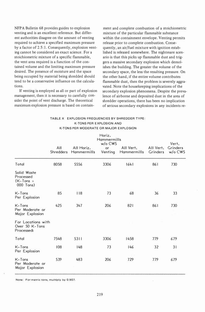
TABLE X EXPLOSION FREQUENCIES BY SHREDDER TY PE:
Total
Solid Waste Processed (K-Tons =
000 Tons)
K- Tons Per Explosion
K-Tons Per Moderate or Major Explosion
For Locations with Over 50 K-Tons Processed:
Total
K- Tons Per Explosion
K- Tons Per Moderate or Major Explosion
K-TONS PER EXPLOSION AND
K-TONS PER MODERATE OR MAJOR EXPLOSION
All All Horiz. Shredders Hammermills
8058 5556
85 118
425 347
7548 5311
108 148
539 483
Horiz. Hammermills
w/o CWS All Vert. or
Venting Hammermills
3306 1641
73 68
206 821
3306 1458
73 146
206 729
Note: For metric tons, multiply by 0.907.
219
Vert. All Vert. Grinders Grinders w/o CWS
861 730
36 33
861 730
779 679
32 31
779 679
ported to date. The possibility does exist, however, and must be considered in venting. Venting to atmosphere is probably preferable, but even here, consideration must be given to arrangements which do not endanger personnel. Also, some venting will necessarily take place through the shredder inlet no matter how large the outside vent may be. Consequently, it should be recognized that shredders will vent to their enclosure space, if any.
CONTAINMENT
The need for inlet and outlet feed openings precludes containment as an explosion management possibility for shredders. The combination of containment and venting requires that attention be given to the relative strength (high) of containment structures compared to that (low) of the relief area.
BUILDING CONSTRUCTION
Damage from shredder explosions can be the result of direct or reflected pressure waves, or they can result from flying objects. Both types of damage should be considered in building design. Pressures at various distances can be at least approximately calculated for given shredder volumes and vent areas. Walls, floors, roofs and glazing should be at least adequate for the calculated pressures. In addition, it is advisable to provide a generous venting panel designed to relief to a safe point by failure at a lower pressure.
In some cases, flying objects can be contained by blast mats. Plywood panels loosely suspended under the floor or roof over the shredders can contain and spread the loading to prevent penetration by thrown objects in these locations. Styrofoam in
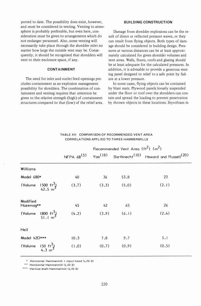
TABLE XII CO MPARISON OF RECO MMENDED VENT AREA
CORRELATIONS APPLIED TO THREE HA MMER MILLS
NFPA 68(5)
Williams
Model 680* 40
(Volume 1500 ft3) (3.n 42.5 m
Modified Hazemag** 45
(Volume 1800 ft3) (4.2) 51.1 m
Heil
Model 420*** 10.3
(Volume 150 ft3) ( I .0) 4.3 m
Recommended Vent Area (ft2) (m2)
Yao ( 18) Bartknecht ( 10) Howard and Russell (20)
36 53.8 23
(3.3) (5.0) (2. 1 )
42 65 26
(3.9) (6.1) (2.4)
7.8 9.7 5.1
(0. n (0.9) (0.5)
• Horizontal Hammermill + input hood (LID 3) Horizontal Hammermill (LID 2) Vertical shaft Hammermill (LID 2)
220
appropriate locations can be used to prevent ricochets. Shatter-resistant plastic glazing should also be considered for control room and other adjacent
windows. Mullions should be adequate to with
stand predicted pressures and the "grip" on the glazing should be deep enough and of proper design to permit the required deflection. A safety bar in
side the mullion can provide extra insurance against the window imploding as a whole in the event of overpressures.
ISOLATIONS
At least until extended operating experience
with the system utilized indicates freedom from explosions, it is desireable that personnel should not be permitted in the vicinity of the shredders during operation.
INERTING
The explosion of all but commercial explosives,
which contain their own oxidant, cannot take place in an inert atmosphere which, for all practical purposes, consists of less than 6 percent oxygen. Although flue gas may normally contain 7-8 percent
oxygen, it greatly reduces the oxygen available to the fuel and will drastically reduce both the frequency and resulting pressure from explosions. There is an additional diluting and cooling factor,
.and, for all practical purposes, inerting with flue gas may provide an effectively inert atmosphere.
Figures 3 and 4 indicate flue gas inerting sys
tems which are contemplated for current applica
tions. They will be push-pull systems in order to
control the pressure in the shredder and will be adjusted to maintain a slight negative internal pres
sure. This should have the additional beneficial effect of reducing the dust in the shredder area.
The shredder is, in a sense, also a fan. There is
an uncertainty as to the flow rate and direction under various conditions of operating and loading.
Consequently, the dribble chute is used as a recircu
lating duct to minimize flue gas requirements.
PRESSURE - BARS
o 0 I 2 20 3 4 5 6 1
< 8 m Z 9 of 10 »" D m 12 » 13 I �14 R115
16
40
60
< 80 m Z 100 of » 120 D m » 140 I
'11 160 of •
I\) 180
0 • -
11 18 19 20 21 22
23
200 • 220
240
260
• 0 0 ... -
,
PRESSURE - PSI
� � � � � -r- '"
l{
�
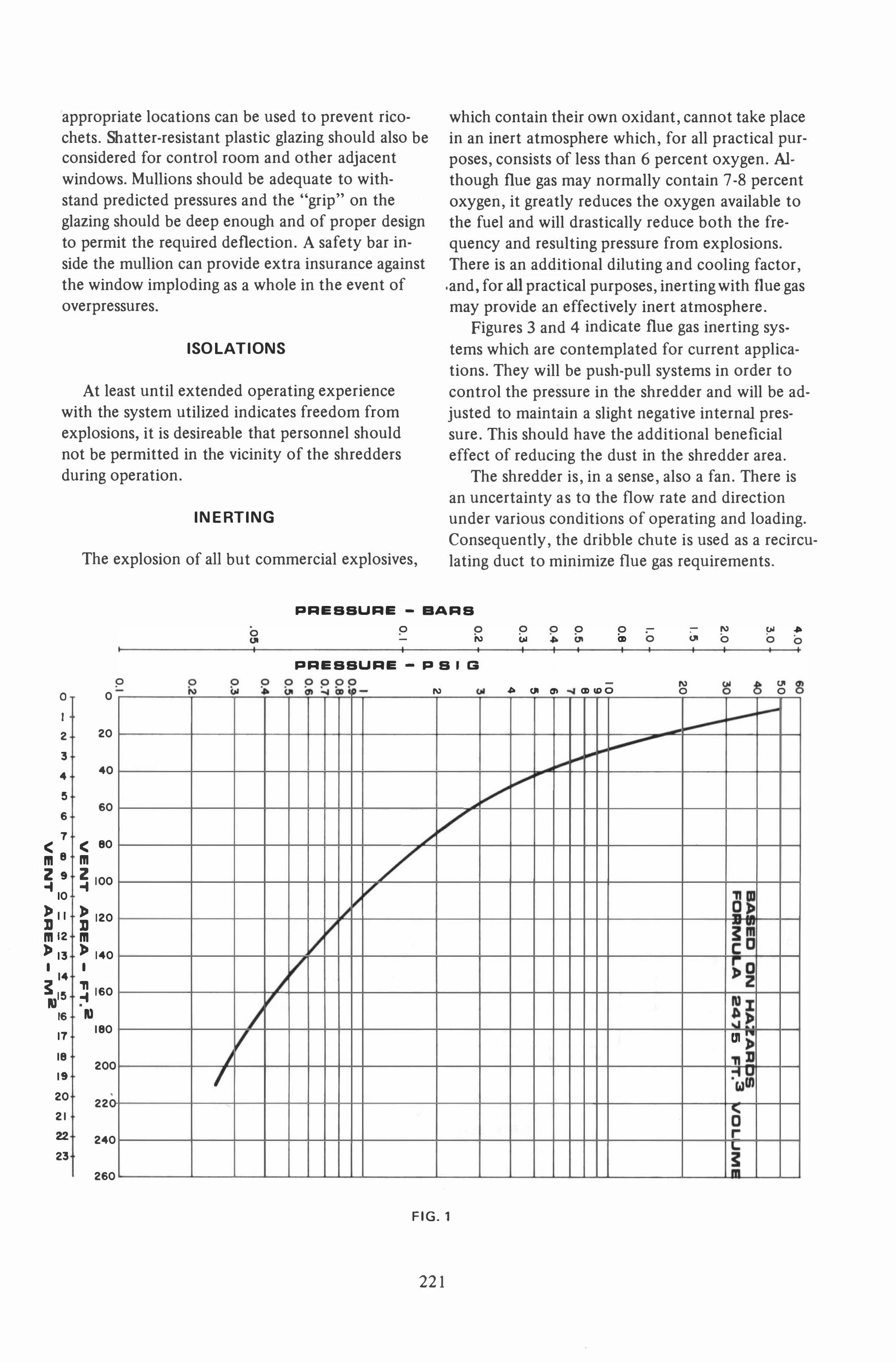
FIG. 1
221
0 '"
I
G
'"
0 0 • '" .,.
,
.. ... en -
;;;r
0 0 -• • • ... <D 0
- '" <D ... O 0
- '" '" .,. • • • .
... 0 0 0 , , I ,
gj 8 uo � 0
�I � til
�

It is important to minimize flue gas requirements, not only to control duct and fan size and horsepower, but also to avoid excessive shredder temperature. Maximum shredder housing temperature limitations of 140 F (60 C) have been suggested. At this point, we are contemplating 325 F (163 C) flue gas for inerting. Temperature limitations of explosion suppression systems must be considered if they are also to be "employed in conjunction with inerting. Some drying will occur with flue gas inerting, but again, caution should be considered to avoid too much drying. With a high volatile fuel like shredded MSW, extreme drying could magnify the possible explosion problems downstream and in storage.
As with venting, the discharge point of the flue gas must be carefully considered. Although it is unlikely that this stream will be carrying its own ignition energy, it will become flammable when ex-
100 30 90
215 80 70
20 eo
50 15
40
� � ..... � ......
� .....
i'. I""t'oo �
posed to additional oxygen. Consequently, release to the atmosphere must be at a safe point, and cleaning will undoubtedly be required. For one application, the discharge will be through the standby oil burners which will release the material into the furnace where controlled ignition will occur when there are flammables in the mixture.
The application and effectiveness of seals at the shredder infeed and outfeed constitute the biggest uncertainties needing further study in the implementation of this approach to explosion management.
EXPLOSION SUPPRESSION
Commercial explosives result in detonations as opposed to the term deflagration as applied to the sudden potentially destructive pressure rise resulting from ignition of an appropriate air/fuel mixture. There is very limited ability to manage de-
OVERPRESSURE VS DISTANCa
..... 1. 1111 L. TN T .au I VAL. NT BHR.DD.R FAILUR. AT BD P8 I
.10 30 lEt ••
I-1-7 • 0
� I' "" � W. • 115 IL
I I
.4 • U U Z5 Z C C l- I-• • -2 -Q Q
• 7
•
!I
..
3
2 ('oj
ci ('oj ci
� ci
1""1'
� "
"\..
''''
� _\.
o N
�
'"
� \
PRESSURE - PSI 0
I I • I III 0 If) 0 d N
PRESSURE - BARS
FIG.2
222
�
IN
o ,.;
r-..
�IC ., T
o •
o on
,
\ \ \ A.�L .CT.C:
o cD
q Q
o �

tonations at this point in time whereas all of the
previously mentioned techniques have successfully been applied to the management of deflagrations.
In addition, the velocity of a deflagration flame front appears to be instantaneous, but, in fact, is slow enough to permit a teclmique called suppres-
•
SlOn.
Effective suppression requires early detection of
pressure rise or other phenomena, very rapid activa-
tion of the suppression system, and high velocity
release of a suppression or inerting agent. Generally,
the suppressant is confined under relatively high
pressure by a rupture disc which is blown by a small
explosive charge similar to a dynamite cap when triggered by the detection system. Among the suppressants which have been effectively employed
in various operations are water, steam, ammonium phosphate and sodium bicarbonate powders and
BOIL.R N-"
I.O.OUTL
B OILERS
...---->0,--- N - a ... N·:I
(280 �) 6000 CFM 325 ° F
(162 °C)
I. O. OUTLETS
(280 �) 6000 CFM 325 ° F
(162°C)
(280 � ) 6000 CFM 3250 F
(162°C)
'------...1....----,-------,-------'--4 1-_____ J CHECK VALVE �.�.J-
( 140 � ) 3000 CFM 1 1/2 H.P. �
(I.I K .W. ) �g COOLING (IF REQUIRED)-::
(35 �) 750 CFM
HIGH TEMP. TRIP -
(175 �) 3750 C.�F:M_�..,.� I H. P.
(.75 KW )
-112 SIG
CHECK VALVE -''''
• CHECK VALVE
(140 � ) 3000 CFM
'-- I 1/2 H. P. '18 (1.1 K.W. ) C '-COOLING (IF REQUIRED)
- 1/2 PSI G
(35 � ) 750 CFM
--·HIGH TEMP. TRIP
(175 �) 3750 CFM
........... - 1 H.P. (.75 KW )
,t" ... --- CHECK VALVE
...--------r---....J'----------..1..----H � -----,
(354 � ) 7500 CFM
(354 �) 7500 CFM
(354 �) 7500 CFM
I I I I
,I \ I I I
BOILER N-" BOIL.R N- II \NINOBOX \NINOBOX
BOIL.R N- :I FUTUR. N- 4 \NINOBOX
FANS TO PRO VIOE PERMISSIVE FOR BHR. OO.R
OAMPERS TO BE INT.RL OCKEO \NITH BOIL.R
FIG. 3 SHREDDER INERTING SCHEMATIC
223

60000 ICFM 21540 �
40000 VFM 1890 �
PANTOGRAPH TYP. ..AL
STACK
-
FIG.4 SHREDDER INERTING SCHEMATIC ALTERNATE
224
1.0. FAN

Halon 1301 and 2402. The burning and pressure rise rates of only
hydrogen and aluminum dust are outside the range of effective suppression with current technology.
Although one authority (Bartknecht) has found water or steam to be more effective than Halon as a suppressant in several applications, at least one leading supplier of suppression systems will not apply their system to refuse shredders unless they are used in conjunction with Halon 1301 as the suppressant. Halon 1301 currently costs $5.00/1b ($11.00/kg) with approximately 240 Ib (109 kg) consumed in each activation. To this must be added the cost of replacing the rupture discs and any service required which can bring the cost of each incident to a reported cost of $2400.00 to $4000.00. ConSidering the probability of four controlled incidents for every one incident which would be observed under controlled conditions, a 1000 tons per day (907 t/day) installation could expect one discharge every 20 days on the average, or 18 per year. On the surface, an expenditure of possibly $80,000.00/year to prevent $25,000.00 + damage every 1.2 years does not appear to be a good tradeoff; but the risk of injury to personnel, more extensive damage, and downtime must also be considered.
In some instances, the supplier of explosion suppression equipment requires that it be serviced exclusively with his representatives' personnel. Service is guaranteed to be available within 24 hr of notice. The benefits of adequately trained service personnel and the costs are not really consequential in view of the additional protection provided. However, the loss of equipment availability can be a serious matter. So far as we are aware, the only instances of explosions on systems properly protected with explosion suppressing systems have occurred when the operators elected to resume shredding prior to recharging the suppressors. Consequently, we believe it important to pursue systems which can and will be rapidly recharged by the normal plant personnal and/or improve service arrangements to result in no more than a few hours down time.
Normal maintenance of the equipment is also of vital importance. Instances have been reported where plugging of the sensors prevented proper actuation of the systems. Newer systems use air or flue gas to purge sensor ports. With the latter, temperatures must be kept within limits specified by the sensor manufacturer.
The use of explosion suppression equipment
can buy additional assurance, but it cannot buy insurance.
WATER SPRAYS
Continuous water sprays have been applied to shredders in a few cases with apparently considerable success in reducing the frequency and severity of explosions. In addition to the potential nuisance problems, this method is not desirable where fuel or energy recovery is contemplated. Accordingly, no further discussion will be given to this method at this time.
EXPLOSIVE DETECTORS
Detectors are available for flammable vapors and can be applied to shredder hoods for intermittent water or steam spray or pre-activation of vents or suppression systems. Work is also progressing on explosion detectors and it is possible that there may be limited beneficial applications for such devices in the future to detect commercial explosives.
CON CLUSIONS
Solid waste shredders inherently have explosion potential and data on explosion experience is increasingly being accumulated and correlated. Many of the earlier installations appear to have been built with minimal regard for this potential. The basic mechanisms applicable to shredders for explosion management are venting, explosion suppression, and possibly inerting. Design of structures and equipment in the vicinity should consider provisions for minimizing damage from explosions and projectiles. An increasing amount of information is becoming available to the designer to assist in alerting him to the problems and options; however, much remains to be discovered or developed. New designs should increasingly incorporate explosion prevention/management provisions to reduce the severity and frequency of explosions.
REFERENCES
[11 "Solid Waste Shredders, A Survey," NCRR Bul
letin, Fall 1974 , Vol. IV, No.4 .
[2 1 Zalosh, R. G., Wiener, S. A., and Buckley, J. L.,
"Assessment of E xplosion Hazards in Refuse Shredders,"
prepared for ERDA, April 1976.
[31 Zalosh, R. G., "Explosion Protection in Refuse
Shredding," presented at the Fifth National Congress on
Waste Management Technology and Energy and Resource
Recovery, December 1976.
225

(4 ) Bartknecht, W. , "The Course of Gas and Dust
Explosions and Their Control," from Loss Prevention and Safety Promotion in the Process Industry, C. H. Bushman,
ed. 1974.
(5) Catalog No. 73-1, Fike Metal Products Corp.
(6) Bulletin No. MC-215B, Fenwal Inc.
Key Words
Explosion
Refuse
Shredding
226

Discussion by
William D. Robinson
Hammermills, Inc.
Trumbull, Connecticut
Referring to subheadings in the paper:
Experience with Explosions
It is commendable that the author has had the perspicacity to examine the vast experience in the auto shredding industry regarding explosions.
Solid waste processing plant designers might also benefit from investigation of the integrated shredding system design and operating experience in that industry which has closely related requirements for air handling, dust and emissions control, reliability, maintenance and operator protection.
Explosion Relief
As the paper states, there have been no known serious downstream secondary explosions, baghouse fires, etc. to date in solid waste RDF/materials recovery installations.
This is because there are few, if any, plants in continuous operation anywhere near design capacity.
The precautions of prolonged shakedown-retrofit status likely account for this.
To this discussor, the design shortcomings of most existing plants are notable.
Also, it is apparent that most if not all serious episodes of shredder explosions have occurred in topfeed mills with the usual hood superstructure configuration.
This leads to a conclusion consonant with the author's observation:
"The greater the volume of the secondary space, the less the resulting pressure. On the other hand, if the entire volume contributes flammable dust, then the problem is severely aggravated. " The latter factor is more critical and of &reater
concern to this observer than any higher volumelower pressure advantage or the recompression phenomenon.
Despite disagreement amongst investigators over pressure relief (venting) design criteria, there is a consensus that adequate pressure relief is paramount throughout the system as the author indicates. Within limits of structural deficiencies and/or excessive leakage, "more is better" might be axiomatic.
227
Continuous purging with an induced air stream can be effective, but present designs are mostly inadequate with regard to volumes and velocity.
likewise, the penchant for recirculating increasingly concentrated dust laden air can be a dangerous practice.
Water Spray
The author's comment is entirely valid, but I would not dismiss the concept summarily.
It appears that a highly atomized mist or fog (say 300 psi header press) can be an effective suppressant without perhaps adding excessive moisture to an RDF product (approx. 1 percent for 50 toni hr @2-3 gpm). Further investigation is certainly warranted.
Inerting
With combustion flue gas as the medium, careful gas temperature control is imperative, - not only to prevent an excessive drying-fire possibility as the author states, but also because:
• High temperature (over 400 F) can significantly increase shredder wear parts maintenance.
• A dew point-HC1, corrosion possibility may exist in the shredder-process circuit if 100 percent firing of RDF with a high plastic content.
DISCUSSOR'S CONCLUSION
The author is to be commended for discussing a sensitive and vital subject forthrightly. He is in the fortuitous position of investigating critical refuse shredder phenomena with a following opportunity to put his ideas into practice.
AUTHOR'S REPLY
To William D. Robinson
Continuous purging would result in dilution, one of the available techniques which could conceivably holq the concentration of flammables below limits of flammability. It would be reasonable to expect this to have considerable effect at least on the smaller volumes of liquids received by the shredder. On the other hand, duct work, clean-up systems, etc. would contribute to the contained volume. Additional attention would be necessary to proper relief from such or the seriousness of

major incidents could well be aggravated. It is agreed that water spray shQWS promise and
possibly may not be incompatible with shredding for fuel processes.
For inerting to be compatible with temperature and other practical considerations, the flue gas quantity must be limited. This requires effective curtaining of the shredder. One important aspect for this to be effective is to use the dribble chute as a recirculation duct in order that the flue gas
228
quantity does not have to be so large as to overcorrie the inherent windage characteristics of the shredder. This was a necessary consideration for the feasibility of incorporating inerting in the Akron project even for test purposes. Limiting the required flue gas quantities to the minimum necessary for inerting also can make chemical treatment practical in the event that corrosion problems should be experienced.