the te-chnical journal of the television -radio trade
TRANSCRIPT

DECEMBER, 1956
THE TE-CHNICAL JOURNAL OF THE TELEVISION -RADIO TRADE
Aural Silent Monitor
Integra; ovc-operated alarm circuit in automatic Conelrad monitoring system.
See circuit analysis, this Issue
Aural
Relay Control 6AU6
Silent
°Reset
Time Increase
tiVS SZ
`533tb t MO1dWOd 3Nv, A3Ii11rV1D 3S1111l t;
Conelrad Alarm
Red
www.americanradiohistory.com

EYerything You Need for Profitable Rotor Sales
cliii r
ave i4
CORNELL-DUBILIER NFIELD,N. J
N p,11014
eOW31S N(Ot1R
TO MORE SALES
need ...whatever model for every Rotor that
a there is
application best! the situation meets the
The greatest coverage and
concentration onCenfiration of f
minute spot
announcemenisonleading
fns in ,pr
majorrotor market
is
working forYOUre-selling
Yovrc
CLEVELAND 13. OHI
www.americanradiohistory.com

PC -151
12 3 4 56 7
PC -150
12 345671
II
ir-e?/6*-6//
Write for free P. E. C.*
Guide No. 3. Lists 130
radio and TV manu- facturers and the
P. E. C. applications.
PC -1697
Cen ab Packaged Electronic
R> Rated first in their class (preferred 6 to 1) in an independent survey of 3,500 electronics -components users.
R More than 60,000,000 now in use - is growing every day!
The industry's most complete line 45 different types, for the jobber m
and the number
- Centralab stocks arket.
YA402-002A
3 1 2 i'C-179 2 3
Circuits
R> Listed in Sam's Photofacts and Counterfacts.
Use the line that's proven - Centralab Packaged Electronic Cir-
cuits. Ask your CRL distributor-or write Centralab, A Division
of Globe -Union Inc., 934L E. Keefe Avenue, Milwaukee 1, Wis.
Y-569 'Trademark
PC 110
2 3 4
PC -177
2 34
C-80
2 3
YA400-001A
1 2 3 4
SERVICE_ DECEMBER, 1956
www.americanradiohistory.com

HO
tub BEST
TO
-
SELEC
utR
- dd YOU
THE
ÿ
P -,s` a iF`" SAS ' the ORIGINAL
$1450 Dlr. Net
TC -1 C. Neat appear- ing, best for tubes. Space inside cover for mirror. Max. cap. 262 tubes. New longer, thinner size 21x15x8 in.
the CARRY -ALL
" .> $1450 Dlr. Net
TC -4. Break -away design gives quick access. Takes tubes or tools easily. Max. cap. 262 tubes. Size 21x15x8 in.
the ADD -A -CADDY IlietbiL
4 AC -1. Snaps firmly on bottom of either TC -1 C
or TC -4. Gives 46% more space, ideal for
$540 tools. All hardware included. Size 21x8x63/a in.
Dlr. Net
b the JUNIOR
$950 Dlr. Net
TC -2A. Same popu- lar features as TC -4
only sA as big. Ideal for quick trips. 153/4x121/2x8 in.
ASK
'Tube Products Largest ing Cases
YOUR
Caddy
Manufacturer
GENOA,
PARTS
is
Co. .
for the
/ /
the Reg. . . originators
Ele=tronic
- `
DISTRIBUTOR
TM
of Tube Technician
COMPANY NOIS
of Argos
Carry- and
PRODUCTS
/// ILL
,
Vol. 25 No. 12
uriuuumr,:miir,e;upurs;uiiie!rtuimuu
DECEMBER, 1956
oirnmu'muul iii ruri:_
The Technical Journal of the Television -Radio Trade
Including RADIO MERCHANDISING and TELEVISION MERCHANDISING. Registered U. S. Patent Office.
COVER CIRCUIT
Conelrad Monitor Alarm System (Ksar Conalert) 20
FEATURES
Editorial Lewis Winner 9
Color -TV Picture Tube Adjustments (Their Relation to Circuits) John T. Jans 10
Electrostatic Speakers (Design-Application-Circuitry) M. E. Swift 13
Tube Tests Plants Use To Gage Performance in Critical TV Applications Earl G. Bond 14
This Month in SERVICE 16
The Care and Feeding of Packaged Electronic Circuits Bruce E. Vinkemulder 18
Conelrad Radio -Alert Receiving System (Cover ... With Complete Circuit: Service Engineering) Norman C. Helwig 20
Printed -Wiring Board Repair (Servicing Helps)
Flyback Transformer-Width Coil-AGC-AFC Troubleshooting Chart Jesse Dines 26
Closed -Circuit Applications Using Community -TV Systems 28
Annual Index to SERVICE: Jan. -Dec. 1956 30
Sound -System Acoustic Efficiency Checks; Stepping Up 1-2 Tube Phono
Amp Output (Audio Report)
CIRCUIT DIAGRAMS
25
33
Electrostatic Speaker Equivalent Circuit... 13 Sync Takeoff Couplate 19 Electrostatic Speaker Crossover Network.. 13 Kaar Conalert Monitor (Complete Circuit) 21 Blocking Oscillators 15 Conelrad Monitor in Plant Music System.. 22 Blocking Oscillator Operational Analogy Diode Filter Packaged Electronic Circuit
15 18
Crosley 390 Horizontal Sweep 27
Detector-AVC-AF Pentode Couplate 18 RCA KCS97 Horizontal Sweep-AGC 27
Pentode Detector Couplate 18 Admiral 17XP3 Horizontal Sweep 27 Vertical Integrator Packaged Electronic Magnavox 650 Horizontal Sweep 27
Circuit 18 RCA RS -153 4 -Speed Phono Amp 45
DEPARTMENTS
Association News 24 Instruments 39 Ten Years Ago in tir.R\ irr: 24 Catalogs and Books 40 TV Antenna Developments Latest in Audio 33, 44,
28 45 Personnel 40
Components 38 Tube News 48
Index to Advertisers
t"lire Contents CuprvipW 1956, Bryan Davis Publislrirrp C,r., Inc.
47
Second -Class mail privileges authorized at New York, N. Y.; additional entry at the Post Office, Norwalk, Conn.... Subscription price: $2.00 per year ($5.00 for 3
years) in the U.S.A. and Canada; 25 cents per copy. $3.00 per year in foreign countries; 35 cents per copy.
2 SERVICE, DECEMBER, 1956
www.americanradiohistory.com

E
1IIIIIIIIIIIIIIIIIIIIIIIIIIIIIIIIIIIIIIIIIIIIIIIII
9cYLr.is O
' IIIIIIIIIIIIIIIIIII!I!Illli' Ill llllllllillll
EDITOR and PUBLICATION DIRECTOR
Lewis Winner
Associate Editor: Assistant Editor: Editorial Assistant: Editorial Assistant:
Art Director:
Supervisor, Circuit
David E. Pearsall II Robert D. Wengenroth Arnold Gewirtz Howard Jennings
Anthony R. AIM
Diagrams: Michael D. Bellezza
Editorial Production: Astrid Kelly
CIRCULATION DEPARTMENT
Circulation Manager: A. Goebel
Asst Circulation Mgr.: A. Kiernan
ADVERTISING DEPARTMENT
Advertising Mgr.: Aaron L. Lafer
East-Central Rep.: James C. Munn 2253 Delaware Dr.
Cleveland 6, O. Tel.: ERieview I-1726
Pacific Coast: Leo Sands, Dist. Mgr. 535 Ramona St.
Palo Alto, Ca if. Tel.: DAvenport 5-3716
Published Monthly by Bryan Davis Publishing Company, Inc. 52 Vanderbilt Ave., New York 17, N. Y.
Tel.: MUrray Hill 4-0170
B. S. Davis, Pres. Lewis Winner. Vice-Pres.
-0110.-s
Save servicing time with
Authoritative Technical Publications
on RCA VICTOR
RADIO, PHONO and TV sets
Directories, Guides, and Service Data Books published by RCA-these are
the basic RCA reference works for a technical library you'll depend upon now and in years to come. In these publications you'll find exact replacement parts lists for all RCA Victor home instruments, servicing and alignment in-
structions, and circuit diagrams-all detailed, factory -originated data-much of which cannot be obtained elsewhere.
BOUND VOLUMES OF RCA VICTOR SERVICE DATA
You'll save time and dollars by maintaining a complete file of these handsome, sturdily bound volumes. Here's authori- tative data for rapid, profitable servicing of RCA Victor home instruments. Included are schematic diagrams, wir- ing diagrams, alignment procedures, waveforms, trouble- shooting suggestions, production changes, complete parts lists, top and bottom chassis views, voltage charts, and shop tips. Vol. I (1923-1937) $3.50; Vol. 1V (1947-1948) $6.00; Vol. V (1949) $5.00; Vol. VI (1950) $5.50; Vol. VII (1951) $5.00; Vol. VIII (1952) $5.00.
SERVICE PARTS DIRECTORIES FOR RCA VICTOR TV RECEIVERS
These publications contain schematic diagrams, top and bottom chassis views (except as noted), replace- ment parts lists, a cross reference index between model name and model number, and an index to previous publications. SP -1007-1946 through June 1950 TV receivers (56 models). Does not include chassis views. 75 cents a copy. SP -1014-1950 through 1951 TV receivers (71 modek ). $1.50 a copy. SP -1021-1952 TV receivers (27 models). 50 cents a copy. SP -1028-1953 TV receivers (108 models). Includes Radio-TV combinations. $1.35 a copy. SP -1035-1954 TV receivers (106 models). Includes information on the CT -100 and 21-CT55 color TV receivers and the RP -197 and RP -198 3 -speed rec- ord -changers. $1.25 per copy.
RCA VICTOR TV SERVICE PARTS
8 TUNER PARTS GUIDE
SP -2001 B-Available in December, lists stock numbers of major replace- ment parts for RCA Victor TV sets by receiver -model number and correspond- ing receiver -chassis number. Also listed are stock numbers of tuner -replacement parts for individual tuner -chassis. Cov- ers the years 1946 through 1956. 25 cents per copy.
RCA PHONOGRAPH CARTRIDGE GUIDE
SP-2003B-Lists stock num- bers of RCA cartridges and stylii. Also lists stock num- bers of RCA cartridges and RCA Victor model numbers of record -changers in which they are used. Single copy free on request.
RCA TECHNICAL PUBLICATIONS ON RCA SERVICE PARTS ARE AVAILABLE THROUGH YOUR RCA
TUBE DISTRIBUTOR-OR FROM RCA, COMMERCIAL ENGINEERING, 415 S. 5TH ST., HARRISON, N.J.
el"O RADIO CORPORATION OF AMERICA, HARRISON, N.J. CORPORATION OF HARRISON, N.J. e
SERVICE PARTS
SERVICE, DECEMBER, 1956 3
www.americanradiohistory.com

z
t t
PYRAMID ELECTRIC COMPANY 1445 Hudson Blvd., North Bergen, N. J.
YOU CAN'T ARGUE WITH ACCEPTANCE
The most complete line of twist mount dry electrolytic capacitors
Proven quality, 100% inspected, accurate replacement, prompt delivery
Better than any claims we could make is the unqualified and enthusiastic acceptance by engineers and servicemen alike. These are some of the features on which this acceptance is based: Aluminum containers provide maximum protection against moisture. Low leakage, long shelf life.
Designed for 85° C. operation. Complete with metal and bakelite mounting plates. Easy to mount. Extremely compact-yet highly dependable. Pyra- mid capacitors are listed in Sams' Photofacts and Counterfacts.
www.americanradiohistory.com

High Volume -Low Price TV Lead-in
MILLIONS of lead-ins
need replacing now!
Get your share of the profits
WITH
Federal5 "ALL-STAR" LEAD-IN TEAM
TV SERVICEMEN:
Check your installation records Call or circularize customers Sell better picture reception Replace with Federal Lead-in
The U. S. has approximately 38,000,000 TV sets in operation today. Millions of these sets -installed years ago - require lead-in replacement. These mil- lions of weather-beaten, inefficient lead-ins are a golden opportunity for increased sales. Literally tens of millions of feet of wire are begging to be replaced . - . !
Federal's "All -Star" lead-ins are outstanding ex-
amples of the qualitycontrol, ruggedness and de- pendability built into every foot of Federal cable. Whatever the run requirements or the local condi- tions, there's a Federal type to give TV customers a new high in performance .. - give you extra profits!
Get your share of the big lead-in replacement market ... with Federal's "All -Star" Lead in Team ..."Certified by a World of Research"... through the International Telephone and Telegraph Corporation.
"America's leading producer of solid dielectric cable"
TV -2000
Economical and Efficient TV -1190- 300 -ohm heavy-duty lead-in with 90 mil. web. Has 7/#28 copper strands. Economical and highly effi- cient. Insulated with Federal -devel- oped "silver" polyethylene for long life. Also available in brown.
Another Low-cost Leader TV -2000- 300- ohm dumbbell -shaped lead-in with 55 mil. -web. Has 7/#30 copper strands. A high -value, low- cost type for the average installation. Cinnamon -brown color is protection against ultra-violet.
"Quality -Controlled" TV Lead-in & Cable
Heavy-duty Type
TV -1182 -300 -ohm deluxe type heavy- duty long life lead-in with 7/#28 copper strands, 100 mil. web. Avail- able in "silver" or brown polyethyl- ene. Resists weather, heat, sun. Very low line loss in fringe areas.
Quality plus Economy TV -1184 - 300 -ohm dumbbell -shaped, standard, economy type lead-in with 7/#28 copper strands, 70 mil. web, for urban areas with no unusual condi- tions. Cinnamon -brown color is high- ly effective in resisting ultra-violet.
Rotor Lead-in TV-1188-Rugged, dependable, long - life rotor lead-in. Weather -resistant. Insulated with "silver" vinyl. Three 7 -strand conductors of .0121 AWG soft bare and one conductor of .0121 AWG tinned soft bare.
Community TV Lead-in
Secondary Lead-in 59/U Type - 73 -ohm coaxial lead-in Highly efficient as a Community TV pole -to -house tap -off. Meets all needs wherever a high-grade installation is a must. Ideal for use with unbalanced input TV receivers.
For data on other types, write Dept. D-456
Federal Telephone and Radio Company A Division of INTERNATIONAL TELEPHONE AND TELEGRAPH CORPORATION
COMPONENTS DIVISION 100 KINGSLAND ROAD CLIFTON, N, J.
to Canada: Standard Telephones and Cables Mfg. Co. (Canada) Ltd., Montreal, P. Q.
Export Distributors: International Standard Electric Corp., 67 Broad St., New York
SERVICE, DECEMBER, 1956 5
www.americanradiohistory.com

S-1256
For safe electrical protection - and the elimination of needless blows, rely on BUSS FUSES .. .
When elec.rizal fallt= occur, BUSS fuses Dpen and clear the circuit. The danger of damage toegLir .Went is reduced to a minimum.
Yet. BUSS fuses are designed and engineer( d s) they won t :low needlessly. When you eep:ace a flown fuse with a
Fusetron or BUSS fuse, your custmners are protected against useless, irrit sting shutdawr.s-and you avoid costly, -ime-
wasting cal3acks.
By =e1ing or. BUS: br all your fuse
needs ... youn help safeguard against loss of castz:ner gooc .:ill and crostly
troubles.
In sales and service, profit by the BUSS trademark
Mitions u>Fcn milicss cf BUSS fuses
for he me, industry arc automotive use
have firmly establ:std BUSS as the Known brans. Hand in.quality products, like BUSS ft -ses, he fou nnaintain your reputation for cLality End service.
Be sure to get . he la est Mf ormation on BUSS one FUSETBON small dirzensior fuses crd juseholders ... Wri:e for It.11etir. SFB.
BUSSMANN MFG. CO. (Div htcdrav f1-ctr, Co.)
Uni.ersity ct Jefferson St Louis 7, Mo.
Ma<ers of a complete Hie of fuses for home, fare,
.arnmercial, :lectronic, cutomotive and industrial u.e.
lEE1F0
6 SERVICE, DECEMBER, 1956
www.americanradiohistory.com

keep operating temperatures down-dependability up!
RCA SELENIUM RECTIFIERS utilize modern design- full surface ventilation with no chance of center -core hot -spots. Note the corrugated spring -steel separators which provide positive multiple -area contacts with each plate. This open construction facilitates free -flow of air and efficient cooling of the plates, and mini- mizes the possibilities of overheated components in compact TV, radio, and phonograph designs.
The one-piece assembly -yoke with the molded mounting stud prevents twisting or squeezing the stack during installation. Rigid construction minimizes the possibility of "barrier" breakdowns-gives greater assurance of dependability in operation.
So, when you need a replacement selenium rectifier, ask your distributor for a dependable, long life RCA SELENIUM RECTIFIER. Available now in 12 types, ratings from 65 Ma to 500 Ma.
SELENIUM RECTIFIERS Radio Corporation of America Harrison, N. J.
SERVICE, DECEMBER, 1956 7
www.americanradiohistory.com
another Raytheon FIRST
0
100% INTERCHANGEABLE TV TUBES THAT ELIMINATE SNIVETS*
6DQ6 12DQ6 17DQ6
Thanks to an exclusive new Raytheon fin design,' the Raytheon 6DQ6 is the first TV tube which elim- inates SNIVETS that is 100% interchangeable - will work without special selection. It eliminates borderline performance, too, because its new de- sign gives it additional and improved sweep char- acteristics not available in ordinary types.
Raytheon 6DQ6 tubes provide SNIVET free per- formance because they are individually tested for deflection operation and are given special tests under sweep amplifier conditions. Raytheon 12DQ6 and 17DQ6 Tubes incorporate this same fin construction and will provide the same supe- rior, trouble -free performance.
`HEY'RE R/C
Nl
`r aV1NEor:. ,sw
4.0£,
AND 51G
An added bonus from the Raytheon 6DQ6 is that its interchangeability simplifies stocking. (It's an improved replacement for 6CU6 and 6BQ6GA series.)
Finally, the Raytheon 6DQ6 is another outstand- ing example of how Raytheon's superior engineer- ing skill and production know-how have brought you still another tube that is first and finest in the field.
44. SNIVET -a vertical disturbance on
the right hand area of the screen.
- --_
RAYTH EON MANUFACTURING COMPANY Receiving and Cathode Ray Tube Operations
Newton, Mass. Chicago, Ill. Atlanta, Ga. Los Angeles, Calif. Raytheon makes Receiving and Picture Tubes, Reliable Subminiature and Miniature Tubes,
all these )C Semiconductor Diodes and Transistors, Nucleonic Tubes, Microwave Tubes.
RAYTHEON
excel/twee in eleoluniw
8 SERVICE, DECEMBER, 1956
www.americanradiohistory.com

1111111111111111IIIIIIIIIIIIII1111111111111111111111111I SERVICE IIIIIIIIIIIIIIIIIIIIIIIIIIIIIIIIIIIIIIIIIIIIIIIIIIIIIiI;
The Technical Journal of the Television -Radio Trade
1956 in Review
THIS HAS BEEN a year of outstanding achievements that swelled opportunities for Service Men.
The semi -conductor field flourished with the de- velopment of new types of highly -efficient tran- sistors and the arrival of two new members to the family; selenium and silicon diodes.
An experimental item for years, the transistor attained a record production of 13 -million units this year, compared with 3.6 -million in '55. Transis- tor -equipped portables were produced in quantity for the first time, numbering about 900,000. A growing number of phono manufacturers began using transistorized amplifiers. The introduction of power transistors, capable of handling large loads, made it possible to include them not only in push- pull amplifiers, but in B supplies for auto radios.
The increased use of transistors brought about significant changes in not only components and chassis, but in test equipment and installation and repair tools. Parts shrunk in size, printed -wiring designs were evolved for practically all chassis and completely new teams of tools and instruments were created to service the miniaturized models.
The advent of the selenium diode permitted the design of improved horizontal a f c circuits, involv- ing a balanced phase detector with a pair of diodes. With the arrival of the silicon diode, it became pos- sible to build new types of high -voltage circuits for series connections, since no special matching of inverse characteristics was found to be required.
ENORMOUS STRIDES were also made on the tube front. For the 12 -volt auto radios, there appeared tubes that can operate directly off the battery for both A and B power, some types working in con- junction with power transistors. Elsewhere, new types of series -string subminiaturized tubes were developed for the increasingly popular compacted TV chassis used in table and portable models. For the extremely shallow and wider -angle picture tubes (110° types being the latest on deck), tubes were designed to provide the required increased deflection.
TIE PLATED -BOARD not only became a feature of transistor radios, but b -w and color -TV models, too. Most of the major manufacturers announced lines with printed wiring throughout, and as in the transistorized equipment, reduced -size parts be- came a prominent factor. In all instances, it was found necessary not only to design special compo- nents to fit the p -w miniaturized pattern, but to
°See page 18. "See page 28, this issue, for an exclusive' report on the use
of closed-circuit lines in a community -TV system.
note that it would now be necessary to use new - type tools that could be maneuvered in tight areas that prevail in the small p -w chassis.
Recognizing the repair difficulties that could ob- tain in these condensed chassis, if certain circuit - mechanical precautions were not taken, engineers studied the problem carefully and came up with many solutions. Tuners were located topside and large openings were made around the tuner shaft to facilitate local oscillator adjustments. In vertical chassis, the window and mask were made remov- able from the front. Circuit components were grouped in sections. All major test points, tube types and socket numbers were stamped directly on each p -w board. And in several models, the printed boards were made of translucent material to provide a clear tracing of the wiring, without removal of the chassis. These unique repair speed- up features were also worked into quite a few radio and phono models.
One set maker introduced a p -w TV chassis with a number of packaged electronic circuits in not only the audio, but in the video and h -v sections. The repair and test techniques required for this new type of construction are detailed for the first time in this issue.*
COMMERCIAL SOUND also set quite a pace during the year. More mobile and fixed installations were made by more Service Men specializing in sound.
Alert to this trend, manufacturers developed a wide assortment of amplifiers, speakers, cables and microphones for every type of indoor and out- door activity. Both phonos and tape shared the spotlight in the sound drive.
Also IN THE 1956 LIMELIGHT were packaged closed- circuit TV systems. Service Men found a solid mar- ket for these chains among schools, banks, industry and local merchants. All applauded the simplified manner in which on -the -scene live activities could be piped over coax using a small camera, control unit and monitor. * *
COLOR -TV became firmly entrenched during the year, thanks not only to extensive programming, but circuit simplification.
Color chassis no longer demand hours and hours of attention during an installation. In most cases, the only item on the agenda is convergence, and with the streamlined procedures now available, using the proper instruments, this is now a simple operation. INDusTRY DOCKETED an enviable record of accom- plishments during the year; a sparkling record that will be a boon to Service Men during 1957.-L. W.
SERVICE, DECEMBER, 1956 9
www.americanradiohistory.com

COLOR -TV Picture -Tube Adjustments
Center of Deflection With Yoke Too Far Back
Correct Center of Deflectio
3 Guns
Correct Color
Incorrect Color
Beams Pass Through Same Aperture
Screen
FIG. 1: WRONG POSITION of yoke in a color -TV tube. When the yoke is not correctly positioned, a beam near the edge of the screen will not strike the correct
color dot.
To ANY THOROUGHLY -GROUNDED TV Service Man, the color -TV receiver should give no fear. The transition from monochrome to color -TV is not nearly as great as it was from radio to TV several years ago. The already - familiar sections of a color receiver highlight this fact: Tuner, if, sound, video amplifier, sync, scan and high voltage. Ten years ago when most Service Men first had to deal with TV, the only circuits that looked familiar were the power supply and audio amplifier.
The new circuits in color -TV are mainly the color -processing circuits. Here one will find a number of critical alignment adjustments that require skill, the proper equipment, and ex- perience to make.
Analyzing these factors, we find that while there is a familiar look to the scan circuits, they operate under considerably higher stress, because all color picture tubes in use today oper- ate at anode voltages much higher (20-30 kv) than the 15-18 kv used in b -w receivers. Therefore, the hori- zontal -scan circuit must supply not only 50% higher anode voltage, but a correspondingly greater deflection yoke power to scan the color picture
10 SERVICE, DECEMBER, 1956
Slightly Tilted Beam
3 Guns
Purity Magnet Position
Center of Yoke Deflection
W- Purity Magnet Corrects The Beam Tilt
Correct Color
Tilted Beam Strikes Here If Not Corrected
FIG. 2: EFFECT of the purity magnet in a color tube; magnet serves to correct tilt of the beam.
tube with such a high anode voltage. Additionally, most color receivers use the shadow -mask three -gun color pic- ture tube which requires a 2" i -d yoke taking greater deflection power than a standard monochrome yoke. As a result, the Service Man can expect some scan -circuit trouble. Most of the components are of recent develop- ment and therefore subject to possible design failures, in addition to the failures brought on by the extreme power requirements. Servicing these circuits should be relatively easy, however, as the operation is identical to b -w, with only the physical size of the components being different.
All color -TV receivers using the shadow -mask color tube have a characteristic that, while not properly classified as a failure, does greatly influence the picture and therefore the customer's satisfaction with his receiver and with the Service Man's work. That characteristic is: The pic- ture tube must be properly adjusted if a satisfactory picture in either monochrome or color is to be ob- tained. This cannot be stressed too much. Proper set up is all-important. A color picture tube is not difficult to set up, but it does require patience
(Left)
FIG. 3: GEOMETRY of a color tube show- ing that a raster shift of 1" in any direc- tion shifts the beam on the spots .0075', enough to cause color impurity. Mathe- matically, we have the off -center distance AB - 4.24 X raster shift/19.24; the spot shift =.53 X distance AB/15; and the spot shift - 4.24 X .53/15 19.24 Y raster shift
.0078 >' raster shift.
and practice. An improperly -adjusted color receiver will not only cause customer dissatisfaction, but will completely nullify the effects of a well -made circuit repair and an other- wise perfect -operating receiver.
One should spend the greatest effort on a color -TV receiver where the greatest apparent improvement in the receiver operation will be found; that is, the setup and adjustment of the color picture tube itself. The. set owner wants a satisfactory picture in both monochrome and color. On a color receiver, a satisfactory picture can only be produced when all the many controls and adjustments are properly set. Therefore it is essential for the Service Man to acquire a thorough knowledge of each control and adjustment on the color receiver. Such a knowledge can be developed through study, supplemented by ac- tual experience.
On a typical 21" color receiver, some of the adjustments necessary on the picture tube itself are: yoke posi- tioning, purity, static convergence, dynamic convergence, rim magnets and field neutralizing coil. These
Blue
30'
.Blue Convergence Path
11
I Red
Final Convergence Point
Red Convergence Path
Blue Lateral Path Green
30'
Green Convergence Path
RIGHT. FIG. 4: ADJUSTMENT of permanent convergence magnets located in each convergence coil; one can move spots of any given color as shown in this illustration.
www.americanradiohistory.com

And Their Relation to Chassis Circuitry How to Position and Check Yoke, Purity, Static and Dynamic Convergence Controls
And the Rim Magnet and Field Neutralizing Coils to Obtain Best Color Reproduction
by JOHN T. J A N S, Applications Engineer
TV Picture -Tube Division, Sylvania Electric Products, Inc.
make it possible to obtain a white or color blank raster.
In making all of the adjustments, a blank field of a particular color is necessary. To obtain such a field it it necessary to increase the Gl (or brightness control) for the desired color and decrease the brightness of the other two colors. Often the bright- ness controls do not have enough range to produce a bright raster of a single color, so the G0 voltage con- trols may be decreased on the un- desired colors and increased on the color to be observed. Red is the best color to observe when adjusting for purity, as green or blue impurities show more readily as an impurity in red.
Importance of Correct Yoke Position
Because of the geometry of the shadow -mask tube, absolutely correct yoke positioning is necessary for the proper beam to strike the proper color dot. In Fig. 1 is illustrated the fact that when the yoke is too far back, the beams are deflected too far from the face so they do not strike the correct colors. The correct position allows the beam to strike the correct color dot. Lateral yoke motion and tilt must also be correct so that each beam is deflected through relatively the same angle. To position the yoke properly, it should be slid forward and back on the tube neck and tilted until the largest area of a single color raster is one pure color at the center of the tube. Purity adjustment is made next. The purity magnet is very simi- lar to the familiar centering magnet and, in effect, centers the beams so
that they all pass through the center of deflection at the correct point to be deflected and then pass through the mask at the exact angle necessary to strike in the center of a dot. Fig. 2
shows the effect of the purity magnet. The yoke position and purity ad-
justment both move the raster on the face of the picture tube as they im- prove the purity. From the geometry of the tube (Fig. 3) it can be seen that a raster shift of 1" in any direc- tion shifts the beam on the spots .0075". This shift is enough to move the spot from the center of one color,
FIG. 5: RELATIVE POSITION of the electron beam, with respect to a color dot for purity ad- justment for field - neutralizing coil, and for yoke -posi- tion adjustment. Arrows show direc- tion the beam must be moved to strike a single color dot at various points
on the screen.
halfway into the next color and cause color impurity.
Static Convergence Adjustment
Another picture tube component that shifts the raster and with it the spot is the static convergence adjust- ment. On the yoke position and purity adjustments, the three beams are acted on together, and the rasters of
all three beams are moved about the same amount. The guns of the shadow -mask color tube are so made that the convergence -magnet assem- bly fits over a portion of the mount, where the magnetic fields to each gun are isolated from each other. There- fore, the static convergence magnet on each gun can be adjusted to move the raster of that gun alone. Conver- gence is necessary, because the three separate beams are each acted on
differently by the yoke and the three rasters will not overlap in perfect registration, unless some means is
taken to adjust each raster position to
do so. There is some interaction between guns on convergence, with the red and green moving about 10%
FIG. 6: NEED FOR dynamic conver- gence is illustrated in this drawing. Be- cause the distance from the center of deflection to the screen is not con- stant, the beam convergence must vary as the beam moves over the face of the screen.
of the distance the blue moves when using the blue magnet alone.
Use of Dot Generator
To make the convergence adjust- ment easier it is necessary to use a dot generator. Additional color test equipment required are a color -bar generator and 'scope capable of ob- serving the color burst signal with full frequency response.
With the dot generator, a pattern of white dots is shown on the picture tube screen. If the convergence ad- justment is not correct, the dots will be clusters of three colors. By adjust- ing the permanent convergence mag- nets located in each convergence coil, the spots of any given color can be moved in the direction shown in Fig. 4. With three spots moving in three given directions, it is impos- sible to make them always come to one position. Therefore, it is necessary to add another convergence adjust- ment, a blue lateral magnet located near the base between the red and the blue gun. This magnet supplies
(Contiued on page 37)
Center of Yoke Deflection
3 Guns
The Beams of The Three Guns Converge At A
Filed Distance From The Center of Deflection
SERVICE, DECEMBER, 1956 11
www.americanradiohistory.com

No antennas ever made can match the perform- ance and sales appeal of these outstanding Channel Master models. -
howmdn indoor antenna models for VHF or VHF -UHF reception
Smart styling eliminates ugly "rabbit ears." Metro Dyne elec- tronic tuning brings in pictures sharp and clear.
`1! 4.1outdoor antenna
The most powerful antenna ever ----- developed: Highest Gain Top Front -to -Back Ratios Greatest Mechanical Strength.
In every TV reception area Channel Master dealers are racking up new sales records with the most popular TV antennas on the market today. Superior products plus consistent consumer advertising is a double- barrelled profit combination you can't beat. When you feature the Channel Master line you always have that extra selling edge ... that extra PLUS
that means faster turnover ... easier sales ... bigger profits.
Isn't it time you called your Channel Master distributor?
Channel Master's massive national and local advertising program ... establishes you as the local TV au- thority ... is creating loads of new prospects right in your own selling area ... and is opening millions of homes to antenna replacement.
FurNrri send o.a..w.l aster Corp
www.americanradiohistory.com
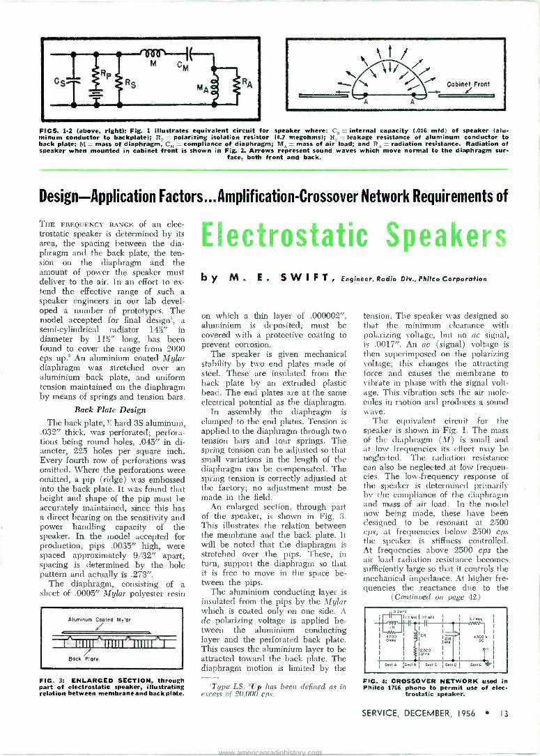
FIGS. 1-2 (above, right): Fig. 1 illustrates equivalent circuit for speaker where: C, = internal capacity (.016 mfd) of speaker (alu- minum conductor to backplate); R, polarizing isolation resistor (4.7 megohms); R = leakage resistance of aluminum conductor to back plate; M = mass of diaphragm, C, = compliance of diaphragm; MA = mass of air load; and RA = radiation resistance. Radiation of speaker when mounted in cabinet front is shown in Fig. 2. Arrows represent sound waves which move normal to the diaphragm sur-
face, both front and back.
Design-Application Factors...Amplification-Crossover Network Requirements of
THE FREQUENCY RANGE of an elec- trostatic speaker is determined by its area, the spacing between the dia- phragm and the back plate, the ten- sion on the diaphragm and the amount of power the speaker must deliver to the air. In an effort to ex- tend the effective range of such a speaker engineers in our lab devel- oped a number of prototypes. The model accepted for final design', a semi -cylindrical radiator 14;x' in diameter by 113i" long, has been found to cover the range from 2000 cps up.' An aluminium coated Mylar diaphragm was stretched over an aluminium back plate, and uniform tension maintained on the diaphragm by means of springs and tension bars.
Back Plate Design
The back plate, 34 hard 3S aluminum, .032" thick, was perforated; perfora- tions being round holes, .045" in di- ameter, 225 holes per square inch. Every fourth row of perforations was omitted. Where the perforations were omitted, a pip (ridge) was embossed into the back plate. It was found that height and shape of the pip must be accurately maintained, since this has a direct bearing on the sensitivity and power handling capacity of the speaker. In the model accepted for production, pips .0035" high, were spaced approximately 9/32" apart; spacing is determined by the hole pattern and actually is .273".
The diaphragm, consisting of a sheet of .0005" Mylar polyester resin
Aluminum Coated Mylar o
I 191 IIIIII 111111 I
Bock Plate
FIG. 3: ENLARGED SECTION, through part of electrostatic speaker, illustrating relation between membrane and back plate.
!IF"!
.f4.eigs Speakeu, by M. E. SWIFT, Engineer, Radio Div., Philco Corporation
on which a thin layer of .000002", aluminium is deposited, must be covered with a protective coating to prevent corrosion.
The speaker is given mechanical stability by two end plates made of steeL These are insulated from the back plate by an extruded plastic bead. The end plates are at the same electrical potential as the diaphragm.
In assembly the diaphragm is clamped to the end plates. Tension is applied to the diaphragm through two tension bars and four springs. The spring tension can be adjusted so that small variations in the length of the diaphragm can be compensated. The spring tension is correctly adjusted at the factory; no adjustment must be made in the field.
An enlarged section, through part of the speaker, is shown in Fig. 3. This illustrates the relation between the membrane and the back plate. It will be noted that the diaphragm is stretched over the pips. These, in turn, support the diaphragm so that it is free to move in the space be- tween the pips.
The aluminium conducting layer is insulated from the pips by the Mylar which is coated only on one side. A dc polarizing voltage is applied be- tween the aluminium conducting layer and the perforated back plate. This causes the aluminium layer to be attracted toward the back plate. The diaphragm motion is limited by the
'Type LS. 'Up has been defined as in excess of 20,000 cps.
tension. The speaker was designed so that the minimum clearance with polarizing voltage, but no ac signal, is .0017". An ac (signal) voltage is then superimposed on the polarizing voltage; this changes the attracting force and causes the membrane to vibrate in phase with the signal volt- age. This vibration sets the air mole- cules in motion and produces a sound wave.
The equivalent circuit for the speaker is shown In Fig. 1. The mass of the diaphragm (M) is small and at low frequencies its effect may be neglected. The radiation resistance can also be neglected at low frequen- cies. The low -frequency response of the speaker is determined primarily by the compliance of the diaphragm and mass of air load. In the model now being made, these have been designed to be resonant at 2500 cps; at frequencies below 2500 cps the speaker is stiffness controlled. At frequencies above 2500 cps the air load radiation resistance becomes sufficiently large so that it controls the mechanical impedance. At higher fre- quencies the reactance due to the
(Continued on page 42)
FIG. 4: CROSSOVER NETWORK used in Philco 1766 phono to permit use of elec-
trostatic speaker.
SERVICE, DECEMBER, 1956 13
www.americanradiohistory.com

TUBE TESTS Plants Use to Gage THE SCIENCE of servicing electronic equipment has reached the point where the Service Man needs to know, as part of his background of technical knowledge, precisely how a chain of tests not only gives birth to a specific tube type, but also in- sures uniformity in production.
In this push-button age, too many tend to over -simplify the problem of testing. It is all too easy in the rush of modern life to assume that a few simple tests, without due regard for the precise applications, will tell all that need be known about an elec- tronic tube. However, a slight va- riation in circuitry, usually not re- produced in a simple test can produce a wide variation in operation.
The many intricate parts and the numerous operations involved in the assembly, sealing, exhausting, and seasoning of a vacuum tube multi- ply the odds against uniformity of a tube type made in mass lots. Yet, this uniformity must be maintained. It is maintained by an extensive series of tests.
The development of test specifica- tions for an electron tube type is in- tegral with the development of the type. Tests are conceived to define the desired characteristics of the tube type. Other tests must be found to define further the characteristics and guarantee the operation of the tube in the applications for which it is in- tended.
To keep abreast of the constantly changing application problems involv- ing the use of electron tubes, an engineering section of our receiving tube department has been detailed to monitor tube usages and keep the factory supplied with the require- ments that must be met in order to satisfy the needs of the industry.
How Tubes Are Developed
A new tube type is brought into being when a set of characteristics is needed that cannot be found in existing tube types. The process by which the tube evolves from a set of desired characteristics to a finished product ready for shipment is, briefly, as follows:
(I) A tube is needed to fill the requirements of a newly de- veloped circuit. The require- ments are written into a Technical Objective as a guide for the design of the new type. Design engineers transform the desired characteristics into actual tubes. Samples are
(2)
LAB TEST set operator testing a 12AX7 miniature twin triode for of noise, microphonics and hum. With this test, spurious signals generated by automatic or hand tapping,. and hum originating within tube, can be measured for amplitude by output meter, and
analyzed by ear with speaker.
made using several variations in design. Due to the many parameters involved in vacu- um tubes, almost any set of characteristics may be ob- tained in several different de- signs. These designs can
(3)
exhibit all the desired char- acteristics to a marvelous degree and still be unaccept- able in actual operation due to seemingly minor differences. One sample lot is accepted by the manufacturer as meet -
70
60
50
40
30
20
10
o
A / /
/ 1 / /
/ / / / Ep 800 VDC
EQiVaried RL 10,000 Ohms / / /
/ / / /
/ i /
i -90 -80 -70 -60 -50 -40
Grid Voltage -30 -20 -10
70
60
50
40
30
20
10
FIG. 1: TRANSFER curves of two sample tubes checked in a specific vertical -sweep application. Although the tubes show very small differences at certain test points, one tube was found to give a linear sweep, while the other produced a top compression that made it unacceptable. Tube whose transfer curve is represented by the solid line
was found acceptable.
14 SERVICE, DECEMBER, 1956
www.americanradiohistory.com

Performance in Critical TV Applications ing the requirements of his developmental circuit and that design is then ready for pro- duction in the factory.
All tube types must pass a number of tests regardless of the intended application. These are the tests that guarantee that the tube will operate as a normal tube. Tests for shorts, opens, leakage, and gas are included in the group. Other tests will fail a tube if the pin strength is not within specified limits, if the glass shows stresses or strains that will cause cracking during the life cycle of the tube, or if the appearance of the tube is spoiled by some blemish even though the tube may be per- fect electrically.
To insure the proper operation of a tube, the electrical characteristics must be guaranteed within tight limits. Test specifications will call for the reading of plate current, transconductance, plate resistance, amplification factor, emission, and any test that may be needed to as- sure acceptance of the tube. It is with the electrical tests that the ap- plication engineer is primarily con- cerned. The questions that must be answered are:
(1) What characteristics are most pertinent to a specific applica- tion, and what limits must be placed upon them?
What are the test conditions that will result in the optimum level of assurance that all
tubes will operate satisfac- torily?
The answers to these questions may be found in the analysis of the cir- cuits involved.
(2)
Vertical -Output Tubes
One application requiring special handling is that of the vertical -output stage. The function of the vertical - output stage is to provide the mag- netic field necessary to deflect the electron beam in the picture tube from the top of the screen to the bot- tom at a rate of 60 cps. This magnetic field is produced by a sawtooth wave- form of current through the yoke. For a given circuit the tube must be able to supply enough current to give full sweep. In addition, the tube
Special Checks Developed by Factory Specialists to
Insure Maximum Efficiency in Vertical Output and
Blocking Oscillator Circuits
by EARL G. BOND, Application Engineer
Receiving Tube Department, General Electric Company
111P111111111111111111..111111111111 II 11 111 111111111111111111111 11.II 1111
must supply this current in such a manner that the sweep will be linear. To utilize the tube at maximum effi- ciency, it will have to be driven from cutoff to zero bias.
In the past it has been common practice to use, as drive voltage for the vertical output stage, the voltage taken across a capacitor charging from B+ or Boost, and discharging through the blocking -oscillator tube or through the normally -off section of a multivibrator. The output stage may be an integral of the multivi- brator circuit.
Once the driving voltage waveform has been defined, the amplitude and shape can be made variable within limits, which are set by the values of the height and linearity controls. We must have tests that will define the transfer curve of the tube. We must guarantee that the curve does not vary (beyond certain limits) from tube to tube, to insure the inter- changeability that is required in mass production techniques employed today. Transfer curves of two sam- ple tubes checked in a specific vertical sweep application are shown in Fig. 1. At certain test points the tubes showed very small differences, yet one tube gave a linear sweep while the other produced a top compression that made it unacceptable. The line- arity control cannot compensate for the compression at the sweep level re- quired. Test points must then be found that will provide tubes that are acceptable. In the case cited the tube
(Right) FIG. 2: TYPICAL BLOCKING oscillator circuit appears in (a); white (b) offers an operational analogy using a switch as the tube and box marked control, that acts in
the same manner as sync and feedback in the oscillator circuit.
1111 .11 II 1111 111111111111.1n
whose transfer curve is represented by the solid line was accepted.
When the tube type has been ac- cepted by a manufacturer for a partic- ular circuit, it is then registered with RETMA and goes into production. New circuts may be made to utilize the characteristics of the tube, but the tube must not stray from the limits that were published.
Let us now analyze the two curves in Fig. 1 to determine why one is acceptable, while the other is not. It must be remembered that these are two triodes submitted as samples for a new circuit. Certainly a circuit can be developed that can use either tube, but the circuit has been de- signed with an eye toward lower costs, no patent infringements, and perhaps even with the thought that
(Continued on page 37)
B+
Boost
fj Output
Charging Capacitor
Sync Switch
V 1
Boost
Charging 'Capacitor
SERVICE, DECEMBER, 1956 15
www.americanradiohistory.com

THIS MONTH IN SERVICE
BUSIEST SERVICE YEAR ON RECORD PREDICTED FOR '57 --Radio-TV replacement parts sales, which rose to $850 -million in '56, are expected to rise to over $1 -billion in '57, a RETMA spokesman forecast recently during a talk before the U. S. Chamber of Commerce in Washington. . . . Radio-TV set servicing costs, estimated at close to $1 -billion for the year, it was said, will also soar during the coming year to a record high of nearly $1,250,000,000.
SERVICE MEN CALLED KEY TO COMMUNITY -TV FUTURE --The future of community antenna TV de- pends largely on the availability of trained Service Men who can install and maintain increasingly complex equipment, NCTA members were told at the recent Portland, Oregon, conference. . It was pointed out that there is an urgent need for Service Men who will advance themselves sufficiently to do a proper job in making the wide assortment of cable gear work. TV Service Men will only be able to carry this added responsibility, conferees were told, if they keep themselves up-to-date in the many specialized skills required; they must expand their knowledge and efficiency by keeping up with current developments. . In a report on the growth of closed-circuit TV, it was noted that there will be a continuing need for community -TV which cannot be fulfilled by the booster type of operation. The booster and translator operations were described as being developed on an unsound economic base, and as a result, their use will be lim- ited to very small areas, where only a cohesive community spirit exists. Added to this, it was said, there are technical difficulties involving ultrahigh operations in the top 13 channels presently allocated to this service. Only when these difficulties are overcome will full use of the translators be achieved.
1 -TUBE CRYSTAL -FILTER COLOR -TV REFERENCE GENERATOR DEVELOPED --At a recent receiver conference in Syracuse, two color experts disclosed that they had designed a single - tube crystal filter circuit for color -TV in which a dual-purpose tube (6AU8 triode - pentode) serves to provide burst gating and amplification. . . . The triode section was said to act as the burst gate device and the pentode as the amplifier. By keying the triode grid with a pulse shaped from the horizontal -flyback pulse and feeding its cathode with chroma from a low -impedance tap on the chroma bandpass filter, which drives the color demodulators, burst gating was said to be accomplished. The stage operates a grounded -grid amplifier for the burst and as such offers a small amount of gain. The pentode, used as the high -gain amplifier following the crystal filter, was noted as giving a gain as high as 175 for weak signals and providing a slight limit- ing action at normal levels. . . . Commenting on circuit performance, the engineers said that no observable hue errors were noted when burst frequency was varied -+-11 cps from its correct frequency. Tests showing this were made with a lab color scanner using a burst generator whose frequency was counted with a digital frequency counter. ...Also, it was noted, spurious responses of the crystal have been controlled so that no colored striations on the picture tube screen are observable. . . . Reference ampli- tude variations were said to be rendered harmless by providing a means for accurately adjusting each synchronous detector to a dc balance.
REPLACEMENT NEEDS FOR TV SETS NO LONGER BEING MADE UNDER STUDY --A concerted study is now underway to determine the quantities of replacement parts and accessories that will be required for eventual use in TV models made by companies who are no longer in business. . The problem of supply for these lines has been found to be acute. . . .
Original replacement stocks of many of the retired manufacturers that were transferred to depots have been depleted and new sources must be built up. Those working on the project believe that it might be necessary to set up a coordinated industry plan to maintain an adequate cross-section inventory of special parts for these halted -pro- duction receivers.
16 SERVICE, DECEMBER, 1956
www.americanradiohistory.com
The Tung -Sol
Distribution Policy
Tung-Sol's resale policy is-and has always
been-firmly based on distribution exclusively
through parts wholesalers who supply the in-
dependent dealer and serviceman.
L. E. COTSEN, Manager, Renewal Sales
RADIO. TELEVISION
SERVICE
TUNG-SOL ELECTRIC INC.
MAKERS OF BLUE CHIP QUALITY TUBES FOR AMERICA'S INDEPENDENT SERVICEMEN
SERVICE, DECEMBER, (956 17
www.americanradiohistory.com

1
I
1
1
M.^JVNAAr
FIG. 1: TYPICAL diode filter packaged electronic circuit.
The Care and Feeding of
Basic PEC Types ... Testing and
ILef,i FINAL TEST stage for packaged electronic components.
... .,..
IN THE FIELD of TV and radio the packaged resistor -capacitor network, known variously as the pec°, packaged electronic circuit or printed circuit, has become a vital member of the component family.
In the months and years to come, Service Men will encounter more and more of these units in their work. One major manufacturer' already has developed a TV chassis whose cir- cuitry consists almost entirely of pack- aged electronic circuit plates; seven- teen have been included. Many other set makers have similar chassis in de- sign or production. Advantages such as space and weight saving, reduction in the number of solder joints, relia- bility and uniformity, and reduction of costs, are such that the long-term outlook is for an ever-increasing use of these components.
Because of this situation, there is a growing need for information about troubleshooting and replacement of these units.
Basically, these units consist of a ceramic or titanate base plate, with resistors, capacitors and wiring printed or mounted thereon, and the whole units protected by a coat or coats of some protective resin. Con- nection to the rest of the circuitry is made by means of several wire or tab leads.
The packaged electronic compo- nents in current use can be divided into six groups; simple resistance - capacitance combinations, triode and pentode couplates, audio detector and
*CIiL trade name. 'Motorola.
FIG. 2 (left, center): PENTODE couplate ,cc that serves as a means of coupling the detector-avc-af and <if output in TV
chassis.
FIG. 3 (left): PENTODE detector couplate circuitry.
pentode detector couplates, vertical integrators, sync takeoff couplates and special circuits.
The simple resistance-capacitance combinations represent the earliest types of pec's produced, and are still widely used today. They usually con- sist of a simple circuit of two or three resistors and capacitors, in series or parallel; resistance and capacitance measurements can be made between available terminals. These units are commonly found in rf filter applica- tions, such as the widely used diode filter in AM receivers. A typical diode filter is shown in Fig. 1.
The triode and pentode couplates contain the basic coupling circuitry between the detector-avc-af tube, (either triode or pentode) and the following audio output tube. This cir- cuit is widely found in TV receivers manufactured since '50. The triode couplate incorporates two resistors and three capacitors, and the pentode couplate incorporates three resistors and three capacitors, as shown in Fig. 2.
In the audio detector and pentode detector couplates we have the same circuitry as the triode and pentode couplates, plus some additional cir- cuitry associated with the detector- avc-af tube. An example of a pen -
FIG. 4: VERTICAL integrator used
to couple the final sync stage to the ver- tical oscillator in TV receivers.
18 SERVICE, DECEMBER, 1956
www.americanradiohistory.com

PACKAGED ELECTRONIC CIRCUITS
Replacement Techniques Used For Each Type
by BRUCE E. VINKEMULDEjt Centrafab
tode detector couplate is illustrated in Fig. 3. Comparison of this circuit with Fig. 2, reveals the presence of an additional capacitor and resistor in the control -grid circuit of the pen- tode, and an additional filter capacitor in the diode circuit of this tube.
Vertical integrators couple the final sync stage to the vertical oscillator stage in TV receivers. The composite sync pulse at the input to this pec is actually a series of about six narrow vertical sync pulses, broken up by horizontal sync pulses of opposite polarity. The purpose of this circuit is to integrate the composite pulse into a single wide vertical pulse of correct polarity. A typical vertical integrator circuit appears in Fig. 4.
The fifth type of pec, the sync takeoff couplate, serves to couple the sync signal, from the point of takeoff in the video amplifier circuit, to the input of the sync amplifier circuit. In addition to the coupling action, these components act as broad bandpass fil- ters, passing the horizontal and verti- cal sync pulses, and attenuating ran- dom signals outside this frequency range which might otherwise trigger the sync circuits. Fig. 5 illustrates a typical sync takeoff circuit.
In addition to the foregoing pec's there are several units which have
O
Sync Arnp (Separator)
0
FIG. S: SYNC TAKEOFF couplate de- signed to couple the sync signal, from the point of takeoff in the video ampli- fier circuit, to the input of the sync
amplifier circuit.
been designed for special applica- tions, and which do not lend them- selves to application groupings at present.
How to Test for a Defective Unit
As in any troubleshooting pro- cedure, the first step is a stage -by - stage check to isolate the defective stage. This can be done either by use of a signal from a strong local sta- tion, or by use of a signal generator, with the antenna disconnected or shorted out.
When the defective stage is lo- cated, it is usually best to check the
(Continued on page 46)
(Above and Below)
TV CHASSIS in which 17 packaged electronic circuits have been iinc sided. Motorola)
SERVICE. DECEMBER, 1956 19
www.americanradiohistory.com

FIELD AND SHOP NOTES
Industrial ... Commercial ... Institutional
Communications ... Audio ... Television Installation ... Maintenance ... Repair
CONELRAD Radio -Alert Receiving Systems Required by FCC:
How Equipment Operates . . Installation -Service
by NORMAN C. HELWIG Kaar Engineering Corp.
Procedures
[See Front Cover]
IF YOU SERVICE two-way mobile radio systems and are responsible for the proper technical operation of one or more radiotelephone systems, then it is your added responsibility to see to it that your customers comply with the new FCC regulations concerning Conelrad,1 the defense technique con- cerning the CONtrol of ELectromab netic RADiations. In the event of the initiation of an alert, all radio stations operating at frequencies below 890 me will be required to cease regular transmissions. Certain broadcasting stations will return to the air on either 640 or 1240 kc and will be operated in such a manner as to render their transmissions ineffectual for navigation or homing by hostile aircraft or missiles.
Although there is some variance in the exact manner in which each class of radio station must comply, the same basic principles apply to all radio stations. It is required and it is also the patriotic duty of every radio station licensee to equip his stations with facilities for the recep- tion of Conelrad radio alerts.
Some classes of radio stations may be permitted to make short duration emergency transmissions during an alert in a manner specifically outlined in applicable FCC rules. No trans- mitter should be operated during an alert unless the operator abides by FCC rules which permit him to do so. Under no circumstances should superfluous transmissions be made even if any transmission is permitted.
Compliance with the requirement for providing acceptable facilities for
Aligning Conelrad monitor with conven- tional AM broadcast receiver test
equipment. (Photo by Cyril Glunk)
the reception of Conelrad alerts may be effected in several manners. Some of the telephone companies offer a Conelrad warning service. The sub- scriber is provided with bell and light signals which are activated from a defense center. However, to re- ceive civil defense information during the alert it n ill he necessary to pro -
'The FCC has requested radio station licensees to comply with these regula- tions on a voluntary basis immediately. Compliance by January 2, 1957 will be mandatory.
Service Men engaged in maintaining two-way equipment should acquaint themselves immediately with the FCC rules and regulations governing the specific classes of radio stations under their supervision. Copies of the rules may be obtained from the Federal Communications Commission, Washing- ton 25, D. C.
vide also a radio receiver which can be tuned to 640 or 1240 kc.
An ordinary AM broadcast receiver may be used as a Conelrad monitor if it is left turned on during the hours that the radio transmitter is used. Such monitoring must be continuous. Before each transmission, the operator in charge must determine by listening to the radio set that an alert is not in effect. However, home radio sets were not designed for 24 -hour per day operation and continuous aural monitoring of a radio program can become tedious, and because of the human element, unreliable.
An outboard alarm circuit, which will obviate the requirement for con- tinuous aural monitoring and which will provide an automatic alarm in case of a Conelrad alert, can be pur- chased or built, which can be wired to a conventional AM broadcast receiver.
The trend at the present time, how- ever, is to install a complete, single - package automatic Conelrad monitor, which provides both an automatic alarm as well as means for reception of civil defense information. The circuit of such a monitor is shown, in part, on the cover and, in complete Form, in Fig. 1.
This monitor contains a superhet receiver which can be set by means of a 5 -position channel selector switch to monitor any of three selected AM broadcasting stations or to provide reception on either 640 or 1240 kc. The receiver contains an integral avc- operated alarm circuit which re- sponds to failure to receive the carrier of the station it is monitoring. It is also designed to fail safe and thus actuates the alarm in the event of any possible failure within the equip- ment itself.
When the alarm circuit is actuated, a red warning lamp on the front panel of the instrument is lighted. A built- in loudspeaker, which is normally silent, is automatically turned on. A pair of relay ccntacts, electrically
(Continued on page 22)
°Kaar Conalert
20 SERVICE, DECEMBER, 1956
www.americanradiohistory.com

Complete Circuit Diagram of Conelrad Radio -Alert Monitor
Lo
Coon
Gnd
TI r -S
Ant 600 i 6 I
J2 Test
Ant
1 C2 I
38 0 Mntd
M
1
C24
C23 O
Ir RI S,Ç
Opaco
AVC
R F G
RF AMP VI
68A6 C5 2CSV -T2 OIs MIA
LI óI00 :06
RS I1300
0-13 :1202
ccssR4 MIA
220 Ohm.
R2 470,000 OMR,
JI AVG
C4
.01
--8 ¡SA ° CCj}Cj
64@40 ysl-0
Channel
L
II
S1 -E
C16
IM20
mfd
B+ 210 V
r- .455Ac 21-
2S 1
_±, J -_. ._- .-
RIO 33,000 13I3
1 OMn. 220 y Ohms
RII 1I7 47C000 C18 C19 C20
Om T d IM
ellMf
I F AMP V3
6BÁ6 95
a 01 Mfd IPZId
e r-
477.000
C21-
433Rc Z2
r 1
I
L
DET 6 1.1 AUDIO V4A V9B
6T8 6A05 95V _2300 T;
JI P- C50
1f 7
33QÓ0 25(000 Ohms Ohms
B+ 2120
R12 C20
-C39 Mld
I Meg
100
Mmfd 1
d100d
. C2
Id
C24 --IF- R19 100,000
1.151 100,000
RIB R20 /I
10 hied 22h000
002 MIA
Volume
RIT 470 Ohm.
AUDIO OUTPUT V5
421 330,
Onora
C27
Mmfd
R22
C26 1000 S Mmtd
Mondor
520_2 5i1
Reset
R23 4700 Ohms
52BóAural
Sllent O
Reset
Alarm Reset
B 235V
A VC V4 C
6T8
R26
530,71a
R2T 10000
Ohms
C33
a Ild
ALARM C35 REGT 100 ALARM
040 "...Mmld AMP
6T8 6AU6
470,000 42V Olen. I
R28
Meg 034
002 MIA
R39 11--NOM-
I00,000 Ohms
R3I 3
OMns
RELAY CONTROL
6ÁU6
150V
R32
:A!
R R3433
4700 2700 Ohm. Ohms
100ROS 00 Ohms
ITimnse
R36 ñ0,000 Ohms
C36 ÿ37 80
fd MN R37
22,000 OM s
- V -
540
External Alarm
- 54B
O
0
Z°- O
C38
ftl
640 B 1240 Ala m Lochout B 235V
Power Input
T9
F 1 Off Pow
I Amp SO
COO x.02 PI
MIA
COO 02 MIA
ó26O VAC
ßßl :260 VAC
RECT VB
6AX5 GT
260V
61 VAC
6I VAC
V4 6111
VS 6005
V6 6AU6
R24 47 Ohres
6AÚ6
3 61306 - -
/2
C3 C32 T15
RIO MIA
LB
res ION
NI 10,000 Ohms
6I VAC
R38 MYNA
10 Ohms
VI 6BÁ6
R25
Ohms
TB 2
econelnd larm
12 Red
LSI
Ohms VC
Ext f Alarm
6.3V Alarm
L Est f Reael
SERVICE, DECEMBER, 1956 21
www.americanradiohistory.com

Conelard Radio -Alert Receiving Systems (Continued front page 20)
accessible at the rear termnial strip, may be used to actuate auxilliary and remote alarms such as lamps, bells, horns, etc. The external alarm is turned off by turning a knob on the panel. The closing of another pair of relay contacts causes 6.3 o to be made available at the terminal strip for operation of an external relay, lamp or other signal.
A 2/ -second delay has been in- corporated in the alarm circuit to reduce the number of false alarms which could be caused by short fail- ures of the station being monitored. If the received carrier is interrupted for more than 2/ seconds, the alarm circuit is tripped. A 250,000 -ohm potentiometer, R.B, is provided on the chassis for adjustment of the amount of time delay. However, this adjust- ment should never be touched unless it has been determined that the time delay circuit is faulty or improperly set.
The external alarm circuits are important since they widen the scope of the applications for such equip- ment. In a typical taxicab radio sta- tion, for example, where the operator and the transmitter are in the same room, the monitor may be set on the operator's desk or on a shelf. Nor- mally, the instrument is silent. It is set to monitor a specific key broad- casting station. It may be necessary to switch from one to another of the three channel switch settings at cer- tain times to conform with the oper- ating hours of the desired stations.
Although the instrument does its monitoring job silently, the operator can flip a switch and listen to the program being broadcast over the monitored station. The monitor must be left on all the time during the hours that the radio station is oper- ated.
In the event of a Conelrad alert,
the red warning lamp automatically lights, and after a few seconds, a 1000 -cycle tone of 15 -seconds dura- tion is heard. The red lamp and the loudspeaker go on automatically and simultaneously; also the external alarm if one is used. After the tone, the broadcasting station will an- nounce the existence of an alert and instruct listeners to tune their radio receivers to 640 or 1240 kc. The radio station operator then would set the channel selector knob on the monitor to either of the two Conelrad frequencies; also the external alarm would be shut off by turning the Ex- ternal Alarm knob to off position.
Of course, the operator must cease radio transmission immediately when the red warning lamp goes on, after advising his mobile units to stay off the air until he advises otherwise. The operators of mobile units are per- mitted to operate their radio trans- mitters only as directed by the base station operator, who is in responsible charge of a specific radiotelephone communications system. Radio si- lence must be maintained until it has been determined that the alert is over or was a false alarm. As men- tioned earlier, some radio stations may be permitted to make short radio transmissions during an alert under some conditions.
To be on the really safe side, it is possible to wire the monitor alarm circuit to the transmitter in such a manner as to disable the transmitter whenever the red lamp glows, thus automatically preventing possible un- lawful transmissions.
If the red lamp goes on and the 1000 -cycle tone and Conelrad alert announcements are not heard, but instead the regular program of the monitored station is heard, it can be assumed that an alert does not exist and that the alarm was actuated by
R2
Aper
h1uI CE/ / ENE Puelm Adde e System
Line to other
dieVotch
O 'Ill M Beu poinb
BI
1__OPdC0 ® Pointc
O 52
KI Si Remote Co ol
Remote Unit \ Linetorronentitter !-y © nffi
Ruer Button
111 ©e Connected in eeriee With peee-fo-tell l ircuit
O
PLANT MUSIC system network designed to ac- commodate a Conelrad moni-
tor.
an interruption of the carrier of 2/ seconds or more in duration or by are intermittent failure in the monitor. However, if the red lamp lights and no sound comes from the loudspeaker within approximately 15 seconds, the operator should set the channel se- lector to another station to determine if an alert exists or if the alarm was tripped inadvertently.
To return to monitoring, once the alarm has been tripped, it is neces- sary to operate a reset switch (S_) which turns off the alarm and si- lences the loudspeaker. An external reset switch can be connected to terminals 1 and 2 on the terminal board (TN through a pair of wires connected at the other end to a normally closed push-button or spring return switch.
In a more elaborate radio station, the monitor can be used to operate an audible alarm, as well as alarms at other points. For example, where a radio station has a remote control point plus one or more dispatch points, the audio output of the moni- tor may be connected so that it will be heard over the radio station con- trol unit loudspeakers at all of the dispatch points when the alarm cir- cuit is tripped. By means of suitable circuits, alarms may be set off at these remote points by the auxilliary alarm relay contacts of the monitor.
FCC regulations require that the operator at the location designated as the remote control point must be able to cut his transmitter off the air and disable all associated dis- patch points. Hence, the monitor should normally be installed at the designated remote control point, where the operator in charge will be able to prevent illegal operation of the transmitter during an alert. How- ever, the existence of an alert should be made known to all dispatch point operators too, and the reception of civil defense information during such an emergency should be extended to all persons whose lives or property may be in jeopardy.
Schools, hospitals, hotels, theatres, police and fire departments, civil de- fense organizations, disaster groups and all places where groups of people assemble should be provided with means for being apprised of a Conel- rad alert and for reception of civil defense information in case of an alert. In many communities, Service Men will be consulted in regard to means for providing Conelrad warn- ings and reception of emergency in- formation. Many organizations will buy Conelrad monitoring equipment from local service shops who will in -
(Continued on page 41)
22 SERVICE, DECEMBER, 1956
www.americanradiohistory.com

u N I VAC® and your stars... What are you shooting for in the vast universe of opportunity? Remington
Rand UNIVAC has a majority of the top men in computer development... men who brought into being the basic knowledge in this field ... who set the
standards others follow ... and who consistently lead in design trends today.
These men will share their know-how wisely with you.
U N IVAC offers permanent positions in Electro -Mechanical Engineering Design Product Design
FIELD LOCATION ENGINEERS with a college degree in a scien-
tific or engineering field and experience in electronics. Extensive
electronic background may substitute for some college. Many op-
portunities for rapid advancement.
FIELD LOCATION TECHNICIANS with technkal school back-
ground and preferably some experience in electroniics. These poi- tions can lead to full engineering responsibility.
® Registered in U. S. Patent Office
Send Complete Resumé to
%d jiWg ArandUt DIVISION OF SPERRY RAND CORPORATION
at any one of these four plant locations D. A. BOWDOIN FRANK KING CAL EOSIN
Dept. PD 28 Dept. ND 28 Dept. YD 28 2300 W. Allegheny Ave. Wilson Avenue 315 Fourth Ave.
Philadelphia, Pa. South Norwalk, Conn. New York City
J. N. WOODBURY, Dept. SD 28, 1902 W. Minnehaha Ave., St. Paul W4, Minn.
www.americanradiohistory.com

STOcKED
TO
not with API's local service and inven- tory facilities solve your ter- minal and tooling stockpiling problems.
API local service and inventory facil- ities stock a wide variety of A MP terminals and tools for your service and maintenance requirements. API inventory and service facilities are as near as your telephone. Call API's nearest branch office for service and expert technical assistance.
In addition to branch offices, API maintains a group of local telephone information centers
for your convenience.
am Trade
dependability 2 ways
The product and the product knowledge
of the API man who serves you.
Omni, ,upee.meexmemweemetemeetfAmen
AMERICAN PAMCOR, INC Subsidiary of AMP INCORPORATED
181 Hillerest Ave., Havertown, Pa. Atlanta, Ga. Philadelphia, Pa. *Baltimore, Md. Boston, Mass. Pittsburgh, Pa. .Portland, Oregon Chicago, Ill. St. Louis, Mo. *Dayton. Ohio Cincinnati, O. San Francisco, Calif*Huntington, W. Va, Cleveland, O. Milwaukee, Wisc. Washington, D.C. Dallas, Texas *Buffalo, N.Y. Knoxville, Tenn. Detroit, Mich. *Indianapolis, Ind. Charlotte, N.C. Hawthorne, Calif. Kansas City, Mo. Minneapolis, Minn. Maplewood, N.J. Albany, N.Y. *Richmond, Va.
*Consult the yellow pages of your local telephone directory under AMERICAN PAMCOR INC., for local telephone center number.
Mark
24 SERVICE, DECEMBER, 1956
Associations TSDA, San Mateo County, Calif.
PRESENTATION OF AN exclusive course in color -TV, de- veloped by San Mateo College, to members of the Television Service Dealers Association, San Mateo County, Calif., has been proposed by the association's training committee.
Plans call for a dual -category course, with classes to begin in January and continue to May. Meetings would be held two nights weekly, with three-hour sessions.
To defray costs to the college, it will be necessary for at least 25 participants to sign up for the course.. Those who sign up will be expected to follow through on the training.
ARTS, Chicago, Ill. A SERIES of technical talks by industry specialists has been announced by the educational committee of Associated Radio and Television Servicemen, Ill.
In a recent lecture on transformers, Robert F. Hodges, Merit sales engineer covered their design, what causes failures, what methods should be used in repairing, re- placing, or making a good substitution when you can- not get the original.
The ARTS color -TV course, conducted during the summer for members, will be resumed in January.
RTSA, Greenville, S. C. FLOYD WINCHESTER has been elected president of the recently formed Radio and TV Service Association in Greenville, South Carolina.
J. B. Cothran, was named vice-president, and R. E. Heath, secretary -treasurer.
As a prerequisite to membership, the new group an- nounced, applicants will have to pass a technical exam now being drawn up.
A grievance committee, which includes a represent- ative of the Chamber of Commerce's Better Business Bureau has been set up.
TRY, Kansas City, Mo. AT A RECENT meeting of the Television and Radio Tech- nician Association, Kansas City, Mo., held in classroom facilities of Central Technical Institute, L. A. Betros of the Institute presented a talk on the theory, application,. and construction of rainbow generators and gray scale indicators.
TEN YEARS AGO IN SERVICE
Boom MARKETS were predicted for TV and FM by govern- ment experts. FCC chairman Charles R. Denny noted that nationwide telecasts, which should be possible within the forthcoming year, would give TV a giant push... Comment- ing on FM, Denny declared that the Commission's long-range program also called for coast -to -coast networking. FM's future looked excellent, he said. . . This enthusiasm from official sources boosted national interest among associations in TV and FM and prompted the development of large-scale clinic and lecture programs by industry specialists on all phases of these new fields... Vacuum tube probes with subminia- ture tubes were introduced.... Fred D. Wilson became gen- eral sales manager of Operadio Manufacturing Co.... The DeMambro Radio Supply Co., Inc., opened a branch in Manchester, N. H.... Frank Folsom, executive vice presi- dent of RCA, received a certificate of appreciation from the War Department. . . . A listing of exact duplicate controls. appeared in the November issue of the Centralab Jobber:. Outlook.
www.americanradiohistory.com

Servicing Helps How to Service Printed -Wiring Boards in Spartan TV Chassis...
u!!u!nuumumu!!!!!m;!!!uum!wu;ora!:!rauu,im!11um!uw!ernuurrAuu ur,amr,rurr,;iuw .
PRINTED WIRING BOARDS, now being used in the Spartan 19 series portable TV chassis, are basically laminated plastic sheets with thin copper foil bonded to one side. To form the necessary wiring, some of the copper foil is removed by a photographic and etching process. Holes are punched in the board through which various component leads are inserted. The leads of standard size components are cut and bent over the copper foil wiring. The wiring side of the board is then dipped in molten solder to make all solder connections at once. The copper foil wiring also picks up solder, thus increasing its ability to carry current. Finally a coat of sili- cone resin varnish is applied to the wiring side of the board to prevent dust or moisture from causing short circuits.
Tools -Materials Required
Although the electrical character- istics are the same as conventional wiring, special techniques are re- quired in servicing these boards. The following tools and material have been found helpful in the repair of the pw boards:
(1)
(2)
(3)
A low -wattage pencil - type soldering iron or soldering gun with a small tip. Solder- ing guns for this work have special angled tips .
A small wire brush, to brush the solder away from a com- ponent to be removed or to brush away the excess solder from a component being sol- dered. Excessive solder can cause shorts or intermittent troubles to occur at a later date.
Low -temperature solder with a rosin core consisting of 60 per cent tin and 40 per cent lead should be used for all solder connections. This solder is fast melting and will provide good conections with little heat.
°Items 2, 5, 6, 7 and 8 are contained in a printed -wiring repair kit marketed by General Cement.
uuiorummiauuumwuumuu!:,ri!muiruuuuumuuumuuuruuuniiiuuumumunum
(4) Diagonal wire cutters and long -nosed pliers to remove defective circuit components.
(5) A thin -bladed knife for prying bent connections when it is necessary to remove the entire component instead of cutting it off at the ends.
(6) A small wire pick or any ob- ject that can be used as a soldering aid. Clear lacquer and brush as a coat of lacquer, to be applied over any repaired area to pre- vent dust or moisture from causing short circuits. A solvent for removal of the silicone resin when effecting the repair of any part of the printed wiring.
(7)
(8)
Replacing P -W Resistors -Capaci rs
If the leads from the defective part are long enough, one should cut the leads where they enter the com- ponent. Then a small loop should be made in each lead of the replacement component. The leads remaining from the defective component should be cleaned, the loops slid over the leads left from the original defective com- ponent and soldered.
When soldering, as little solder and heat as possible should be used; too much heat may cause the original lead to break loose at the printed wiring point.
If the original component does not present sufficient lead length as described, the defective component should be cut in half. After this, each half should be cut away from the lead and usually enough lead length will be obtained to permit a secure connection to the replacement part.
After removal of the defective com- ponent, small particles of solder may be imbedded in the silicone resin. It is necessary to remove these by wiping the board with a clean cloth dipped in the solvent.
Replacing P -W IF Transformers
Soldering iron should be applied to each of the connecting lugs and
(Continued on page 42)
Reach -Twist - Grip -Cut
Easier with Utica Tools®
i For those hard -to -get -at jobs, UTICA'S Long Chain Nose Cutting Pliers will fit the bill. The #654-6 features reachability and cutting power. Cutters are extra hardened by electronic induction to stay factory sharp - longer.
#654-6 with cushion handle
UTICA'S new Transverse End -Cutting pliers with semi -flush edges makes short and easy work of producing clean cuts in confined areas. They are ideal for radio and tele- vision assembly and repair.
#262-5'/s
Firm gripping and twist- ing are sure with this new Needle Nose pliers. UTICA has specially de- signed this pliers with strong, stiff jaws for the Electronic Industry.
#778-6 V2
UTICA® pliers are \ forged of alloy \ steel. Jaws are in- JI duction hardened for greater wear.
r
erieor Utica Drop Forge &Tool Division of Kelsey -Hayes Wheel Co., Utica 4, N.Y.
L
Advertising Dept. Utica Drop Forge & Tool Division of Kelsey -Hayes Wheel Co. Utica 4, N. Y.
Please send me the Utica Tool Catalog.
Name
Address City State J
SERVICE, DECEMBER, 1956 25
www.americanradiohistory.com

Flyback Transformer- Width Coil -A CC Picture Trouble Visual Indication Cause Remedy
Blooming ( excessive height and width, low brightness, poor focus- ing) or complete disap- pearance of raster.
(11
Vertical line; or very narrow picture with blooming, or no picture.
(21
Flyback overheats and burns. If trouble is left uncorrected picture blooms.
(3-41
Ringing; one or a few vertical white lines ap- pearing anywhere on raster.
(51
Narrow picture width with drive line (or black bar) in center.
(61
Hv section of horizontal sweep system checks okeh, but flyback transformer winding is partially or completely shorted and there is corona or arcing in flyback. fSee Fig. 1 and circle 1; Fig. 3, right$1
Flyback transformer should be replaced.
Open, short, or partial -short in low -impedance winding section of flyback transformer. (See circle 2; Fig. 6, right)
Flyback transformer should be replaced.
Short in flyback -transformer coil generates excessive heat causing anti -corona wax to melt. (See Fig. 1 and circle 4; Fig. 5, right$)
Flyback transformer likely cause, especially if mismatched or im- proper air gap is used. Trouble can also be due to low drive, B+ or boost voltages or width coil shocked into oscillation. (See circle 5; Fig. 3, righf$I
Flyback transformer or defective com- ponent should be replaced.
One should check for improper operat- ing voltages and faulty part. A 1000 - ohm resistor should be placed across width or linearity coils.
t0 Faulty or improperly - matched width coil. (See circle 6; Fig. 6, rlghf$)
One should check for faulty component in flyback circuit.
Width coil overheats and burns; if trouble is left uncorrected, picture will bloom.
(71
No picture, narrow pic- ture, or narrow picture with foldover on left.
(81
Reduced picture width; width coil overheats and burns if fault is left un- corrected.
(9)
Defective width coil or flyback transformer; width coil slug all the way out; width coil with lower - than -normal inductance used. (See Fig. 2 and circle 7; Fig. 6, rightI
Shorted (or partially - shorted )
width coil or section of flyback transformer connected to width coil; can also be due to defective capacitor connected across width coil. (See Fig. 2 and circle 8; Fig. 3, right$I
Width coil slug should be readjusted. Defective, or improperly -matched width coil or flyback transformer should be replaced.
Defective width coil, flyback transfor- mer or capacitor should be replaced.
Width coil with lower -than -normal inductance used; core missing from width coil; improperly - matched width coil or flyback transformer; capacitor across width coil is leaky. (See Fig. 2 and circle 9; Fig. 3, right)
Width coil setting should be readjusted, inserting slug, if necessary. Defective width coil or flyback transformer should be replaced; capacitor across width coil should also he replaced.
$Practically any fault or improperly -matched component in the flyback circuit could cause these difficulties; only the likely troubles are detailed. Excessive width, negative pix, split pix and picture hook, caused by troubles in Figs. 4, 5 and 6 circuits (circles 10, 11, 12 and 13) will be analyzed in a subsequent report. *Author of Servicing TV Sweep Systems..
FIGS. 1-6 (right): A TYPICAL flyback transformer is illustrated in Fig. 1, and a width coil in Fig. 2. Horizontal sweep circuit used in Crosley 390 chassis is shown in Fig. 3, while Fig. 4 shows age and horizontal sweep circuits used in RCA KCS97 chassis In, Figs. S and 6 are the horizontal sweep circuits used in Admiral 17XP3 and Magnavox 650 chassis. (Figs. 1 and 2, courtesy Ram.)
26 SERVICE, DECEMBER, 1956
www.americanradiohistory.com

-AFC Troubleshooting Chart by JESSE DINES*
Anti -Corona Terminal Wax (Over Boord Windirg)
.F
Winding
///
Core
..,^""' C hossis
' 1
w
Coi 1
FUrm . 1
Slug
i..\
CoiI
y Core
(Underneath Coil Form)
I B3 1st 0,s 1 F 1 EacT B3 Tc Ist Pa I F Tr nsfon er
Framá Misrrp
` ro
6806 p FI back
Tra,afor mer ~J o r.-\1 1 [ Meg
MIA 13.5KV p ó
500 6AX4 T Mmfd I
1000 op 15,000 Ohms
g (j I/Ji-^.` 001 Ohms Mid 'T,00ó, 6U8 o
O ISO,OIA`1`
Onmf i Onms gGC RECT
6CD6 .' p p
56 Mmfd
Hon
, f' ; IMA 3900
ó e 150 ' Mor 150 00 q'
I
p 3 Yoke 56000 Mmfd (p Mmld _ Yoke ^Mmfd Ohmso o mb
s op
z Mre
1--0 6AU6
7 . Ohms -_-_ é 0700 Ohms
1000 .05 Mid Shielded
Lead AGC
AMPL 33.o0Ó, 56000
Ohms 257V A p Ó1
p
ó wan (-2701
Mm1 é 3300
IMmfd I width ÌMfO 39.000
o330 rn $7$° p ó J
rtco -Lr
20m 00 Ohms
e 9O 't` 330 ;
300V = 00000osin
.IS .I
Mfd TMra
500,000 220,000 Onms
Mmfd
20nmOsO
E-- `Mm 0 m AGc
Dantral
30Jv CO ® CO © ©m m 265V
\'
_ 711.
ftEorackmer I X2 Tra l
Flyboruckm er
I B 3 OTronFI
C 12CU6 ¿ 6CU6
oñ'm: 4 (.esp 1o0
15KV 6AX4
Ha Ohms Mid á
own,
Ohms
4 o4Mta 5
T 47Q000 047Mfa
-®t T1000
5600 r Ohms
^ 150
Mmfd
230
Hor
2200 yoke From MOsc 26DV
p/ o
2130V ' Fr m
gq tl o
2
Widt i AF, 15.000 Ohms H r
Osc 250v
1 /' ?
Boost .OVNÁ
I I , AFC Mfva+agt 6AL5
6AL5 /, Voltage ... 5111,01,
hms PRASE
Bs, Volta
I Mfd
*He-. HORIZ SYNC
DISCR
250,, ® I..047
Onn..
- 13
Mfd 0i© ® T
IB
_Ohms®
DETECTOR
S Supply 3...n SERVICE, DECEMBER, 1956 27
www.americanradiohistory.com

Closed -Circuit Applications Using Community -TV Systems
ANTENNA DIGEST DESIGN APPLICATION
COMMUNITY TELEVISION, often de- scribed as an audio -video communica- tions system, with a given band- width of frequencies and power - handling ability, is not only unique in its technical makeup, but in the varied services it can offer.
Commenting on these unique prop- erties at the recent western NCTA meeting, Fitzroy Kennedy' said that in the community -TV system, we have a cable running throughout a community that is useful over the bandwidth of frequencies of from dc to about 500 mc; an astonishing increase in facility actually installed on poles in many communities over the telephone and telegraph wires whose usefulness extends only to about 3000 cycles.
One might question this broad cov- erage, conferees were told, since there are components of a community - antenna system that put a limitation
INSTALLATION SERVICE
on this type of thinking. There are amplifiers and tapoff devices that are frequency limiting; some have 6 -mc bandwidths and others 200 -mc band- widths. Neither, it was noted, now have enough bandwidth to take full advantage of the cable. But, in tap - off devices, many have a much great- er frequency range than that of the vhf bands.
However, a look into the future re- veals that amplifiers with 330 -mc bandwidths will be available. And in a few years, it was disclosed, am- plifiers of 750 to 1000 -mc bandwidths should be on the scene. Again, one might say that the replacement of amplifiers in existing systems would be prohibitive in cost and defeat the whole idea. There is a solution to this problem. Kennedy said we can
'Chairman of the Board, Spencer - Kennedy Laboratories, Inc.
parallel wide -band amplifiers with existing ones and extend the band- width of the system without ripping out the exisiting equipment. It is true that such equipment is not yet available, but it is feasible to design it because of advances in tube and transistor developments.
Accordingly, we find that the 500 - mc bandwidth system is within the realm of existing techniques, and with almost existing equipment at what appears to be, at this stage, not a prohibitive cost.
Reviewing the possibilities of com- munity systems from not only an en- tertainment, but an educational and industrial point of view, the com- munity -TV specialist said that the coax line network is ideal for teaching purposes.
Through television teaching large bodies of students can be taught by one teacher, (relieving the teacher shortage-and raising the quality of teaching, because more time can be spent preparing for class) and dem- onstrations can be put on where it
was impossible before, because of the cost per class.
Community television fits into this picture, Kennedy said, because com- munity systems are the only economic existing medium that can handle the transmission of educational television information from the originating camera to the classroom. It was noted that every community that has a com- munity antenna system has potentially the means of connecting all school buildings together, so that programs may be originated in one place and transmitted to all other classrooms in the school system. Thus, television has a real contribution to make in in -
(Continued on page 36)
indoor TV antenna said to feature
brass crossed circular phasing bars.
(Picasso Directronic model 8-D; Snyder
Manufacturing Co., Philadelphia, Pa.)
Aluminum trellis -type TV antenna that, it is claimed, is not affected by interference from metal sheathing, insulation, wire screens and appliances. Overall size is 36" wide by 72" high. (Ground -Master; Trio Manufacturing
Co., Griggsville, Ill.)
Antenna using eight twisted aluminum elements arranged in a star pattern on each end of a 34", two-piece aluminum beam. May be used inside, as in attic, or outside. (Starbeam Company, Box
5087, Waco, Texas.)
28 SERVICE, DECEMBER, 1956
www.americanradiohistory.com

DON'T DASS UP PRINTED CIRCUIT REPAIRS!
EVERYTHING YOU NEED IS IN THE...
PRINTED CIRCUIT REPAIR KIT
Now you can repair any printed circuits or printed circuit wiring. This kit contains silicone resin and solvent, pure silver print, solder and tools ... plus the G -C Printed Circuit Service Manual. Used and recommended by leading set manufacturers. Ask for G -C No. 680.
N. 14-2
PRINT KOTE
iiik..e Rorie iKyM.
Ns 53.3
PRINT -SOL SOLVENT
1. ow.
Ciee.i.q b DieeNYkq
Nek 1«e«
680
L CEMEN
GENERAL pR!NTEp'EMEhIT
REPAIR CIR
MFG, c KIT n ROCKFORD, ILIINC)I
qNTq/,ysq//
ND MgTER/q/T /s s/
E THESE G -C CHEMICAL SERVICE AIDS!
U. S. A.
. e I Ii8010 SPPW ' JOR
(41-Ko.,
_ i (19(.414
!
f-.
._l e-
G -C RADIO-TV SERVICE G -C PLI -O -BOND G -C RADIO SERVICE G -C SPRA-KOAT
CEMENT No 30-2 CEMENT No. 43-2 SOLVENT No. 31-2 ACRYLIC SPRAY
No. 8665
GENERAL CEMENT
MFG. CO. Division of Textron Inc.
400 South Wyman Street Rockford, Illinois
G -C DE -OX -ID CONTACT G -C SPRA-KLEEN
CLEANER No. 19-1 CLEAN 8 -LUBRICANT
No. 8666
POLISH .. No. 95-2 RUF-KOAT...No. 60-12 : GENERAL CEMENT MFG. CO.
400 South Wyman Street, Rockford, Illinois
Il Please send me your Printed Circuit Service Manual and G -C
1.1 Catalog. I am enclosing 1Oc (coins or stamps), to cover cost of 111 13
handling and postage.
NAME -
CITY ZONE _STATE
.-_ `, Send 104 for Your G -C Printed Circuit
G Service Manual .. . PLUS G -C CATALOG G
ADDRESS
SERVICE, DECEMBER, 1956 29
www.americanradiohistory.com

ANNUAL INDEX January - December, 1956
ASSOCIATIONS
Association N Jan.-Dec.
AUDIO*
Audio Tran -i rmers for Output Coupling: Their Design and Relation to Circuit. Tubes and Components, and Performance. Jan.
Crossover Networks for M ultiple Speakers. Feb. Electrostatic Speakers; M. E. Swift Dec. IIi-Fi Amps for PA Nov. How to Place . Feed . . Match . .
Phase . Wire Up Speakers in Large Indoor -Outdoor Areas Aug.
Industrial -Commercial Sound System Serv- ice Shops; Oliver Berliner Feb.
Input Transformer Replacement Require- ments Mar.
Installing and Operating On -Location Out- door -Indoor Sound Systems Using Mobile -
Stationary Facilities July Magnetic Recording (Tape Types
Cures for Physical -Electronic Tape De- fects); William I!. Woglom and Lawrence Knees Sept.
Mobile Sound Systems (Equipment -Instal- lation Requirements for In -Motion and Stationary Applications) June
Operation . . Maintenance . . Servicing of Remote -Control System Relays Now Found in Car Radios, Tape Recorders and TV Sets; Lee Scott June
Parasitic Oscillations in Amplifiers: Causes and Cures Apr.
Phasing . Microphone Wiring . Low and Line -Impedance Runs in Large Sound System Installations Sept.
Phono -Tape Repair Tips Nov. Portable Record Player Modifications for
Improved Audio; R. D. Wengenroth Mar. Portable Phono Troubleshooting Mar. Practical Considerations in Magnetic
Recording (How Tape Is Designed and Tested in the Lab and Field . Role of the Recorder in Pickup and Play- back); William H. Woglom and Lawrence Knees Aug.
Probing for Wow and Flutter in Tape Recorders and Phono Players; Leo Sands Apr.
Commercial Mobile Tape -Phono Sound Truck With a Two -Way System Oct.
Selecting Components for Indoor -Outdoor Sound Systems May
Sound -System Installation -Repair on the Pacific Coast; Walter Flagler June
Stepping Up Output in 1- and 2 -Tube Phono Amps . Sound System Acous- tic Efficiency Checks Dec.
Troubleshooting TV -Phono Relays July Vernon Downs Raceway Sound System
(Features Hi-Fi Announce -Music and Intercom Networks); Frederick Hoff man. Oct.
AUTO RADIO
Auto Radio Servicing (Cures for Hash, Microphonism and Hum) Jan.
Chevrolet Corvette Transistorized Car Radio (With Transistor Push -Pull Audio and Blocking -Oscillator B Supply); Frank Hughes May
Field Report on a Small -Town Drive -In Auto -Radio Service Shop; Donald L Govoni Apr.
Highlights of an Auto -Radio Vibrator Evaluation Test -Study to Determine Breakdown Causes and Cures M ty
Search - Tuned Transistor - Powered Car Radio (Design -Repair Analysis of Motor - Control 4 -Watt Tube -Transistor Auto Chassis Powered Directly from 12-V Car Battery); Albert Arnold and Tim Alexander Apr.
Repair -Maintenance of Low -Band 2 -Way Equipment; George W. Vass Jan.
Technical Progress Report on Auto Radios (Comparison of Circuitry, Components and Tubes Used in Car Sets Produced Since the Early '40s); Eli Cohen Apr.
Transistors for Auto Radios Jan. Two -Way System Servicing; George W
Voss Feb. Two -Way 450 -Mc Design -Maintenance;
G. A. Svitek Mar. H -F 2 -Way Receiver Tests; G. A. Svitek Apr. 2 -Way High -Band Installation -Service Tips;
A. R. Sinclair May 2 -Way High -Band Installation Notes; .i. R
Sinclair June Garage -Door Opener Receiver -Transmitter
Circuitry Nov.
BLACK -AND -WHITE TV*
AGC' Systems (A Detailed Circuitry -Tube Analysis Covering Three Types Now in Use: Peak - Average - Keyed) ; J. M Sheehe Aug.
Analysis of Neutralized Triode Circuit UHF -VHF Front End May
Behind the Controls of the 'Scope for B -W and Color -TV Applications; G. S. Ryant.Apr.
Blown Fuses in TV (How to Track Down Fuse Problems Caused by Complete or Intermittent Breakdown of Components); Cyrus Glickstein S^pt.
B -W TV Chassis (CBS -Columbia 3000) 'With Built -In Motorized Tuning Control; J. Roche and R. Teseo Feb.
Curbing Excessive Drive Lines . Cures for Low Brightness, Narrow and Bloom- ing Pictures . . Removing Sync Bars Which Lock in Middle of Picture Jan.
Curbing TVI Caused by Cross Modulation and Other Mixing Effects in TV-Set RF and IF Stages; Harold R. Richman July
Cures for IF Overloading and Vertical Rolling Sept.
Cures for Vertical Instability in TV Chassis; Jack Darr Nov.
Curbing Drift on UHF/VHF Tuners .
Troubleshooting Spurious Modulation Problems Mar.
Damper Tube -Linearity Coil Boost Defects and Remedies; Jesse Dines Aug.
Dual -Selenium Rectifier Horizontal AFC Installation . . . Electrolytic Capacitor Rotation Apr.
Dynamic Diode Discriminator (Improved System of Sound Detection in Philco TV Chassis) ; R. H. Overdeer Oct.
11 -Tube 90° 834 -Inch RCA Portable TV; W. W. Cook Sept.
Flyback Transformer -Width Coil AGC and AFC Troubleshooting Chart; Jesse Dines Dec.
Horizontal Amp Tube Tests; E. H. Nicha us .Aug. How to Boost Low TV Set Voltages; Jesse
Dines Nov. IF Response Curves (How to Interpret
Them . Application During Installa- tion and Repair) ; Robert D. Wengenroth . Jan.
Improving TV Reception in Extreme Fringe Areas Jan.
Multi -Element 600 -Ma Miniatures for B -W and Color TV Jan.
Operation . Maintenance . Servicing of Remote -Control System Relays in TV Sets; Lee Scott June
Replacing Picture Tubes With Aluminized Types Nov.
Remote TV Control Tuning System; Steve Wlasuk and John Fisher Feb.
Report on Keyed AGC Circuitry Used in Old and New TV Chassis; J. M. Sheehe. Oct.
Servicing Printed -Wiring TV Chassis; Alan Lytel Apr.
Servicing RCA TV Portables (How to Re- move Chassis and Make Tuner, Control and Picture -Tube Adjustments) ; W. W Cook Oct.
Setup of Test Equipment Required to Align a TV Receiver Jan.
Stacked Modules Now Being Built Into AC -DC Portables and TV Chassis; Fred Israel May
The Care and Feeding of Packaged Elec- tronic Circuits (Basic PEC Types . . .
Testing and Replacement Techniques That Should Be Used for Each Type) ;
Bruce E. Vinkemulder Dec. Tubes and Circuits Used in AGC Systems;
J. M. Sheehe Sept. Tube Tests Plants Use to Gage Per-
formance in Critical TV Applications (Special Checks Developed by Factory Specialists to Insure Maximum Effi- ciency in Vertical Output and Blocking Oscillator Circuits); Earl G. Bond Dec.
Transistorized Wireless TV Remote Con- trol; Drexel Joh,esou Oct.
Troubleshooting TV Relays Variable AGC Control Hints July
TV Flicker Causes -Remedies . . . Curbing Yoke -to -Width Sleeve Arcing . . . Cures for Christmas Tree Effects Aug.
TV Fuse Installation -Repair (How to Use Fuse Plugs and C (Quick Blow) and N (Slow Blow) Fuses; Cyrus Glickstein Oct.
TV Series -String Tube Types . . . Circuit Classification Feb.
TV Snivets: Causes and Cures; W. O Hamlin June
T V Tube Developments May TV Tuners (Tuning Arrangements, Tubes
and RF Amplifier -Mixer Circuitry); IVayoc S. Rial May
2 -Stage Printed -Wiring Decatron Video System (Philco) With 6AQ5 Power Pentode in Output and 6U8 as First Video Amplifier and Inverter; E. C. Freeland Sept.
UHF/VHF 14 -Inch Portable TV (Hoff- man) With 40 -Mc IF and New Multi- purpose Tubes; E. R. Johns Aug.
Video Lead Dress . . . Localizing HV Problems May
Yoke Problem Service Chart (Streamlined Analysis of Defects and Their Reme- dies); Jesse Dines \far.
CIRCUIT DIAGRAMS WITH ANALYSES
Admiral Selenium Rectifier horizontal Phase Detector Apr.
Admiral 17XP3 Fusible -Resistor Line Sept. Admiral 17XP3 Horizontal Screen Dec. Admiral 21B B -Boost Circuit Jan. Admiral 28YI Color -Chassis Filaments Mar. Admiral 28Y1 Color Receiver (Cover;
Complete Circuit) Mar. Admiral 28Y1 Color System Mar. Admiral 29Z1 Color -TV Chassis (Cover;
Complete Circuit) Nov. Admiral 29Z1 LV Power -Filament Circuit Nov. Admiral 29Z1 Phase Detector Nov. AGC Delay Circuit Oct. Alternate Amp Arrangement for Phase -
Shift Components kpr. Amp -Mike -Tape -Turntable -Speaker Setup at
Raceway Oct. Audio Transistor Circuit with VTVM
Readings Apr. Autotransformer in Antenna Circuit Sept. Average AGC System Sept. Basic Auto Radio Design Changes from
Prewar to Present '\pr. Basic Color/B-W TV Chassis May Block Schematic Illustrating How a Uni-
versal Speaker Transformer Can Be Used to Match a 4 -Ohm Unit with a 16 -Ohm Unit and 16 -Ohm Crossover .Feb.
Boost Circuit With Two 6-V Filament Transformers Nov.
Capacitive Effects in Antenna Sept. CBS -Columbia 3000 B -W TV Chassis
(Cover; Complete Circuit) Feb. CBS -Columbia 3000 Chassis Motorized
Tuning Mechanism Feb. CBS -Columbia 3000 Push -Pull Triode Audio
Amplifier Feb. CBS-Hytron Simplified Tester for Series -
String TV Tubes Mar. Chroma -Luminance Channels July Circuit Illustrating Connection of AC VM
to Determine Horizontal Amplifier Grid Drive Feb.
Circuits for PNP and NPN Transistors Mar. Color/B-W TV Signal Splitter June Color-TV/B-W Signal Paths May Color -TV IF Chain Aug. Correct Method of Installing Color Set in
Existing Multiple B -W Installation Mar. Crosley 390 Horizontal Sweep Dec. Crosley 493 Filament -Wiring Remote
Motor -Control Circuit Oct. Crosley 493 TV Chassis (Cover; Complete
Circuit) Oct. DC V Output Boost Using Power Trans-
former Nov. Decoupling Network Aug. Degaussing Color -Tube Coil June Delco Transistorized Car Radio (Cover;
Complete Circuit) May DuMont RA -340/341 Fused B- Lead Sept. Eico 666 Transistor -Tube Checker Nov. Emerson 120270 Portable Phono Amplifier Mar. 400 -Cps Bass Cut Input July 4 -Speed Portable Record Player Amplifier Dec. Fringe -Area TV -Antenna Distribution Oct. Fused Plug Lines Oct. G.E. Stratopower Horizontal Sweep Aug. G.E. (TV) 21T26 Fused HV Line Sept. G.E. 144.152 Mc Receiver June G.E. Portable Transistor Tester May G.E. 675 and 676 Transistor Radio Revised
Detector Circuits Mar. G.E. ER22A1 450-470 Mc Communications
Receiver Mar. Grid/Cathode Driven Pix Stage Aug. Ifallicrafters D1400D Fused B+ Line Sept. I lickok 660 Color Display Generator June 11i -Fi Bull Horn Raceway Speaker Layout Oct. Hoffman 1144/1144U TV Portable (Cover;
Complete Circuit) Aug. IF Test Alignment Aug. Ignition System With Noise Suppression May Kaar Conelrad Monitor (Complete Circuit) Dec. Keyed AGC System Sept.
30 SERVICE, DECEMBER, 1956
www.americanradiohistory.com

Level -Control Audio Circuit Sept. Load -Compensating Kilovoltmeter Circuit Mar. Magnavox 650 Horizontal Sweep Dec. Modification of Portable Record Player to
Eliminate Phono Amplifier from Circuit. Mar. Modification of Portable Phono Amp to
Feed Separate Amp Mar. Modification of Portable Phono Amp to
Feed Separate Speaker Mar. Module Unit Circuitry May Motorola Auto -Radio Det/AVC/AF Stages;
Model 69MF and 910 Apr. Motorola 6TAS8 Transistor Car Radio
(Cover; Complete Circuit) Apr. Motorola Trigger Circuitry for Search Tun-
ing; Model 69MF Apr. Motorola TV Remote -Control Power Oct. Motorola TK -74 Transistorized Remote
Control (Cover; Complete Circuit) Oct. Motorola TS -95 Color -TV 21 -Inch Chassis
(Cover; Complete Circuit) July Motorola TS -533 Fused -Filament Circuit Sept. Motorola 66L Modular Portable (Complete
Circuit) Aug. 100-V Boost Circuit With 6-V Transf. Nov. Peak AGC System Aug. Pentode Couplate PEC Dec. Pentode Detector Couplate Circuitry Dec. Pentode -Mixer Pentode Tuner May Pentode Output With Feedback Nov. Pentron T-90 Tape Recorder Aug. Perma-Power Garage -Door Opener Re-
ceiver Nov. Perma-Power Garage -Door Opener Trans-
mitter Nov. Phase -Shift Capacitor for Feedback Amp Apr. Philco Decatron Video Circuit (Cover;
Complete Circuit) Sept. Philco Diode System; Simplified Block
Drawing Oct. Philco Dynamic Diode Discriminator Oct. Philco 7100 Universal Color Bar and Dot
Bar Generator Block Diagram Jan. Plant Music System Network Designed to
Accommodate a Conelrad Monitor Dec. PNP Transistor Equivalent Circuitry Apr. Push -Pull Audio Illustrating Parasitic
Oscillation Troubles Apr. Railroad -Radio 2 -Way Test Setup Sept. Raytheon Burst -Gate and Color -Phase De-
tector Circuit Jan. Raytheon Chroma Amplifier Jan. Raytheon Color Killer Circuit Jan. Raytheon Color Set Matrix Network Jan. Raytheon Crystal -Controlled Color Oscil-
lator Circuit Jan. Raytheon T100 Transistor Portable (Com-
plete Circuit) Apr. Raytheon T150 Transistor Portable (Com-
plete Circuit) Apr. Raytheon T-500 Transistor Portable (Com-
plete Circuit) Mar. Raytheon 21C71 21 -Inch Color -TV Chassis
(Cover; Complete Circuit) Jan. RCA Portable RF Tuning Sept. RCA Portable Tube Complement Sept. RCA TV Remote Tuning System (Complete
Circuit) Feb. RCA 21 -Inch Color -TV Power Supply .Oct. RCA CT5A Color TV Chassis (Complete
Circuit) Aug. RCA CTC5 Color -TV Convergence Circuit - Oct. RCA KCS 96-97 Sync Stabilizer Feb. RCA KCS -97 Horizontal -Oscillator and HO
Controlled Plate -Board Unit Apr. RCA KCS 97 Horizontal Sweep-AGC Dec. RCA 630 Horizontal Sweep Aug. RCA 7-TRC-1 Tape Recorder (Complete
Circuit) Sept. RCA 8PT-7030 Portable (Complete Cir-
cuit) Sept. RCP 325 Tube -Transistor Tester May Regulation Tester for Small Dry Batteries .Mar. Relay Bounce 'Scope Check June Remote -Control Mixing Sept. Remote -Relay Circuitry June Resistive Controls in Toasters Nov. Schematic Comparison of Tube -Transistor
Radio Circuitry Mar. 'Scope for B -W and Color -TV Applica-
tions (Complete Circuit) Apr. Selenium Doubler Conversion to Tripler Nov. Sentinel 1U-1202 AC -Line Fusing Sept. Series -Connected Speaker Line Aug. Series -Parallel Speaker Groupings Aug. Single -Ended Output With Feedback -Loop
Adjustments Apr. Six -Horn Switching Array June Small Electrolytic Leakage Test -Forming Nov. Sound Volume -Control Circuit Arrangement
for Connection of RCA Remote Feb. Standard Coil Neutrode Tuner May Special Color -TV Circuitry May Sylvania 1-533-1 Filament -Circuit Fusing Sept. Sylvania 1-534.1 Color -TV Convergence Oct. Sync Takeoff Couplate Dec. Tape Oscillator for Bias -Erase Aug. Thermal Cutout as Line Fuse Sept. Transformer Phasing Test Circuit Nov. Transistor Collector -Current Test Circuit Nov. Transistor Phono, Preamp, Mike Circuits Nov. Triad HF -40 Amplifier Jan. Triode Blocking Vertical Oscillator Nov. Triode -Mixer Cascode Tuner May Tubes Strapped as Triodes Nov. Tube Tester Basic Short -Test Circuit Feb.
Tube Tester Basic Transconductance Test. Feb. Tube Tester Emission Test Circuit Feb. Tube Tester Gas/Grid Emission Test Cir-
cuitry Feb. Tube -Transistor Radios Mar. TV Chassis Horizontal Linearity Section
Circuit Jan. TV Horizontal Amp Stage Aug. TV -Line Amp Fil Adjuster June TV Sound IF Amplifier Circuit Modified
for RCA Remote Control Feb. Twin -Triode Vertical -Oscillator Output Nov. Two -Channel Mixer Sept. Two -Stage Transistorized Audio Amplifier Oct. Two -Way Car Noise Source -Cures June 2 -Way Setup on Diesel Locomotive Aug. Typical Diode Filter PEC Dec. Typical Video IF Amp and Equivalent
Jan. Nov. Nov. Nov.
Circuit Ultra -Linear Amplifier Ultra -Linear Cross -Coupled Amplifier Unity -Coupled Amplifier Variable Damping PA System Nov. Variable Inductance in Antenna Circuit Sept. Vertical Integrator Nov. Vertical Integrator PEC Dec. Video Section of TV Chassis Aug. Westinghouse V2318/2328 Horizontal
Sweep Aug. Westinghouse 2292-1 Color Set (Cover;
Complete Circuit) June \Vestinghouse 2292-1 Color -TV Convergence
Circuit Oct. \Vow -Flutter Test Setups for Tape and
Phono Apr. COLOR -TV*
Admiral Color -TV Chassis With New Phase Detector and Sync Color Killer; John Schumacher Nov.
Antennas, Transmission Lines and Distribu- tion Systems for Color; J. D. Callaghan. Mar.
Behind the Controls of the 'Scope for B -W and Color -TV Applications; G. S. Ryant. Apr.
Circuitry Report on the Admiral Color -TV Receiver (Analysis of Color -Killer and High -Level Demodulator Circuits Used in New Chassis); John Schumacher Mar.
Circuitry Report on RCA 21 -Inch Color -TV Chassis; J. A. May and W. H. Fulroth Oct.
Color -TV IF Amplifiers (Their Function and Service Requirements) ; Steve Wlasuk Aug.
Color -TV Instrumentation (Color Bar -Dot Bar Generators); Walter E. Gilbert Jan.
Color -TV Picture Tube Adjustments; John T. Jans Dec.
Color -TV Picture Tube Developments Apr. Color -TV Receiver Servicing (Based on
Field Experiences iii Chicago Area) ; R. C Janzow June
Installation and Servicing of Color -TV Chassis (Key Circuit Difference in B -W and Color -TV With Which Service Men Should Be Familiar) ; Ken Kleidon May
Motorola 21 -Inch Color -TV Vertical Chassis (With 6BV8 Color-Demodulator/Diffsr- ence Amplification Circuitry) ; Marlin Kroger July
Multi -Element 600 -Ma. Miniatures for B -W and Color -TV Jan.
Raytheon 21 - Inch Vertical Color - TV Chassis; Ken Kleidon Jan.
RCA 21 -Inch Color -TV Chàssis Featuring Printed Wiring Boards; J. A. May and W. H. Fulroth Sept.
Simplified Convergence Adjustment Pro- cedure for Color -TV (Step -by -Step Analysis for Static and Dynamic Con- vergence Control); Ken Kleidon Oct.
Three -Color Transparency Viewer De- veloped to Facilitate Color -Bar Adjust- ments; B. D. Loughlin July
The 'Scope in Color TV Service (General Requirements of 'Scope Response During Color -TV Installation and Repair) ; G. S. Ryant Feh.
Westinghouse 22 -Inch All -Glass Rectangu- lar Picture Tube Color -TV Chassis; Orval H. Jordan June
A White -Dot -Bar Color Display Generator; Robert D. Wengenroth June
COMMERCIAL SOUND Hi-Fi Amps for PA Nov. How to Place . . Feed . Match . .
Phase Wire Up Speakers in Large Indoor -Outdoor Areas Aug.
Industrial -Commercial Sound System Serv- ice Shops; Oliver Berliner Feb.
Installing and Operating On -Location Out- door -Indoor Sound Systems Using Mobile - Stationary Facilities July
Mobile Sound Systems (Equipment -Installa- tion Requirements for In -Motion and Stationary Applications) June
Phasing . . Microphone Wiring . . Low and Line -Impedance Runs in Large Sound System Installations Sept.
A Report on a Commercial Mobile Tape - Phono Sound Truck With a Two -Way System Oct.
eSce Circuit Diagrams, Test Equipment, Tubes.
Selecting Components for Indoor -Outdoor Sound Systems May
Sound -System Installation -Repair on the Pacific Coast; Walter Flagler June
The Vernon Downs Raceway Sound Sys- tem (Features Hi-Fi Announce -Music and Intercom Networks) ; Frederick Hoffman. Oct.
COMMUNITY -TV Closed -Circuit Applications Using Com-
munity -TV Systems Dec. Coax Cables for Community -TV Systems;
Robert Felber Nov. Community -TV Antenna System Main-
tenance June Fringe . Community -TV Antenna In-
stallation Tips Apr. Highlights of FCC Report on Community -
TV Line Radiation Control Aug. NCTA Fifth Annual Convention June A Report on the Fifth Annual Community -
TV Convention July
MONTHLY NEWS REPORTS SERVICE . The National Scene.. Jan. -Apr. This Month in SERVICE May -Dec.
SERVICING HELPS Curbing Excessive Drive Lines . Cures
for Low Brightness, Narrow and Bloom- ing Pictures Removing Sync Bars Which Lock in Middle of Picture . .
Auto Radio Servicing J:v,. Cures for IF Overloading and Vertical
Rolling . . . Checking Magnetic Tools Sept. Drop Compensating Kilovoltmeter (Control
Circuit Permits Accurate Measurement of Very High Voltages Applied to 'Scope); Ronald L. Ives Mar.
Dual -Selenium Rectifier Horizontal AFC' Installation . . . Electrolytic Capacitor Rotation Apr.
A Guide to Basic Tools Needed for Field - Bench Installation -Repair Aug.
How to Service Printed -Wiring Boards in Spartan TV Chassis Dec.
Leakage Control Factors in Bantam Elec- trolytics Used in Transistor Amplifiers Oct.
Parasitic Oscillations in Amplifiers: Causes and Cures Apr.
Replacing Picture Tube With Aluminized Types Nov.
Servicing RCA TV Portables Oct. Troubleshooting TV -Phono Relays .
Variable AGC Control Hints July TV Flicker Causes -Remedies . . . Curbing
Yoke -to -Width Sleeve Arcing ... Cures for Christmas Tree Effects Aug.
TV Fuse Installation -Repair Oct. TV Snivets: Causes and Cures; W. O
Hamlin June Video Lead Dress . Tube Pin Soldering ... Localizing HV Problems May
SERVICE ENGINEERING Checking High -Frequency Communication
Receivers; George A. Svitek Apr. Conelrad Radio -Alert Receiving Systems
Required by FCC: How Equipment Oper- ates . . . Installation and Service Pro- cedures; Norman C. Helwig Dec.
A Field Report on a Mid -West Service Shop With an 11 -Year Record of Progress; R. O. Walton Aug.
A Field Report on a Small -Town Drive -In Auto -Radio Service Shop; Donald L. Govoni Apr.
450 -Mc Equipment Design and Mainte- nance; George A. Svitek Mar.
Garage -Door Opener Installation and Servic- ing; John B. Sevec Sept.
Garage -Door Opener Receiver -Transmitter Circuitry Nov.
Industrial -Commercial Sound System Ser- vice Shops; Oliver Berliner Feb.
Installation Hints . Curbing Noise on 2 -Way High -Band Mobile Systems; A. R. Sinclair June
Radio-TV Plus 2 -Way and Broadcast Equipment Service -Engineering Shop; John T. Wrigley Oct.
Railroad Radio 2 -Way Fixed, Train -Car -on - Person Mobile Equipment -Accessory Ser- vicing; Leo Sands July
Railroad Radio 2 -Way Servicing: Locomo- tive, Power and Antenna Requirements; Leo Sands Aug.
Repair and Maintenance of Low -Band Mobile Communications Equipment; George W. Vass Jan.
A Report on a Commercial Mobile Tape - Phono Sound Truck With a Two -Way System Oct.
Rural Roadside -Shop Servicing in Bothell, Wash. Jack Eichelsdoerfer Jan.
Service Engineering in Sacramento, Calif ;
L. Irl !Wilson Mar. Service Shop With Versatile Installation -
Repair Facilities; Harry R. Caldabaugh.May Sound -System Installation -Repair on the
Pacific Coast; Walter Flagler June Traffic Appliance Servicing (Automatic
Toaster Repair); Milton Wallach Nov. Traffic Appliance Servicing (Essential
(Continued on page 34)
SERVICE, DECEMBER, 1956 31
www.americanradiohistory.com

Ap.EIPHIA
,Vy2-42w -ftw~ed ?
with exclusive interceptor discs
AXiOOA COMPLETE KIT 12 5
Nothing Else to Buy
1 MAST SECTION; 3 WALL STANDOFF INSULATORS
35' TWIN -X CABLE; 1 ADJUSTABLE MOUNTING BASE
ATTENTION TECHNICIANS ! 1st time in electronic history a 1/2 wave length resonant
antenna with only a 1/4 wave length physical dimension.
4 Makes every building contractor a
market for built-in antennas
'I Opens a big replacement market
.J Offers an exclusive "hideaway" in-
stallation
I Handles easily because of light weight
and small she
NI Recommended for METROPOLITA
es andN
SUBURBAN areas within iof
television stations
MANUFACTURING CO. PHILADELPHIA LOS ANGELES TORONTO
32 SERVICE, DECEMBER, 1956
www.americanradiohistory.com

BEFORE A SOUND system is put in, it is good practice to determine the acoustical efficiency of the area in which the installation is to be made. The resultant information provides a valuable guide to speaker and mi- crophone placement and the types and quantity that will be required.
An interesting example of what such tests can reveal appeared in a recent report prepared by a group of audio engineers who checked the acoustics of the Cleveland Public Auditorium.
First the team ran a series of artic- ulation tests by placing several per- sons in various locations throughout the auditorium and reading to them a list of 100 disconnected syllables. The listeners then recorded the syl- lables they heard, or thought they heard, and their lists were then com- pared to the master. The results of the articulation tests revealed that the hall fell well below the accepted criteria.
According to the sound experts, the most important test conducted was that of reverberation.' This test in- dicated the length of time required for various sounds to fall off, thus determining whether the sound lin- gered long enough for its vibrations to become intermingled with later sounds.
The reverberation problem in the hall was found to be the predominant element in its bad acoustics. Once this problem has been eliminated, it was felt, it will reduce greatly any other difficulties arising from echo, frequency of response and loudness.
The tests showed that sounds in the frequencies of 125 to 250 cps had a falloff time of 6;_ seconds. It
H1 -Fi PROJECTOR for indoor and outdoor use. Unit is a two-way divided system, coaxially arranged. In action, an 8" speaker reproduces the frequency range below 2,000 cps. This unit drives a single -fold horn (front loaded design) with a phase inverter bass reflex port near the horn throat. (HF -100 projector; Jensen Mfg. Co., 6601 S. Laramie Ave., Chicago 38, Ill.)
AUDIO INSTALLATION AND SERVICE
Phono Tape PA
Cartridges Needles Amplifiers Speakers
Sound System Acoustic Efficiency Checks .
Output in 1 and 2 -Tube Phono Amps
was found that approximately 37,000 square feet of the auditorium's walls, ceiling or floor will have to be treated acoustically to shorten this extended falloff time to acceptable periods.
Examination Steps
Each area of the wall, ceiling and floor space of the hall was examined to determine what treatment could be applied, and how much of that area was available for treatment. This was necessary since events which are housed in the auditorium are varied and on many occasions the sound does not emanate from the stage. In those events where the center of the hall is the focal point, the reverbera- tion as the sound is repeatedly re- flected from the ceiling and floor is
such that sound is indistinguishable.
Slow Speed Cure
IF A MAGNAVOX-COLLARO changer appears to run slow, one should first remove turntable and check position of neoprene washer inside turntable hub. Slow speed will result if the washer is distorted or is not properly positioned in the groove provided in the turntable hub. Then the turn -
'These tests were conducted with the
aid of a Brush of spectrometer, a high- speed level recorder, a beat -frequency oscillator with a warble tone attach- ment, a condenser microphone and an automatic reverberation time switch.
.. Stepping Up
table shaft should be lubricated with light machine oil.
Tension of idler spring should then be checked. If the turntable carp' be stopped by hand and the motor con- tinues to run, the tension on the idler spring should be increased. If the changer is slightly slow on all speeds it may be necessary to use a larger motor pulley.
Spindle Adapter for 45
A DESIGN CHANGE has been incor- porated in the Magnavox-Collaro 45
(Continued on page 44 )
PHONO REPLACEMENT pickup cera- mic cartridge with minimum needle force of 21/2 grams and a response to 12,000 cps for the Chrysler car phono system. Cartridge, it is said, features a
.003" sapphire stylus. (WC20; Shure Brothers, Inc., 222 Hartrey Ave..
Evanston, Ill.)
SERVICE, DECEMBER, 1956 33
www.americanradiohistory.com

MDF-78 and MDF-80 for exact re- placement in over 200 models and chassis of Motorola-Hoffman- Hallicrafters. Provides exact lead color coding and exact network. Two more in the exact replace- ment line of a company that has always led the industry with the most complete selection of trans- formers, yokes and coils. Merit re- placement parts are actually better than original equipment because Merit is the only manufacturer of transformers, yokes and coils who has complete production facilities for all parts sold under their
i brand name.
MERIT COIL AND TRANSFORMER CORP.
4427 N. CLARK ST., CHICAGO 40, ILLINOIS
Annual Index (Continued from pa2:c 31)
Tools, Test Equipment and Component, Required to Repair Expanding Variety of Small Electrical Appliances; Milton Wallach Aug.
2 -Way High -Band Mobile Installation - Service Tips; A. R. Sinclair May
2 -Way Railroad -Radio Service: Field -Shop Procedures . . Test Equipment . .
How to Get Into the Field; Leo Sºnds Sept. Two -Way System Servicing: Noise Elimina-
tion Filters ... Troubleshooting Receiver - Transmitter Components; George 1V Vass Feb.
SERVICE SHOP FIELD REPORTS
A Field Report on a Mid -West Service Shop With an 11 -Year Record of Progress; R. O. Walton Aug.
A Field Report on a Small -Town Drive -In Auto -Radio Service Shop; Donald L Govoni Apr.
Garage -Door Opener Installation and Ser- vicing; John B. Sevec Sept.
Industrial -Commercial Sound System Ser- vice Shops; Oliver Berliner Feb.
Radio-TV Plus 2-Wav and Broadcast Equipment Service -Engineering Shop; John T. Wrigley Oct.
Rural Roadside -Shop Servicing in Bothell, Wash.; Jack Eichelsdoerfer Jan.
Service Engineering in Sacramento, Calif.; L. Irl Wilson Mar.
Service Shop With Versatile Installation - Repair Facilities; Harry R. Caldabaugh.May
Sound -System Installation -Repair on the Pacific Coast; Walter Fla-nler June
Traffic Appliance Servicing; Milton Wal- lach Aug.
TEST EQUIPMENT ... PROCEDURES
Acceptance Tube Tests tao Minimize Call - hacks June
Behind the Controls of the 'Scope for B -W and Color -TV Applications; G. S. Ryant.Apr.
Checking High -Frequency Communications Receivers; George A. Svitek Apr.
Color -TV Instrumentation (Color Bar -Dot Bar Generators); Walter E. Gilbert Jan.
Drop Compensating Kilovoltmeter; Ronald L. Ives Mar.
Horizontal Amplifier Tube Testing Pro- cedures (Methods Used by Tube Manufac-
turer to Insure Operation in Circuits for Which Tubes Have Been Recommended); Elmer H. Niehaus Aug.
Horizontal Amplifier Tube Tests in the Plant; Elmer H. Niehaus Sept.
IF Response Curves; Robert D. Wengen- roth Jan.
Portable Transistor and Tube -Transistor Testers May
The 'Scope in Color -TV Service; G. S Ryant Feb.
Setup of Test Equipment Required to Align a TV Receiver Jan.
Simplified Convergence Adjustment Pro- cedure for Color -TV (Step -by -Step Analysis for Static and Dynamic Con- vergence Control) ; Ken Kleidon Oct.
Special Tests for Tube Elements; E. A Brausen Nov.
A Technical Report on Tube Testers (De- tailed Analysis of the Four Basic Types and Their Application in the Field and in thr S11, ; Robe,/ D. El'cngeurotI, Feb.
fe «ta' fiwev-
UNIVERSAL
TV TUBE
BRITENER
Does Everything
plyi /TF,f,,
At All Distributors
manufactured by
e fwe COMPANY
4727 N. Damen Avve., Chicago 25, Ill. monufacturers of elect,onic equipment since 1929
Export: SCHEEL INT., Chicago
Testing Tubes for Critical Circuits \lar. Three -Color Transparency Viewer De-
veloped to Facilitate Color -Bar Adjust- ments; B. D. Loughlin July
Transistor -Tube Tester Nov. Troubleshooting Transistorized Radios; Ken
Kleidon Apr. 2 -Way Railroad -Radio Service . . . Test
Equipment; Leo Sands Sept. A White Dot -Bar Color Display Generator;
Robert D. ltien tenrot/n June
TRANSISTORS-TRANSISTORIZED EQUIPMENT
The Chevrolet Corvette Transistorized Car Radio (With Transistor Push -Pull Audio and Blocking Oscillator B Supply) ;
Frank Hughes May Cross -Sectional Views of Transistors,
Sockets and IF and Oscillator Coils Used in Transistor Receiver Mar.
Increasing Sensitivity of All -Transistor Sets Mar.
Leakage Control Factors in Bantam Elec- trolytics Used in Trmisi>te:r :Amplifiers Oct.
SERVICE MEN KNOW THERE IS JUST ONE
HUSH Reg. U.S. Pat. Off.
Chemically engineered for tuners and switching mechanism
Hush comes in a 6 oz. pres- sure can with sufficient pressure to reach all con- tacts to wash -away that dirt, leaving clean and positive contacts, protected with a lasting lubricant film.
$2.25 Hush also avail- able in 2 oz., 8
netcon oz. taaindners.
32 OZ.
EVER -QUIET Rae. U.S. Pat. Off. Pend.
Since 1949 the Original Volume Control and Contact Restorer
EVER -QUIET is a free -flowing liquid that leaves no powder residue. Scientifically designed to seep d the shaft and penetrate the control or po- tentiometer, cleaning the con- tacts and leaving a safe protecting film. Harmless to metals, wire or carbon. Will not affect inductance, capaci- tance or resistance. 2.Ounee Bottle with Handy Dispenser (32 oz. sizes available) only 59c
EVER -QUIET
See your distributor or write to
CHEMICAL ELECTRONIC ENGINEERING, INC. Matawan, New Jersey
34 SERVICE, DECEMBER, 1956
www.americanradiohistory.com

New Source of Income WITH AMAZING
Steam Iron CLEANER
Steam Irons Resale
Need Cleaning
Too! * Removes clogging scale. * Safe odorless easy to use.
* Perfect for hard water areas. * Tested and recommended by appliance manufacturers.
Nationally Advertised in Parents, Living, etc.
OBBERS! Still a tit, choice territories available.
( Full year supply)
ORDER TODAY from your jobber, or write direct for name of nearest dealer.
FAST CHEMICAL PRODUCTS CORP. 65 Page Avenue Yonkers, N. Y.
ask the
"Man -on -the -Roof'' why he prefers
TWO TO A SET
RATCHET TYPE CHIMNEY MOUNT
Model RT ICc lv. Banding) Model RT -ST (Stainless Banding)
FASTEST, SIMPLEST, MOST CONVENIENT EVER
MANUFACTURED Monnts in 2 simple steps. Completely factory assembled with no eyebolts, banding clips. nuts, etc., to handle. Furnished with flat -lay, non -coiling banding. heavy gauge embossed, welded steel construction. Forged, beat treated Alum. ratchets.
Write for NEW 1957 Catalog
SOUTH RIVER METAL PRODUCTS CO., INC.
South River, New Jersey
pioneer &
outstanding producer of finest line of antenna mounts
Transistors for Power, Auto Radio and Portable Uses Jan.
Portable Transistor Testers May A Report on Transistorized Portables
(Complete Review of Circuitry Used in Raytheon Models . Servicing and Test Procedures); Ken Kleidon Mar.
Search - Tuned Transistor - Powered Car Radio; Albert Arnold and Tim Alexander.Apr.
Transistor -Tube Tester Nov. Transistorized Wireless TV Remote Con-
trol; Drexel Johnson Oct. Troubleshooting Transistorized Radio.; Ken
Kleidon Apr.
TUBES*
Acceptance Tube Tests to Minimize Call- backs June
AGC System Tubes; J. M. Sheehe Aug. RCA 21 -Inch Color -TV Chassis; J. A. May
and W. H. Fnlroth Oct. Color -TV Chassis With New Phase Detec-
tor and Sync Color Killer Nov. Color -TV Picture Tube Developments Apr. Complete Circuit Report on 6 -Tube Modu-
lar Portable; Richard J. Harasek Aug. Dual -Selenium Rectifier Horizontal AFC..Apr. Dynamic Diode Discriminator (let. 11 -Tube 90° 8% -Inch RCA Portable TV Sept. Horizontal Amplifier Tube Testing Pro-
cedures Aug.
Horizontal Amplifier Tube Tests in the Plant; Elmer H. Niehaus Sept.
Multi -Element 600 -Ma Miniatures Jzn. Tubes for Series -String TV Use and
Standard Prototypes Feb. Portable Tube -Transistor Testers Ally Replacing Picture Tubes With Aluminized
Types Nov. Special Tests for Tube Elements; E. A.
Bra nr en Nov. A Technical Report on Tube Testers Feb. Testing Tubes for Critical Circuits \Iar. Transistor -Tube Tester Nov. Tube News Tube Pin Soldering Tubes Used in AGC Systems
-kin -Dec. May Sept.
TV-Auto Radio Tube Developments Sept. TV Series -String Tube Types . . . Circuit
Classification Feb. 2 -Stage Printed -Wiring Decatron Video
System With 6AQ5 Power Pentode in Output and 6U8 as First Video Amplifier and Inverter; E. C. Freeland Sept.
UHF/VHF 14-1nch Portable TV With Multipurpose Tubes Aug.
television's
most dramatic
indoor antenna
TV ANTENNAS-SYSTEMS Antennas, "l'rausmi-.sioni Lines and It--
tribution Systems for Color; J. D Callaghan Mar.
Apartment -House TV-Distribution Systems for Fringe Areas; Louis E. Raburn Oct.
Coax Cables for Community -TV Systems; Robert Felber Nov.
Community -TV Antenna Maintenance June Variable -Inductance Tuned Indoor Antenna Sept. FCC Report on Community -TV Line
Radiation Control Aug. Fringe -Area Co -Channel Adjacent -Channel
Installation Field Report Feb. Fringe ... Community -TV Antenna Instal-
lation Tips Apr. Signal Coverage Data and Terrain Maps
to Determine Best Antenna Types for Remote Areas; Kendrick H. Lippitt Jan.
Weather Protecting Outdoor Antennas; Matthew Mandl May
*See Circuit Diagrams. B-1V¡Color-TV,
\Zqp CONELRAD
CONALER
o .o
*CONALERT is FCDA listed
for Federal Matching Funds Conalert - the time proven Conelrad monitor- is used by thousands of radio licensees across the nation - order ncw. Prompt delivery. Conalert features:
5 preset channels (3 for key Conelrad stations, one each for 640 and 1 240 kc)
Multiple alarm system
Fail-safe design
Silent or audible monitoring with aural and visual warning
Rack or cabinet models
o
o z
For National Defense
Standard broadcast, public service, radio amateur, land transportation and all other radio stations
must monitor Conelrad by
JANUARY 2, 1957 Conalert does monitor Conelrad!
(Dealerships for qualified
organizations are open in certain areas).
KAAR ENGINEERING CORP.
2996 Middlefield Rd., Palo Alto, Calif.
Please send information concerning
Conalert Dealership
Name-
Address_
I City_ Zone
1 I State_
_J
SERVICE, DECEMBER, 1956 35
www.americanradiohistory.com
KESTER Absolutely non -corrosive and nonconductive, KESTER "RESIN -FIVE" CORE SOLDER
contains an activated type of resin that gives you that fast, positive action on all your jobs ... including the most difficult.
KESTER SOLDER COMPANY 4248 Wright -wood Avenue Chicago 39, Illinois
N3wn h 5. New Jersey Brantford, Canada soi THE GREATEST VALUE IN TEST EQUIPMENT
MODEL 980 VOM
LIST
A real velue leader . accurate, compact, rugged, and low in cost. Has a co nbination of 28 func- tional ranges, simp:ified by a sin- gle dial. Ideal for radio and TV servicing, and for all 'round elec- tronic and electrical measurement needs. At hading distributors, or write for lite-ature. WESTON Elec-
tr cal Instrument Corporation, Newark 5, N. J. A subsidiary of Daystrom, Inc.
WESTON test equipment
e9Ze eta* Zbi,e 36 SERVICE, DECEMBER, 1956
TV Antennas (Continued from page 28)
creasing the effectiveness of the educa- tional system; community antenna sys- tem participation in this aspect of edu- cation is, therefore, a very real oppor- tunity right now. There is one limiting factor to the present community oper- ator; he must determine if the bandwidth of his system allows the addition of several educational channels, and if not, how will the cost of additional equip- ment affect the income potential.
In a description of a grammar school network recently installed, it was re- vealed that 15 schools in Hagerstown, Maryland, were connected together through 11 miles of community antenna system equipment and cable. A five -chan- nel television system was installed here to provide initially three educational channels.
Educators were said to feel that, al- though this number of channels is suffi- cient now, in the future a total of 15 to 24 channels of transmission, with much of it requiring two-way operation, will be needed.
The additional channels will be nec- essary to permit coverage of not only a full complement of subjects, but for dif- ferent types of students; those who can take instruction rapidly and others who require more time.
Not only could the community system be used for elementary schools, but at universities and colleges, technical schools, military installations and large corporations, all having a number of buildings to tie together via a commu- nity network.
Analyzing the prospects of commu- nity TV as a means of advertising and promotion of industrial products, Ken- nedy said that the community antenna system can do as good a job on this score as a TV station and at less cost. Furthermore, he added, it can do a bet- ter job potentially for a very good reason; unlike a TV station it can tap into its line at almost any point in a city quick- ly and easily and make pickups at a cost that a TV station with its necessary cumbersome and expensive microwave re- lay equipment for remote pickup can't do.
For a manufacturer with many plants scattered around the city a community - TV tie would be very helpful. It would enable him to transmit information of all kinds, such as letters, bookkeeping records, pay roll records, blue prints, etc., at much less cost than carrying all this information around by hand. Many chan- nels would be required, Kennedy noted, but once this manufacturer had the fa- cility it would generate its own increase in size by demonstrating its advantages. One only needs to let one's imagination dwell on this one example, Kennedy con- tinued and then expand it to service industries for example, such as milk companies with their many depots, banks, and department stores with branches, stock brokerage houses with branches, to confirm the formidable place a community antenna system could have in the mercantile world.
www.americanradiohistory.com
Color -TV Continued from page 11)
a blue raster motion perpendicular to that given by the main blue conver- gence magnet. With this additional motion it is possible to superimpose first the green and red dots, and then with the two degrees of motion move the blue dots to superimpose all three.
After the convergence adjustment has been made for best dot conver- gence at the center, a blank raster of some color is again turned on and the yoke position and purity adjustments rechecked since the convergence ad- justment, if appreciable, tends to change purity. A handy device for checking purity is a magnifying glass or pocket microscope (10X or 20X power) to look at the color dots on the screen through the receiver safety glass. The relative position of the electron beam, with respect to a color dot for purity adjustment for field - neutralizing -coil adjustment and for yoke position adjustment, is illustrated in Fig. 5 (p. 11) . By checking several places on the screen with the magni- fier and overall by eye, one can make the best purity adjustment so all three colors red, blue and green are com- pletely pure over the face of the tube. [Additional information on adjustments for convergence and purity, position- ing of the yoke, rim magnet and field - neutralizing coil, and how white bal- ance is obtained will appear in the concluding installment in the January, 1957, issue of SERVICE.]
Plant Tube Tests
(Continued from page 14)
standardization of components is nec- essary to keep parts inventories at a
minimum. The tube represented by the dot-
ted curve has almost the same sweep potentialities as the acceptable tube, represented by the solid transfer curve, since sweep is from zero cur- rent (cutoff) to zero bias current. We know top compression must occur at cutoff or close to cutoff, so
we must have a check point to guar- antee that the tube does not cut off
too quickly. The cutoff voltage at which top
compression takes place is then one of the points on the curve that must be controlled. The two curves are not similar in the 2-5 milliampere range. The clotted curve has a more pronounced curvature in this region. This dissimilarity can also cause a
region of compression and stretch in the upper portion of the sweep. A
test for plate current with appro-
...and Still The Champ! Cornell -Dubilier "CUBS'",
YES, THE "CUB" has come through like a real champ in its battle with-high humidity -sizzling temperatures-shattering vibra- tion -. and punishing endurance. In the molded tubular class, THE "CUB" rates sec- ond to none. THE 'bull" like the "Blue Beaver" is made exclusively for the service trade-for full profit and customer satis- faction. You can bet your reputation on
the C -D "cue when it comes to tubulars. Ask your nearby C -D Distributor for cata- log or write Cornell-Dubilier Electric Corporation, South Plainfield, N. J.
Cornell-Dubilier capacitors o South Plainfield, N.J ; New Bedford, Worcester & Cambridge, Mass.; Providence & Hope Valley, R. I.; Indianapolis, Ind.,
Sanford, Fuquay Springs & Varina, N. C.; Venice, Calif., & subsidiary, The Radiart Corporation, Cleveland, Ohio.
priate limits at E01 = -60 was found to provide a guarantee that the curve will not slump in this region.
We now lack one test to insure the proper operation of the tube in the region near cutoff. We must elimi- nate the possibility of top stretch. Top stretch can be caused by grid emission or leakage, but we have al- ready specified tests for these two items. Stretch can also be caused by cutoff being too remote. Im- proper flow of current during retrace will effectively damp the transformer, causing short sweep or stretch at full sweep. The amount of current that is detrimental to normal sweep es- tablishes the maximum limit for cur-
rent close to cutoff. Currents meas- ured in microamperes can be critical at remote cutoff voltages.
Since a curve cannot be defined by two points, other points along the trans- fer curve must be checked to guarantee sufficient sweep and linearity. One point that can be readily checked is plate cur- rent at zéro bias. A plate -current test at this point will, with proper limits, de- fine the range of sweep that can be obtained. Plate current and transcon- ductance are also read at the Class A operating point which is most often pub- lished in tube manuals and other specs.
[Circuit performance in oscillator sys- tems and its relation to tube selection and testing will be covered in a report that will be published in January. 1957, SERVICE.]
SERVICE, DECEMBER, 1956 37
www.americanradiohistory.com

Now, from
Win egard
See it today
$2995 Only
The Incomparable
4.1
TV ANTENNA for matchless Black -and -White TODAY
and VIVID COLOR TOMORROW! Sell the antenna "with a future" ... the Color'ceptor. Designed specifically to meet the criti- cal demands of color TV, this fabu- lous Color'ceptor also ranks as the industry's outstanding antenna for top black and white reception.
Tested side by side with other makes by 50 independent service men - Color'ceptor walked away with per- formance honors in every single test category.
1. MORE SENSITIVEI-47o/ more gain on high band, 30% more on low band.
2. PICTURE QUALITYI -Color and black and white. All 12 channels.
3. ABILITY TO REJECT CO - CHANNEL INTERFERENCE!
4. CONSISTENCY OF PERFORM- ANCE - In spite of changing atmospheric conditions, even in extreme fringe areas.
5. HORIZONTAL DIRECTIVITY - The ability to reject multi -path signal reflections and ghosts.
And that's not all-Color'ceptor fea- tures Winegard's famous "umbrella - ease" snap -open design, the patented "electro lens"*, gold anodizing for beauty and longer life. Available as an 11 element high performance, all - channel yagi unit at only 529.95 list, or with added "Power Pack" as an 18 element unit at 544.90 list.
EASIER TO SELL BECAUSE IT'S NATIONALLY ADVERTISED!
Your customers prefer Winegard An- tennas because they know their qual- ity. They see them advertised in lead- ing national magazines, such as SAT- URDAY EVENING POST and others.
Join the "Winegard Team" and reap sales and profits with Amer- ica's most advanced antennas!
For information, see your Jobber or write:
IYilZ6yCl1rl CO. 3000 Scotten Blvd., Burlington, Iowa ' Pat. No. 2700105 Optional ($14.95)
COMPONENTS CAPACITOR SERVICE KITS
Two capacitor service kits, CUB and BLUE BEAVER, have been introduced by Cornell-Dubilier Electric Corp., South Plainfield, N. J.
The CUB kit contains 76 molded tubular capacitors of assorted ratings; BLUE BEAVER kit features 22 of the most widely used electrolytic types. Each kit also contains a location chart, ratings and prices of each capacitor and a guide listing complete lines.
Kits are flat, clear plastic, hinged cover (11" x 63i" x 1%") cases divided into compartments.
o * o
WALL -CARD RESISTOR ASSORTMENTS Wall -card Greenohm power -resistor
assortments, including six different selec- tions, GK -1 through GK -6, of 2, 5 and 10 -watt sizes, ranging from 5 to 50,000 ohms, have been introduced by Clarostat Manufacturing Co., Inc., Dover, N. H.
o * o
TRANSISTOR PORTABLE RADIO COMPONENT KIT
A 6 -transistor portable -radio compo- nent kit, IF -KIT 5000, containing three miniature 455-kc if transformers and one 455-kc oscillator coil, has been de- veloped by Vokar Corp., Dexter, Mich.
Units are said to be impedance matched to transistors made by GE, Raytheon, RCA and General Transistor.
a G c
CERAMIC CAPACITOR REPLACEMENT KIT
A universal ceramic capacitor replace- ment kit, CK-4, featuring four units said to replace 42 conventional ceramics valued from 400 mmfd to .015 mfd, and a number of paper tubulars and mica ca- pacitors, has been announced by Sprague Products Co., 67 Marshall St., North Adams, Mass.
Tables packed with the capacitors and printed on the kit detail which unit to use for desired capacitance, which leads to use as terminals and which leads to solder together or clip off.
Types UGA-1 and UGA-2 are general application types with tolerances of +20%. Types UHK-1 and UHK-2 are high -K universals for use where rated capacitance is minimum value permis- sible. UGA-1 may be wired for 12 val- ues of capacitance; UGA-2 for 15 values; UHK-1 for 7 values; and UHK-2 for 8 values. Three of each of the four types are included in the kit.
VOLTAGE DROPPING RESISTORS Two voltage -dropping resistors, 5225
and 5226, for adapting 6-v car radios and accessories to 12-v systems -found in most new autos, have been developed by G -C Electronics Manufacturing Co., 400 S. Wyman St., Rockford, Ill.
Type 5225 is for car radios; 5226 is for wider voltage -dropping requirements for accessories using 2332 to 9 amps in 12-v systems.
THE
HANDIEST TESTER
YOU CAN HAVE IN YOUR KIT
THE ACME ELECTRIC
T-8394 VOLTAGE
ADJUSTOR Smart service men, who like to save time and make more money by doing so, are using the Acme Electric T -8394M Voltage Adjustor on every service call. With this unit, varying voltage conditions ranging from 95 to 125 volts input can be simulated. Under these varying voltage conditions defective com- ponents that function properly at normal voltage, but cause trouble at low voltage or over voltage can be located and replaced.
And, in thousands of instances, service customers have insisted on buying this handy unit from the service man so that they may main- tain a normal voltage at the set and enjoy top TV reception.
Furnished complete: primary cord and plug; secondary receptacle; ac- curate meter indicates output volt- age; control switch regulates secon- dary voltage. Compact, inexpensive.
See this at your dealers.
ACME ELECTRIC CORPORATION WATER STREET CUBA, NEW YORK
Aesru2Wtc T R A NSF ORMERS
38 SERVICE, DECEMBER, 1956
www.americanradiohistory.com

INSTRUMENTS DIODE AND TRANSISTOR TESTER
A batter -powcrcd diode and transis- tor tester, for measuring and testing characteristics of diodes, pnp and npn transistors, has been announced by Fretco, Inc., 406 N. Craig St., Pittsburgh 13, Pa.
o o o
SUBSTITUTION BOX
A substitution box, X -Checker, with a continuously -variable resistor and capa- citor which may be inserted alone or in series combination in an electronic cir- cuit, has been developed by Earn Electronics, Irvington, N. Y.
Resistance substitution range is 0 to 2500 ohms; capacitance substitution range, 20 to 450 mmfd. Values are read directly from scale calibration.
Checker is said to be useful in TV servicing where applications include elimination of sound bars due to insuffi- cient filtering action of 4.5 -mc trap; cor- rection of lack of picture detail, improper horizontal linearity, brightness or width; correction of raster width; correction of agc magnitude or of c pulse; or elimina- tion of yoke ringing.
A A A
TV TUBE BOOSTER A TV tube booster, DeRO-Juvenator
RPS-2, for use on both series and parallel filament circuits, has been developed by DeRO Electronics, 134 Nassau Rd., Roosevelt, N. Y.
Also available are models RP -1 for parallel circuits only; RS -1 for series circuits only; and RU -5 for universal use in parallel, series, isolation, electrostatic and electromagnetic circuits.
a c *
UNIVERSAL POWER SUPPLY A universal power supply, NFA, said
to have less than a % ripple at top load, has been introduced by Electro Products Laboratories, 4500 N. Ravenswood Ave., Chicago 40, Ill.
Unit has been designed for testing and servicing radios and electronic equip- ment in aircraft, autos, marine, transis- tor circuits, relays and solenoids.
0 0 0
TV -FM SWEEP GENERATOR AND MARKER
A TV -FM sweep generator and mark- er, 368, (kit or wired) for alignment of FM, b -w and color TV, has been intro- duced by Electronic Instrument Co., Inc., 84 Withers St., Brooklyn 11, N. Y.
Sweep range is from 3 to 216 me in 5 overlapping fundamental bands. Sweep width is continuously variable from 0 to 3 me (lowest maximum deviation) to 0-30 me (highest maximum deviation) .
Marker range is from 2 to 75 me in 3 fundamental bands plus a calibrated harmonic band (60-225 mc) . Variable marker is calibrated with an internal crystal marker generator; 4.5 -mc crystal is included. Provision has been made for an external marker.
ONLY $295 from parts distributors
Of course, The MASTER
catalogs Y item you use in radio -tv serv- icing-but it also offers thousands of other products which can lead to extra sales and servicing income. For example:
COLOR TV _ The newest in color scopes, dot and color -bar genera- tors ... technical books ... how to
convert your present signal genera- tor for color work.
TRANSISTORS, miniature components and testers for servicing
the new Pocket-size radios, hearing aids and many other electronic devices. INDUSTRIAL
servicing requires spe-
cial meters, tubes, power supplies, transformers, controls, etc.
HI-FI and sound installation and
service calls for changers, turn -
fables, motors, speakers, intercoms, PA systems, etc.
Over 125,000 items Descriptions
Specifications prices 11,250 illustrations
Fully indexed e% x 11", 6 lbs.
the world's largest
electronic parts
catalog!
t3die -acme MASTER
(21st Edition) What product best fills your needs?
What does it look like?
How does it compare? Who makes it?
What does it cost?
Up-to-the-minute answers to all these questions
are in The MASTER, Official Buying Guide of the
Industry. The MASTER contains 4 to 5 times
more product coverage than any other buying
guide. It is 350 factory -prepared catalogs in
one complete bound volume ... the most au-
thoritative and up-to-date buying and reference
source ever produced.
AT YOUR BENCH ... Compare specs and prices
first-then buy your exact requirements.
OVER-THE-COUNTER and in the customer's home
Sell and bill direct from The MASTER'S
pages. It shows list prices!
Keep up-to-date on all the latest developments
n this fast-moving industry. Learn from The
MASTER!
No matter what electronic component you look
for... YOU FIND IT FASTER
IN THE MASTER
Get the 1957 edition from local parts distributors - or write for list.
THE Radio -Electronic MASTER 110 Lafayette St., New York 13, N. Y.
SERVICE, DECEMBER, 1956 39
www.americanradiohistory.com
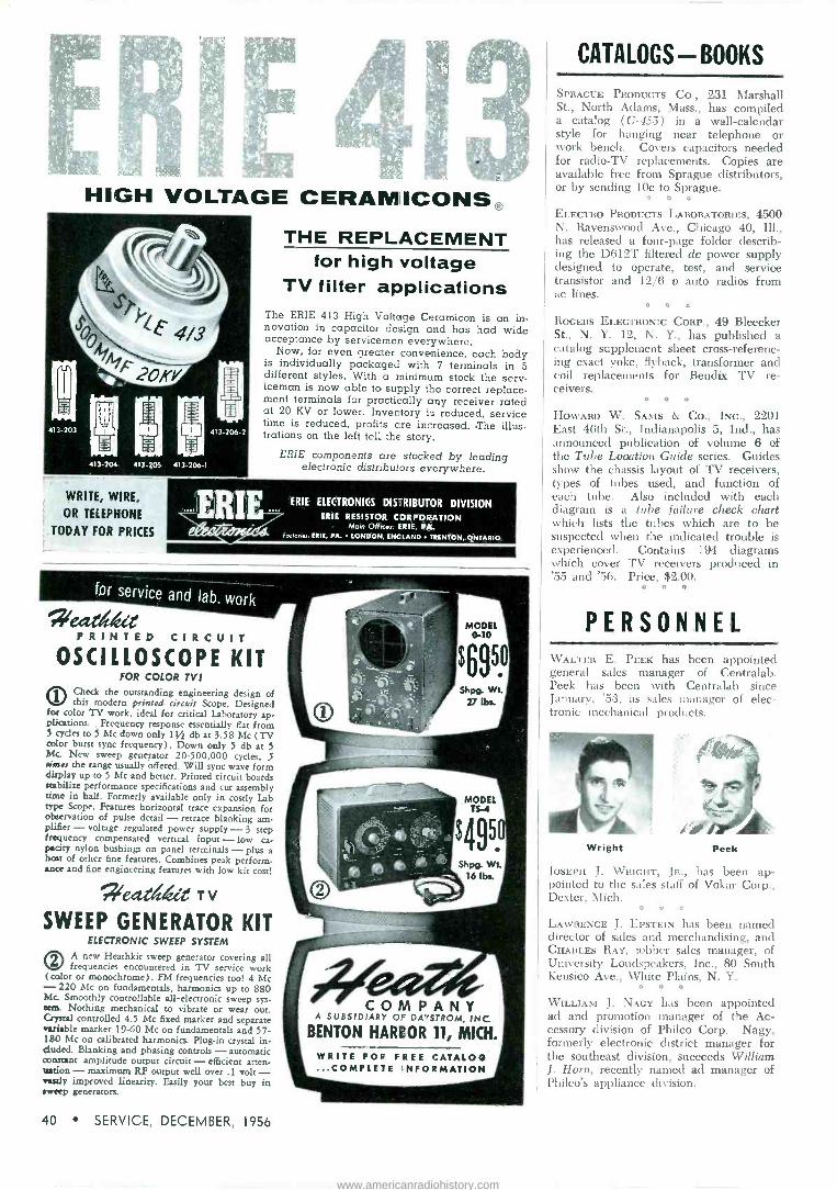
HIGH VOLTAGE CERAMICONS® THE REPLACEMENT
for high voltage TV filter applications
The ERIE 413 High Voltage Ceramicon is an in- novation in capacitor design and has had wide acceptance by servicemen everywhere.
Now, for even greater convenience, each body is individually packaged with 7 terminals in 5 different styles. With a minimum stock the serv- iceman is now able to supply the correct replace- ment terminals for practically any receiver rated at 20 KV or lower. Inventory is reduced, service time is reduced, profits are increased. .The illus- trations on the left tell the story.
ERIE components are stocked by leading electronic distributors everywhere.
WRITE, WIRE,
OR TELEPHONE
TODAY FOR PRICES
siearlskrs
ERIE..
PRINTED CIRCUIT
ERIE ELECTRONICS DISTRIBUTOR DIVISION ERIE RESISTOR CORPORATION
Main Offices: ERIE, PA.. Focrones: ERIE, PA. LONDON, ENCLAND . TRENTON, ONTARIO
OSCILLOSCOPE KIT FOR COLOR TV!
1tIN Check the outstanding engineering design of MY this modern printed circuit Scope. Designed for color TV work, ideal for critical Laboratory ap- plications: Frequency response essentially fiat from 5 cycles to S Mc down only 11/2 db at 3.58 Mc (TV color burst sync frequency). Down only 5 db at 5 Mc. New sweep generator 20.500,000 cycles, 5 rime the range usually offered. Will sync wave form display up to 5 Mc and better. Printed circuit boards stabilize performance specifications and cut assembly time in half. Formerly available only in costly Lab type Scope. Features horizontal trace expansion for observation of pulse detail - retrace blanking am- plifier - voltage regulated power supply -3 step frequency compensated vertical input - low ca- pacity nylon bushings on panel terminals - plus a host of other fine features. Combines peak perform- ance and fine engineering features with low kit cost!
e4ItedieleTV
SWEEP GENERATOR KIT ELECTRONIC SWEEP SYSTEM
OA new Heathkit sweep generator covering all frequencies encountered in TV service work
( color or monochrome). FM frequencies too! 4 Mc - 220 Mc on fundamentals, harmonics up to 880 Mc. Smoothly controllable all -electronic sweep sys- tem. Nothing mechanical to vibrate or wear out. Crystal controlled 4.5 Mc fixed marker and separate variable marker 19-60 Mc on fundamentals and 57- 180 Mc on calibrated harmonics. Plug-in crystal in- cluded. Blanking and phasing controls - automatic constant amplitude output circuit - efficient atten- uation - maximum RF output well over .1 volt - wastly improved linearity. Easily your best buy in sweep generators.
COMPANY A SUBSIDIARY Or DAMSTROM, INC
BENTON HARBOR 11, MICH.
WRITE FOR. FREE CATALOG ...COMPLETE 'INFORMATION
CATALOGS - BOOKS
SPRAGUE PRODUCTS Co., 231 Marshall St., North Adams, Mass., has compiled a catalog (C-455) in a wall -calendar style for hanging near telephone or work bench. Covers capacitors needed for radio -TV replacements. Copies are available free from Sprague distributors, or by sending 10c to Sprague.
n*
ELECTRO PRODUCTS LABORATORIES, 4500 N. Ravenswood Ave., Chicago 40, Ill., has released a four -page folder describ- ing the D612T filtered dc power supply designed to operate, test, and service transistor and 12/6 e auto radios from ac lines.
A * A
ROGERS ELECTRONIC CORP., 49 Bleecker St., N. Y. 12, N. Y., has published a catalog supplement sheet cross-referenc- ing exact yoke, flyback, transformer and coil replacements for Bendfx TV re- ceivers.
* A} C
HOWARD W. SAMS & Co., INC., 2201 East 46th St., Indianapolis 5, Ind., has announced publication of volume 6 of the Tube Location Guide series. Guides show the chassis layout of TV receivers, types of tubes used, and function of each tube. Also included with each diagram is a tube failure check chart which lists the tubes which are to be suspected when the indicated trouble is experienced. Contains 194 diagrams which cover TV receivers produced in '55 and '56. Price, $2.00.
* O o
PERSONNEL WALTER E. PEEK has been appointed general sales manager of Centralab. Peek has been with Centralab since January, '53, as sales manager of elec- tronic mechanical products.
Wright Peek
JOSEPH J. WRIGHT, JR., has been ap- pointed to the sales staff of Vokar Corp., Dexter, Mich.
V O C
LAWRENCE J. EPSTEIN has been named director of sales and merchandising, and CHARLES RAY, jobber sales manager, of University Loudspeakers, Inc., 80 South Kensico Ave., White Plains, N. Y.
C A C
WILLIAM J. NAGY has been appointed ad and promotion manager of the Ac- cessory division of Philco Corp. Nagy, formerly electronic district manager for the southeast division, succeeds William J. Horn, recently named ad manager of Philco's appliance division.
40 SERVICE, DECEMBER, 1956
www.americanradiohistory.com

Service Engineering (Continued from page 22)
stall and maintain this equipment. Therefore, Service Men should be- come familiar with how Conelrad works and how it can be used to safe- guard life and property.
An example of how the monitor may be integrated into a fairly complex radio station setup is illustrated on page 22. In this case, a plant music system is involved, as would be found in a factory employing an industrial or plant protection mobile radio sys- tem. The audio output of the receiver is available continuously at terminals 8 and 9 at the back of the monitor. Normally, the builtin loudspeaker in the instrument is disconnected with the monitor switch in silent position and the audio output is loaded by a 4.7 -ohm resistor. To feed this signal into an audio amplifier, a series re- sistor may be used to reduce the signal level to the proper value re- quired by the amplifier. The 470,- 000 -ohm series resistor, Rr, may be a potentiometer. Its value depends upon the input impedance of the am- plifier and may be adjusted by meas- uring the signal level at the input of the amplifier with a vtvm or a 'scope. The value of R1, another 470,000 -ohm series resistor, also de- pends upon the input characteristics of the amplifier and might be omit- ted when the amplifier input is al- ready loaded down internally by a resistor. By application of Ohm's law, the correct resistance values can be determined when the amplifier in- put impedance and signal level re- quirements are known.
The circuits shown connected to the other terminals are not affected until the monitor's alarm circuit is tripped. When this happens, the audio output of the receiever continues to reach the music system, but it now is also fed into the telephone line which links the base station transmitter, the re- mote control point and several dis- patch points. The audio level must now be reduced so that a 0 dbm signal is applied to the telephone line. This could be done with a T -pad made up of three fixed resistors, if the telephone line were not balanced to ground and the receiver audio output did not have one side grounded. Therefore, to offset this problem, a transformer, T,, is required. This may be a voice coil to a balanced line transformer. It is not critical. A 3000 -ohm potentiometer (Rs) in the rf gain circuit, which is also con- nected as a rheostat, can be adjusted
(Continued on page 43)
ENGINEERS: DO YOU WANT A MORE
CHALLENGING CAREER in the Analysis Modification Redesign
Maintenance Engineering of Advanced Navy Operational Airborne Electronic
Systems and Missiles?
IT IS YOURS WITH RCA
IF YOU HAVE
College degree or its equivalent in experience.
A minimum of 4 years' industrial and/or mili- tary electronic experience.
A desire for East or West Coast location with an
opportunity for travel to countries, such as
Hawaii, Japan, Alaska or in the Mediterranean Area.
A desire to receive a starting salary of $7000
and up yearly. Travel allowance, relocation re-
imbursement for you and family in U. S. Travel expenses and living allowance overseas.
ARRANGE FOR CONFIDENTIAL INTERVIEW
WITH REPRESENTATIVES OF
RCA ENGINEERING MANAGEMENT
AT A LOCATION CONVENIENT TO YOU
Please send complete resume to:
Mr. John R. Weld Employment Manager, Dept. Y -11M Radio Corporation of America Camden 2, New Jersey
RCA SERVICE CO., INC.
SERVICE, DECEMBER, i96 41
www.americanradiohistory.com

FLUTTER METER dependable & reliable
Eliminates all guesswork
Saves time and increases production
Makes satisfied customers
Model FL -3C ... for measuring, testing and servicing
Tape Recorders and Turntables
LOWEST PRICED INSTRUMENT... HIGHEST QUALITY
The rare case where the best costs less
Features: Specifications: Simple operation-tape Accuracy: 5% recorders-turntables Bandwidth: 0.5 to 250 cps Internal 3kc carrier Input: 250,000 ohms; 0.7 rms oscillator full limiting Light weight-easily portable Dimensions: 7""x 12"x 6" black Regulated power supply case with gold trim
Complete 5 -step instruction plate on top of case
dai t_. T o_
Manufacturers Electronic and Electro -Mechanical
Equipment & Components
Price $185.00 Order direct or write us for
name of nearest representative
404 East Gutierrez Street P.O. Box 1500 Santa Barbara, California
Telephone: WOodland 5-4511
Electrostatic Speakers (Continued from page 13)
mass of the diaphragm becomes im- portant, and the output starts to fall off somewhat.
A speaker mounted in a cabinet front is illustrated in Fig. 2 (p. 13) .
The arrows represent sound waves which move normal to the diaphragm surface, both front and back; the back plate is transparent acoustically.
If the cabinet front is not to cast an acoustic shadow, the center of the speaker must be close to the front of the cabinet. Minimum overall depth
results when the output from the back of the diaphragm is used. The polar distribution is the same from either side of the diaphragm.
When the sound is taken from the back of the diaphragm, the non - radiating sections (marked AA) are normally in the useful sound field. These sections are necessary me- chanically in order that the dia- phragm can be held under uniform tension. Their presence in the sound field causes undesirable absorptions at frequencies where they are resonant. To eliminate these absorptions they are removed from the radiating sound field by two pieces of impregnated
fibre and two pieces of tape which cover the last three diaphragm sections on either side.
Vertically the speaker has been found to be flat within 3 db over an angle of 15°; in the phono with this model, the speaker has been tilted upward at an angle of 15°, so that the full listening space can be covered at ear levels.
In this speaker the spacing between the diaphragm and the back plate must be carefully controlled. Spacing must be large enough so that the diaphragm will not strike at maximum excursion, yet not so far as to reduce the sensitivity unnecessarily. It was found that a favor- able compromise on spacing can be ob- tained by restricting the low frequency energy fed the diaphragm. This is part of the function of the crossover network which must be used with this speaker.
The crossover network used in our phono is shown in Fig. 4 (p. 13). In this network, section A compensates for the rise in the speaker output which centers at 6000 cps. A 4700 -ohm resis- tor is used to broaden the loss curve so that the compensated response is almost flat. Section B attenuates frequencies below 2000 cps. The inductance reso- nates with the capacity of the speaker to increase the output of the system in the 2000-2500 cps range. Here a 2500 - ohm resistor is used to broaden the reso- nance curve. Section C, consisting of a .22-mfd capacitor, blocks the do path through the choke and 2500 -ohm resis- tor.
Section D is the electrostatic speaker. Electrically, the reflected mechanical im- pedance is so small that it may be ne- glected. The speaker acts like a .016- mfd capacity. The polarizing supply and 4.7-megohm isolating resistor are in sec- tion E.
Servicing Helps (Continued from page 25)
excess solder brushed away; this should be repeated until the lugs are entirely free of solder.
Then the lugs should be cut from the transformer as close to the board as pos- sible, and the transformer removed.
Any small particles of solder imbedded in the resin should then be removed.
The replacement transformer should now be inserted and the connections soldered.
Finally a coat of lacquer should be applied to the connections.
P -W Tube Socket Replacement
Wafer type socket should be broken with pliers and all pieces removed so that the pins are exposed individually. One must be careful not to apply exces- sive pressure or twist the pin during this process or the foil wiring on the board will be damaged.
Now heat should be applied to the bot- tom of each pin, which should be removed individually by pulling straight up.
In the final step, all excess solder should be brushed away and a new socket installed.
42 SERVICE, DECEMBER, 1956
www.americanradiohistory.com

Service Engineering (Continued from page 41)
so that the signal level measured across
the high impedance side of T, is 0 db or approximately one volt.
Normally, program material flows from
the monitor to the public address system. When an alert is received, the bell rings,
the transmitter is disabled and the moni-
tor warning tone may be heard over
the public-address system, as well as
through the loudspeakers in the trans- mitter remote control and dispatch units.
The operator may disconnect all of
the control units from the transmitter by opening switch S2, but may continue to communicate with the dispatch points over wire lines. When he switches the monitor to 640 or 1240 kc he, as well
as personnel at dispatch points, plus all
of those within hearing range of the
public-address system, may listen to civil
defense information. Not all radio stations are located in
areas close to a key broadcasting station which must be monitored. Therefore, the monitor employs a sensitive receiver circuit enabling it to operate on very weak signals. When used in areas of high signal strength, receiver sensitivity may be reduced by adjustment of the rf gain
control, accessible from the rear of the chassis. One or all of the channels may
be crystal controlled by adding a suit- able crystal in the local oscillator circuit for each channel to be controlled. This may be desirable in areas of very weak signals.
The monitor has been designed to be used with various types of antennas as
dictated by local conditions. In areas of
low noise and high signal strength, a
ten foot piece of wire connected to the HI antenna terminal will usually suffice. In remote areas, a conventional horizon- tal T or inverted L antenna may be more satisfactory. In very noisy areas, a verti- cal whip antenna, at least 10' long, may be installed high above the vincinity of interference sources. A 50 or 75 -ohm coax cable may be used as the leadin. A
LO -impedance antenna terminal is pro- vided for this purpose.
When replacing components which are not identical to the original, it is im- portant to determine that the replace- ment parts are also designed for 24 -hour per day, year around operation. Care should be exercised not to damage the relay contacts or to disturb spring ten- sion when burnishing relay contacts or making adjustments to the relay. When any doubt exists, and since this instru- ment is concerned with safety, it may be wiser to replace the relay assembly.
A great opportunity awaits the enter- prising Service Man who goes out after Conelrad monitoring business now. There are thousands of radio station operators who have not yet voluntarily complied with the FCC requirement and who have made no definite plans for compli- ance. The sale and installation of Conel- rad warning systems can bring in rev- enue now and the maintenance of these systems will provide income in the future.
Leave a trail of happy customers...
replace with Sonotone Cartridges! Every time you replace with a Sono - tone 1P (single -needle) or 2T (turn- over) you're sure of another highly satisfied customer. Both Sonotone Ceramic Cartridges give sparkling, long-lasting and trouble -free per- formance-almost always better than original equipment.
New standard of the phono industry In more than half the quality phonographs made today by leading manufacturers, you'll find one of these Sonotone cartridges. All the more reason why you should standardize on Sonotone.
And every time you replace with a
Sonotone, you're better bff, too. Both models mount the same easy way- take care of over 90% of your quality replacement calls! With only 2 mod- els to work with, you can do the same job the same way, time after time, easier and faster.
Electronic Applications Division
SON OTO N E" CORPORATION ELMSFORD, N. Y.
IN CANADA, CONTACT ATLAS RADIO CORPORATION. LTD., 50 WINGOLD AVE., TORONTO
SERVICE, DECEMBER, 1956 43
www.americanradiohistory.com

"Now let's see if you can remember to bring home
those JENSEN NEEDLES tonight!"
?Lein SUBMINIATURE
POCKET TESTER
MODEL A-1000
only
$5.95 NET
The Model A-1000 Pocket Tester is sup- plied complete with instructions.
A true subminiature pocket tester which affords services equal not only to one but eight separate instruments, compactly mounted in sturdy metal case.
SPECIFICATIONS: LOW VOLTAGE TESTER 11000V1 A.C., D.C. HIGH VOLTAGE 150 K.V.) A.G.C. SUBSTITUTION VOLTAGE SUPPLY SIGNAL TRACER AUDIO OSCILLATOR CONDENSER TESTER CONTINUITY TESTER VISUAL OUTPUT METER 3" x 4" x 1 t/. rr
HSALES CO. of N.Y. 130 LAFAYETTE STREET NEW YORK CITY 13, N. Y.
Audio (Continued from page 33)
spindle adapter to increase opera- tional reliability.
The newer adapter has only one lug in the bottom opening, while the earlier model had two.
In some cases even the new type 45 adapter may not function properly, due to insufficient lateral motion of the record spindle pawl.
To remedy, the lock nut should first be loosened and stop screw turned in about 3 or 4 turns. Then, the record dropping slide should be pushed to the extreme of spindle pawl travel without forcing. While holding the slide in this position, the stop screw should be adjusted so that it just touches the spindle pawl. The lock nut can then be tightened.
Now, the roller adjust screw should be loosened and the changer run through cycle by hand, until the roller has given the record dropping lever maximum travel. The main gear should be held in this position and the roller adjust screw tightened.
To operate the changer by hand, the ac line should be removed and the operating knob turned to reject position. The main cam can now be rotated by hand in a counter -clock- wise direction looking at the bottom of the changer. One should not ro- tate the opening knob in the stop direction as the record -dropping lever will not engage the roller.
Changer should then be checked with the 45 spindle. Also, one should check operation with a single record
FIG. 1: CROSS-SECTIONAL view of
IMPROVED (bottom) and early (top) de- sign of 45 spindle adapter for Magnavox-
Collaro changer.
on the spindle after the changer has shut off automatically. If the changer drops the record, but the tone arm returns to its rest, it will be necessary to adjust the roller slightly in the di- rection opposing the spring tension.
Phono Output Step Up
SERVICE MEN ARE FREQUENTLY con- fronted with requests to improve the performance of old one or two -tube amplifier -turntable combinations. Sub- stantial improvement usually obtains
lever -type cartridge. (Courtesy Shure)
2' Nom \\\\ Record Surface t' t r J (L
16° Nom
3 Mil Needle in Playing Position
- I Md Needle
44 SERVICE, DECEMBER, 1956
www.americanradiohistory.com

FIG. 2: TYPICAL AMPLIFIER used in portable record player, whose output can be increased through use of high -
gain cartridges. IRCA RS -153)
when the normal complement of tube and component replacements are in- stalled, but a tremendous boost in quality and volume can result when a new high -gain cartridge is included in the replacement package.
For such replacement applications there has been developed a dual - needle twin -lever cartridge that, it is said, can provide a 5 -volt output and with extended range.* The needles (either a 3 -mil for 78 or a 1 -mil for 45 and 33-1/3) are installed in a shift mechanism which eliminates cartridge rotation for needle selection.
The 5 y output, obtained at 1000 cps for 78 records, has been found to provide enough drive to a 25L6 one - tube amplifier to produce 13 watts; a two -tube amplifier could develop better than two watts.
The high output voltage is ob- tained, the design engineers say, because of the use of a system of second -order levers. The crystal el- ement, which produces voltage when bending stress is applied, is held firmly between two elastomer pads at one end. The other end is attached to a coupler lever, held at one end in an elastic pivot. The other end of this lever is bifurcated, forming a saddle which receives the needle. The needle forms the second lever, having one end flattened in the verticle plane to provide a flexible pivot; whereas the other end has a stylus which is in contact with the record groove. It is possible to select the lever ratios to provide an impedance match between the record groove and the element as required. For example, if the element is mounted close to the pivot point of the coupler, the coup- ling lever provides a high lever ratio resulting in a high lateral compliance and a relatively low output voltage. ---
*Shure W9
You'll find that Quam speakers are heavier than
other speakers of equivalent size and
magnet weight-because they are built of stronger,
finer quality materials.
Quam speakers have heavier gauge metal
baskets ... larger and more efficient magnetic
structures ... more insulating and
impregnating materials. The result is a more
rugged, longer lasting speaker that is sure to be in perfect operating
condition when you take it out of its factory
package. Quam speakers are always shipped in
individual protective cartons ... never in bulk!
COMPARE
THE WEIGHT
of a
QUAM Aeusta,
SPEAKER
QUAM-NICHOLS COMPANY
232 EAST MARQUETTE ROAD CHICAGO 37, ILLINOIS
ask ßa1 QuaM,tie. quality ikleC di yours. yak/tads
This condition might be chosen if fidelity is the primary requirement. In low -gain amplifiers, a compromise must be made to obtain higher output voltage. This is accomplished by locating the crystal element further from the pivot point.
The use of separate needles has important advantages. Since 78 records have a greater groove mod- ulation than the fine groove records, it is necessary to re -adjust the volume control of the record player when switching from 78 to fine groove
records or vice-versa. By adjusting the voltage sensitivity of the pickup so that it is less with a 1 -mil needle, nearly equal output is possible from the standard 1p records. Conversely, 78 discs require a greater compliance for a given needle load than do the fine groove records, and this is also compensated by the use of two needles.
The cartridge mounting ears have been so designed that they will fit arms having standard '=" mounting centers.
SERVICE, DECEMBER, 1956 45
www.americanradiohistory.com

Packaged Electronic Circuits (Continued from page 19)
other components in the stage, before checking the pec. If a visual check of the pec shows that it is not cracked or burned, and the solder joints are good, you will usually find that the trouble lies elsewhere.
In the event that tests of the sur- rounding components do not disclose the trouble, then the packaged com- ponents should be checked in the fol- lowing manner.
If the simple resistance -capacitance network is suspected one should first disconnect the leads and make re- sistance and capacitance checks at the terminals available. If these tests in- dicate normal resistance and capaci- tance values then troubleshooting should be expanded to the remainder of the chassis.
To check the triode and pentode couplates, a signal and waveform check should be run from the input of the preceding tube (detector-avc- af) to the output of the pec, and an- other check from the input of the pec to the output of the following tube; audio output. If in both checks, the waveform -signal information is in or- der, the pec must be good; if in either test a defect is revealed, the pec should be replaced.
The audio detector and pentode detector units should be checked by the same procedure as detailed for the triode and pentode couplates.
The vertical integrator test involves several checks in the circuit. The in- put to this network is the composite sync signal, consisting of both hori- zontal and vertical sync pulses. The purpose of the circuit is to collect and integrate the vertical pulse, which in the composite signal is a series of narrow pulses, interrupted by nar- rower horizontal sync pulses of op- posite polarity. The output of the vertical integrator is a broad sync pulse of correct polarity, and roughly triangular in shape. This pulse can best be checked by removing the ver- tical oscillator tube, since the large pulse fed by the vertical oscillator may mask the vertical sync pulse so that it can hardly be seen. With the oscillator operating, a large negative spike is normally present, just follow- ing the vertical sync signal.
To check the sync takeoff units a strong local station should be tuned in, and then the input and output waveforms should be observed. The input waveform should display both vertical and horizontal sync pulses, and also video signal modulation. The sync takeoff unit acts as a broad band-
still TOPS...
the
' Impedance match
Signal transfer
gf2-Set isolation
With the MOSLEY Dual -Match TV Coupler "convenience" becomes a byword for the folks who have that extra TV for the den or play -room!
The Dual -Match Coupler is efficient, solderless, compact and so easily in- stalled on baseboard or set-yet priced so low you are assured complete cus- tomer satisfaction.
Available at Radio and Television Parts Distributors, Coast -to -Coast.
MOSLEY 902 List Price
MDsr/Pq egc,./Z074,, c9/14
1027 ST. CHARLES POCK ROAD ST LOUIS 14. MISSOURI
pass filter, passing both the vertical and horizontal sync pulses, and at- tenuating random pulses outside this frequency range which might other- wise trigger the sync units. The effect of this attenuation is not detect- able on the average 'scope, however, and therefore the output waveform should be approximately the same as the input waveform in appearance and amplitude. If both input and output waveforms are okeh, the pec is good. If either waveform is not correct, the pec may be at fault and should be replaced.
In many instances special circuit units can be checked by signal and
46 SERVICE, DECEMBER, 1956
www.americanradiohistory.com

ADVERTISERS IN SERVICE
DECEMBER, 1956
Page Acme Electric Corp 38
Allied Radio Corp. 47
American Pamcor, Inc 24
Argos Products Co.... 2
Bussmann Manufacturing Co.
Centralab, A Div. of Globe -Union, Inc.
6
1
Channel Master Corp. 12
Chemical Electronic Engineering, Inc... 34
Cornell-Dubilier Electric Corp,. Inside Front Cover, 37
D & R. Ltd. 42
Eby Sales Co. of New York 44
Erie Resistor Corp. 40
Fast Chemical Products Corp.. ..... .. 35
Federal Telephone and Radio Co., Com- ponents Div. 5
General Cement Manufacturing Co., Div. of Textron, Inc. 29
Heath Co 40
Jackson Electrical Instrument Co. 48
Jensen Industries, Inc. 44
Kaar Engineering Corp 35
Kenwood Engineering Co., Inc. 47
Kester Solder Co. 36
Lenk Manufacturing Co. 48
P. R. Mallory & Co., Inc. Inside Back Cover
Merit Coil and Transformer Corp. 34
Mosley Electronics, Inc. 46
Perma-Power Co 34
Pyramid Electric Co. 4
Quam-Nichols Co 45
The Radiait Corp.. Inside Front Cover, 37
Radio Corporation of America, Tube Div. Back Cover, 3, 7
Raytheon Manufacturing Co... ....... 8
RCA Service Co., Inc. 41
Remington Rand Univac, Div. of Sperry -Rand Corp. 23
Snyder Manufacturing Co. 32, 35
Sonotone Corp. 43
South River Metal Products Co., Inc.... 35
Trio Manufacturing Co. 46
Tung -Sol Electric, Inc. 17
United Catalog Publishers, Inc 39
Utica Drop Forge and Tool Div. of Kelsey -Hayes Wheel Co 25
Weston Electrical Instrument Corp., A Subsidiary of Daystrom. Inc.
Winegard Co
36
38
waveform measurements. The exact nature of the waveforms to be ex- pected will vary depending on the application, and service literature sources should be consulted for de- tailed information. Where this in- formation is not available, a simple check can be made by disconnecting the pec leads and checking resistance and capacitance between available terminals.
Selecting the Replacement Unit
When a defective pec is found, the correct replacement unit can be lo- cated from service literature. But, a word of caution is in order here. One must not attempt to replace a pec with individual components, because the basic construction of these pack- aged elements incorporate factors (such as distributed capacity) which in many cases cannot be duplicated by individual components. On the other hand, it is usually possible to replace individual components with pec's.This is particularly true in the case of vertical integrators, sync take- off units, and couplates.
Installation Techniques
Practically all pec replacement units available today are wire -lead type. These will replace either wire -lead or tab type units. When installing a pec replace- ment one must be certain that the right leads are in the right locations. Some pec replacements have the lead location in a different sequence than the pec unit which was removed. Therefore, one should trace the circuit diagram care- fully when installing a new unit. It is also desirable to install the replacement unit in the same location, and with the same lead dress, as for the removed unit.
Today many chassis use etched wiring or plated wiring boards.' Special care must be taken with these chassis be- cause of the fragile nature of the wiring. When removing the old unit, it is best to clip the leads or tabs close to the body of the pec and remove the cut-off leads one at a time. A pencil type sol- dering iron, approximately 25 -watt size, should be used here. One should not use a high -voltage soldering gun or iron. Heat in excess of that required to melt the solder may damage the board, or the bond between the wiring and the board.
The increased usage of pec's makes it desirable for the TV repair shop to carry a basic replacement assortment in stock.
An average inventory could consist of a standard couplate, pentode couplate and two audio detector couplates; two midget couplates and seven vertical in- tegrators. This stock represents the most popular triode and pentode couplates, audio detector couplates, and vertical integrators.
'See Servicing Helps, this issue, p. 25.
KENCO KATE SAYS
"NO INSTALLATION
PROBLEMS when you use KENCO
l MOUNTS"
Patented Fenno Fave Mounts
Easily mount.. hanging rafters or trim boards of eave. Eliminates need for drilling in- to brick or masonry walls. Ideal for buildings with ex- tended roofs. Hot dip galva- nized.
Available in 3 sizes: Model # 122...22" Eave Mount Model # 128 ..28" Eave Mount Model # 148...48" Eave Mount OTHER KENCO RODUCTS: All -Position Mounts: Parapet Mounts: Sky Struts: "Snap - In" Wall Brackets; "Snap -In" Chimney Mounts: Z -Type
Chimney Mounts: Lag Screws and Hardware.
KENWOOD ENGINEERING Co., INC.
Kenilworth, New Jersey
Build -Your -Own knight -kit
TRANSISTOR 8, DIODE
CHECKER KIT
Save on this valuable new instrument! Checks leakage -to -gain ratio and
0 noise level of all junc- tion, point contact and barrier transistors. Can
also check germanium and silicone diodes. and forward and reverse conduction of selen- ium rectifiers. Useful for continuity and short tests, as well as for noise level tests. Features spring -return leakage gain switch, calibration control, full -vision meter, separate sockets for PNP and NPN type transistors. Complete kit with bakelite case, all parts, 22v. battery and instructions. Shpg. wt., 23 lbs. Model 83 Y 149. Net only $8.50
Net F.O.B. Chicago
356 -PAGE ALLIED CATALOG Lists dozens of other low- cost quality Knight -Kit test instruments, plus the world's largest selection of parts and equipment for service work. Write for FREE copy.
t ALLIED RADIO, Dept. 23-M-6 mis 100 N. Western Ave., Chicago 80, III. 7774
D Send Kit described above. enclosed
D Send FREE 356 -Page ALLIED Catalog ten
IN Name - a Bs Address V
1,1A1111111111l11.a1111111l11111111I111111111/
SERVICE, DECEMBER, 1956 47
www.americanradiohistory.com

TVG -2 Sweep Marker Generator
Dealer Net $259.95
A complete TV generator plus crystal calibrator. Sweep 30KC through 216MC. Width adjustable from 0 through 18MC. Accurate Marker 4MC through 216MC. Crystal oscillator for frequencies to 20MC. Provision for Video Modulation.
CRO-2 Wide Band
High Sensitivity 5 -inch Scope
Dealer Net $225.00
7 Flat within 1 db from 20 cycles through 4.5MC. Sensitivity from .018RMS volts per inch. Positive or Negative internal horizontal sync. Saw tooth sweep 20 cycles through 50KC. Many accessories including low capacity probes.
Model 655 Wide Range
Audio Oscillator Dealer Net $135.00
Highly stable RC sine wave genera- tor, Range 20 cycles to 200 kc in 4 steps. Up to 500 milliwatt output at impedances of 10, 250, 500, 5000 ohms or HiZ. Frequency char- acteristic 1db., 30 to 15k cycles. Accuracy 3% or 1 cycle.
_....-.l; t
Model 648A Dynamic R
Tube Tester Dealer Net $129.95
Fastest tester on the market-and fea- turing famous Jackson Dynamic Circuit. Meter calibrated in Good -Bad, as well as percent Transconductance. Correct test voltage for all tubes including latest 600 -mil types. Une Voltage Indicator.
J ACJ(S Q INSTRUMENT CO.
World's largest exclusive makers of factory -built service test equipment.
16-18 S. Patterson Boulevard Dayton 2, Ohio In Canada: The Canadian Marconi Co.
Tube News A LINE of eight auto -radio miniatures designed to operate at 12 -volts is now available.'
Included is a 12J8, a 9 -pin minia- ture detector -driver, said to produce high current at low plate voltage for optimum power coupling to an out- put transistor. Other types include 7 -pin miniature pentode rf amplifiers, 124106 and 12AF6; a 7 -pin miniature pentagrid converter, 12AD6; a multi- unit 9 -pin miniature containing two diodes and a remote cutoff pentode, type 12F8; a 7 -pin miniature space charge tetrode driver, 12K5; 9 -pin miniature audio amplifier, 12AE6, and medium mu 9 -pin miniature double triode, 12U7.
Type 12j8 has a 12.6-v, 350 -ma heater; type 12K5 has a 12.6-v, 400 - ma heater. The remaining six types have 12.6-v, 150 -ma heaters.
TV Tubes For vertical - deflection amplifier
service in TV receivers utilizing pic- ture tubes having diagonal deflec- tion angles of 110°, a 6CZ5 beam - power tubez has been developed.
The tube, a high perveance type, utilizes a T-6% miniature envelope and has a 6.3 v/.45 ampere heater. It has a maximum peak positive -pulse plate voltage of 2,200 (absolute), a maximum peak cathode current of 140 ma, and a maximum plate dissi- pation of 10 watts.
Because of its sensitivity, the tube is said to be useful also in the audio output stages of TV and radio re- ceivers. When used in push-pull class AB1 service, the tube under fixed bias conditions can deliver a maximum signal power output of 21.5 watts with, it is claimed, a total harmonic distortion of 1 per cent.
Fifteen replacement tubes' for 450 -ma series -heater string TV chassis also have been announced.
Types include: 4AU6, 4CB6, and 4DT6 (sharp - cutoff pentodes) ;
5BQ7A (medium -mu twin triode); 6AM8A (diode-sharp - cutoff pen- tode) ; 6AQ5A (beam power tube) ;
6AT8A, 6CG8A, 6U8A (triode -pen- tode converters); 8AW8A (high -mu triode-sharp-cutoff pentode); 8CG7 (medium -mu twin triode) ; 8CM7 (medium -mu dual triode) ; 17AX4GT (half -wave rectifier); 17BQ6GTB and 17DQ6A (beam power tubes) .
AC/DC Tube Development A beam -power pentode miniature',
type 25C5, for use as a power am- plifier in the output stage of ac/dc receivers has been designed and is now available for the renewal market.
1Sylvania ARCA
You need a special tool for a special job .. .
Fue` "PRINTED CIRCUIT"
SOLDERING GUN for
Printed Circuits and Miniaturized
Components
Fast Soldering Exclusive "Controlled Heat" produces prop- er amount of heat for quick, easy soldering.
Prevents Damage Exclusive "Controlled Heat" reduces possi- bility of damage to delicate printed cir- cuits or miniaturized components.
Pin -Points the Work Precision -designed tip pin -points the tip on- to the work quickly and accurately.
Lightweight - Comfortable Exclusive "Easy Grip" handle and lightweight (only 1 lb. approx.) reduce fatigue.
Printed Circuit photograph courtesy of Electrolab, Inc.
Write for name of nearest Jobber
The LENK MANUFACTURING CO. 30 Cummington Street Boston 15, Mass.
48 SERVICE, DECEMBER, 1956
www.americanradiohistory.com

... another
MALLORY service -engineered
product
FP CAPACITORS
take high ripple currents
(all FP's are Mallory)
No need to worry about ripple currents, when you choose Mallory FP (fabri- cated plate) capacitors for replace- ment. They're built to handle the
toughest ripple ... even the values you find in the Latest color TV sets.
FP's, in fact, will stand 50 to 100% higher ripple current than usual indus- try expectaticn for a given rating. And this superior performance ... proved by tests at 85' C ambient ... can be
expected of all FP capacitors, for they are manufactured to highest standards of uniformity. Mallory's unique FP construction makes this possible. It
puts more electrolyte and more anode area into a smaller case ... to give better heat dissipating qualities.
Be sure to specify Mallory FP's by name, not only for high ripple applica- tions, but for all your electrolytic capacitDr replacements. See your local Mallory distributor today!
P. R. MALLORY 8 CO.Inc.
MALLORY' P. R. MALLORY A CO. Inc., INDIANAPOLIS 6, INDIANA
Capacitors Vibrators Resistors Controls Switches
Rectifiers Power Supplies Filters Mercury Batteries
www.americanradiohistory.com

Important features of RCA RECEIVING TUBES for dependable replacement in radio, phono, and TV sets!
"Low Background Noise... Long Life... Electrical Uniformity" are technical terms your service customers may not appreciate when talking to you about set troubles. But they do know when you have restored their sets to "like new" performance.
When the trouble is tube failure, you certainly want to minimize "tube juggling" and circuit realigning... to complete the service job quickly, confidently, profitably-with full customer satisfaction.
RCA enables you to give full customer satisfaction by controlling the quality of your replacement tubes. RCA's "don't spare the quality" selection of raw materials, stringent control of all manufacturing processes and techniques, second -to-none final inspection and testing methods are your assurance of tubes with low background noise, long life, electrical uniformity-your assurance that RCA RECEIVING TUBES are your most dependable replacement tubes!
1 RECEIVING TUBES RADIO CORPORAT±ON OF AMERICA
TUBE DIVISION HARRISON, N. J.
ALWAYS USE DEPENDABLE -(QUALITY TUBES... RCA 'ILAZES
www.americanradiohistory.com