the theoretical investigation and design on 0.42 thz gyrotron … · 2018-02-05 · the theoretical...
TRANSCRIPT
Terahertz Science and Technology, ISSN 1941-7411 Vol.9, No.4, December 2016
149
Invited Paper
The theoretical investigation and design on 0.42 THz gyrotron with
complex cavity
Sheng Yu * , Qixiang Zhao, Tianzhong Zhang, Youwei Yang, Yanyan Zhang, and Zhipeng Wang
Terahertz Science and Technology Research Center, University of Electronic Science and Technology of China,
Chengdu, 610054, China
* Email: [email protected]
(Received 21 December 2016)
Abstract: The research on terahertz science and technology are being intensified due to enormous potential in the field
of high-density plasma diagnostics and nuclear magnetic resonance (NMR). However, the lack of terahertz source
especially high power terahertz source is a main obstacle. Gyrotron, based on the ECRMs (Electron Cyclotron
Resonance Masers), is one of the most promising sources to generate high power terahertz radiation. Therefore, a
0.42 THz gyrotron operating at second harmonic is designed and analyzed in this paper. To alleviate the mode
competition, a gradually tapered complex cavity is adopted, where the pair of operating modes is TE17.3/TE17.4. a
candidate operating point is selected by linear and nonlinear theoretical analysis, with 50 kV beam voltage, 6 A beam
current and 8.03 T magnetic field, the output power and interaction efficiency can reach about 78.48 kW and 26.16%,
respectively. The mode competition in the designed gyrotron is also investigated with the time-dependent multi-mode
nonlinear code. The results show that the operating mode can be prior excited and other competing modes are
effectively suppressed. A double anode magnetron injection gun (MIG) with 3.19% maximum transverse velocity
spread is also designed and simulated to satisfy the requirement of the proposed gyrotron. These simulation results can
provide the theoretical basis for the 0.42 THz gyrotron experiments.
Key Word: Terahertz, Gyrotron, Complex cavity.
doi: 10.11906/TST.149-165.2016.12.15
I. Introduction
The gyrotron has been demonstrated to be an efficient, high power source of terahertz radiation,

Terahertz Science and Technology, ISSN 1941-7411 Vol.9, No.4, December 2016
150
based on the mechanism of electron cyclotron maser (ECM) [1-10]. Recently, the developments of
sub-terahertz and terahertz gyrotrons have been intensified because numerous applications of high-
frequency gyrotron are anticipated [11-22]. Motivated by the spreading applications, worldwide
research efforts have been spent on THz gyrotron. The gyrotron operating at 1.3 THz with an output
power of 0.5 kW has been investigated at the Institute of Applied Physics (IAP), Russia [23]. It is
the highest frequency radiation generated by gyrotron. A 0.67 THz gyrotron with record power and
efficiency has been developed in the joint experiments of IAP and University of Maryland [24].
The developments on 0.4 THz gyrotron for high power terahertz source are very meaningful due to
the application in Thomson Scattering (CTS) [25-26]. However, according to the ECM, the
required external magnetic field is over 15 T when a gyrotron operates at 0.4 THz with fundamental
harmonic oscillation. Therefore, to overcome the limitation caused by the achievable strength of
magnetic field, the high frequency gyrotron always operates at second harmonic of the cyclotron
frequency to decrease the applied magnetic field to half of that required by the fundamental
oscillation. Meanwhile, to achieve high power at higher frequency, the gyrotron has to operate
necessarily at high order mode to alleviate the problem of wall heating and beam interception due
to miniaturization of interaction structure at these frequencies. However, the undesired excitations
of lower harmonic modes present a major problem for stable operation of higher harmonic mode.
Therefore the complex cavity is selected as an interaction cavity to suppress the mode competition
for obtaining high power terahertz radiation. The complex cavity was proposed and first
experimentally studied in [27-35], which has been proved that it is capable of suppressing the
parasitic mode competition due to the mode conversion in the transition region [36-39].
As shown in Fig. 1, TE17.4 is an ideal candidate mode for second harmonic gyrotron because it
is well isolated from the neighboring modes, especially from fundamental modes. The profile of
complex cavity is shown in Fig. 2. It is obvious that the complex cavity is made up of two cavities .
The first cavity can pro-modulate the electrons, and the second one is the main energy exchange
place between modes and electron beam. Thus a pair of operating modes like TEmp/TEmn (p<n,
TEmp and TEmn are the modes in the first and second cavity, respectively. These two modes have
very close operating frequency) is formed in the complex cavity. In this paper, a 0.42 THz second
harmonic gyrotron with complex cavity operating at TE17.3/TE17.4 is designed and simulated by the
self-consistent nonlinear theory. Based on simulations, an optimal operating point is selected
carefully, which can generate about 78.48 kW terahertz radiation with frequency at 420.3347 GHz.
A corresponding double anode magnetron injection gun (MIG) is also simulated, whose maximum
transverse velocity spread is about 3.19 %, which satisfies the requirement from the designed
gyrotron. At the same time, the mode competition in the designed gyrotron is investigated by the
time-dependent, multi-mode nonlinear code. The simulation results show that the operating mode

Terahertz Science and Technology, ISSN 1941-7411 Vol.9, No.4, December 2016
151
TE17.4 can be first excited and other competing modes are well suppressed in the complex cavity.
And the capability of complex cavity to suppress the mode competition has been proved on the
basis of mode competition calculations. These simulation results can provide a theoretical basis for
the 0.42 THz gyrotron experiments.
This paper is organized as follows. In Section II, we have presented cold cavity simulation results.
Sec. III gives the linear analysis results. The hot cavity simulations are shown in Sec. IV. A
corresponding double anodes electron gun is designed in Sec. V. And the mode competition
calculations are presented in Sec. VI. Finally, the design scheme for 0.42 THz gyrotron is concluded
in Sec. VII.
32.0 32.2 32.4 32.6 32.8
16.0 16.1 16.2 16.3 16.4
The Fundamental Harmonic Modes
TE24.2TE
2.10TE
0.10
The Second Harmonic Modes
TE2.5
2
TE17.4
TE9.7
TE14.5
Fig. 1 Mode spectra of the TE modes.
II. Mode selection and cold-cavity simulations
In the design task of high power second harmonic gyrotron, it is very important to reduce the
risk of mode competition with neighboring modes, especially with the fundamental modes. The
distributions of the Bessel prime zero’s are plotted in the Fig.1. It is found that the TE17.4 is an ideal
candidate mode because it is well isolated from the neighboring modes TE9.7 and TE14.5, especially
from the fundamental mode TE2.5.
The cold-cavity field distribution and geometry of complex cavity are plotted in the Fig. 2. Based
on the transmission line theory, a pair of modes having the same azimuthal index is formed in the
complex cavity: TE17.3 mainly exists in the first cavity, and TE17.4 is only the mode in the second
cavity. The transverse electric field of TE17.4 is also plotted in Fig. 2. It shows that the transverse
electric field locates mainly at outer region of the cavity, which can increase the beam-wave
interaction space and decrease the magnetic compression ratio for high quality electron beam. For
adjusting the mode quality factor in the cavity, there is a throat added between the second cavity

Terahertz Science and Technology, ISSN 1941-7411 Vol.9, No.4, December 2016
152
and output cavity. The cold cavity are also simulated by the software HFSS, which have been
presented in Fig.3. It is well shown that the pair of the operating modes can exist stably in the
complex cavity and the simulation results are well close to the numerical simulation one.
0 1 2 3 4 5 6 7 8 9 10 11
0.0
0.5
1.0
1.5
2.0
2.5
3.0
3.5
4.0
4.5 Profile of Complex Cavity
Normalized Mode Amplitude of TE17.3 (Cold)
Normalized Mode Amplitude of TE17.4 (Cold)
Normalized Axial Distance (mm)
No
rma
lized C
av
ity R
ad
ius(m
m)
0.0
0.2
0.4
0.6
0.8
1.0
1.2
No
rma
lized M
od
e Am
plitu
de
Fig. 2 Geometry of the complex cavity and normalized cold cavity field profiles for TE17.3 -TE17. 4.
Based on the cold cavity simulation, the resonant frequency and diffractive quality factor are
listed in the Table.1. It is found that the fundamental mode TE2.5 has much lower quality factor
than that of TE17.4. However, the frequency and diffractive quality factor of TE9.7, TE14.5, and TE17.4
are very close. But they could be suppressed by selecting proper guiding radius of electron beam
based on the linear theory, which will be illustrated in the coming content.
Fig. 3 The cold cavity simulation with HFSS.
TAB. I THE RESONANT FREQUENCY AND Q OF DIFFERENT MODES
Mode The Resonant Frequency(GHz) Diffractive Quality Factor
TE17.4 420.3375 13140
TE9.7 422.7906 13592
TE14.5 419.3196 12938
TE0.10 418.7073 12797
TE2.10 TE24.2
TE2.5
417.9005 417.6726
213.9087
12647 12839
560
Terahertz Science and Technology, ISSN 1941-7411 Vol.9, No.4, December 2016
153
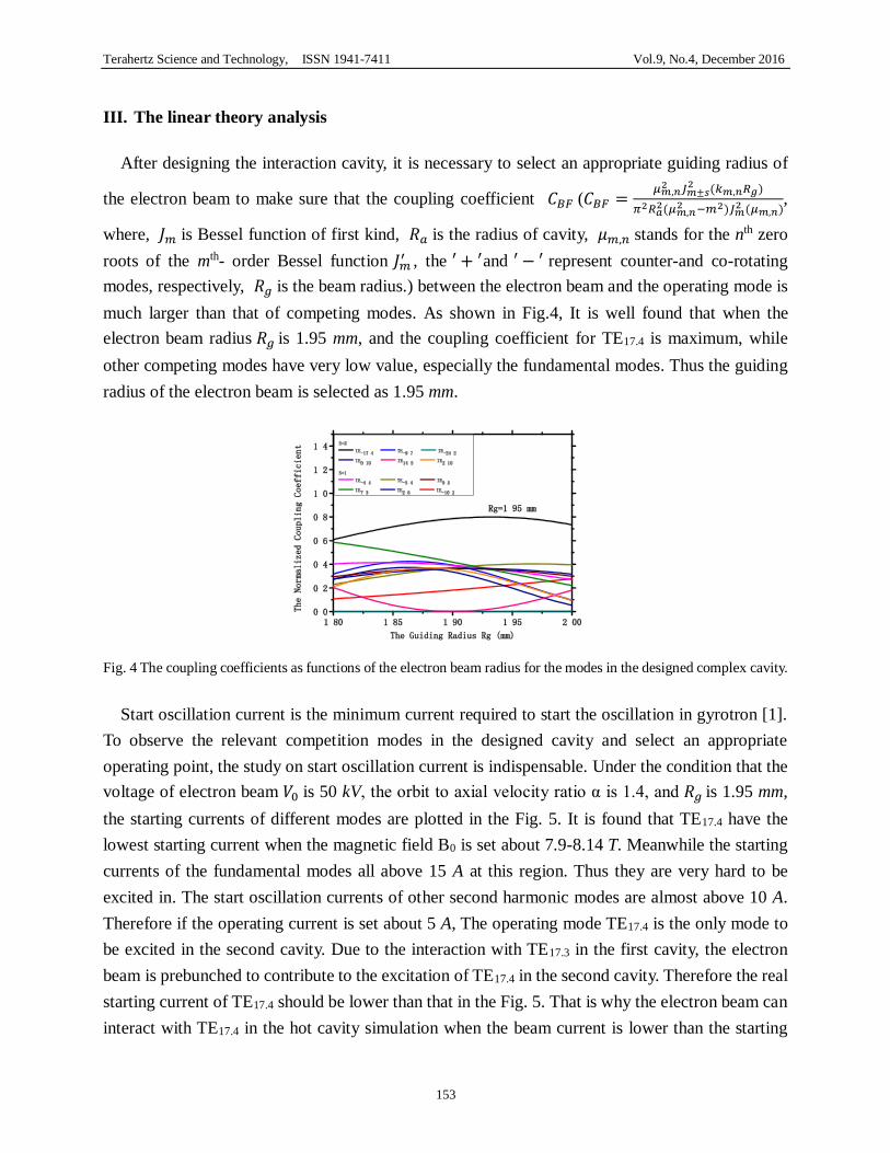
III. The linear theory analysis
After designing the interaction cavity, it is necessary to select an appropriate guiding radius of
the electron beam to make sure that the coupling coefficient 𝐶𝐵𝐹 (𝐶𝐵𝐹 =𝜇𝑚,𝑛
2 𝐽𝑚±𝑠2 (𝑘𝑚,𝑛𝑅𝑔)
𝜋2𝑅𝑎2(𝜇𝑚,𝑛
2 −𝑚2)𝐽𝑚2 (𝜇𝑚,𝑛)
,
where, 𝐽𝑚 is Bessel function of first kind, 𝑅𝑎 is the radius of cavity, 𝜇𝑚,𝑛 stands for the nth zero
roots of the mth- order Bessel function 𝐽𝑚′ , the ′ + ′and ′ − ′ represent counter-and co-rotating
modes, respectively, 𝑅𝑔 is the beam radius.) between the electron beam and the operating mode is
much larger than that of competing modes. As shown in Fig.4, It is well found that when the
electron beam radius 𝑅𝑔 is 1.95 mm, and the coupling coefficient for TE17.4 is maximum, while
other competing modes have very low value, especially the fundamental modes. Thus the guiding
radius of the electron beam is selected as 1.95 mm.
Fig. 4 The coupling coefficients as functions of the electron beam radius for the modes in the designed complex cavity.
Start oscillation current is the minimum current required to start the oscillation in gyrotron [1].
To observe the relevant competition modes in the designed cavity and select an appropriate
operating point, the study on start oscillation current is indispensable. Under the condition that the
voltage of electron beam 𝑉0 is 50 kV, the orbit to axial velocity ratio α is 1.4, and 𝑅𝑔 is 1.95 mm,
the starting currents of different modes are plotted in the Fig. 5. It is found that TE17.4 have the
lowest starting current when the magnetic field B0 is set about 7.9-8.14 T. Meanwhile the starting
currents of the fundamental modes all above 15 A at this region. Thus they are very hard to be
excited in. The start oscillation currents of other second harmonic modes are almost above 10 A.
Therefore if the operating current is set about 5 A, The operating mode TE17.4 is the only mode to
be excited in the second cavity. Due to the interaction with TE17.3 in the first cavity, the electron
beam is prebunched to contribute to the excitation of TE17.4 in the second cavity. Therefore the real
starting current of TE17.4 should be lower than that in the Fig. 5. That is why the electron beam can
interact with TE17.4 in the hot cavity simulation when the beam current is lower than the starting

Terahertz Science and Technology, ISSN 1941-7411 Vol.9, No.4, December 2016
154
current. This phenomenon is also observed in the experiment for the complex cavity gyrotron.
Fig. 5 The start oscillation currents Istart as functions of the magnetic field B0
IV. The self-consistent nonlinear simulation
The electric and magnetic field in the complex cavity could be written in the form
T zE zE E e (1)
T zE zH H e (2)
The transverse field 𝐸𝑇 and 𝐻𝑇 can be expanded in terms of orthogonal normalized wave
vector functions for the waveguide
2( ) ( )
1
( ) ( , )i i
T mn mn
i mn
V z r
E e (3)
2( ) ( )
1
( ) ( , )i i
T mn mn
i mn
I z r
H h (4)
Based on Maxwell’ equations, by utilizing the orthogonal and normality of the wave vector
functions, the general second-order transmission line equation with a current source is obtained for
the azimuthally symmetric system [36-40],

Terahertz Science and Technology, ISSN 1941-7411 Vol.9, No.4, December 2016
155
2 ( ) ( ) ( ) ( )2
( ) ( ') ( )( ')
' ( )( ')2' '
( ')( ) ( ')( ')( )( ) ( ) ( '') ( ')( ''
'' ( ')( '')( ') ( ')' ' ' '
(ln )( )
.{
i i i ii i i i imn mn mn mn
mn mn mn mn mn
i mn
i i imn mni i i i imn
mn mn mn mn mni ii mn mn mn
d V d Z dV dRV V C
dz dz dz Rdz
C dVdR dRZ V C
Rdz Z dz Rdz
')
'' ''
( ') 2( )( ') ( ') ( )( ')'( )( ') ' ( )( ')2
' ' ' '
22
}
[ ( )]
i mn
ii i i i imnmn mn mn mn mn
i mn i mn
imnmn mn t
s
dVdR d R dRC V C
Rdz dz Rdz Rdz
Z J e ds
(5)
where 𝑅 is the wall radius of cavity as a function of axial position, 𝑍𝑚𝑛(𝑖)
is the wave
impedance: 𝑍𝑚𝑛(1)
= 𝛾𝑚𝑛(1)
𝑗𝜔𝜀⁄ , 𝑍𝑚𝑛(2)
= 𝑗𝜇𝜔 𝛾𝑚𝑛(2)⁄ , (𝛾𝑚𝑛
(𝑖))2 = (𝑘𝑚𝑛
(𝑖))2 − 𝑘0
2 , 𝑘02 = 𝜔2𝜀𝜇 , and
𝐶(𝑚𝑛)(𝑚𝑛′)
(𝑖)(𝑖′)is the mode coupling coefficient, which is defined in [38, 39].
𝑱𝑡 is the transverse density of electron beam current, which is determined by
2
0
1( , ) ( )
2
j t
t t t e d t
J J r (6)
Particles have also been drove by the static magnetic field 𝐵0 and RF field. Then the motion of
a charged particle satisfies relativistic Lorentz’s equation, where 𝑚0 is the rest mass of particle.
00
( )( ( ))
d mq
dt
+
uE + u B B (7)
At the input end of the cavity, each mode included in the calculation must satisfy the condition
of an evanesce wave. And at the output end of the cavity, all propagating waves must satisfy
outgoing wave boundary condition. They are written as follows:
( )( ) ( )
0 0i
i imnmn mn z
dVV
dz (8)
( )2( ) ( )
1
0ii
i imnmn mn
i mn
dVV
dz
(9)

Terahertz Science and Technology, ISSN 1941-7411 Vol.9, No.4, December 2016
156
Fig. 6 The interaction efficiency as functions of the beam current 𝐼0 when 𝑉0is 50 kV and α is 1.4.
Equations (5), (6) and (7) together with boundary condition (8) and (9) constitute a set of self-
consistent nonlinear equations for the complex cavity gyrotron. Based on these equations, a code
has been written by the fourth-order Runge-Kutta method. In the code, it is assumed that there will
be P patches of particles to pass by each geometrical discretization position along the z-coordinate
during each wave period. On each patch, it could be considered that there are N electron cyclotron
trajectories scattered in a fairly equal manner and M particles evenly distribute on every cyclotron
trajectory. Actually in the simulation we could adjust the values of P, M and N to make sure that
conservation of energy is satisfied at each step calculation. The boundary condition at the input end
of the complex cavity is used to determine the initial value of 𝑑𝑉𝑚𝑛 𝑑𝑧⁄ for the equations of (8),
and the boundary condition at the output end of the cavity is satisfied by varying the values of ω
and 𝑉𝑚𝑛 until the left-hand side of Eq. (9) is minimized. The written code has been proved in
designing and studying the complex cavity gyrotrons, such as a 94 GHz gyrotron whose operating
mode is TE6.1/TE6.2 and 34 GHz gyrotron operating at TE5.1/TE5.2. By using this code, a
0.42 THz complex cavity gyrotron operating at TE17.3/TE17.4 is designed. The characteristics of
the designed complex cavity and the influence of electron beam parameters on the interaction
efficiency are studied in the coming part.
Terahertz Science and Technology, ISSN 1941-7411 Vol.9, No.4, December 2016
157
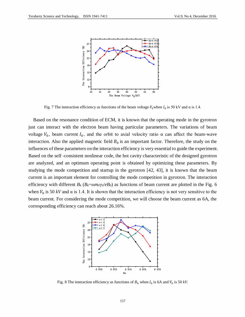
Fig. 7 The interaction efficiency as functions of the beam voltage 𝑉0when 𝐼0 is 50 kV and α is 1.4.
Based on the resonance condition of ECM, it is known that the operating mode in the gyrotron
just can interact with the electron beam having particular parameters. The variations of beam
voltage 𝑉0 , beam current 𝐼0 , and the orbit to axial velocity ratio α can affect the beam-wave
interaction. Also the applied magnetic field 𝐵0 is an important factor. Therefore, the study on the
influences of these parameters on the interaction efficiency is very essential to guide the experiment.
Based on the self -consistent nonlinear code, the hot cavity characteristic of the designed gyrotron
are analyzed, and an optimum operating point is obtained by optimizing these parameters. By
studying the mode competition and startup in the gyrotron [42, 43], it is known that the beam
current is an important element for controlling the mode competition in gyrotron. The interaction
efficiency with different Bk (Bk=ωm0γ0/eB0) as functions of beam current are plotted in the Fig. 6
when 𝑉0 is 50 kV and α is 1.4. It is shown that the interaction efficiency is not very sensitive to the
beam current. For considering the mode competition, we will choose the beam current as 6A, the
corresponding efficiency can reach about 26.16%.
Fig. 8 The interaction efficiency as functions of 𝐵𝑘 when 𝐼0 is 6A and 𝑉0 is 50 kV.
Terahertz Science and Technology, ISSN 1941-7411 Vol.9, No.4, December 2016
158
In the experiment, the beam voltage is an important factor to be adjusted for obtaining stable
operating status. The simulations on the interaction efficiency as functions of beam voltage are
plotted in Fig.7. It is found that the efficiency is relative sensitive to the beam voltage. The
maximum efficiency reaches about 26.12 % at beam voltage of 50 kV when 𝐵𝑘 is 0.972, 𝐼0 is 6 A
and α is 1.4. The interaction efficiency of TE17.4 varying with 𝐵𝑘 is also plotted in Fig. 8. At the
same beam voltage, it is obvious that the interaction efficiency is very sensitive with the magnetic
field. The interaction efficiency drops very fast when the magnetic field deviates from the best
value. And the magnetic field of maximum interaction efficiency increases when enhancing the
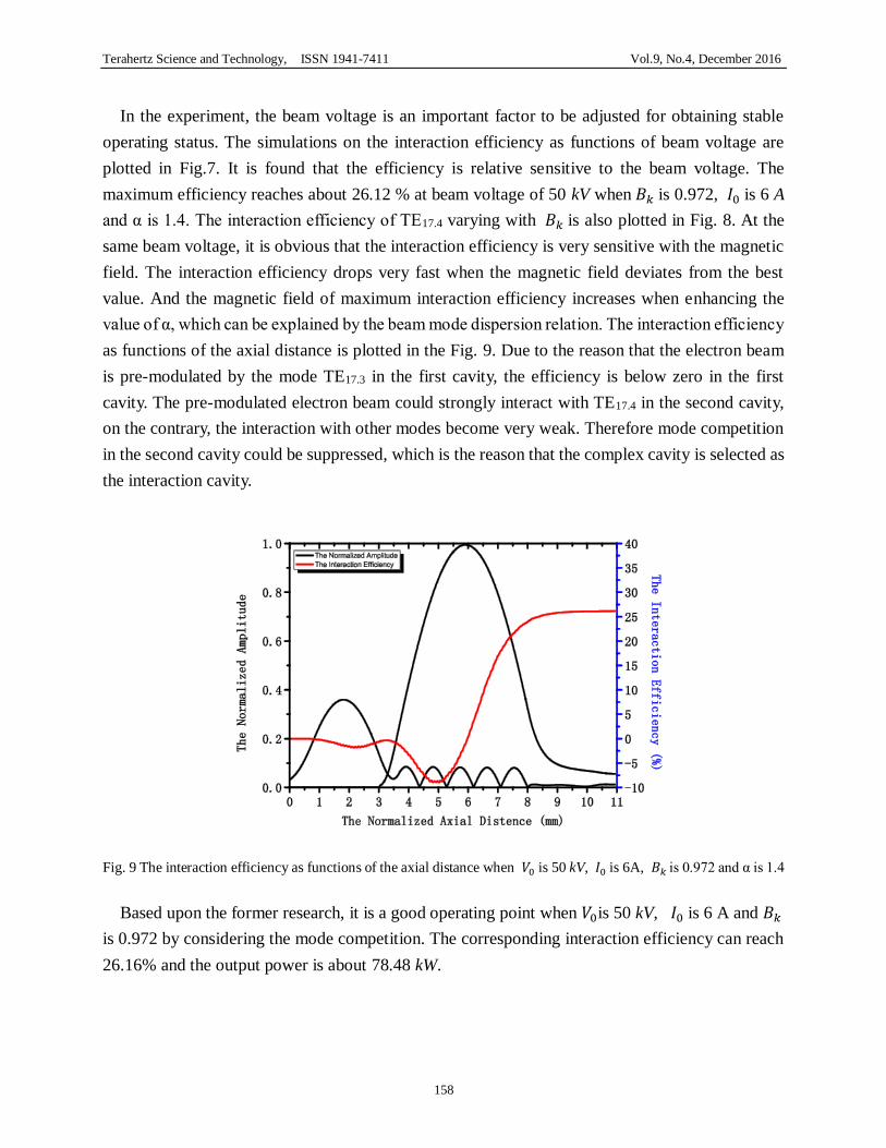
value of α, which can be explained by the beam mode dispersion relation. The interaction efficiency
as functions of the axial distance is plotted in the Fig. 9. Due to the reason that the electron beam
is pre-modulated by the mode TE17.3 in the first cavity, the efficiency is below zero in the first
cavity. The pre-modulated electron beam could strongly interact with TE17.4 in the second cavity,
on the contrary, the interaction with other modes become very weak. Therefore mode competition
in the second cavity could be suppressed, which is the reason that the complex cavity is selected as
the interaction cavity.
Fig. 9 The interaction efficiency as functions of the axial distance when 𝑉0 is 50 kV, 𝐼0 is 6A, 𝐵𝑘 is 0.972 and α is 1.4
Based upon the former research, it is a good operating point when 𝑉0is 50 kV, 𝐼0 is 6 A and 𝐵𝑘
is 0.972 by considering the mode competition. The corresponding interaction efficiency can reach
26.16% and the output power is about 78.48 kW.

Terahertz Science and Technology, ISSN 1941-7411 Vol.9, No.4, December 2016
159
Fig. 10 Basic schematic of a double-anode MIG.
Fig. 11 The schematic configuration of the double-anode MIG and the electron trajectories
Fig. 12 The distribution of equipotential line at cathode region
V. The magnetron injection gun (MIG) for 0.42 THz gyrotron
Based on the tradeoff equations [42-44], combining to the requirement of the interaction
parameters, the initial structure of the electron gun is obtained. According to a large number of
simulations by the electron trajectory PIC code (CHIPIC), the MIG has been simulated and
optimized. When the interaction magnetron 𝐵0 is 8.012 T, anode voltage 𝑉0 is 50 kV, operating

Terahertz Science and Technology, ISSN 1941-7411 Vol.9, No.4, December 2016
160
current 𝐼0 is 6 A, a good quality electron gun with maximum transverse velocity spread of 3.19%,
and the ratio of the transverse velocity to the axial velocity of 1.4 is obtained. The optimized
parameters for the 0.42 THz second harmonic gyrotron are shown in table II, and the electron beam
trajectory, the distribution of equipotential line at cathode region and the velocity of beam are
shown in figure 11 to figure 14.
Fig. 13 The axial velocity of the electron beam
Fig. 14. The ratio of the transverse velocity to the axial velocity alpha
TAB. II THE REQUIREMENTS OF THE ELECTRON BEAM PARAMETERS FOR 0.42 THZ SECOND HARMONIC GYROTRON
V0 50 kV Electron guiding center radius rg 1.95 mm
I0 5.5 A Transverse to axial velocity ratio α 1.4
B0 8.012 T The operating frequency f0 0.42 THz
TAB. III OPTIMIZED DESIGN PARAMETERS OF DOUBLE-ANODE MIG FOR 0.42 THZ SECOND
HARMONIC GYROTRON
Magnetic compression ratio 30 Radius of the cathode 9.1 mm
Maximum transverse velocity spread 3.19 % Cathode slant angle ϕc 35º
Maximum axial velocity spread 5.123 % Emitter length ls 1.6 mm
Cathode/control-anode distance 7.3 mm Electron guiding center radius rg 1.95 mm
Beam thickness at interaction region 0.379 mm Beam current density 4.9 A/cm2

Terahertz Science and Technology, ISSN 1941-7411 Vol.9, No.4, December 2016
161
VI. The mode competition in the designed complex cavity gyrotron
We derive the following system of equations from the system of self-consistent field equations
consisting of the Maxwell equations and the equations of motion of the electrons using the
averaging methods [45, 46]:
𝑑𝐹𝑛
𝑑𝑡= 𝛷𝑛
′ − 𝐹𝑛 𝜔𝑛 2𝑄𝑛⁄ (10)
𝑑𝛹𝑛
𝑑𝑡= 𝛷𝑛
′′ 𝐹𝑛⁄ + (�̃�𝑛′ − 𝜔𝑛) (11)
where 𝐹𝑛 is the time-dependent amplitude of the 𝑛𝑡ℎ mode, which varies slowly with the time 𝑡,
𝛹𝑛 is the corresponding phase. �̃�𝑛′ = �̃�𝑛,𝑟
′ + 𝑗 �̃�𝑛,𝑟′ 2𝑄𝑛⁄ is the cold cavity resonant
frequency, 𝜔𝑛 is the reference frequency, which is very close to the real part of the cold resonant
frequency �̃�𝑛,𝑟′ . Here Φ𝑛 = 𝛷𝑛
′ + j𝛷𝑛′′ , which characterizes the intensity of interaction of the
electron beam and the high-frequency field of this mode.
First, we study the mode competition in the designed gyrotron with an ideal electron beam when
the gyrotron is at the candidate operating point. The corresponding results are shown in Fig.15. It
is shown that the designed gyrotron can stably operate at the pair of the operating modes TE-17.3/TE-
17.4, and other competing modes including the second harmonic modes and the fundamental modes
are well suppressed during the gyrotron reach the steady state. Since TE-17.3 is used to modulate
the electron beam at the first cavity, thus its amplitude is much larger than the amplitudes of the
competing modes, but it is still lower than that of TE-17.4.
Fig. 15 The normalized amplitude |𝐹𝑛| in various mode vs time calculated by the time dependent, multi-mode
nonlinear theory in the designed complex cavity gyrotron when 𝑉0 is 50 kV, 𝐼0 is 6 A, α is 1.4, and 𝐵𝑘 is
0.972.

Terahertz Science and Technology, ISSN 1941-7411 Vol.9, No.4, December 2016
162
Fig. 16 The normalized amplitude |𝐹𝑛| in various mode vs time calculated by the time dependent, multi-mode
nonlinear theory in the designed complex cavity gyrotron when 𝑉0 is 50 kV, 𝐼0 is 6 A, α is 1.4, and 𝐵𝑘 is
0.972 (the beam width is 0.195 mm, and the electron velocity spread is 5 %).
Meanwhile, the quality of the electron beam should be considered in the simulation. Because the
real electron beam emitted from magnetron injection gun (MIG) has finite width and velocity
spread. It is known that the electron velocity spread and the finite width of the electron beam not
only deteriorate the gyrotron efficiency, but also influence the mode interaction. Thus it is
necessary to investigate the effects of the electron velocity spread and the finite width of the
electron beam on the mode competition in the designed gyrotron. The investigation on the influence
of the electron velocity spread is shown in Fig. 16, where the electron velocity spread is 5 % and
the operating point is the same as in Fig.15. It is found that the dependence of amplitude on the
velocity spread is very weak for the operating mode TE-17.4. The reason is that Doppler shift is
negligible in the cavity for the stationary gyrotron oscillation with an almost zero axial wave
number. Then, the weak dependence of power on the electron velocity spread is observed. However,
it is also shown that the electron velocity spread greatly affects some competing modes like TE-14.5
and TE7.3. The amplitudes of TE-14.5 and TE7.3 both reach about 10-6, which can be explained by
resonance condition for ECM.
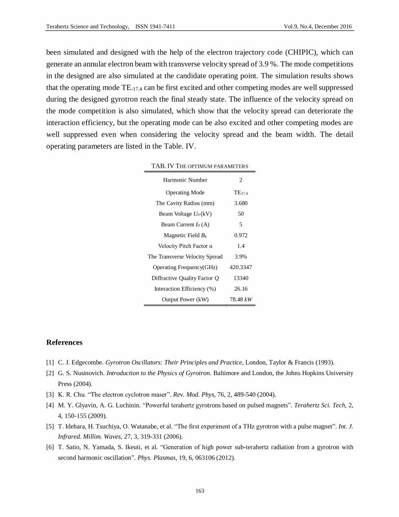
VII. The design scheme for 0.42 THz gyrotron
Based upon former investigations, a complex cavity gyrotron has been designed. The linear and
nonlinear analysis show that the designed gyrotron can operate stably at TE17.4 with power of
78.48 kW when U0 is 50 kV, I0 is 6 A and Bk is 0.972. The corresponding interaction efficiency can
reach 26.16%. Combining the hot-cavity simulation, a double-anode magnetron injection gun has
Terahertz Science and Technology, ISSN 1941-7411 Vol.9, No.4, December 2016
163
been simulated and designed with the help of the electron trajectory code (CHIPIC), which can
generate an annular electron beam with transverse velocity spread of 3.9 %. The mode competitions
in the designed are also simulated at the candidate operating point. The simulation results shows
that the operating mode TE-17.4 can be first excited and other competing modes are well suppressed
during the designed gyrotron reach the final steady state. The influence of the velocity spread on
the mode competition is also simulated, which show that the velocity spread can deteriorate the
interaction efficiency, but the operating mode can be also excited and other competing modes are
well suppressed even when considering the velocity spread and the beam width. The detail
operating parameters are listed in the Table. IV.
TAB. IV THE OPTIMUM PARAMETERS
Harmonic Number 2
Operating Mode TE17.4
The Cavity Radius (mm) 3.680
Beam Voltage U0 (kV) 50
Beam Current I0 (A) 5
Magnetic Field Bk 0.972
Velocity Pitch Factor α 1.4
The Transverse Velocity Spread 3.9%
Operating Frequency(GHz) 420.3347
Diffractive Quality Factor Q 13340
Interaction Efficiency (%) 26.16
Output Power (kW) 78.48 kW
References
[1] C. J. Edgecombe. Gyrotron Oscillators: Their Principles and Practice, London, Taylor & Francis (1993).
[2] G. S. Nusinovich. Introduction to the Physics of Gyrotron. Baltimore and London, the Johns Hopkins University
Press (2004).
[3] K. R. Chu. “The electron cyclotron maser”. Rev. Mod. Phys, 76, 2, 489-540 (2004).
[4] M. Y. Glyavin, A. G. Luchinin. “Powerful terahertz gyrotrons based on pulsed magnets”. Terahertz Sci. Tech, 2,
4, 150-155 (2009).
[5] T. Idehara, H. Tsuchiya, O. Watanabe, et al. “The first experiment of a THz gyrotron with a pulse magnet”. Int. J.
Infrared. Millim. Waves, 27, 3, 319-331 (2006).
[6] T. Satio, N. Yamada, S. Ikeuti, et al. “Generation of high power sub-terahertz radiation from a gyrotron with
second harmonic oscillation”. Phys. Plasmas, 19, 6, 063106 (2012).

Terahertz Science and Technology, ISSN 1941-7411 Vol.9, No.4, December 2016
164
[7] E. M. Choi, C. D. Marchewka, I. Mastovsky, et al. “Experimental results for a 1.5 MW, 110 GHz gyrotron
oscillator with reduced mode competition”. Phys. Plasmas, 13, 2, 023103 (2006).
[8] Y. Tatematsu, Y. Yamaguchi, T. Idehara “Development of a kW Level-200 GHz gyrotron FU CW GI with an
internal quasi-optical mode convertor”. Int. J. Infrared. Millim. Waves., 33, 3, 292-305 (2012).
[9] Ruifeng. Pu, G. S. Nusinovich, O. V. Sinityn, et al. “Numerical study of efficiency for a 670 GHz gyrotron”. Phys.
Plasmas., 18, 2, 023107 (2011).
[10] T. Satio, Y. Tatematsu, Y. Yamaguchi, et al. “Observation of dynamic interactions between fundamental and
second-harmonic modes in a high-power sub-terahertz gyrotron operating in regimes of soft and hard self-
excitation”. Phys. Rev. Lett., 109, 15, 155001 (2012).
[11] V. S. Bajaj, C. T. Farrar, M. K. Hornstein, et al. “Dynamic nuclear polarization at 9 T using a novel 250 GHz
gyrotron microwave source”. Magn. Reson, 160, 2, 85-90 (2003).
[12] D. Van der Weide. “Applications and outlook for electronic terahertz technology”. Opt. Photon. News, 14, 4, 48-
53 (2003).
[13] F. C de Lucia. “Science and technology in the submillimeter region”. Opt. Photo. News, 14, 8, 44-50 (2003).
[14] D. Mittleman. Sensing With Terahertz Radiation. Berlin, Germany: Springer-Verlag (2003).
[15] P. F. Taday. “Applications of terahertz spectroscopy to pharmaceutical sciences”. Phil. Trans. R. Soc. Lond. A.,
362, 351–364 (2004).
[16] J. Zmuidzinas and P. L. Richards. “Superconducting detectors and mixers for millimeter and submillimeter
astrophysics”. Proc. IEEE, 92, 1597–1616 (2004).
[17] Y. C. Shen, T. Lo, P. F. Taday, et al. “Detection and identification of explosives using terahertz pulsed
spectroscopic imaging”. Appl. Phys. Lett., 86, 241116 (2005).
[18] R. Appleby and H. B. Wallace. “Standoff detection of weapons and contraband in the 100 GHz to 1 THz region”.
IEEE J. Antennas Propag., 55, 2944–2956 (2007).
[19] M. Tonouchi. “Cutting-edge terahertz technology”. Nat. Photonics. 1, 2, 97-105 (2007).
[20] V. L. Granatstein and G. S. Nusinovich. “Detecting excess ionizing radiation by electromagnetic breakdown of
air”. J. Appl. Phys., 108, 6, 063304 (2010).
[21] B. B. Jin, C. L. Zhang, P. H. W, et al. “Recent progress of terahertz spectroscopy on medicine and biology in
China”. Terahertz Sci. Tech, 3, 4, 192-200 (2010).
[22] H. B. Wallace. “Analysis of RF imaging applications at frequencies over 100 GHz”. Appl. Opt., 49, E38–E47
(2010).
[23] V. L. Bratman, M. Y. Glyavin, K. Kalynov, et al. “Terahertz gyrotrons at IAP RAS: status and new designs”. J.
Infrared. Milli. Terahz. Waves. 32, 371-379 (2011).
[24] M. Yu. Glyavin, A. G. Luchinin, G. S. Nusinovich, et al. “A 670 GHz gyrotron with record power and efficiency”.
Appl. Phys. Lett., 101, 15, 153503 (2012).
[25] N. Ohyabu, T. Morisaki, S. Masuzaki, et al. “Observation of Stable Superdense Core Plasmas in the Large Helical
Device”. Phys. Rev. Lett., 97, 5, 055002 (2006).
[26] T. Notake, T. Saito, Y. Tatematsu, et al. “Subterahertz gyrotron developments for collective Thomson scattering
in LHDa”. Rev. Sci. Instrum. 79, 10, 10E732 (2008).

Terahertz Science and Technology, ISSN 1941-7411 Vol.9, No.4, December 2016
165
[27] K. J. Kim, M. E. Read. “Design considerations for a megawatt CW gyrotron”. Int. J. Electronics, 51, 4, 427-445
(1981).
[28] A. V. Gapanov, V. A. Flaygin, A. L. Gol'denberg, et al. “Powerful millimeter-wave gyrotrons”. Int. J. Electronics,
51, 4, 277-305 (1981).
[29] K. L. Felch, R. E. Bier, L. J. Craig, et al. “The 140 GHz gyrotron development program”. Quarterly Report No. 4,
January-March (1985).
[30] Y. Carmel, A. K Ganguly, D. Dialetis, et al. “A high power complex cavity gyrotron for fusion research devices”.
IEEE Electron Devices Conference, 372-374 (1982).
[31] K. Felch, R. Bier, L. Fox, et al. “A 60 GHz, 200 kW CW gyrotron with a pure output mode”. Int. J. Electron., 57,
6, 815-820 (1984).
[32] G. V. Pavel’ev, Sh. E. Tsimring, and V. E. Zapevalov. “Coupled cavities with mode conversion in gyrotrons”. Int.
J. Electron., 63, 3, 379-391 (1987).
[33] E. Borie, B. Jödicke, H. Wenzelburger, et al. “Resonator design studies for a 150 GHz gyrotron at KfK”. Int. J.
Electron., 64, 1, 107-126 (1988).
[34] A. W. Fliflet, R. C. Lee, and M. E. Read. “Self-consistent field model for the complex cavity gyrotron”. Int. J.
Electron., 65, 3, 273-283 (1987).
[35] O. Dumbrajs, and E. Borie. “A complex cavity with mode conversion for gyrotrons”. Int. J. Electron., 65, 3, 285-
295 (1987).
[36] Y. Huang, H. F. Li, Sh. W. Yang, et al. “Study of a 35-GHz third-harmonic low-voltage complex cavity gyrotron”.
IEEE Trans. Plasma Sci. 27, 2, 368-373 (1999).
[37] Y. Huang, H. F. Li, P. Z. Du, et al. “Third-harmonic complex cavity gyrotron self-consistent nonlinear analysis”.
IEEE Trans. Plasma Sci. 25, 6, 1406-1411 (1997).
[38] H. F. Li, Zh. L. Xie, W. X. Wang, et al. “A 35-GHz low-voltage third-harmonic gyrotron with a permanent magnet
system”. IEEE Trans. Plasma Sci, 31, 2, 264-271 (2003).
[39] Sh. Yu, H. F. Li, Z. L. Xie, et al. “A nonlinear analysis on 8 mm band third-harmonic complex cavity gyrotron
with gradual transition”. Acta. Phys. Sin., 50, 10, 1979-1983 (2001).
[40] Sh. Yu, F. L. Li, Z. L. Xie, et al. “A nonlinear simulation on beam-wave interaction for high-harmonic complex
cavity gyrotron with radial transition”. Acta. Phys. Sin., 49, 12, 2455-2459 (2000).
[41] X. J. Niu, and L. G. “Experiment of 94 GHz, CW, low-voltage gyrotron”. in Proc. 13th IEEE Int. Vacuum
Electronics Conference and 9th IEEE Int. Vacuum Electron Sources (2012).
[42] W. Lawson. “Magnetron Injection Gun Scaling”. IEEE Trans. Plasma Sci. 16, 2 (1988).
[43] J. M. Baird, W. Lawson. “Magnetron injection gun (MIG) design for gyrotron applications”. Int. J. Electron., 61,
6, 953-967 (1986).
[44] W. Lawson, and V. Specht. “Design comparison of single anode and double anode 300-MW magnetron injection
gun”. IEEE Trans. Electron Devices, 40, 7, 1322-1328 (1993).
[45] B. Levush, T. M. Antonsen, Jr. “Mode competition and control in high-power gyrotron oscillators”. IEEE Trans.
Plasma. Sci., 18, 3, 260-272 (1990).
[46] G. S. Nusinovich, M. Yeddulla, T. M. Antonsen, Jr., et al. “Start-up scenario in gyrotrons with a nonstationary
microwave-field structure”. Phys. Rev. Lett., 96, 125101 (2006).