the theory and practice of energy saving in the chemical...
TRANSCRIPT
Energy 28 (2003) 55–97www.elsevier.com/locate/energy
The theory and practice of energy saving in the chemicalindustry: some methods for reducing thermodynamic
irreversibility in chemical technology processes
I.L. Leitesa,∗, D.A. Samab, N. Lior c
a State Institute for Nitrogen Industry (GIAP),12–84 Donetskaya Street, 109652 Moscow, Russiab University of Massachusetts Lowell, Chemical Engineering Department, Lowell, MA 01854, USA
c University of Pennsylvania, Department of Mechanical Engineering & Applied Mechanics, Philadelphia,PA 19104-6315, USA
Received 29 April 1999
Abstract
The causes of thermodynamic irreversibility in chemical reactions and other industrial chemical processes(in particular absorption, stripping, and heat transfer) and ways of reducing energy consumption have beenexamined. Some thermodynamic principles based on the Second Law of thermodynamics such as the socalled “counteraction principle,” “driving force method,” “quasi-static method,” and the result some ofpractical methods for energy saving design are discussed. It is demonstrated that the possibilities for reduc-ing energy consumption are substantially higher than often seems possible. The correctness and practicaleffectiveness of the above methods have been confirmed by many commercial examples, for instance thelead author was able to reduce heat consumption in more than 20 commercial CO2 removal installationsby changes in networks only, without changing the absorbent. The heat consumption was reduced to about1/2 to 1/3 of that used with conventional flow sheets. 2002 Published by Elsevier Science Ltd.
1. Introduction.
The purpose of this paper is to counter the widespread viewpoint that thermodynamic irreversi-bility in processes involving chemical reactions ostensibly is inevitable and results in large energyresource losses [1]. It seems to the authors that this misconception and the lack of understanding
∗ Corresponding author. Tel.:+7-095-357-70-16; fax+7-095-916-60-25.E-mail address: [email protected] (I.L. Leites).
0360-5442/03/$ - see front matter 2002 Published by Elsevier Science Ltd.PII: S0360-5442(02)00107-X

56 I.L. Leites et al. / Energy 28 (2003) 55–97
Nomenclature
C specific heat capacity;E, e Exergy;�Ech change in “chemical” exergy;�Ep change in “pressure” exergy;�Et change in “ thermal” exergy;Fh area of heat transfer or mass transfer;G Gibbs energy, molar or volume flow rate;Gi � mi partial molal Gibbs energy, chemical potential of i-component;H, Hi enthalpy, partial molal enthalpy;Ke chemical equilibrium constant;Kh, Km heat transfer rate coefficient, mass transfer rate coefficient;N quantity of moles;L quantity of liquid;M mass flow rate;P pressure;P∗
i partial equilibrium pressure;Q quantity of substance mole/hour, kg/hour or m3/hour;R universal gas constant;S, Si entropy, partial molal entropy;T Temperature;T0 ambient temperature;V Volume;W useful work;Xi, concentration of i component in liquid;�Y the process driving force in any form;Yi concentration of i component in gas mixture;he exergetic efficiency;� reflux ratio for stripping;
Subscripts
Rev Reversible.
by many process designers of the Second Law methods for reducing exergy losses1 are the maincauses of non-optimal designs with excessive energy consumption.
Energy resource consumption has been shown to be the principal cost of many energy-intensivechemical processes, such as ammonia production [2–4]. As a result, the aim of modern energy-
1 To clarify, we note that different terms are used in the literature for exergy changes, such as exergy losses, expenditures,

57I.L. Leites et al. / Energy 28 (2003) 55–97
intensive process design has been to reduce energy consumption [2–6]. In addition, as will beshown below, a reduction in energy consumption often results in a simultaneous decrease (notan increase) in capital cost.
In our opinion, most of the ideas in this report are so simple and evident that they should beof common knowledge to chemical process designers. It is thus difficult to understand why text-books and monographs [7–12] don’ t present, in systematic form, the known rules for savingenergy in the design of chemical processes. There are, however, many published papers that aredevoted to the use of the Second Law for the reduction of energy consumption [13–23]. In parti-cular, the ideas expressed in [19,20] are closest to the approach used in this paper. The theoreticalbasis is given by the well-known exergy method [10–12].
This paper is based partly on the senior author’s book [24] and papers in [25–28] as well ason the many publications of different scientists. We would like to draw particular attention to themany excellent papers of Petliuk and Platonov devoted to energy saving chemical rectificationdesigns, published as far back as 1964 [29,30].
2. Some thermodynamic fundamentals of energy saving in the chemical industry
2.1. Thermodynamic reversibility and the driving force of chemical processes
Thermodynamic reversibility requires that all process driving forces, such as temperature, press-ure and chemical potential differences be zero at all points and times. Thus, the theoretical thermo-dynamically reversible chemical process must proceed along an equilibrium line that is in chemi-cal equilibrium at each point of a reactor. Accordingly, the driving force for the process must bezero throughout the entire process: not just at the end. Such a theoretical process results in theproduction of the maximal amount of useful work, or in the consumption of the minimal amountof work.
Unfortunately, a reversible chemical process operates at an infinitesimal rate, and requires aninfinitely large plant. To operate a chemical process in finite time and at finite cost, it is necessaryto have finite driving forces, i.e., to expend some thermodynamic availability (exergy) and, as aresult, to consume energy resources. The goal of the process designer is to expend this thermodyn-amic availability wisely while achieving the technological goals of the process. Too large a drivingforce expends more exergy than is necessary and wastes our energy resources, while too small adriving force requires excessive capital investment. In particular, the designer should avoid anapparatus that has too large a driving force in one part, and too small a driving force in anotherpart. In such a case, both energy resources and capital are wasted.
The classical example of the thermodynamically reversible operation of chemical reactions is
consumption, and destruction. We note that exergy expenditure in one part of a more complex system may be used to good advantagein another part of the system, or used to reduce capital costs, or used to provide a useful product outside the system. In accordwith the objective of this paper to improve energy saving practices in industrial processes, we would most often use the termexergy expenditure.

58 I.L. Leites et al. / Energy 28 (2003) 55–97
the van’ t Hoff ideal-gas reaction equilibrium chamber [9], Fig. 1. This example has been usedas a method for deducing the concept of the equilibrium constant. This model can also be usedto derive the expression for the maximal useful work that can be produced as a result of a reaction.The chamber contains an equilibrium mixture of reaction components. Additional quantities ofraw materials are supplied by transport through semi-permeable membranes, infinitely slowlyand with infinitesimally small changes in pressure, concentrations and temperatures. The reactionproducts are removed in the same manner.
The maximal work Wrev associated with such a chemical reaction, say specifically the reactionshown in Fig. 1
nA � mB � hC � jD (1)
carried out at constant temperature and pressure, can be expressed as
�Wrev,P,T � ��G � RT�lnKe�lnPh
C1PjD1
PnA1Pm
B1
�� � �(�H�T�S) � 0 (2)
The Gibbs energy (G) always decreases during a spontaneous chemical reaction, and the maxi-mal obtainable work is equal to the decrease in Gibbs energy at the P and T of the reaction2.
Our task is to use this change in Gibbs energy to recover the useful work to maximal extent,or, as will be shown later, to reduce the magnitude of the Gibbs energy change where possible.
As stated earlier, if a chemical reaction could be carried out reversibly, the process wouldproduce the maximum quantity of useful work. To produce finite changes in a finite time, it is
Fig. 1. A van’ t Hoff reaction chamber [9]
2 To expedite the analysis, we have focused on spontaneous reactions. That is, reactions running with a decrease of Gibbs energyand consequently with the possibility of obtaining useful work. For non-spontaneous reactions, which proceed with an increase inGibbs energy, it is necessary to spend work to run them. One energy-saving possibility is to carry out such reactions by combiningthem together with spontaneous reactions. [31].

59I.L. Leites et al. / Energy 28 (2003) 55–97
necessary, however, to have finite driving forces. Therefore, all actual processes, chemical orotherwise, must operate in a thermodynamically irreversible way.
The generalized driving force in a chemical reaction is the difference in partial Gibbs energies,i.e. chemical potentials:
Gi � mi � Hi�TSi (3)
The actual process driving forces are the differences in partial pressures �Pi, concentrations�xi,�yi and temperatures �T.
Since chemical reactions are carried out irreversibly, a considerable part of the Gibbs energychange may not be utilized. It was mentioned above that there is a widespread misconceptionthat these losses are large and inevitable [1]. We will show here that there are many technicalmethods for reducing the thermodynamic irreversibility of chemical reactions, as well as of massand heat transfer processes.
We will first consider the expansion, from P1 to P2, of a compressed gas in a cylinder, asshown in Figs. 2 and 3 [7]. This is the mechanical equivalent of a spontaneous chemical reaction.
Fig. 2a represents the expansion against a counteracting external pressure that is continuouslyadjusted to precisely match the pressure of the gas in the cylinder as the gas expands from P1 toP2. The driving force for the expansion is zero at all points; thus, the process is reversible andthe work recovered is the maximum possible. This reversible work is represented by the areaunder the P1P2 curve in Fig. 3. However, since the driving force is zero, such an expansion wouldtake an infinite time and is not possible.
Another type of expansion is shown in Fig. 2b, where the gas expands against the constant
Fig. 2. Reversible and irreversible expansion work of a compressed gas [7]. (a) Reversible expansion WR � �2
1
PdV;
(b) Irreversible expansion WIR � PS(V2�V1)

60 I.L. Leites et al. / Energy 28 (2003) 55–97
Fig. 3. Graphical integration of reversible and irreversible work [7].WR=Area V1P1P2V2;WIR=Area V1PSPS’V2
pressure of the surroundings, PS, which is lower than P1 or P2. Since the driving force for theexpansion, (PGAS–PS), is finite, the expansion is irreversible, but can proceed in a finite time. Thework obtained, shown in Fig. 3 as the dark shaded area under the PS line, is clearly less than thereversible work.
It is easily seen from Fig. 3, that the amount of work obtained from this irreversible expansioncan be increased by increasing the counteracting pressure above the pressure of the surround-ings, PS.
If the counteracting pressure is increased beyond P2, the gas cannot expand fully to V2, but,depending on the geometry of the curves, the work obtained may continue to increase. Of course,if the counteracting pressure is increased further all the way to P1 (the initial pressure of thecompressed gas), the gas cannot expand at all and no work will be obtained. Thus, we see thatthere is an optimal value of counteracting pressure, somewhere between the pressure of the sur-roundings (PS) and the initial pressure of the gas (P1) that produces the maximum work for theirreversible expansion of the gas against a single counteracting pressure.
Analogously, it is clear from Fig. 3 that it is possible to use multiple stages of constant counter-acting pressures to further increase the expansion work, and that the maximum value of workobtainable increases as the number of stages increases.
Thus, though it is never possible to recover the entire theoretical reversible expansion work, itis possible by proper design and operation to maximize the work obtained (i.e., minimize theexergy loss) for a given, or revised, expansion scheme.
Though the following discussion deals only with the expansion of a compressed gas, the con-clusions for saving energy are of general applicability. Process energy can be saved by:
1. Applying a counteraction to reduce the driving force2. Optimizing the process conditions3. Using multiple stages
61I.L. Leites et al. / Energy 28 (2003) 55–97
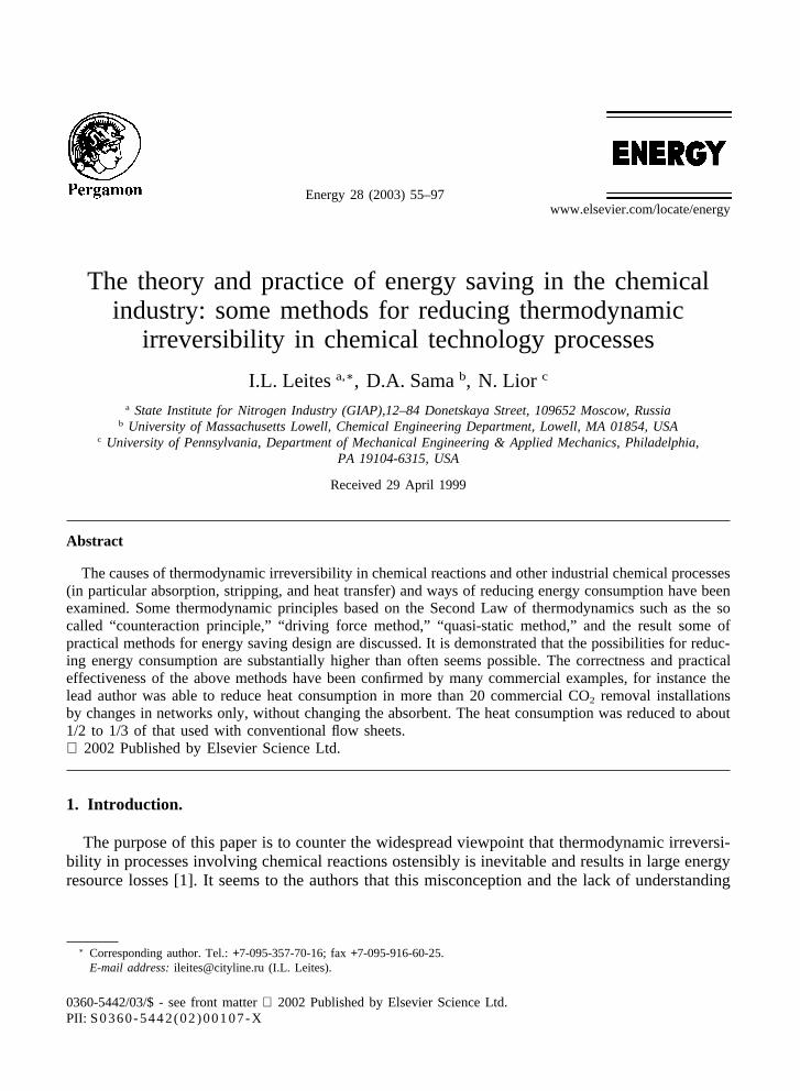
Fig. 4. The conventional task of optimum area of heat exchanger.1—Energy consumption cost; 2—Investment cost;3—Sum of costs.
4. Other methods, as described later in this paper
It will also be shown that, analogously, there are optimal pressures, temperatures and reactantratios for chemical reactions, corresponding to the minimal specific exergy losses, i.e., the exergyoptimum for a given process flow sheet [26].
It is important to recall that there is a well-known conflict between our desire to reduce energyconsumption (that is to reduce the driving force) and the opposite wish to increase the drivingforce in order to increase the rate of the process and, thereby, to decrease the capital investment.A balance between these two effects produces an economic optimum (see Fig. 4), but it isimportant to pay attention to some other aspects of conventional cost optimizations.
The monetary cost of energy resources used is based on the current market price for energy.Typically nowadays, monetary costing neglects the costs of current as well as future environmentaland ecological problems for the country and the world.
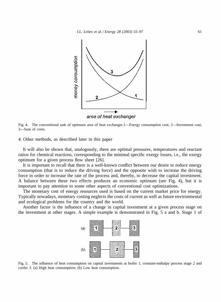
Another factor is the influence of a change in capital investment at a given process stage onthe investment at other stages. A simple example is demonstrated in Fig. 5 a and b. Stage 1 of
Fig. 5. The influence of heat consumption on capital investments at boiler 1, constant-enthalpy process stage 2 andcooler 3. (a) High heat consumption; (b) Low heat consumption.

62 I.L. Leites et al. / Energy 28 (2003) 55–97
this process is a boiler that produces steam for use in stage 2, which is a constant-enthalpy process(such as a distillation column which generally operates with essentially no enthalpy differencebetween feed and products). According to the First Law of thermodynamics, the heat producedat stage 1 and fed to the constant-enthalpy stage 2, is removed at stage 3—a cooler that generallydischarges heat to the ambient. It is now assumed that the relative capital cost investments in thethree stages of this process are depicted as in Fig. 5 a. If the driving force and energy consumptionat stage 2 are reduced, the capital investment there is increased (in a distillation column this couldbe done by increasing the number of plates), as shown in Fig. 5 b. However, the capital investmentat both stages 1 and 3 will be reduced because the amount of heat which needs to be suppliedby the boiler and removed by the cooler is consequently decreased. In such cases, it may bepossible to reduce both energy consumption and investment costs simultaneously.
There are other ways to reduce exergy losses and total investments simultaneously. Comparethe simple examples of heat transfer with an extremely non-uniform �T driving force (Fig. 6 b),with that of a uniform driving force (Fig. 6 a). Due to the near-zero �T driving force at the rightend of the heat exchanger in Fig. 6 b, the logarithmic mean driving force is near zero, and theheat exchange area must thus be very large. Furthermore, due to the large driving force at theleft end of the exchanger, the exergy loss in the case of Fig. 6 b is also large because it isproportional to the large area between the two temperature profile lines.
The use of a uniform driving force (Fig. 6 a) allows, however, a reduction in exergy losses aswell as a reduction of heat exchanger area. In general, changes in flow sheets that make drivingforces more uniform can simultaneously reduce both exergy losses and capital investments.
Similarly, with chemical reactions, a chemical engineer may want to reach equilibrium at theexit of a reactor (state 2, Fig. 7). But if attention is not paid to the large driving force at thereactor inlet (state 1), irreversibility and exergy losses may be excessive. At the same time, sincethe mean driving force towards state 2 in this reactor is near zero, the reactor size and cost mayalso be excessive.
A general conclusion is that the art of the energy saving chemical engineer is to make drivingforces small and uniform.
This issue is analyzed in more detail below.
Fig. 6. The temperatures of streams during heat exchange a) The uniform driving force; b) The nonuniform drivingforce.

63I.L. Leites et al. / Energy 28 (2003) 55–97
Fig. 7. The classical example of thermodynamically irreversible way of chemical reaction.y—concentration of areagent; y∗—equilibrium concentration; 1—input of reagents; 2—outlet of reagents.
2.2. The Le Chatelier principle3 and the “counteraction principle”
At first glance, the demands of the Second Law generate diametrically opposite consequencesfor the chemist-technologist and for the power engineer [26]. The chemist-technologist would liketo increase the extent of reaction and, as a result, the yield of useful products. He/she wants,consequently, to increase the driving force of the process, i.e. to increase the absolute value ofthe decrease in Gibbs energy, –�G. The classical Le Chatelier principle, which is a consequenceof the Second Law, deals with this matter and is thus employed. To increase the extent of reaction,the Le Chatelier principle requires a reduction in pressure for a reaction that operates with anincrease in volume, and an increase in pressure for reactions that operate with a decrease involume. These pressure changes increase the –�G driving forces, thus driving the reactions furthertowards completion.
Analogously, the Le Chatelier principle requires a reduction in the temperature of exothermicreactions, and an increase in the temperature of endothermic reactions. Furthermore, to increasethe yield of useful products, Le Chatelier’s principle recommends an excess of one of the reactants.
The power engineer, on the other hand, would like to reduce the thermodynamic losses byapplying a “counteraction” to reduce the magnitude of the –�G driving force: e.g., by increasingthe temperature of exothermic reactions; reducing the temperature of endothermic ones; increasingthe pressure of reactions that increase in volume; and reducing the pressure of reactions thatdecrease in volume.
The advanced process designer must try to integrate these opposite objectives. This would bepossible if the process could be run in a manner approaching those shown in Fig. 2 a, 3 and in
3 To be more succinct, the Le Chatelier–Braun principle can be formulated as follows [7,9]: “A system in chemical equilibriumattempts to counteract any change in pressure, temperature or composition” .

64 I.L. Leites et al. / Energy 28 (2003) 55–97
Fig. 8, where each process is run reversibly with a gradually decreasing counteraction such that�Gij→0 at all locations and times.
Let us analyze one of the examples of the opposite requirements of the Second Law, viz. theinfluence of the temperature on the technological and exergetical characteristics of an exother-mic reaction.
First we examine an exothermic reaction operating at a constant temperature. The Le Chatelierprinciple requires a decrease in temperature to increase the yield and, thus, to increase the amountof heat released. On the other hand, we see from the Carnot relation, Eq. (4), that the exergeticvalue of a unit of heat increases as the temperature increases,.
W � Q(1�T0 /T) (4)
where Q here is quantity of heat.Thus, it is clear that for a constant-temperature exothermic reaction there is an optimal reaction
temperature where the exergetic value of the heat released is maximal and, as a result, exergylosses are minimal. (This is discussed in more detail in Section 4 of this paper.)
However, instead of using a constant reaction temperature, the best way, in principle, is to varythe reaction temperature; start the reaction under the maximal temperature and then reduce itgradually, so that the reaction is complete at the reactor exit, (see Fig. 8 a). This method reducesthe –�G driving force along the entire length of the reactor: at the entrance due to the hightemperature, and at the exit due to the reduced concentration of the reactants. Thus, the heat ofreaction can be recovered with maximal efficiency, while simultaneously running the reaction tocompletion [26].
Fig. 8. Thermodynamic reversible ways of operating chemically reversible reactions by counteraction, that is withretarding, with maximal use of Gibbs energy and minimal energy consumption. a—exothermic reaction, b—endothermicreaction, c—reaction with volume increase, d—reaction with volume decrease.
65I.L. Leites et al. / Energy 28 (2003) 55–97
Correspondingly, endothermic reactions (Fig. 8 b) should be started at a minimal temperature,and then the temperature should be increased gradually. In this manner, the –�G driving forceis made low along the entire length of the reactor. It is noteworthy here that the initial heatrequired can be supplied as inexpensive low-temperature heat, while the more expensive highertemperature heat is needed only at the end, to run the reaction to completion.
Now we analyze chemical reactions that result in volume changes. The relationship betweenthe changes in volume, pressure and Gibbs energy is:
�∂(�G)∂P �
T
� �V (5)
Eq. (5) shows that for a reaction in which volume increases (�V�0), a decrease in pressure causesa further decrease in �G (i.e., an increase in the absolute value of –�G) and, accordingly, resultsin an increased product yield. Of course, this is exactly what the Le Chatelier principle predicts.
Unfortunately, the thermodynamic irreversibility, i.e., the exergetic loss, also increases with anincrease in the magnitude of the –�G driving force. Thus, if we operate this reaction at a constantlow pressure we can expect higher yields, but will also incur higher exergetic losses. Alternatively,if operated at a constant high pressure to reduce the exergetic losses, the yields are reduced.
The resolution of this conflict would be to run the reaction at a variable pressure as shown inFig. 8 c. Use a high pressure as a counteraction at the start, and then gradually lower the pressureas the reaction proceeds to a high yield at the end of the reactor. In this manner the reaction canproceed with a reduced –�G driving force at all points, i.e., a reduced exergetic loss, withoutsacrificing yield. In the limit, as ��G→0 at all locations and times, the reaction would be thermo-dynamically reversible.
This is completely analogous to the thermodynamically reversible expansion of a compressedgas, Fig. 2 a and 3.
Unfortunately, it would take an infinite time, even if it were possible to run the reaction at theappropriate continuously varying pressure. A compromise would be to run the reaction in a finitenumber of stages with each succeeding stage being at a lower pressure than the prior one. Thoughthis multi-stage process cannot be thermodynamically reversible, it would lead to reduced exerg-etic losses. In practice, however, such a multi-stage reaction is sometimes difficult to accomplish.Thus, we may be limited to a one-stage constant pressure reaction and, if so, our task is to tryto find the optimal process conditions. Note also that this is in accordance with our previousconclusion that there is an optimal pressure for the single-stage expansion of a gas.
At the beginning of the reaction, the conversion is near zero but the exergetic losses are a finitequantity. Therefore, at this point, the specific losses per unit of useful product are nearly infinite.If the reaction is carried out completely, the exergetic losses (reduction in Gibbs energy) aremaximal. Therefore, an optimal conversion and optimal pressure, corresponding to the minimalexergy consumption per unit of reaction product, must exist. Some examples will be discussedlater. It will be shown that the specific exergy loss per quantity of useful product is a goodcriterion for optimization (for the case when the capital costs are nearly constant and the influenceof the change of conditions on the other stage parameters is negligible).
For a reaction that decreases in volume, Eq. (5) shows that an increase in pressure increasesthe magnitude of the –�G driving force, thus, increasing both the conversion (as predicted bythe Le Chatelier principle) and the exergetic loss. For such a reaction to proceed in a thermodyn-

66 I.L. Leites et al. / Energy 28 (2003) 55–97
amically reversible fashion, the pressure should start low and increase with the conversion asshown in Fig. 8d. The same final pressure is achieved with less compressor work by shifting thecompression from the reactants (whose volume is larger) toward the products (whose volume issmaller). Similar arguments apply here as did in the preceding discussion of reactions that increasein volume. Here, however, the optimal pressure for a constant pressure reaction, may well be lessthan that suggested by the Le Chatelier principle.
Next we consider the effect of using an excess of one of the reactants to increase the yield ofuseful product. Unfortunately, increasing the excess of one reactant increases the magnitude ofthe –�G driving force, which thereby increases the exergy loss. In addition, there are exergylosses due to mixing that require the consumption of energy to separate the excess reactant fromthe products.
Rather than using an excess reactant, a better approach is to run the reaction to partial com-pletion and then to recycle the unreacted feedstock. This can be expedient in spite of the energycost of separating and recirculating the unreacted feedstock. This conclusion is in agreement withexergy analysis.
Accordingly, it is possible to say that when the well-known Le Chatelier principle (resultingfrom the Second Law) is used by chemists in order to run the reaction to completion, they areoften forgetting the opposite Second Law requirement (the “counteraction principle” ) needed toreduce the exergy consumption per unit of product.
At first glance, the “counteraction principle” appears to be a quasi “anti Le Chatelier principle”[25]. However, as we have shown here, both the “counteraction principle” and the Le Chatelierprinciple are based on the Second Law.
A more generalized conclusion follows from Fig. 8. Theoretically, if we want to eliminatethermodynamic losses in a reaction (or in a mass transfer process) we must transfer energy andmatter at each point along the entire length of the reactor. In practice, to reduce thermodynamiclosses, we often operate a series of reactors step by step, with energy and mass transfer at eachstep.
Examples of use of the “counteraction principle” in the chemical industry are discussed inSection 6.
2.3. A brief description of the “driving force method” and the “quasi-static method”
From “ the counteraction principle” it is easy to arrive at “ the driving force method” , whichdiffers not in concept but in the details of practical usage. To use this method it is necessary atfirst to calculate the process operating and equilibrium lines, and then to compare them. The nextstep is to examine the driving forces, to find where they are too high, and then to search formethods to reduce them. This procedure is very useful in design.
The convergence of the above mentioned lines is a necessary (but not sufficient) way to reduceexergy consumption. Even perfect convergence, as discussed below, does not mean that the exergyconsumption is an absolute minimum. In addition, changes in process temperature or pressurecan change the characteristics of the equilibrium line. Therefore, we need to use the “counteractionprinciple” at each point along the equilibrium line.
From our experience, the use of the so-called “quasi-static method” is very productive. Themain idea of this method is to calculate the conditions of the theoretical quasi-static process,

67I.L. Leites et al. / Energy 28 (2003) 55–97
which would run along the equilibrium line [32,33]. This calculation shows, for example, thetemperature and other conditions for such a process needed to operate with zero driving force.The senior author used this method to reduce heat consumption in a chemidesorption process forthe removal of CO2 from a chemisorbent. More detailed results are given in Sections 7 and 8.
3. Some comments on the problem of reducing driving forces
3.1. Methods for reducing driving force: the useful, the useless, and the harmful
It is important to analyze the statement that the reduction in driving forces is the basis forenergy saving methods, because there are many examples where reduction in driving forces gavethe opposite results, or none. These examples, however, don’ t invalidate the main thesis. Thefollowing statements would help to avoid mistakes.
1. The reduction in driving forces is a necessary but not sufficient requirement for a reduction inexergy consumption. It only makes exergy reduction possible, but not automatically. Thereduction in driving forces must be accompanied by the recovery of useful work, otherwise itmay be useless. To recover the useful work (or obtain similar positive results) it is often neces-sary to use great ingenuity.
2. It is also important that the decrease in driving forces in some stages of an industrial processdoes not lead to negative results at succeeding stages of the process.
3. A typical example of a harmful reduction in driving force is the addition of reagents with anapparatus which employs full mixing, instead of by displacement using plates. The drivingforce of the process in the apparatus with full mixing is low because the reactants are mixedwith the reaction products. The rate of the process is also low, but the exergy consumptiondoes not decrease: instead it increases, because the exergy required for the separation of thereaction products from the mixture increases.It is useful to note that in homogeneous gas phasereactions (except for membrane processes) the reactants and products inevitably flow in thesame direction and can mix with a resulting exergy loss. The conclusion for this case is to tryto run the reaction without mixing along the length of the reactor.
4. The reduction of driving force at one stage must not be attained by increasing the irreversibilityat another stage. The example from [20], see Fig. 9, shows a decrease of the temperaturedifference in a heat exchanger as a result of the throttling of high-pressure steam. This wouldindeed reduce the exergy loss in the heat exchanger itself, but the throttling process used toattain this is extremely irreversible. The result is an unnecessary increase of the required heattransfer area.
5. Other well-known examples of the harmful reduction of driving forces include poor heat insu-lation, high hydraulic resistance, friction, etc.
3.2. The influence of the thermodynamic properties of working substances on the irregularityof driving forces and the design of energy saving networks
It is well known that the driving force is uniform for the simple case of heat transfer betweenstreams which have identical flow heat capacities (Gici) (see for example Fig. 6 a). In this case

68 I.L. Leites et al. / Energy 28 (2003) 55–97
Fig. 9. The harmful losses in driving force of heat transfer between liquid (1) and steam (2) as the result or throttlingof steam [19].
the driving force can be reduced by an increase in the heat transfer area, or the heat transfercoefficient. Nothing else is necessary. The exergy loss in such a case is:
�Ex � �Eoutx ��Ein
x � (Ex3 � Ex4)�(Ex1 � Ex2) � Gc�(T3�T1) � (T4�T2) (6)
�T0lnT3T4
T1T2� � �
T0KhFh�Tt
T3�T1
lnT3T4
T1T2
If T3 � T2 and, then in this case also T4 � T1, and �Tt � 0. In this case �Ex � 0, but the heattransfer area is infinitely large. It is evident from Eq. (6) that if �T � 0, exergy is always lost.
If the flow heat capacities of the two liquids are not the same, the typical behavior of drivingforces is shown in Fig. 10. The exergy losses in such cases are:
�Ex � �T0G1c1ln�T3T4
T1T2�T2
T4�1-v� (7)
Fig. 10. The temperatures of streams during heat exchange at (a) G1–3 c1–3�G2–4 c2–4 and (b) G1–3 c1–3�G2–4 c2–4. (c)The temperatures of streams during heat exchange at condensation of pure saturated steam and heating of gas or liquid.(d) The temperature of streams during heat exchange at evaporation of pure liquid and cooling of gas or liquid.

69I.L. Leites et al. / Energy 28 (2003) 55–97
Fig. 11. The equilibrium (1) and operating (2) lines in gas absorption, where X, Y are the gas concentrations in liquidand gas phases, respectively.
where, n �G2c2
G1c1
It is seen that whenever the flow heat capacities of two streams differ, the exergy losses cannever be equal to zero. This is true even if the difference in temperatures at one end of the heatexchanger is zero (because the difference at the other end cannot simultaneously be zero). Thisis also true if only one of the working substances is undergoing a phase change; for examplecondensation or evaporation of water (see Fig. 10 c,d).
Analogously, in absorption processes it is easy to reduce the irreversibility of physical absorp-tion (Fig. 11) by reducing absorbent circulation, increasing the number of plates or the volumeof packing, etc.
Many technological processes, perhaps most of them, are more complex and the problems can’ tbe solved in such simple ways. If the driving force is irregular, an increase in the height of theabsorber or of the heat transfer area can help approach equilibrium at one or two points, but thedriving force in the other points may still be too large (see for example Figs. 12 and 13).
Fig. 12. The equilibrium (1) and operating (2) lines for nonisothermal chemidesorption and at equilibrium at the topof desorber, point xt (a), and at equilibrium at the “critical” section, point xcr (b)

70 I.L. Leites et al. / Energy 28 (2003) 55–97
Fig. 13. The equilibrium (1) and operating (2) lines of CO2 chemisorption by MEA (monoethanolamine) solution
Fig. 12 represents the CO2 desorption process from monoethanolamine (MEA) solutions byadiabatic stripping with steam. In this example, it is impossible to approach equilibrium at boththe top and the bottom of the desorber using a simple input of absorbent to the top of the columnand removal of absorbent from the bottom. Equilibrium can be reached at only one point inthe apparatus.
The same is true for absorption of CO2 by MEA solutions, as shown by the equilibrium andoperating lines in Fig. 13. It is seen that it is possible, in the limit, to approach equilibrium atthe top or at the bottom of the absorber, but the driving force in the middle part will inevitablybe high if the conventional simple design and normal process conditions are used. This is due tothe peculiarity of this gas-liquid equilibrium. In such cases it is necessary to revise the flow sheetsor, if possible, to change the working substances. Revised flow sheets are discussed in Sections7 and 8.
4. Some comments on exergy analysis
Several Second-Law methods have been proposed to analyze and improve process efficiencies.These include the “entropy method” [31], the “driving force” method, the “quasi-static method”and, the currently popular, “exergy analysis” method [10,11].
Exergy (previously called thermodynamic availability) is a term that represents the theoreticaloptimal work that can be done as a result of the state of a system changing to that of an equilibriumstate, generally that of the ambient. The exergy of a system is a function of changes in its thermo-physical properties as well as of changes in its chemical composition. It is convenient to considerthem separately.
The exergy of a flow system (not undergoing chemical change) is the maximum work that can

71I.L. Leites et al. / Energy 28 (2003) 55–97
be obtained by bringing the system into equilibrium with the ambient, To,Po,vo � O, zo � O, andis represented by:
Ex � (H�H0)�T0(S�S0) � mv2 /2 � mgz (8a)
Since the kinetic and potential energy terms are often negligible, they are indeed often omittedfrom this equation.
Eq. (8a) defines the “physical” or “ thermomechanical” exergy of the system. Conceptually, ifthe temperature of the system is greater than the ambient, work can be extracted by running areversible heat engine between the system and the ambient at To. This reversible work is thesystem’s “ thermal” exergy. Also, if the system pressure is greater than the ambient (note thatH � U � PV), work can be obtained by a reversible isothermal expansion to the ambient pressure,Po. This reversible work is the system’s “pressure” exergy.
When the state of a flow system changes from state 1 to state 2, the change in the maximumwork obtainable (neglecting kinetic and potential energies) is, from Eq. (8a):
(Ex2�Ex1) � (H2�H1)�T0(S2�S1) (8b)
An increase in �EX represents an increase in the amount of work that can be obtained if thesystem is brought reversibly to the ambient state, To, Po.
As noted above, we can also add or remove a theoretical work equivalent as a result of chemicalreactions, i.e., chemical exergy. Gibbs energy is the generalized driving force for isothermalchemical reactions. Thus, it is necessary to relate chemical exergy with the decrease in Gibbsenergy at constant temperature.
The maximum work obtainable from an isothermal chemical reaction is equal to the decreasein Gibbs energy of the reaction. When carried out at ambient temperature and pressure themaximum work available is:
�Exch � ��GTo,Po � �[(Hprod�Hreact)�To(Sprod�Sreact)] � Greact�Gprod (9)
Values of standard Gibbs energies of formation, available in the literature, can be used in Eq. (9)to calculate the chemical exergy. Though the products of reaction are not in chemical equilibriumwith the ambient, the effect usually is small enough to be ignored.
An isothermal chemical reaction operating at a temperature different from To can also contributeequivalent work, –�GT, to a system. As a result, even though it is not in thermal equilibriumwith the ambient, such an isothermal reaction may also be considered to provide a chemical exergyinput. Values of –�GT can be calculated from –�GTo and heat capacity data or, alternatively, fromexperimentally-obtained equilibrium constants.
The second law efficiency of a chemical process can be simply expressed as:
h � (work output) / (work input) (10)
The work terms may be actual work (such as mechanical or electrical work), or potential worksuch as thermal exergy, �ExT , pressure exergy, �ExP, and chemical exergy, �Exch
Assuming that the work input for a chemical process is chemical exergy, the second lawefficiency can be expressed in terms of exergy as:
h � he � (W � �ExT � �ExP) / (�Exch) (11)

72 I.L. Leites et al. / Energy 28 (2003) 55–97
where the second law efficiency, h, is now called exergetic efficiency, he. Further discussion ofexergy components and efficiencies can be found in [34].
Our objective here is not to do a detailed exergy analysis, nor to calculate exergy efficiencies.Rather, we want to explore directional changes in exergetic efficiencies as a result of directionalchanges in temperature and pressure. We will consider isothermal exothermic, isothermal endo-thermic, and isobaric reactions that change in volume.
4.1. Reversible exothermic processes
First we consider an exothermic chemical reaction in which the reactants and products enterand leave the plant at the ambient temperature, To and at the ambient pressure, Po. In principle,this could be a fuel being oxidized reversibly in a fuel cell at To and Po. Here, the chemicalexergy input, –�GTo,Po, is recovered directly as an electrical work output. The work obtainablefrom such a reversible fuel cell is –�GTo,Po, and, in accordance with Eq. (11), the exergeticefficiency is 100%
It is important to note that, when an “exothermic” reaction is carried out reversibly, as in afuel cell, the direction of heat transfer is not necessarily out from the system;
Take for example, a reversible fuel cell operating with carbon at constant ambient temperatureand pressure, 298 °K, and 1 atm:
C � O2→CO2 (12)
Heat must be added to the system to maintain a constant temperature of 298 °K. Thus, the “exo-thermic” oxidation of carbon is in fact, endothermic, when carried out reversibly.
On the other hand, for a reversible fuel cell operating at 298 °K with hydrogen,
H2 � 1 / 2O2→H2O (13)
heat must be removed to maintain a constant temperature of 298 °K; i.e., it is exothermic.Thus, when applied to reversible chemical reactions, the characterizations “exothermic” and
“endothermic” must be used with care.It is also important to note that the heat transferred in to, or out of, these reversible fuel cells
is only a small fraction of the reversible work output, or of what we normally consider to be the“heat of reaction.” Also, since the heat transferred is at the ambient temperature, it has no SecondLaw value (i.e. zero thermal exergy) and, thus, has no effect on the work output.
To increase the reaction rate, it is often necessary to increase the temperature of the reaction.Thus, it is interesting to explore how increasing the reaction temperature, above To, affects themaximum work output of reversible and irreversible exothermic reactions.
For an exothermic reaction, the magnitude of –�GT,Po decreases as the reaction temperature,T, increases, resulting in a decrease in the extent of reaction. (Accordingly, the Le ChatelierPrinciple, which concerns itself only with extent of reaction, does not recommend an increasedreaction temperature for exothermic reactions.) Indeed, as the reaction temperature is furtherincreased we arrive at an “equilibrium” temperature, Teq, where –�GTeq,Po becomes zero andwhere, therefore, the extent of reaction is also zero. Similarly, the reversible work obtainable,which is equal to –�GT,Po, also continues to decrease with increasing reaction temperature till itbecomes zero when the equilibrium temperature is reached.

73I.L. Leites et al. / Energy 28 (2003) 55–97
Thus, unless it is necessary to increase the rate of reaction, it is best to operate a reversibleexothermic process at the ambient temperature, To.
4.2. Irreversible exothermic processes
The ordinary combustion process (generally operated at ambient pressure) is an irreversibleexothermic process. It does not produce work directly, but rather produces heat from which wehope to generate work. Thus, the exergetic efficiency, Eq. (11), reduces to:
he � (�ExT) / (�Ecch) (14)
The maximum work that could be generated from such an irreversible oxidation process, is thework potential of the heat at the reaction temperature, T, relative to the ambient temperature, To,i.e., its thermal exergy, which is:
Wmax � Q(T�To) /T � �ExT (15)
where Q is quantity of heat.Note, from Eq. (15), that when an irreversible exothermic reaction is carried out at To, the
maximum second law efficiency is zero. This is the exact opposite of the result for a reversibleexothermic reaction, where To was the optimal reaction temperature.
Clearly, for the heat of reaction to have a positive thermal exergy, the reaction temperature,T, must be greater than To.
One might be tempted to conclude that the exergetic value of the heat of reaction would increaseindefinitely as the combustion temperature increased; but this is not the case. As we have seenabove, the extent of an exothermic reaction decreases as the temperature increases: eventuallybecoming zero at Teq. At this equilibrium temperature, Q in Eq. (15) will be zero and, there willbe no thermal exergy output. Thus, there must be a reaction temperature, greater than To, but lessthan Teq, where the work effect is optimal and; therefore, where the exergy losses are minimal.
Thus, once again, we come to the conclusion that there is an optimum operating temperature,where the exergy losses for an actual chemical process are minimal.
4.3. Endothermic processes
An endothermic reaction can be considered to be an exothermic reaction that is run in theopposite direction. Hence, we can refer to the preceding discussion of exothermic reactions togain insight into the optimal operation of endothermic reactions.
The endothermic reaction needs an exergy input for it to proceed. That exergy input could bean electrical work input to a reversible fuel cell running backwards as a reversible “electrolysiscell,” or the thermal exergy input used in a traditional endothermic process.
The extent of reaction of endothermic reactions increases as the temperature increases. There-fore, it would be advantageous to increase the reaction temperature. However, the reversibleendothermic process can also operate quite well at the ambient temperature, To.
For the irreversible endothermic process, where heat is used as the exergy input, and chemicalexergy is the work output, the exergetic efficiency is:

74 I.L. Leites et al. / Energy 28 (2003) 55–97
he � (�Exch) / (�ExT) (16)
It is clear from Eq. (16) that operation at the ambient temperature, To, is not possible. The drivingforce for this process, the denominator in Eq. (16), is thermal exergy, not heat; and there is nothermal exergy in heat at To. However, if the reaction temperature is increased too much, theexergetic driving force of the heat added will be excessive.
Thus, for irreversible endothermic reactions, as was the case for irreversible exothermic reac-tions, the optimal operating temperature must be greater than To. Also, as before, we must con-clude that there is a finite operating temperature at which exergy losses will be minimal.
4.4. Processes with volumetric changes
Now we want to consider, for chemical reactions whose volume changes, the effect of changingthe pressure from the ambient, Po, to a different pressure, P.
Significant volume changes can occur (for gas-phase reactions operating at constant temperatureand pressure) when there is a difference between the number of moles of products, np, and thenumber of moles of reactants, nr. The volume increases when np � nr, and decreases whennp � nr.
Conceptually, the reactants and products of a reaction occurring at Po, To, can each be reversiblyand isothermally compressed, or expanded, between Po, and a new reaction pressure, P. Assumingthat the gases are ideal, and that the reaction is carried out at To, the difference between the workeffects on the products and reactants is:
�Exp � (np�nr)RTolnPPo
(17)
Note, from Eq. (17), that when np � nr (i.e, there is no volumetric change) the net work effectis zero. In exergy terms, this means that, regardless of the reaction pressure, P, the pressure exergyof the products is equal to the pressure exergy of the reactants. This result is in accordancewith the well-known fact that pressure changes do not affect the thermodynamics of a constantvolume reaction.
When np � nr (a volumetric increase), Eq. (17) shows that the net work-effect is positive whenP � Po. The pressure exergy of the products exceeds the pressure exergy of the reactants. Thus,isothermal reactions that increase in volume are more thermodynamically efficient when run athigher pressures. Note that this is contrary to the Le Chatelier principle that recommends adecrease in pressure for reactions that increase in volume.
When np � nr (a volumetric decrease), Eq. (17) shows that the net work-effect is positive onlywhen P � Po. Here, again, the pressure exergy of the products exceeds the pressure exergy ofthe reactants. Thus, isothermal reactions that decrease in volume are more thermodynamicallyefficient when run under vacuum. This, too, is opposite to the Le Chatelier recommendation.
The above conclusions are based on the theoretical exergetic impact of directional changes inoperating pressures. In practice, however, since gas compressors and expanders must operate withexergy losses, we understand that there are limits to the actual thermodynamic improvementsresulting from directional changes in operating pressures. These limits determine the thermodyn-amically optimum operating pressures for chemical processes operating with volumetric changes.

75I.L. Leites et al. / Energy 28 (2003) 55–97
4.5. Exergy analysis results
The preceding discussion of chemical reactions from an exergetic efficiency viewpoint led tosome interesting conclusions.
The intuitive characterizations of chemical reactions as “exothermic” and “endothermic” maynot apply to reactions that are carried out reversibly. Also, apart from rate considerations, thermo-dynamically reversible isothermal chemical reactions (exothermic or endothermic) can be carriedout efficiently at the ambient temperature, To.
On the other hand, irreversible exothermic and endothermic reactions must not be carried outat To, where, exothermic reactions have zero exergetic efficiency, and endothermic reactions havezero yield. For these irreversible isothermal reactions, there is an optimal finite operating tempera-ture, Topt � To, where exergy losses are minimal.
We also found that, from a theoretical viewpoint; reactions that increase in volume are moreefficient when carried out at pressures higher than ambient, P � Po; while reactions that decreasein volume are more efficient when carried out under vacuum, P � Po. These conclusions, basedon the increase of exergetic efficiencies, are opposite to those recommended by the Le Chatelierprinciple (whose aim is to increase the extent of reaction).
Many results of exergy analyses of chemical plants and their components and subprocesseshave been published. These demonstrate [35] that 65–90% of the exergy losses are due to thethermodynamic irreversibility of chemical reactions, and only 10–20% of the exergy losses arisein the separation stages. To reduce exergy losses, it is thus generally more important to reducethe thermodynamic irreversibility of chemical reactions.
It was mentioned previously that it is possible to reduce exergy losses if the reactions are notrun to completion. Such designs, however, require an exergy expenditure to separate and recyclethe reagents; however, an optimal conversion, which corresponds to the minimal exergetic lossesper unit of useful reaction product, must exist for every process [26]. Some examples are givenin Section 6.
It is noteworthy that other methods of Second Law analysis of processes were developed con-siderably earlier than the exergy method, e.g., the rather useful “entropy method” [36].
5. Some information on the industrial processes discussed in this paper
Most of the examples in this Section show how the preceding methods can be used to findways for reducing energy consumption in different stages of modern plants that produce ammoniafrom natural gas. The main process stages are shown schematically in Fig. 14. The natural gasunder pressure up to 4 MPa is fed together with steam to the primary reformer, see Figs.14 and27a. This apparatus has many tubes filled with catalysts. The endothermic reaction of methanewith steam (Eq. (18)) operates in the tubes at temperatures up to 800 °C.
CH4 � H2O � CO � 3H2 � 206.4 kJ (18)
To provide heat for the reaction and achieve this high temperature, natural gas is combusted in theintertube space of the primary reformer. Heat from the hot flue gas exiting the primary reformer isthen recovered for other uses in unit 9. The gas leaving the primary reformer contains H2, CO,CO2, unreacted CH4, H2O and other impurities.

76 I.L. Leites et al. / Energy 28 (2003) 55–97
Fig. 14. The simplified flow sheet of conventional process of ammonia production.1 The primary reforming (reaction18), 2 The secondary reforming (reaction 19), 3 The reboiler for utilization of heat, 4 The CO conversion (reaction20), 5 The CO2 removal from synthesis gas (Fig. 15), 6 The fine synthesis gas purification from admixtures, 7 Thecompression, 8 The ammonia synthesis (reaction 21).
Fig. 15. Process flow diagram for CO2 recovery from gas by monoethanolamine (MEA) solutions. I—absorber, II—regenerator, III—heat exchanger, IV—cooler of solution, V—cooler (condenser) for steam-gas mixture, VI—reboiler,VII—pumps
The second unit in Fig. 14 is a secondary exothermic catalytic conversion of unreacted methanewith air (Eq. (19)), operating at about 1000 °C.
CH4 � 0.5O2 � CO � 2H2 � 35.6 kJ /mole (19)
The heat of conversion in the secondary reformer gas is used to produce high-pressure steamin unit 3. The 4th unit in Fig. 14 is the CO conversion (water-gas shift reaction) with steam:
CO � H2O � CO2 � H2 � 41.0 kJ (20)
In modern practice, this CO conversion is usually accomplished in two stages (see Fig. 21).The converted gas, which contains H2, N2, CO2 and some impurities, then enters unit 5, Fig.
14, for CO2 removal by absorption with a liquid absorbent (see Fig. 15). This is followed by unit

77I.L. Leites et al. / Energy 28 (2003) 55–97
6 to remove impurities such as water vapor and trace quantities of carbon oxides; resulting insynthesis gas (3H2+N2). The synthesis gas is then compressed to about 30 MPa, and fed to thefinal unit (8 in Fig. 14) where ammonia is synthesized according to reaction (21):
N2 � 3H2 � 2NH3 � 57 kJ /mole NH3 (21)
6. Thermodynamic optimization of process conditions for chemical reactions based on theexergy concept and the counteraction principle
As discussed above, there are thermodynamically optimal reaction conditions for each chemi-cally reversible reaction, which correspond to the minimal expenditure of exergy per unit of usefulreaction product [26]. Thus, the best criterion for process optimization can be the maximal exergyefficiency (Eqs. (16) and (17)), or the minimal specific exergy expenditure per unit of usefulproducts as follows:
�exS ��ExQPR
(22)
where QPR=the quantity of useful reaction products.
6.1. Methane reforming
It is seen that methane reforming (Eq. (18)) proceeds with an increase in volume. We cantherefore expect that an increase in pressure will decrease the yield of CO and H2, but, in accordwith the counteraction principle, we also expect a reduced exergy expenditure. This leads tothe existence of an optimal “counteracting” operating pressure that results in a minimal specificexergy expenditure.
Calculations were made assuming that:
� Equilibrium reaction conditions are reached at the exit of the converter� The second stage of the process, i.e. conversion with air, is run with an O2:CH4 ratio of 0.6.� The preheated natural gas enters at 450oC, and the converted gas exits at 1000 °C
With the above operating conditions fixed, then the equilibrium methane concentration afterthe first stage is a function of the reaction pressure.
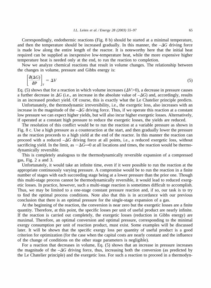
It is seen from Fig. 16, that there are optimal operating pressures corresponding to the minimalspecific exergy expenditures (Eq. (22)). The value of the optimal pressure depends on theH2O:CH4 ratio, i.e., steam/gas ratio. These results are close to commercial operating conditions.Interestingly, Fig. 16 also shows that the optimal operating pressure increases as the steam:gasratio decreases.
This result is to be expected. The relative effect of the volume increase, due to Eq. (18), isdiluted (by unreacted reagents) when the feedstock deviates from the stoichiometric steam/gasratio of 1. Thus, to decrease the specific exergy expenditure (Eq. (22)), the optimal “counteracting”
78 I.L. Leites et al. / Energy 28 (2003) 55–97
Fig. 16. Effect of pressure on specific exergy expenditure in methane reforming.
operating pressure should increase as the steam/gas ratio approaches the stoichiometric ratio, andvice versa. This is precisely the effect shown in Fig. 16.
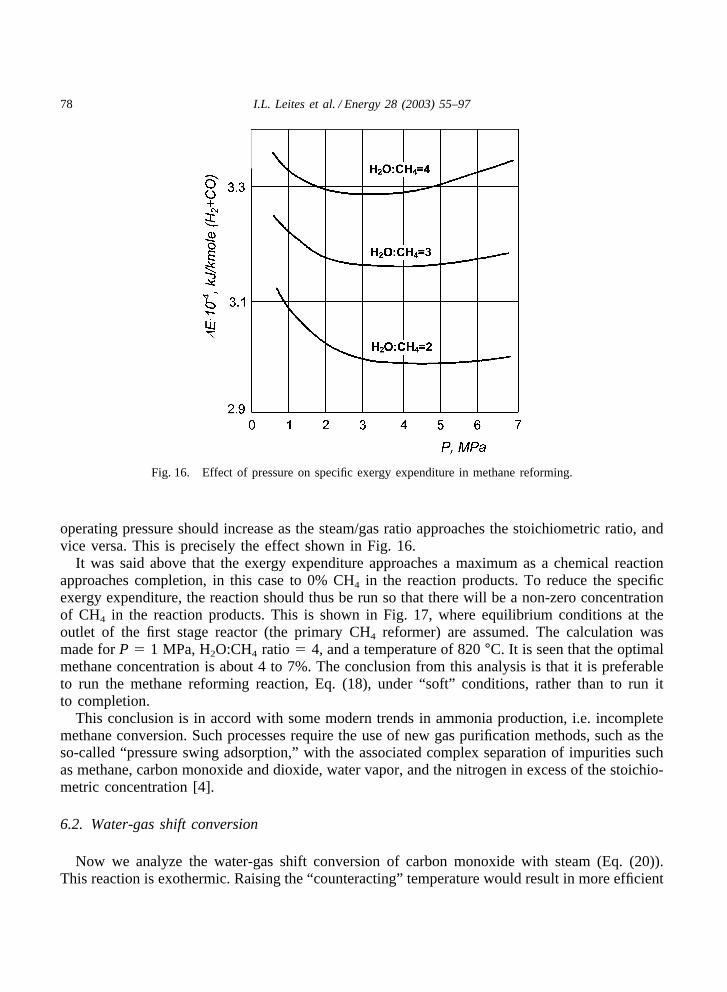
It was said above that the exergy expenditure approaches a maximum as a chemical reactionapproaches completion, in this case to 0% CH4 in the reaction products. To reduce the specificexergy expenditure, the reaction should thus be run so that there will be a non-zero concentrationof CH4 in the reaction products. This is shown in Fig. 17, where equilibrium conditions at theoutlet of the first stage reactor (the primary CH4 reformer) are assumed. The calculation wasmade for P � 1 MPa, H2O:CH4 ratio � 4, and a temperature of 820 °C. It is seen that the optimalmethane concentration is about 4 to 7%. The conclusion from this analysis is that it is preferableto run the methane reforming reaction, Eq. (18), under “soft” conditions, rather than to run itto completion.
This conclusion is in accord with some modern trends in ammonia production, i.e. incompletemethane conversion. Such processes require the use of new gas purification methods, such as theso-called “pressure swing adsorption,” with the associated complex separation of impurities suchas methane, carbon monoxide and dioxide, water vapor, and the nitrogen in excess of the stoichio-metric concentration [4].
6.2. Water-gas shift conversion
Now we analyze the water-gas shift conversion of carbon monoxide with steam (Eq. (20)).This reaction is exothermic. Raising the “counteracting” temperature would result in more efficient

79I.L. Leites et al. / Energy 28 (2003) 55–97
Fig. 17. Specific exergy expenditure per kmole of product H2+CO in reaction (20) as a function of concentration ofCH4 (YCH4) in reaction products.
use of the reaction heat, but would also decrease conversion. Again, an optimal temperature thusexists, corresponding to minimal specific exergy expenditures (Eq. (22)).
Note, that, since there is no volume change in the shift reaction (Eq. (20)), we do not expectpressure to be a significant process variable with respect to exergetic efficiency.
There are, however, two additional process variables that can affect the exergetic efficiency ofthe water gas shift process: the CO concentration at the outlet of the reactor, and the steam:gasratio, r, at the reactor inlet. Thus, in addition to an optimal temperature, we can also expect thatthere is an optimal outlet CO concentration as well as an optimal inlet steam:gas ratio.
Fig. 18 shows the effect of temperature on specific exergy expenditure for a series of outletCO percentages. This figure, based on calculations assuming that the reactor outlet is at thermo-dynamic equilibrium, shows that the optimal temperature is lower than 400 °C. This is close tothe actual temperature at the first stage of commercial shift processes.
In Fig. 18, each point on a constant % CO curve represents a different inlet steam:gas ratio.The effects of steam:gas ratio and outlet % CO are shown in Fig. 19 (where each point on acurve represents a different temperature). The optimal conditions are a steam:gas ratio of 0.35and an exit CO concentration near 5%.
It was stated above, that an excess of one of the reagents results in increased exergy expenditure,but it increases conversion. It is seen from Fig. 20 (where each point on a curve represents adifferent exit CO concentration), that there is an optimal steam:gas ratio where the specific exergy

80 I.L. Leites et al. / Energy 28 (2003) 55–97
Fig. 18. Dependence of specific exergy expenditure in reaction (20) on temperature at the outlet of the reactor atdifferent CO concentration in reaction product.
Fig. 19. Specific exergy expenditure per m3 H2 produced by reaction (20) as a function of YCO concentration ofreacted CO in reaction products, at different steam:gas ratios (numbers on lines).

81I.L. Leites et al. / Energy 28 (2003) 55–97
Fig. 20. Dependence of specific exergy expenditure per m3 H2 produced by reaction (20) on the ratio (r) steam:gasat different temperatures.
Fig. 21. Two stage CO conversion by steam (reaction 20). 1—high temperature conversion; 2, 3—utilization of heatof converted gas; 4—low temperature conversion.
expenditures are minimal. This value is near 0.25 at 300–400 °C, and is lower than generallyused in practice.
Some conclusions can be drawn from these calculations about the possibility of furtherreduction of energy resource usage. The first conclusion is to use a conventional two-stage COshift reactor, with a high temperature in the first stage and a reduced temperature in the secondstage (Fig. 21). The high-temperature heat of reaction from the first stage is used to producesteam, or is recovered for other purposes, while increased conversion is achieved as a result ofthe lower temperature in the second stage.
However, the best design can be developed on the basis of the Linde idea of the use of a heat

82 I.L. Leites et al. / Energy 28 (2003) 55–97
exchanger combined with the reactor (see Fig. 22) to integrate the reaction with the extractionof its heat of reaction. This allows a gradual decrease in the temperature of the working mediumfrom the start to the end of the reactor. In this way it is possible to use the reaction heat withmaximal efficiency within the reactor and to run the reaction to completion, as was previouslysuggested in Fig. 8.
6.3. Ammonia synthesis
One other commercial example of use of the reaction heat is the three-stage ammonia synthesis(see Fig. 23). In this example the exothermic synthesis, Eq. (21), is run at three different graduallyreduced temperatures, while the high temperature reaction heat from the first stage is used to
Fig. 22. Linde isothermal reactor of CO conversion by steam with removal of reaction heat from the reactor.
83I.L. Leites et al. / Energy 28 (2003) 55–97
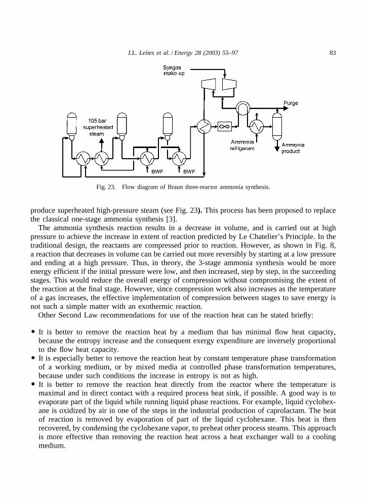
Fig. 23. Flow diagram of Braun three-reactor ammonia synthesis.
produce superheated high-pressure steam (see Fig. 23). This process has been proposed to replacethe classical one-stage ammonia synthesis [3].
The ammonia synthesis reaction results in a decrease in volume, and is carried out at highpressure to achieve the increase in extent of reaction predicted by Le Chatelier’s Principle. In thetraditional design, the reactants are compressed prior to reaction. However, as shown in Fig. 8,a reaction that decreases in volume can be carried out more reversibly by starting at a low pressureand ending at a high pressure. Thus, in theory, the 3-stage ammonia synthesis would be moreenergy efficient if the initial pressure were low, and then increased, step by step, in the succeedingstages. This would reduce the overall energy of compression without compromising the extent ofthe reaction at the final stage. However, since compression work also increases as the temperatureof a gas increases, the effective implementation of compression between stages to save energy isnot such a simple matter with an exothermic reaction.
Other Second Law recommendations for use of the reaction heat can be stated briefly:
� It is better to remove the reaction heat by a medium that has minimal flow heat capacity,because the entropy increase and the consequent exergy expenditure are inversely proportionalto the flow heat capacity.
� It is especially better to remove the reaction heat by constant temperature phase transformationof a working medium, or by mixed media at controlled phase transformation temperatures,because under such conditions the increase in entropy is not as high.
� It is better to remove the reaction heat directly from the reactor where the temperature ismaximal and in direct contact with a required process heat sink, if possible. A good way is toevaporate part of the liquid while running liquid phase reactions. For example, liquid cyclohex-ane is oxidized by air in one of the steps in the industrial production of caprolactam. The heatof reaction is removed by evaporation of part of the liquid cyclohexane. This heat is thenrecovered, by condensing the cyclohexane vapor, to preheat other process steams. This approachis more effective than removing the reaction heat across a heat exchanger wall to a coolingmedium.

84 I.L. Leites et al. / Energy 28 (2003) 55–97
7. Some examples of use of the analysis based on the “driving force method”
7.1. Methane reforming
The conventional steam/methane reforming process is shown in Fig. 27a. The primary reaction(Eq. (18)) is endothermic, and the required heat is supplied by the combustion of methane by air.
Changes in methane concentration along the primary reactor are shown in Fig. 24. It is seenthat the CH4 concentration (line 2) decreases continuously along the tube, nearly approaching theequilibrium concentration at the end. It is also seen that the equilibrium concentrations (line1), corresponding to the real temperatures in tubes, are substantially lower than the operatingconcentrations except at the reactor outlet. This picture allows us to conclude that it is desirableto reduce the temperature at the start of the process by reducing the quantity of combusted gasin the inter-tube area. The extent to which the temperature can be reduced is seen from Fig. 25,where the real (line 2) and equilibrium (line 1) temperatures of this process are shown.
Different methods of reducing the driving force during steam methane reforming in tubularreactors are used in commercial practice, although the authors believe that good engineering canbe applied to develop other methods. One of the realized versions is demonstrated in Fig. 26 [5].It is a so-called Pre-Reformer. Briefly, the mixed raw materials, i.e. methane and steam are pre-heated, and the first stage of reaction is realized adiabatically without combustion of natural gasfor heating. It is seen that the temperature in the early stage of reforming is lower than that inconventional primary reforming. This partial modernization of the classical process has reducedthe consumption of natural gas for combustion by 5–10%.
Fig. 24. The concentrations of methane in tube steam methane converter along tubes1—the equilibrium line; 2—theoperating line.

85I.L. Leites et al. / Energy 28 (2003) 55–97
Fig. 25. The temperatures in tube steam methane reformer along tubes1—the equilibrium line; 2—the operating line.
Significantly better results have been obtained by development in Russia of the so-called “Tan-dem” process (Fig. 27 b), or autothermal reforming [4], and similar versions. The previous exergyanalysis of the conventional process [24] of the steam catalytic conversion of methane in tubularreactors showed that the main exergy losses are the result of the thermodynamic irreversibilityof methane combustion, and of the high difference between the burning gas temperature and thetemperature inside the tube. There are also large losses in the utilization of the heat in the fluegas leaving the main part of the tubular furnace.
The new Tandem process (Fig. 27 b) has reduced losses. The secondary reformer operates ata higher temperature since the residual methane is oxidized with enriched air. The heat from thesecondary reformer is at a high enough temperature to be used directly in the primary reformer.Thus there is no need to produce steam with its associated exergy loss, to recover heat from thesecondary reformer, as is done in the conventional process (Fig.14, unit 3).
A heat balance analysis of the flow sheet for the Tandem process (Fig. 27 b) shows that ordi-narily it is impossible to completely supply the primary endothermic reformer 1 with heat fromthe exothermic secondary reformer 2. Thus, non-conventional design decisions must be employedparticularly for synthesis gas produced for ammonia synthesis, which requires a stoichiometric(H2+CO):N2 ratio of 3:1. The Tandem process, used commercially for more than a dozen years,uses two non-conventional design decisions:
1. The CH4 concentration from the primary converter is increased, and a small quantity of O2 isadded to air in the secondary converter.
2. When used to produce synthesis gas for the synthesis of ammonia, it is necessary to use cryo-genic, or pressure swing adsorption (PSA), to achieve the required (H2+CO):N2 ratio of 3:1,or to remove excess CH4.

86 I.L. Leites et al. / Energy 28 (2003) 55–97
Fig. 26. Steam reforming of methane with combustion of natural gas in furnace and with(a) Pre-Reforming; (b) Basicconcept of Pre-Reformer [5].
By the way, this process is an excellent example of the combination of reduced energy resourcesconsumption, lower capital costs, and less contamination of the environment. Many calculationshave shown that the major capital costs are in primary reforming. The tubes in the new TandemProcess operate with a low pressure difference across the tube wall compared with the classical

87I.L. Leites et al. / Energy 28 (2003) 55–97
Fig. 27. The networks of steam methane reforming for ammonia production:(a) The conventional process; 1—theprimary reforming with combustion of natural gas, 2—the secondary reforming(b) The Tandem process; 1—the primaryreforming, 2—the secondary reforming.
version (Fig. 27a), and their cost is low. This new process uses much less fuel and, as a result,operates with reduced contamination of the environment by nitrogen oxides, carbon dioxide, andso on.
7.2. Removal of CO2 from synthesis gas
The driving force method has been used with success to reduce heat consumption in the removalof carbon dioxide from synthesis gas by absorption with aqueous monoethanolamine (MEA) sol-ution [25,26,32,33,37].
The flow sheet of the conventional version of the CO2 removal process is shown in Fig. 15.CO2 is removed from the synthesis gas by solutions of MEA in water. The gas mixture to bepurified enters the bottom of absorber I. The MEA is regenerated by using heat in regenerator IIto strip the CO2 out. The cooled regenerated MEA solution enters the top of the absorber. Thesaturated MEA absorbent removed from the absorber bottom is preheated in heat exchanger IIIby the regenerated MEA absorbent leaving the bottom of desorber II.
Analysis of the equilibrium and operating lines of a chemidesorption unit (see Fig. 12) showsthat equilibrium can be reached at only one point of a chemidesorber of conventional design (witha single feed of spent absorbent entering the top, Fig. 15), even if it were of infinite height. Thus,the driving force at other points in the desorber can never approach zero, resulting in excessiveexpenditure of exergy.

88 I.L. Leites et al. / Energy 28 (2003) 55–97
The same is especially true for CO2 absorption by MEA (Fig. 13), where the great irreversibility(excessive driving force) is in the middle and bottom parts of the column.
These conclusions as well as the results of quasi-static analysis generated the ideas that led tothe revision of the flow sheets for MEA gas purification, which were incorporated in many largeammonia plants in Russia. The first version (Fig. 28) is the flow sheet [33,37] with three streamsof rich solution entering regenerator II, and the use of two streams of regenerated absorbententering absorber I. The equilibrium and operating lines of such a multiflow desorption processare shown in Fig. 29.
A second revised flow sheet fully integrates the stripping process and heat transfer (Fig. 30)At first glance the designs shown in Figs. 28 and 30 are different. But the main idea is the
same, i.e., to approach the theoretical limit of adding and removing all streams of energy andsubstances along the entire height of the columns.
The commercial result of this analysis was that the heat consumption at more than 20 newplants (without substitution of absorbent) was reduced to 1/2 or 1/3 of the heat used in the conven-tional process.
Calculations show that similar designs can be used for the modification of MDEA(methyldiethanolamine) gas purification plants, which would then operate with as little as onehalf the heat consumption of the best commercial plants.
It seems that these examples confirm the fruitfulness of this analysis for the reduction ofenergy consumption.
Similar deductions can be made from the quasi-static analysis (see below).
Fig. 28. Process flow diagram for purification of gas from CO2 with MEA solution in 1500 MTPD ammonia plantwith three flows of saturated solution and two flows of regenerated solutions [33].I —absorber, II—regenerator, III—heat exchanger, IV—cooler, V—cooler (condenser) for steam-gas mixture, VI—reboiler, VII—pumps

89I.L. Leites et al. / Energy 28 (2003) 55–97
Fig. 29. The equilibrium (1) and operating (2) lines of multiflow CO2 desorption from MEA solution (one version).
Fig. 30. Process flow diagram for purification of gas from CO2 with MEA solution in 1500 MTPD ammonia plantwith integration of solution regeneration and heat recuperation [37].I—absorber, II—regenerator, III—heat exchanger,IV—cooler of solution, V—cooler (condenser) for steam-gas mixture, VI—reboiler, VII—pumps
8. Some examples of use of the quasi-static method
The analysis of the theoretical quasi-static version of industrial processes [32,38] can give veryimportant guidance for:
� calculating the best, i.e. limiting energy characteristics of a process;

90 I.L. Leites et al. / Energy 28 (2003) 55–97
� determining the technological conditions of such a process;� understanding which methods can be used to improve the commercial process;� calculating the optimal operating conditions for a given processes flow sheet.
8.1. Chemisorption of CO2
To start, let us analyze a typical example of a countercurrent heterogeneous exothermic reaction:chemisorption of CO2 by an aqueous MEA solution in a conventional absorber with a standardflow sheet (Fig. 15). When operated without heat removal or supply to the absorber, the tempera-ture of the absorbent (see Fig. 31, line 1) increases from the top to the bottom of the absorberdue to the heat of reaction. However, if we could run the absorption (see Fig. 31, line 2) alongthe equilibrium line, that is, in a quasi-static way with zero driving force, the temperature changeis just the opposite. The temperature of the quasi-static process is considerably higher than thereal temperature and must decrease, not increase, from the top to the bottom of the absorber. Thisinsight led to a revised flow sheet for CO2 removal by MEA, with high temperature absorptionat the top part of the absorber, removal of hot absorbent from the middle part of the column,recovery of part of the heat of absorption, and then reinjection of the absorbent at a lower tempera-ture into the absorber.
8.2. Desorption of CO2
Additional unexpected and fruitful results were obtained from the quasi-static analysis of thedesorption of CO2 and H2S from various chemisorbents such as MEA, DEA (diethanolamine),
Fig. 31. Change in temperature of absorbent during CO2 absorption by MEA solution from the top to the bottom ofabsorber as a function of absorbent saturation.1—the real process, 2—the quasi-static process.
91I.L. Leites et al. / Energy 28 (2003) 55–97
nonaqueous MEA solutions and so on. The method of calculation and the results, with detailedmathematical analysis, are described in the author’s papers and book [32,33,38].
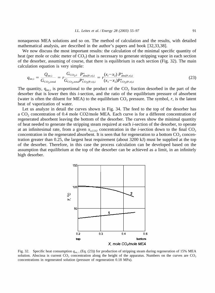
We now discuss the most important results: the calculation of the minimal specific quantity ofheat (per mole or cubic meter of CO2) that is necessary to generate stripping vapor in each sectionof the desorber, assuming of course, that there is equilibrium in each section (Fig. 32). The maincalculation equation is very simple:
qstr,i �Qstr,i
GCO2,total
� rGCO2,i
GCO2,total
P∗abs(P,x),i
P∗CO2(P,x),i
� r(xi�x2)(x1�x2)
P∗abs(P,x),i
P∗CO2(P,x),i
(23)
The quantity, qstr,i is proportional to the product of the CO2 fraction desorbed in the part of thedesorber that is lower then this i-section, and the ratio of the equilibrium pressure of absorbent(water is often the diluent for MEA) to the equilibrium CO2 pressure. The symbol, r, is the latentheat of vaporization of water.
Let us analyze in detail the curves shown in Fig. 34. The feed to the top of the desorber hasa CO2 concentration of 0.4 mole CO2/mole MEA. Each curve is for a different concentration ofregenerated absorbent leaving the bottom of the desorber. The curves show the minimal quantityof heat needed to generate the stripping steam required at each i-section of the desorber, to operateat an infinitesimal rate, from a given xi,CO2 concentration in the i-section down to the final CO2
concentration in the regenerated absorbent. It is seen that for regeneration to a bottom CO2 concen-tration greater than 0.25, the largest heat requirement (about 3200 kJ) must be supplied at the topof the desorber. Therefore, in this case the process calculation can be developed based on theassumption that equilibrium at the top of the desorber can be achieved as a limit, in an infinitelyhigh desorber.
Fig. 32. Specific heat consumption qstr, i (Eq. (23)) for production of stripping steam during regeneration of 15% MEAsolution. Abscissa is current CO2 concentration along the height of the apparatus. Numbers on the curves are CO2
concentrations in regenerated solution (pressure of regeneration 0.18 MPa).

92 I.L. Leites et al. / Energy 28 (2003) 55–97
However, as is seen from Fig. 34, the attempt to further reduce the bottom CO2 concentration,results in a striking increase in the minimum heat requirement: to 16,000 kJ for a bottom CO2
concentration of 0.05 mole CO2/ mole MEA.It is to be expected that the amount of stripping vapor increases as the bottom CO2 concentration
decreases: approaching infinity as the bottom CO2 concentration approaches zero. However, thenature of the curves in Fig. 34 reflect the peculiarity of the vapor-liquid equilibrium for aqueousMEA solutions, whose equilibrium partial pressure, P∗
CO2, decreases rapidly.This analysis allowed, as a result (see the details in [33]), calculation of the optimal conditions
for MEA regeneration, and a reduction in the heat consumption at operating commercial units.Also, this analysis led to new ideas for changes in the flow sheet that were additional to thoseobtained from the previous driving-force analysis.
The dependence of the minimal reflux ratio, PH2O/PCO2, on the CO2 concentration in a regener-ated aqueous MEA absorbent was calculated, and is shown in Fig. 33. The minimum reflux ratiois constant for high CO2 concentration in the lean solution, but increases rapidly for CO2 concen-trations below about 0.17. Correspondingly, the minimal heating requirements to regenerate leansolution would also increase rapidly as the CO2 concentration decreased below this level. It isimportant to point out that these results were obtained for a desorber where thermodynamic equi-librium is achieved (one with infinite height and ideal mass transfer rates). Thus, these resultsare reflections of the inherent thermodynamic properties of the CO2/aqueous MEA system, andare not characteristics of an actual desorption apparatus (number and efficiency of plates, orvolume and efficiency of packing). These results, originally published in Russian in 1968 [32]
Fig. 33. The dependence of reflux ratio f on the x concentrations of CO2 in regenerated aqueous 15% MEA solutionunder pressure 0.18 MPa at quasi-static stripping.

93I.L. Leites et al. / Energy 28 (2003) 55–97
Fig. 34. Dependence of the minimal heat consumption q for MEA purification of gas from CO2 on the x-concentrationof the CO2 in regenerated solution at Pstr=0.18 MPa, t=15 °C. The CO2 concentration in the rich absorbent is 0.4 moleCO2/mole MEA.1—�H —heat of absorption; 2—qstr under equilibrium conditions at the top of stripper; 3—heat forheating of absorbent; 4—1+3; 5—1+2+3—complete heat consumption; 6—q in “critical section” ; 7—complete heatconsumption if it is limited by equilibrium in the “critical section” .
explain why it is difficult to regenerate MEA solutions to very low CO2 concentrations. The sameanalysis was also applied to other similar processes that desorb H2S and CO2 from various absorb-ents. The results of the calculation confirming the existence of the optimal desorption conditionscorresponding to the minimal specific heat consumption are shown at Fig. 34. A more detailedexplanation of the reasons for this minimum is given below.
It is known that for the simple flow sheet (Fig. 15) the heat consumption can be calculatedapproximately as follows:
Q � GCO2�H � Lc�th � GCO2
rPH2O
PCO2
(24)
wherePH2O
PCO2
� �Then, because GCO2=L·�x, �x=x1-x2, the specific heat consumption (per 1 m3
of CO2):
q � �H �c�th
�x� r� (25)
The first part of Eqs. (24) and (25) is the thermodynamic heat for gas desorption (approximatelyequal to its heat of absorption). The second part is for heating the liquid absorbent further, follow-ing the recovery of available process heat. The lower the CO2 concentration, x2, in the leansolution, the larger is the absorptivity of the absorbent, �X, and the lower is the specific heatrequired to heat the absorbent (Eq. (25)). But, the third part of Eqs. (24) and (25) is the heat ofdesorption of water from the critical section of the desorber, which, as is seen from Fig. 34 (line6), increases when the CO2 concentration in the lean solution is reduced. This is the physical

94 I.L. Leites et al. / Energy 28 (2003) 55–97
background, leading to the existence of a thermodynamically based optimal gas concentration inthe lean solution, that results in a minimal heat consumption for the conventional flow sheet(Fig. 15)
This result was confirmed many times at operating plants, and, by stripping only down to theoptimal CO2 concentration, led to a reduction in heat consumption.
However, when fine gas purification is needed, it may be necessary to strip to a lower thanoptimal CO2 concentration. Using the conventional flow sheet (Fig. 15), this would require anincrease in heat consumption. However, this increase in heat consumption can be avoided byrevising the flow sheet to use two streams of lean absorbent, each of different CO2 concentration(Figs. 28 and 30). This allows an increase in the absorptivity of the solution and achieves thefine gas purification without increasing the reflux ratio.
It seems that this method of analysis can be used more extensively than it is used now.
9. Conclusions
We have shown here that appropriate use of Second Law concepts can help one understandhow to reduce energy consumption in the chemical industry
The main concepts used in this paper are generalized in the chart of Fig. 35. It is seen that the
Fig. 35. Some consequences of the Second Law and methods of analysis based on them.
95I.L. Leites et al. / Energy 28 (2003) 55–97
“driving force analysis” and the “quasi-static analysis” are consequences of the Second Law, butare not connected with exergy analysis.
The “counteraction principle” , also a consequence of the Second Law, was used with exergyanalysis and Le Chatelier’s principle, to optimize energy usage. At the exergetic optimum for agiven flow sheet, the optimum extent of reaction, excess reagent concentrations, temperature, andpressure, are fixed. However, after finding these optimum conditions, the designer should not becomplacent but, rather, should try to create a new flow sheet that further reduces excessive drivingforces, to arrive at an improved exergetic optimum.
Finally, a summary of the definitions of the methods proposed here are given below:
9.1. The “Counteraction principle”
The counteraction principle is the Second Law requirement that: to make maximal use of theGibbs energy of chemical reactions and similar processes, i.e., to minimize exergy expenditures,it is necessary to retard the reactions, i.e., to conduct them under conditions that are COUNTERto the conditions favorable to increasing the species conversion.
9.2. The “Driving force method”
The driving force method consists of the analysis of driving forces of a process at all pointsin a chemical process apparatus, and the development of the engineering methods to changeprocess conditions and flow sheets in order to reduce the driving force and, consequently, toreduce thermodynamic irreversibility.
9.3. The “Quasi-static method
The quasi-static method consists of the examination of the process conditions of a theoreticallimiting quasi-static process that could be run with zero driving force along the equilibrium line,followed by comparison of such a fictitious but conceivable process with a real one, to discoverengineering techniques that allow a real process to approach this quasi-static one.
Brief recommendations that are reflections of this paper, and were published in similar formpreviously [27], are listed below.
10. 12 Second Law of Thermodynamics commandments for reducing energy consumption
1. The driving force of a process must approach zero at all points in a reactor, at all times. Tryto change the driving force to a uniform one.
2. Wherever possible, retard a process at the start, then gradually remove the retarding function.3. If the reaction is exothermic it is necessary to raise (not to lower!) the temperature. If the
reaction is endothermic, it is necessary to lower (not to raise!) the temperature. It is better toconduct the exothermic processes in a low flow-heat-capacity medium. It is better to removereaction heat by phase change of the cooling medium, or by endothermic reactions, rather thanby sensible heating of a cooling medium.

96 I.L. Leites et al. / Energy 28 (2003) 55–97
4. If the reaction is conducted in the gas phase and the volume increases, it is necessary to raise(not to reduce!) the pressure. If the gas volume decreases, it is necessary to reduce (not toincrease!) the pressure4.
5. It is not necessary to carry out chemical reactions up to their completion. It is better to recyclethe unreacted streams.
6. Do not mix streams of different temperatures, different compositions, or different pressures. Ifpossible, don’ t mix anything!
7. Remember that the increase in the process rate often leads to an increase in energy resource con-sumption.
8. Select the lowest temperature heat sources.9. The best chemical reactor is a counter-current one with plug flow.10. Investigate the conditions of quasi-static processes to discover methods for reducing energy
resource consumption.11. The best process is the one in which energy and species enter and leave along the full length
of the apparatus.12. A chemical process cannot be thermodynamically reversible if it has a stoichiometric excess;
however, real processes can operate with minimal exergy expenditures at optimal stoichiometricexcesses that are functions of the flow sheet.
References
[1] Haywood RW. Equilibrium thermodynamics for engineers and students. Chichester, New York, Brisbane, Toronto:Wiley Interscience Publication, John Wiley and Sons Inc., 1981.
[2] Jung M. Revamping: breathing new life into old ammonia plants. Nitrogen 1991;191(May–June):42–52.[3] Grotz BJ, Grisolia L. Fifth anniversary of ammonia unit E. Nitrogen 1992;September-October:39–45.[4] Apple M. Modern ammonia technology. Nitrogen 1992;199(September-October):46.[5] Cromarty BJ, Crewanden BJ. Pre-reforming cases reduce reforming furnace firing requirements. Nitrogen
1991;May-June:30–4.[6] Anon. A combination of proven technologies. Nitrogen 1994;208:44–9.[7] Gilmont R. Thermodynamic principles for chemical engineers. Englewood Cliffs N.J: Prentice-Hall, Inc, 1959.[8] Denbigh KG. The principles of chemical equilibrium with applications in chemistry and chemical engineering.
Cambridge: Cambridge University Press, 1955.[9] Obert EF. Concepts of thermodynamics. New York, Toronto, London: McGraw Hill Book Company Inc., 1960.
[10] Ahern JE. The exergy method of energy system analysis. New York, Chichester, Brisbane, Toronto: John Wileyand Sons Inc., 1980.
[11] Fratzcher W, Brodyansky V, Michalek K. Exergy, Theorie und anwendung. Leipzig: VEB Deutcher Verlag furGrundstoff Industrie, 1986 in German.
[12] Brodyansky V, Sorin M, Le Goff P. The efficiency of industrial processes, Exergy analysis and optimization.Amsterdam: Elsevier, 1994.
[13] Gaggioli R, Petit J. Use the Second Law, first. Chemtech 1977;August:496–506.[14] Szargut J. International progress in Second Law analysis. Energy 1980;5:709–18.[15] Townsend DS. Second Law analysis in practice. Chem Eng 1980;October:628–33.[16] Kestin J. Availability: the concepts and associated terminology. Energy 1980;5:679–92.
4 At first glance, Commandments 3 and 4 appear to contradict Le Chatelier’s principle but they are based on the Second Law andfollow from Le Chatelier’s principle, which is also a consequence of the Second Law.

97I.L. Leites et al. / Energy 28 (2003) 55–97
[17] de Nevers N. The second way to use the Second Law. Chemtech 1982;May:308–17.[18] Linnhoff B. New concepts in thermodynamics for better chemical process design. Chem Eng Res Des
1983;61(July):207–22.[19] Sama DA, Qian S, Gaggioli R. A common-sense Second Law approach for improving process efficiencies. In:
Proc of the International Symposium on Thermodynamic Analysis and Improvement of Energy Systems, Beijing,China: June 5-8, 1989: 520-531, Beijing: International Academic Publishers (Pergamon Press).
[20] Sama DA. The use of the Second Law of thermodynamics in the design of heat exchangers, networks, andprocesses. In: Proc of the International Conference on Energy Systems and Ecology, ENSEC’93, Poland, July 5-9; 1993: 1–24, Polish Ministry of National Education, Warsaw, Poland.
[21] Kjelstrup S, Sauar E, Bedeaux D, van der Kooi H. The driving force distribution for minimum lost work inchemical reactors close to and far from equilibrium. 1. Theory. Ind Eng Chem Res 1999;38:3046–50.
[22] Kjelstrup S, Island TV. The driving force distribution for minimum lost work in chemical reactors close to andfar from equilibrium. 2. Oxidation of SO2. Ind Eng Chem Res 1999;38:3051–5.
[23] Johanessen E, Nummedal L, Kjelstrup S. Minimizing the entropy production in heat exchange. Int J Heat MassTransfer 2002;45:2649–54.
[24] Leites IL, Sosna MH, Semenov VP. The theory and the practice of the chemical energy technology. Moscow:Chimia, 1988 [in Russian].
[25] Leites IL, Berchenko VM. The application of the Second Law of thermodynamics for optimization of absorptionprocesses to decrease the energy consumption. In: Proc. International Conf. ENSEC’93, Energy Systems andEcology: Poland, July 5-9, 1993: 771-778. Polish Ministry of National Education, Warsaw, Poland.
[26] Leites IL, Berchenko VM. The exergetical optimization of the chemical reaction conditions. In: Proc. ECOS’95,Istanbul, Turkey: 157-159. Mechanical Engineering Department, Middle East Technical University, TR-06531,Ankara, Turkey.
[27] Leites IL. 12 commandments of the Second Law of thermodynamics for energy saving. Addendum to Proc.ECOS’95, Istanbul, Turkey, v.3: 41 Mechanical Engineering Department, Middle East Technical University, TR-06531, Ankara, Turkey.
[28] Leites IL. Calculation of exergy of nonideal systems and principle of counteraction for energy saving. Proc.ECOS’96, Stockholm, Sweden, June 25-27, 1996: 25-28. Department of Chemical Engineering and Technology,Division of Energy Processes, Royal Institute of Technology, S-100 44 Stockholm, Sweden.
[29] Petliuk FB, Platonov VM. Thermodynamically reversible multicomponent rectification. Chim Prom(Chimicheskaya Promishlennost) 1964;10:723–5 [in Russian].
[30] Platonov VM, Petlyuk FB. The efective method of rectification of multicomponent mixtures. Chim Prom(Chimicheskaya Promishlennost) 1982;8:488–92 [in Russian].
[31] Daniels F, Alberty R. Physical chemistry., 2nd ed New York, London: John Wiley and Sons, 1961.[32] Leites IL, Brandt BB, Sichkova OP. The optimal regeneration conditions of monoethanolamine solution at gas
purification from carbon dioxide. Chim Prom (Chimicheskaya Promishlennost) 1968;9:682–6 [in Russian].[33] Semenova TA, Leites IL, editors. The purification of technological gases. Moscow: Chimia; 1977. [in Russian].[34] Dunbar WR, Lior N, Gaggioli R. The component equations of energy and exergy. ASME JEnergy Res Tech
1992;114:75–83.[35] Dunbar WR, Lior N. Sources of combustion irreversibility. Comb Sci Technol 1994;103:41–61.[36] Gohshtein D. Entropy method of calculation of energy losses., 2nd ed Moscow-Leningrad: Gosenergoisdat, 1963
[in Russian].[37] The Handbook of the nitrogen engineer, Moscow: Chimia, 1986 [in Russian].[38] Leites IL. The Thermodynamics of CO2 solubility in mixtures monoethanolamine with organic solvents and water
and commercial experience of energy saving gas purification technology. Energy Convers Mgmt 1998;39(16–18):1665–74.
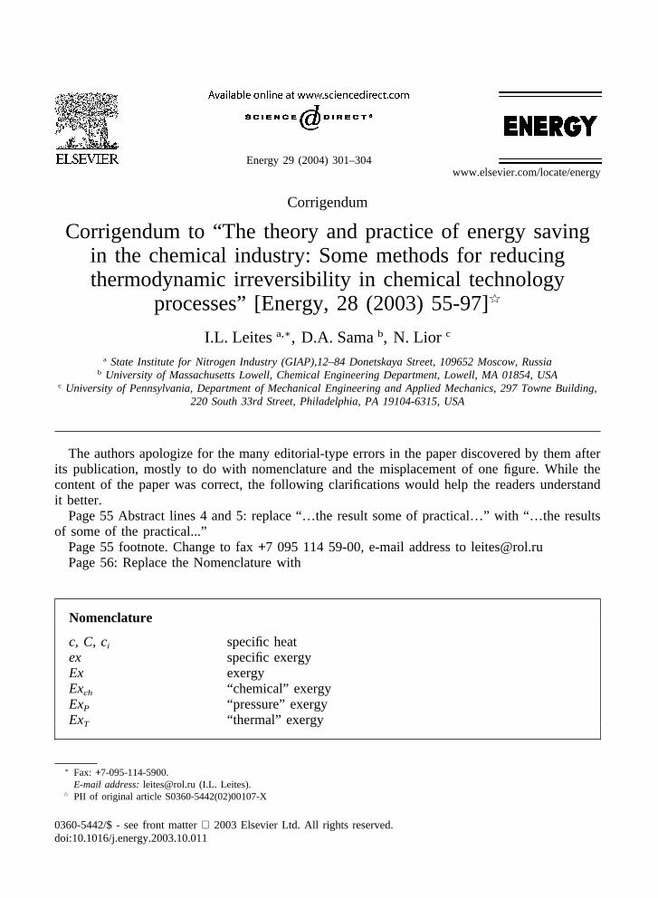
Energy 29 (2004) 301–304www.elsevier.com/locate/energy
Corrigendum
Corrigendum to “The theory and practice of energy savingin the chemical industry: Some methods for reducingthermodynamic irreversibility in chemical technology
processes” [Energy, 28 (2003) 55-97]�
I.L. Leitesa,∗, D.A. Samab, N. Lior c
a State Institute for Nitrogen Industry (GIAP),12–84 Donetskaya Street, 109652 Moscow, Russiab University of Massachusetts Lowell, Chemical Engineering Department, Lowell, MA 01854, USA
c University of Pennsylvania, Department of Mechanical Engineering and Applied Mechanics, 297 Towne Building,220 South 33rd Street, Philadelphia, PA 19104-6315, USA
The authors apologize for the many editorial-type errors in the paper discovered by them afterits publication, mostly to do with nomenclature and the misplacement of one figure. While thecontent of the paper was correct, the following clarifications would help the readers understandit better.
Page 55 Abstract lines 4 and 5: replace “…the result some of practical…” with “…the resultsof some of the practical...”
Page 55 footnote. Change to fax+7 095 114 59-00, e-mail address to [email protected] 56: Replace the Nomenclature with
Nomenclature
c, C, ci specific heatex specific exergyEx exergyExch “chemical” exergyExP “pressure” exergyExT “thermal” exergy
∗ Fax: +7-095-114-5900.E-mail address: [email protected] (I.L. Leites).
� PII of original article S0360-5442(02)00107-X
0360-5442/$ - see front matter 2003 Elsevier Ltd. All rights reserved.doi:10.1016/j.energy.2003.10.011

302 Corrigendum / Energy 29 (2004) 301–304
Fh area of heat transfer or mass transferg acceleration of gravityG Gibbs energy, or molar or volume flow rateGi = mi partial molal Gibbs energy, chemical potential of i-componenth number of moles of species C, Eq. (1)H enthalpyHi partial molal enthalpy�H change in enthalpyj number of moles of species D, Eq. (1)Ke chemical equilibrium constantKh, Km heat transfer rate coefficient, mass transfer rate coefficientn quantity of moles; number of moles of species A, Eq. (1)L quantity of liquidm number of moles of species B in Eq. (1); mass in Eq. (8a)P pressurePGAS current gas pressureP∗
abs(P,x),i equilibrium absorbent vapor pressure (here water); underconditions in stripper corresponding to the boiling temperatureunder P and at x – CO2 concentration in absorbent in stripperin i-section
PCO2(P,x),i equilibrium CO2 pressure corresponding to the boilingtemperature under P in stripper and x – CO2 concentration ini-section
PS pressure of the surroundingsP∗
i partial equilibrium pressureq the minimal specific heat consumption for CO2 stripping (str)
in i-section (i) attributed to 1 cubic meter of total quantity ofCO2 desorbed in all stripper (GCO2, total)
Q quantity of substance mole/hour, kg/hour or m3/hour; in Eq.(4) – amount of heat
QPR quantity of useful reaction products, Eq. (22)Qstr,i the minimal total heat consumption for CO2 striping in
regenerator (stripper, desorber)r the specific heat of vaporization of water (or other stripping
agent)R universal gas constantS,Si entropy, partial molal entropyT, t temperatureT0 ambient temperatureU internal energyV, v volume, specific volumeW useful work

303Corrigendum / Energy 29 (2004) 301–304
Xi, xi concentration of species i, CO2 concentration in liquid in isection of desorber
x1, x2 correspondingly CO2 concentration in liquid in the top ofdesorber (1) and in the bottom (2)
yi, Yi concentration of species iYCO2 CO2 concentration in gas mixturez height
Greek
� Subtraction operator, e.g. �ExP = ExP2 - ExP1, change in“pressure” exergy, where subscript 1 is the initial state of thesystem and 2 a later state of the system
�exs specific exergy expenditure, Eq. (22)�Th = T6 – T1 in Fig. (15)
�Tt =(T4�T1)�(T2�T3)
1nT4�T1
T2�T3 Log mean temperature difference�W amount of work obtained during a chemical reaction� reflux ratio for strippingh, he second law (exergy) efficiency
ν =G2c2
G1C1
on page 69; velocity on page 71
Subscripts and abbreviations
bot bottomch chemicalcr (“critical” ) – the section of desorber (stripper) where the
driving force of desorption is minimalr,R, rev reversibleIr, IR irreversiblei, j species, or current states of a system, or a stream indexopt optimalp, prod productsP pressurer, react reactantsstr strippingt in Fig. 12 – top0 ambient parameter

304 Corrigendum / Energy 29 (2004) 301–304
Page 58 Fig. 1: species a, b, c, d in the figure should be denoted as A, B, C, D for consistencywith Eqs (1) and (2)
Page 66 line 17 from top: add the word “but” before “ they”Page 71 line one: replace: “…To,Po,vo = O, zo = O,…” with: “…To, Po, and where vo = 0, zo
= 0…”Page 73: in Eq. (15) replace To with To
Page 76. Add to caption of Fig. 14: in “ reaction N” , the number N always refers to the Eq.number in the text.
Page 78, 10th line under Fig. 16: replace “…under “soft” conditions, rather than to run it tocompletion” , with “… at lower steam/gas ratios, and to stop it short of completion.”
Page 79, in caption of Fig. 17: change from “20” to “18” .Page 89, in caption of Fig. 29: change “1” to “2” , and “2” to “1” .Page 91, line 5 after Eq. (23): change from “34” to “32.”line 11 after Eq. (23): change from “3200” to “3800” .replace Fig. 32 with the figure below.Page 92, first and 6th line from top: replace “34” with “32” .Page 93, in caption to Fig. 34: replace � with �. In the first line of the caption, after “CO2”
add: “ for the flow sheet shown in Fig. 15” .
Fig. 32. Specific heat consumption qstr,i (Eq. (23)) for production of stripping steam during regeneration of 15% MEAsolution. Abscissa is current CO2 concentration along the height of apparatus. Numbers on the curves are CO2 concen-trations in regenerated solution (pressure of regeneration 0.18 MPa)