the touran electrical system audi ssp/ssp 307 vw touran... · manageable level, volkswagen favours...
TRANSCRIPT

The TouranElectrical system
Design and function
Self-study programme 307
Service.

2
NEW ImportantNote
This self-study programme explains the design
and function of new developments.
The contents will not be updated.
For the latest testing, setting and repair
instructions, please refer to the relevant
workshop literature.
The networking technology, used until now only in luxury class vehicles, will be a feature in com-pact vans, such as the Volkswagen Touran.
The control units installed in this system also manage tasks that were previously carried out by relays and switches. In order that these tasks can be fulfilled efficiently, the units have to exchange a great deal of information (data) between each other. Such a high rate of data transfer would only be possible with a large number of cables if standard means were used, such as wiring con-nections. To keep the number of wiring connections at a manageable level, Volkswagen favours the use of data bus connections on a wider scale.
This self-study programme is designed to help you better understand the networking concept of the Volkswagen Touran.
It covers the allocation of control units to the various data bus systems, the fitting locations of relay slots, fuses and control units. Furthermore, it describes the various functions of and changes to the diagnosis system.
S307_050
3
Contents
Introduction . . . . . . . . . . . . . . . . . . . . . . . . . . . . . . . . . . . . . . 4
LIN data bus . . . . . . . . . . . . . . . . . . . . . . . . . . . . . . . . . . . . 16
Onboard power supply . . . . . . . . . . . . . . . . . . . . . . . . . . . 20
Data bus diagnosis interface . . . . . . . . . . . . . . . . . . . . . . 24
Onboard power supply control unit . . . . . . . . . . . . . . . . . 28
Windscreen wiper system. . . . . . . . . . . . . . . . . . . . . . . . . . 38
Rear window wiper system . . . . . . . . . . . . . . . . . . . . . . . . 44
Dash panel insert . . . . . . . . . . . . . . . . . . . . . . . . . . . . . . . . 46
Immobiliser . . . . . . . . . . . . . . . . . . . . . . . . . . . . . . . . . . . . . 50
Convenience and infotainment settings . . . . . . . . . . . . . . 54
Lighting . . . . . . . . . . . . . . . . . . . . . . . . . . . . . . . . . . . . . . . . 55
Service . . . . . . . . . . . . . . . . . . . . . . . . . . . . . . . . . . . . . . . . . 56
Test yourself . . . . . . . . . . . . . . . . . . . . . . . . . . . . . . . . . . . . 58

4
Introduction
Fitting locations
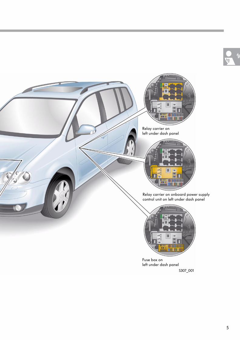
The onboard power supply of the Touran is decentralised. For this reason, the fuse boxes and relay slots are installed at various locations in the vehicle.
The adjacent diagram shows the various fitting locations.
Fuse boxes and relay slots in vehicle's electrical system
Back-up fuse box on leftin engine compartment
Electrics box on left in engine compartment
5
Fuse box on left under dash panel
S307_001
Relay carrier on onboard power supply control unit on left under dash panel
Relay carrier on left under dash panel
6
The networking concept
Overview of networked control units
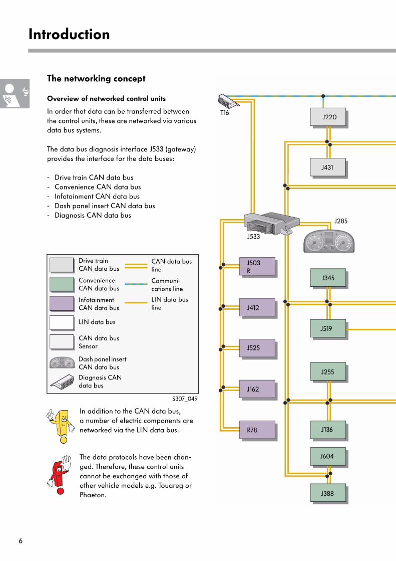
In order that data can be transferred between the control units, these are networked via various data bus systems.
The data bus diagnosis interface J533 (gateway) provides the interface for the data buses:
- Drive train CAN data bus- Convenience CAN data bus- Infotainment CAN data bus- Dash panel insert CAN data bus- Diagnosis CAN data bus
Introduction
S307_049
LIN data bus
Drive train CAN data bus
Convenience CAN data bus
Infotainment CAN data bus
CAN data bus line
Communi-cations line
LIN data bus line
Dash panel insert CAN data bus
Diagnosis CAN data bus
In addition to the CAN data bus, a number of electric components are networked via the LIN data bus.
The data protocols have been chan-ged. Therefore, these control units cannot be exchanged with those of other vehicle models e.g. Touareg or Phaeton.
J503 R
J412
J525
J162
R78
J533
T16J220
J519
J345
J255
J136
J285
J431
J388
J604
CAN data busSensor
7
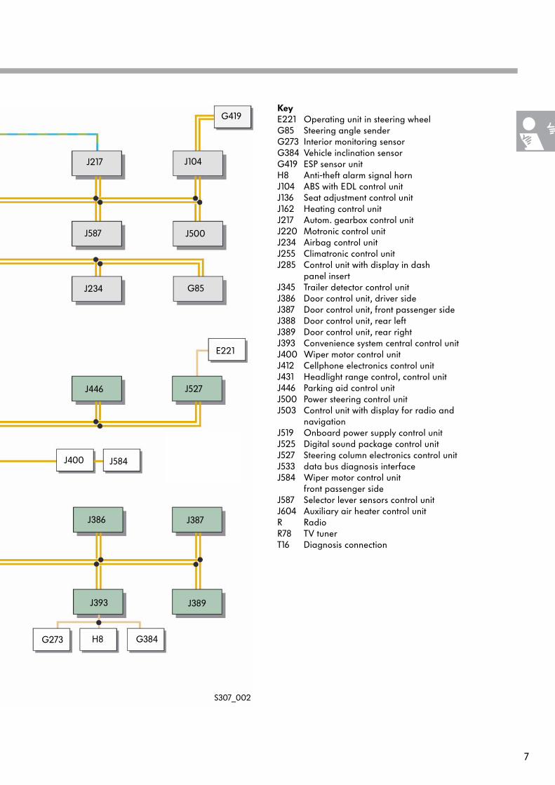
KeyE221 Operating unit in steering wheelG85 Steering angle senderG273 Interior monitoring sensorG384 Vehicle inclination sensorG419 ESP sensor unitH8 Anti-theft alarm signal hornJ104 ABS with EDL control unitJ136 Seat adjustment control unitJ162 Heating control unitJ217 Autom. gearbox control unitJ220 Motronic control unitJ234 Airbag control unitJ255 Climatronic control unitJ285 Control unit with display in dash
panel insertJ345 Trailer detector control unitJ386 Door control unit, driver sideJ387 Door control unit, front passenger sideJ388 Door control unit, rear leftJ389 Door control unit, rear rightJ393 Convenience system central control unitJ400 Wiper motor control unitJ412 Cellphone electronics control unitJ431 Headlight range control, control unitJ446 Parking aid control unitJ500 Power steering control unitJ503 Control unit with display for radio and
navigationJ519 Onboard power supply control unitJ525 Digital sound package control unitJ527 Steering column electronics control unitJ533 data bus diagnosis interfaceJ584 Wiper motor control unit
front passenger sideJ587 Selector lever sensors control unitJ604 Auxiliary air heater control unitR RadioR78 TV tunerT16 Diagnosis connection
J217 J104
J234 G85
J446
G419
J527
J386
J393
J387
J389
G273 H8 G384
E221
J500J587
J400 J584
S307_002

8
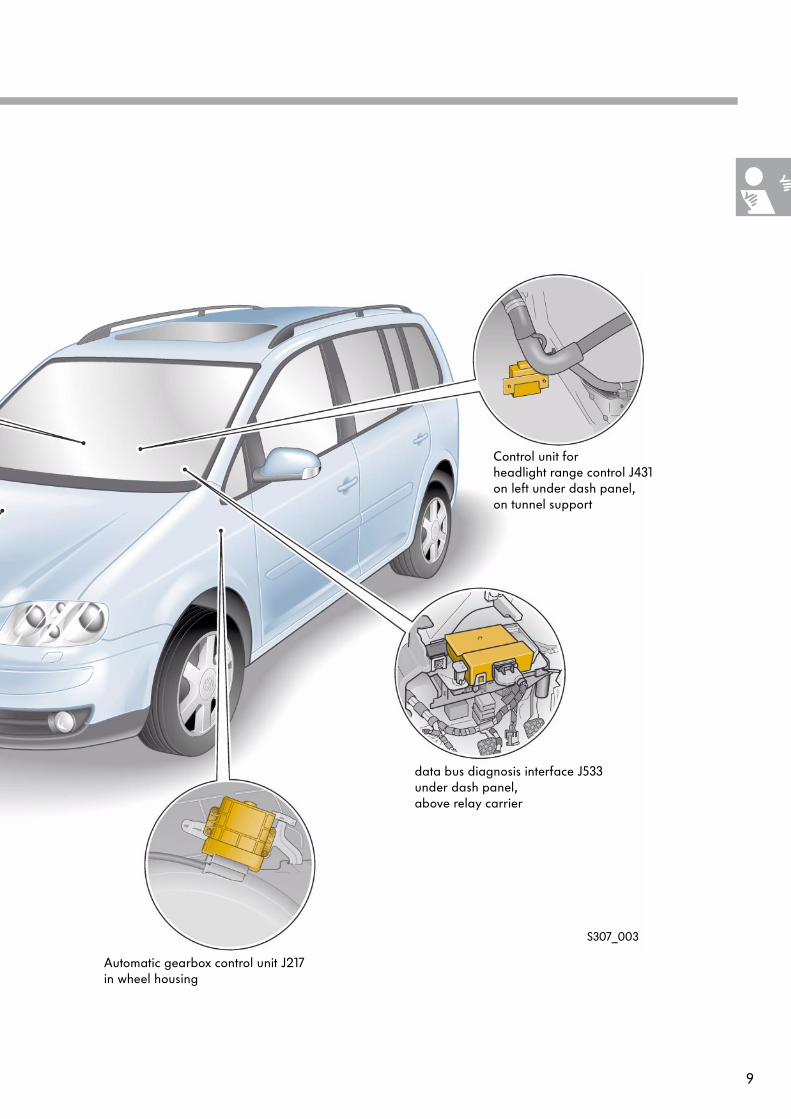
Control units and fitting locations
The adjacent diagram shows the controlunits that belong to the drive train CAN data bus and associated fitting locations.
The data is transferred at a speed of 500 kbit/s. Transfer is made via the orange/black CAN high line and orange/brown CAN low line. To make data transfer more efficient,the CAN lines are entwined.
Introduction
Control units in drive train CAN data bus
Motronic control unit J220under plenum chamber cover
ABS with EDL control unit J104under bulkhead inengine compartment
Airbag control unit J234under centre console
9
S307_003
Control unit for headlight range control J431on left under dash panel,on tunnel support
data bus diagnosis interface J533under dash panel, above relay carrier
Automatic gearbox control unit J217in wheel housing
10
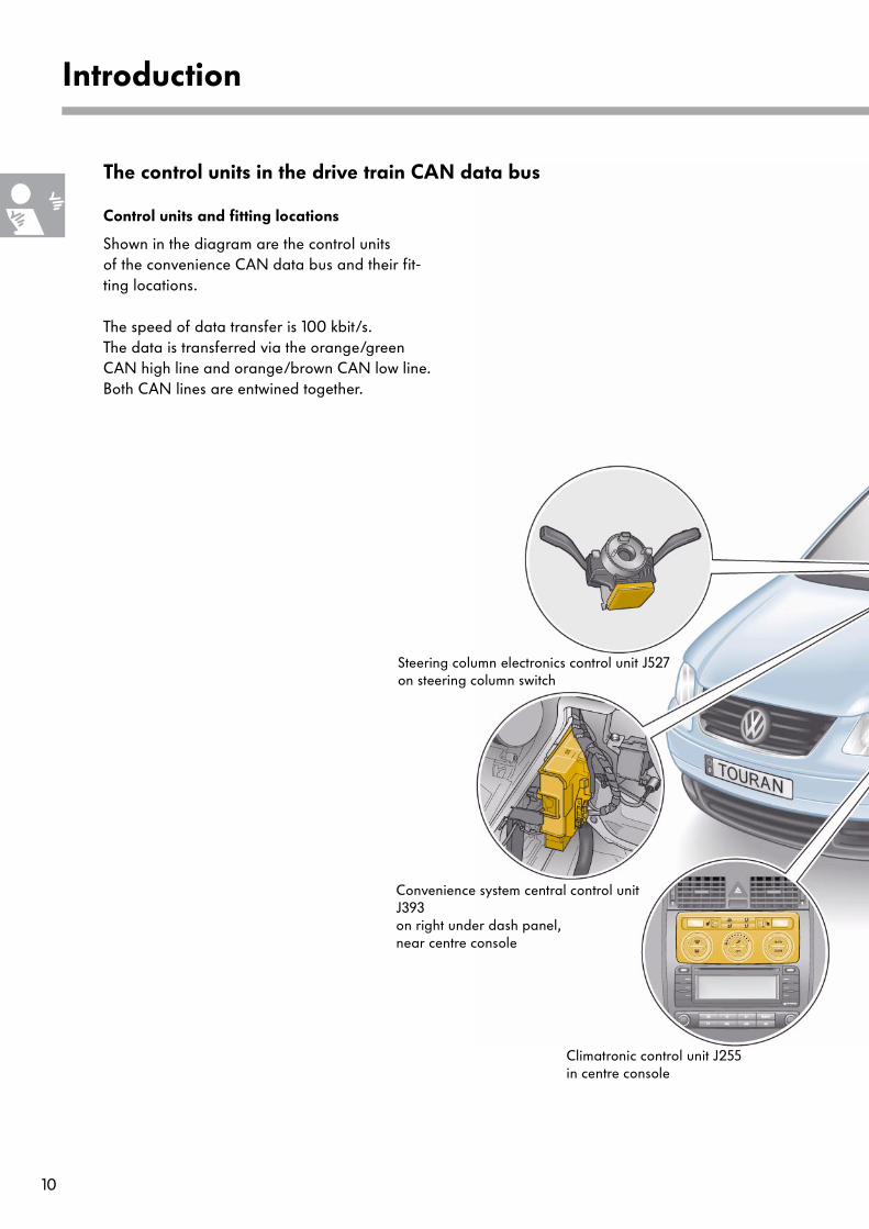
Control units and fitting locations
Shown in the diagram are the control units of the convenience CAN data bus and their fit-ting locations.
The speed of data transfer is 100 kbit/s. The data is transferred via the orange/green CAN high line and orange/brown CAN low line. Both CAN lines are entwined together.
Introduction
Climatronic control unit J255in centre console
Convenience system central control unit J393on right under dash panel, near centre console
Steering column electronics control unit J527on steering column switch
The control units in the drive train CAN data bus

11
S307_004
data bus diagnosis interface J533under dash panel, above relay carrier
Onboard power supply control unit J519under dash panel, on relay carrier
Door control units J386, J387, J388, J389in doors
Trailer detector control unit J345in rear right side part
Parking aid control unit J446in rear right side part
12
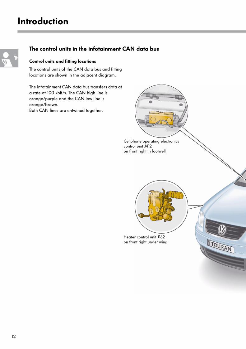
Control units and fitting locations
The control units of the CAN data bus and fitting locations are shown in the adjacent diagram.
The infotainment CAN data bus transfers data at a rate of 100 kbit/s. The CAN high line is orange/purple and the CAN low line is orange/brown. Both CAN lines are entwined together.
Introduction
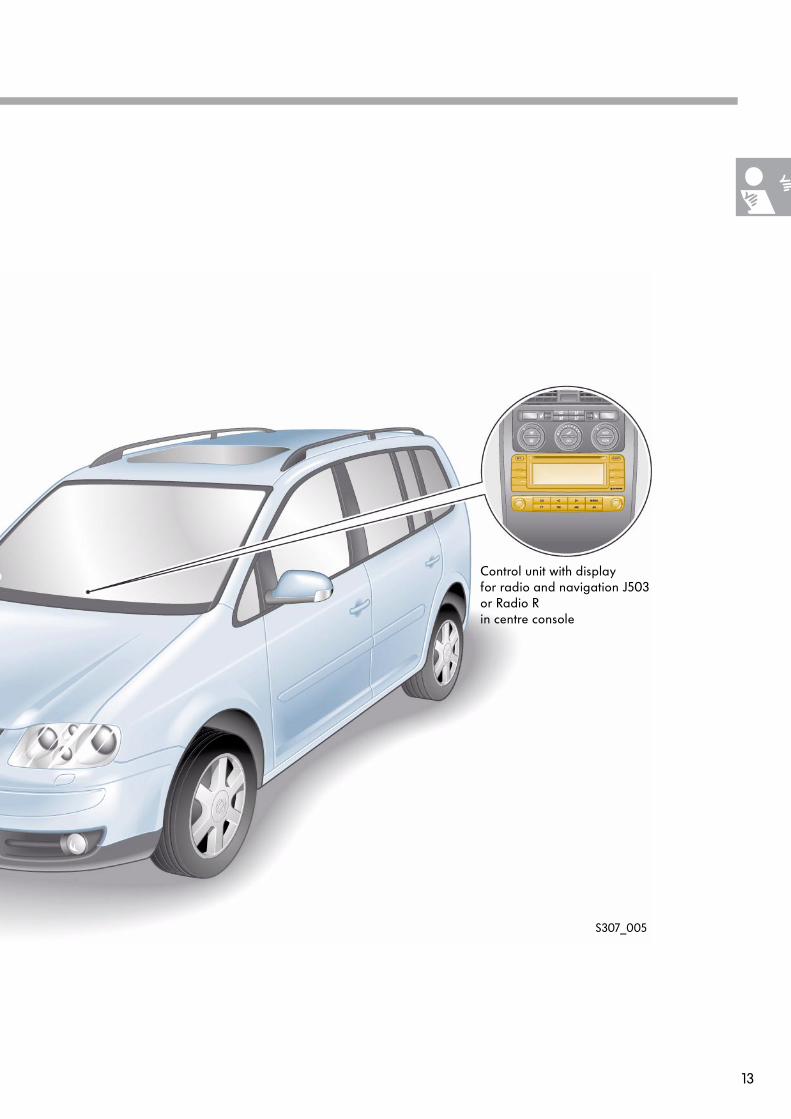
The control units in the infotainment CAN data bus
Cellphone operating electronicscontrol unit J412on front right in footwell
Heater control unit J162on front right under wing
13
S307_005
Control unit with display for radio and navigation J503or Radio Rin centre console

14
Dash panel insert CAN data bus
The data bus transfers data from thedash panel insert to the data bus diagnosis inter-face. The control unit with display unit in the dash panel insert and the data bus diagnosis interface are the only control units attached to this data bus.
Diagnosis CAN data bus
Data transfer between the diagnosis connection T16 and the data bus diagnosis interface is via the diagnosis CAN data bus.
Rate of data transfer
The rate at which data is transferred is 500 kbit/s for both CAN data buses.
Introduction
The control units in the dash panel insert CAN data bus and in the diagnosis CAN data bus
Control unit with display unit in dash panel J285
The dash panel insert CAN data bus and the diagnosis CAN data bus are new data bus connections in the Volkswagen Touran.

15
S307_006
data bus diagnosis interface J533under dash panel, above relay carrier
T16 Diagnosis connectionon left in footwell

16
The LIN data bus as sub data bus system
General description
A sub data bus system connects control units with their electrical components. Among these com-ponents are, for example, control units, switches, sensors, actuators etc. This type of connection and data transfer is used in the Volkswagen Tou-ran for a number of systems.
As a sub data bus system, the LIN data bus has an advantage in cost.The designation LIN stands for local interconnect network, and it means that all the associated electrical components are within a set and limited area of the vehicle.
It is possible for a number of LIN data bus systems to be installed in a vehicle. They will each have different functions to perform. A LIN data bus system consists of a master con-trol unit and one or more slave control units.
The master control unit is also networked with other control units (apart from slave control units) in the vehicle via the CAN data bus. This permits the transfer of data to other LIN data bus systems and other CAN data bus control units.
LIN data bus
LIN data bus system
CAN busLIN data bus
Convenience system central control unit J393CAN user and LIN master
Anti-theft alarm system horn H8LIN slave
data bus diagnosis interface J533
S307_007
Interior monitoring sensor G273LIN slave
Vehicle inclination sender G384LIN slave

17
Data transfer
The data is transferred at a speed of 1 kbit/s to 20 kbit/s. The rate of data transfer is therefore a maximum of 20% of the rate for convenience or infotainment CAN data buses and is fixed in the software of the LIN master.
This transfer is made via data leads that are vio-let in basic colour with a white identification mark. The cross section of the wire is 0.35 mm2. The LIN data bus is a single wire bus. The data lead is not screened.
Signal level
The signal level of the LIN data buses is either close to battery voltage (UB) (recessive level) or earth (0 Volt) (dominant level).
S307_008
S307_009
UB
0
U
t
Recessive level
Dominant level
18
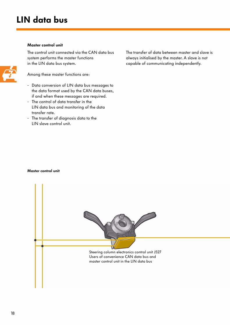
Master control unit
The control unit connected via the CAN data bus system performs the master functionsin the LIN data bus system.
Among these master functions are:
- Data conversion of LIN data bus messages to the data format used by the CAN data buses, if and when these messages are required.
- The control of data transfer in theLIN data bus and monitoring of the data transfer rate.
- The transfer of diagnosis data to theLIN slave control unit.
The transfer of data between master and slave is always initialised by the master. A slave is not capable of communicating independently.
LIN data bus
Master control unit
Steering column electronics control unit J527Users of convenience CAN data bus and master control unit in the LIN data bus
19
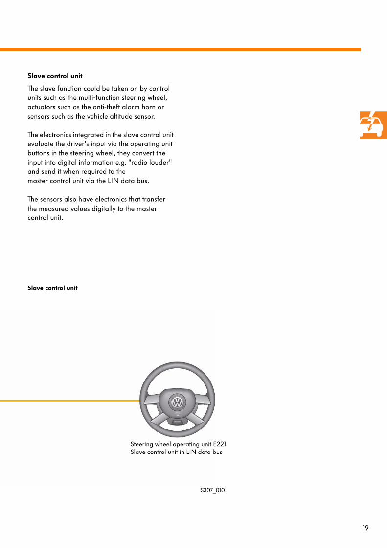
Slave control unit
The slave function could be taken on by control units such as the multi-function steering wheel, actuators such as the anti-theft alarm horn or sensors such as the vehicle altitude sensor.
The electronics integrated in the slave control unit evaluate the driver's input via the operating unit buttons in the steering wheel, they convert the input into digital information e.g. "radio louder" and send it when required to the master control unit via the LIN data bus.
The sensors also have electronics that transfer the measured values digitally to the master control unit.
Slave control unit
S307_010
Steering wheel operating unit E221Slave control unit in LIN data bus
20
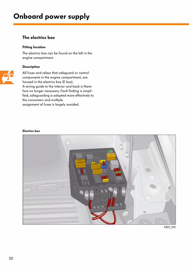
The electrics box
Fitting location
The electrics box can be found on the left in the engine compartment.
Description
All fuses and relays that safeguard or control components in the engine compartment, are housed in the electrics box (E box). A wiring guide to the interior and back is there-fore no longer necessary. Fault finding is simpli-fied, safeguarding is adapted more effectively to the consumers and multipleassignment of fuses is largely avoided.
Onboard power supply
S307_012
Electrics box

21
Electrics box
In addition to the fuses for components in the engine compartment, the electrics box has the following relays:
● Power supply relay terminal 15 J329● Power supply relay terminal 50 J682● Glow plug relay J52● Motronic power supply relay J271● Power supply relay J317
Back-up fuse box
The back-up fuse box houses fuses for the follo-wing:
● alternator,● electro-mechanical power steering,● radiator fan,● auxiliary heater.
S307_052
S307_053

22
Fitting location
In the interior, on the left under the dash panel, you can find the relay carrier, the relay carrier on the onboard power supply control unit and the fuse box.
Onboard power supply
S307_013
Relay carrier and fuse box in interior
The relay carrier and the fuse box in the interior

23
Relay carrier
The relay carrier accommodates additional relays and fuses from optional extras in the vehicle.
Relay carrier on onboard power supply control unit
The following relays can be found on the onboard power supply control unit relay carrier.
● Power supply relay terminal 30G● Heated rear window relay J9● Horn relay J413● Double washer pump relay 1 (front) J729● Double washer pump relay 2 (rear) J730● X contact relief relay J59
Fuse box
Included in the fuse box are the fuses for the electrical components in the vehicle.
For the latest terminal assignment details about the fuse box, please refer to ELSA.
S307_054
S307_055
S307_056

24
Description
Due to the high level of network functions, a great deal of data is transferred. To assure the effective exchange of data, several data bus systems are necessary that transfer data between each other. The data bus diagnosis interface connects these data buses together as a gateway interface and makes data transfer possible. This function that was perviously integrated in the dash panel insert or onboard power supply control unit, is now an independent control unit.
Data bus diagnosis interface
The data bus diagnosis interface J533
Drive train CAN data bus
Convenience CAN data bus
Diagnosis CAN data bus
Dash panel insert CAN data bus
Data transfer
Diagnosis connection
data bus diagnosis interface
25
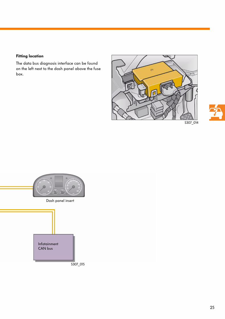
Fitting location
The data bus diagnosis interface can be found on the left next to the dash panel above the fuse box.
S307_015
S307_014
Dash panel insert
Infotainment CAN bus

26
Master functions
Terminal 15 run-on
Certain control units in the CAN data bus need to exchange information even when terminal 15 is off. For this reason, a message is sent to the CAN data bus for actuation of the run-on mode. The control units make a connection from termi-nal 30 to terminal 15 internally, which allows them to communicate further. In this way, the power steering control unit J500, for example, can communicate with the other control units.
The run-on mode can last between ten seconds and fifteen minutes. The run-on period depends on the data that is to be sent.
To finish the run-on period, the data bus diagno-sis interface initiates the sleep command.
data bus diagnosis interface
S307_047
J533
J104
J220
J217
Drive train CAN data bus
Term. 30
Internally switched terminal 15
The data bus diagnosis interface J533 manages the master functions for terminal 15 run-on on the drive train CAN data bus and control of the sleep and wake-up modes for the data bus systems.
Control units that participate in terminal 15 run-on
KeyG85 Steering angle senderJ104 ABS with EDL control unitJ217 Automatic gearbox control unitJ220 Motronic control unitJ271 Motronic power supply relay
J500 Power steering control unitJ587 Selector lever sensors control unitJ533 data bus diagnosis interface
G85
J500
J587
J271
27
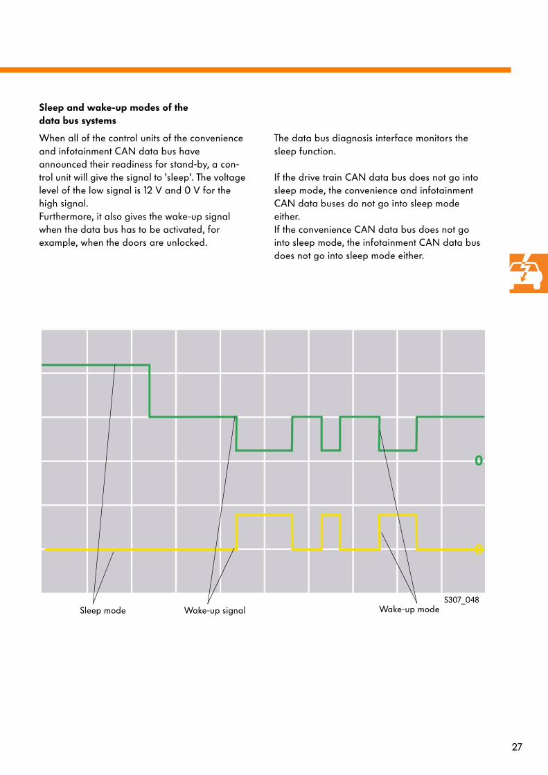
Sleep and wake-up modes of thedata bus systems
When all of the control units of the convenience and infotainment CAN data bus have announced their readiness for stand-by, a con-trol unit will give the signal to 'sleep'. The voltage level of the low signal is 12 V and 0 V for the high signal.Furthermore, it also gives the wake-up signal when the data bus has to be activated, for example, when the doors are unlocked.
The data bus diagnosis interface monitors the sleep function.
If the drive train CAN data bus does not go into sleep mode, the convenience and infotainment CAN data buses do not go into sleep mode either.If the convenience CAN data bus does not go into sleep mode, the infotainment CAN data bus does not go into sleep mode either.
S307_048Sleep mode Wake-up modeWake-up signal
28
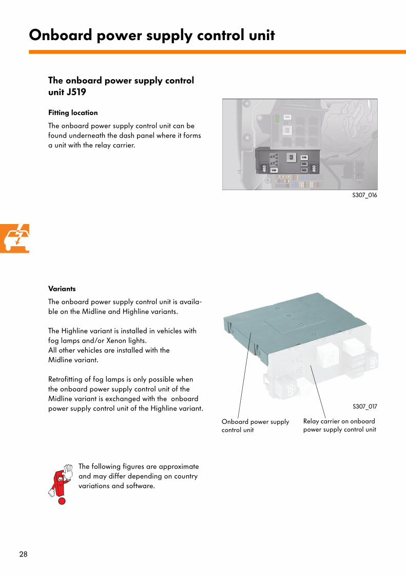
The onboard power supply control unit J519
Fitting location
The onboard power supply control unit can be found underneath the dash panel where it forms a unit with the relay carrier.
Variants
The onboard power supply control unit is availa-ble on the Midline and Highline variants.
The Highline variant is installed in vehicles with fog lamps and/or Xenon lights. All other vehicles are installed with the Midline variant.
Retrofitting of fog lamps is only possible when the onboard power supply control unit of the Midline variant is exchanged with the onboard power supply control unit of the Highline variant.
Onboard power supply control unit
S307_016
S307_017
The following figures are approximate and may differ depending on country variations and software.
Onboard power supply control unit
Relay carrier on onboard power supply control unit

29
Tasks:
- Electric load management
- Functional readinessThe onboard power supply control unit activa-tes the function of the electric sliding/tilting sunroof.
- Exterior light control
- Turn signal control
- Windscreen wipersConveyance of data bus signals to wiper motor control unit
- Rear window wiper
- Heated rear windowActuation of the heated rear window is via the onboard power supply control unit when the heated rear window button is pressed and if the alternator provides enough voltage.
- Interior light controlTerminal 30G, via which voltage is supplied to the interior lights, is activated by the onboard power supply control unit.
- BacklightThe backlight for the footwell is actuated by the onboard power supply control unit via a pulse width modulated signal depending on the position of the dimmer switch for switches and instruments.
- Terminal actuationThe onboard power supply control unit con-trols terminal 75x via an X contact reliefrelay.Terminal 15 is actuated via the voltage supplyrelay for term. 15 in the electrics box and on the onboard power supply control unit relay carrier.Terminal 50 is actuated via the powersupply relay for terminal 50 in theelectrics box.
- Dimmer, instrument backlightTerm. 58d has a dimming function and supp-lies the dimmer switches and instruments with voltage.
- Fuel pump readinessWhen the driver's door is opened, the electri-cal fuel pump is supplied with power by the onboard power supply control unit. As soon as the engine has started, power is supplied by the engine control unit.
- Alternator readinessThe alternator is made ready by the onboard power supply control unit.
The onboard power supply control unit actuates and controls the following functions:

30
Electrical load management
The electrical load management assures that there is always enough energy in the battery to turn the engine over.
To enable this, the electrical consumersof the convenience system are deactivated. The standard of technical safety remains.
To switch off the consumers, the onboard power supply control unit evaluates the engine speed, the battery voltage and the alternator load via the DF signal (dynamo field).
From this information and from information about which consumers are switched on with short activation periods, the onboard power sup-ply control unit carries out an evaluation of the onboard power supply load state.
Based on this evaluation, the onboard power supply control unit can increase engine speed via the engine control unit. The deactivation of con-venience consumers is still possible in the same way.
For load management, three different operating modes are recognised.
Operating mode 1
Terminal 15 on and alternator active
Measures:
At a battery voltage below 12.7 Volt, the onboard power supply control unit demands an increase in the engine idling speed.
At a battery voltage below 12.2 Volt, the follo-wing consumers are switched off:
- Heated seats- Heated windscreen- Heated exterior mirrors- Steering wheel heating- Footwell lighting- Inner door handle lights- Reduction and deactivation of Climatronic- Warning and deactivation of infotainment
Onboard power supply control unit
31
Operating mode 2
Terminal 15 on andalternator inactive
Measures:
At a battery voltage below 12.2 Volt, the follo-wing consumers are switched off:
- Reduction and deactivation of air conditioning- Footwell lighting- Inner door handle lights- Entry/exit lights- Leaving home- Warning and deactivation of infotainment
Operating mode 3
Terminal 15 off andalternator inactive
Measures:
At a battery voltage below 11.8 Volt, the following consumers are switched off:
- Interior lights- Footwell lighting- Inner door handle lights- Entry/exit lights- Leaving home - Infotainment, e.g. radio
When deactivation takes place, this will be shown in the dash panel insert. In addition, an entry will be made in the onboard power supply control unit fault memory.
The differences in deactivation in the various operating modes is in the order of individual consumer deactivation. Furthermore, in operating mode 3, several consumers can be deactivation at once.
Deactivation is cancelled when the conditions for deactivation are no longer met.

32
Exterior light control
The onboard power supply control unit evaluates the signals directly from the light switch. Informa-tion about actuation of the turn signals, main beam and headlight flashing is sent via the stee-ring column electronics control unit J527 to the convenience CAN data bus.
Onboard power supply control unit
Functional diagram
S307_019
KeyD Ignition/starter switch terminal 15E1 Light switchE4 Manual dipped beam and flash switchE19 Parking light switch
F Brake light switchF4 Reverse light switchJ519 Onboard power supply control unitJ527 Steering column electronics control unitM25 High level brake light bulbX Number plate light
E4
E19
D
F4
F
Term. 15
X
J519
J527
M25
Convenience CAN data bus
33
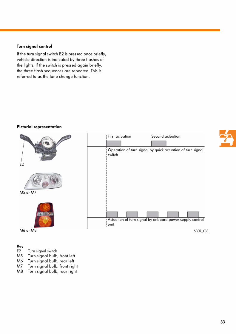
Turn signal control
If the turn signal switch E2 is pressed once briefly, vehicle direction is indicated by three flashes of the lights. If the switch is pressed again briefly, the three flash sequences are repeated. This is referred to as the lane change function.
S307_018
Operation of turn signal by quick actuation of turn signal switch
Actuation of turn signal by onboard power supply control unit
First actuation Second actuation
E2
M5 or M7
M6 or M8
Pictorial representation
KeyE2 Turn signal switchM5 Turn signal bulb, front leftM6 Turn signal bulb, rear leftM7 Turn signal bulb, front rightM8 Turn signal bulb, rear right

34
Monitoring of light switch positions
Light switch E1 is supplied with power directly from the battery. Therefore, it sends a fixed plau-sible signal in every position to the onboard power supply control unit. By way of independent signal input, the onboard power supply control unit can detect whether ignition is switched on or not. If the fixed plausible signal is changed by a fault, such as an open circuit in the wiring, it will change to implausible. The onboard power supply control unit will switch to emer-gency light control.
Onboard power supply control unit
S307_020
E 1
J519
Rear light cluster
Headlights
Signal sequence
KeyE1 Light switchJ519 Onboard power supply control unitTerm. 56 Driving lightsTerm. 58 Side lightsTerm. TFL Daylight driving lights
Function must be coded in onboard powersupply control unit Coding differs in each country.
NSL Rear fog lampNL Fog lights
Term. 58
Term. 56Term. TFL
Term. NL
Term. NSL
Term. 15
Term. 30

35
Emergency light control
Switch position Terminal 58 Terminal 56 Terminal TFL Signal
Off 0 V 0 V 12 V Plausible
Side lights on 12 V 0 V 0 V Plausible
Driving lights on
0 V 12 V 0 V Plausible
Off 0 V 12 V 12 V Implausiblefault detec-tion
Off 0 V 0 V 0 V Implausiblefault detec-tion
Off 12 V 12 V 0 V Implausiblefault detec-tion
Off 12 V 12 V 12 V Implausiblefault detec-tion
Example of light switch plausibility with ignition switched on
If the onboard power supply control unit detects a fault with the ignition switched on, the side lights and the dipped beam lights are switched on.
In the case of all faults, an entry is made in the fault memory.
36
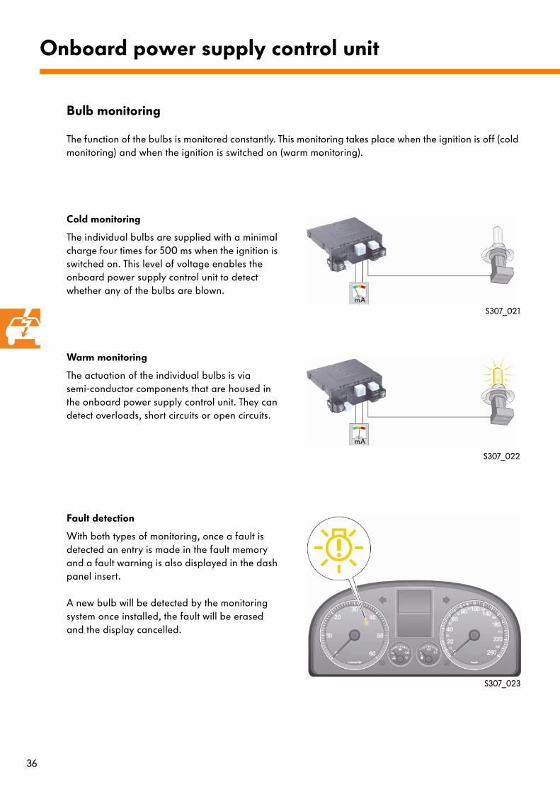
Bulb monitoring
Cold monitoring
The individual bulbs are supplied with a minimal charge four times for 500 ms when the ignition is switched on. This level of voltage enables the onboard power supply control unit to detect whether any of the bulbs are blown.
Warm monitoring
The actuation of the individual bulbs is via semi-conductor components that are housed in the onboard power supply control unit. They can detect overloads, short circuits or open circuits.
Fault detection
With both types of monitoring, once a fault is detected an entry is made in the fault memory and a fault warning is also displayed in the dash panel insert.
A new bulb will be detected by the monitoring system once installed, the fault will be erased and the display cancelled.
Onboard power supply control unit
S307_021
S307_022
S307_023
mA
mA
The function of the bulbs is monitored constantly. This monitoring takes place when the ignition is off (cold monitoring) and when the ignition is switched on (warm monitoring).

37
Additional bulb functions
Bulb Additional function
Dipped beam, left and right
Dimmed daylight dri-ving lights, left and right
Bulb Additional function
Brake light, left and right
Dimmed rear lights, left and rightapprox. 18 %
Rear fog lamp left and rightcountry-specific
Dimmed rear lights,left and rightapprox. 12 %
S307_024
Additional function: Brake light as rear light
Onboard power supply control unit
Rear light cluster
Dimmed actuation of brake lights
Actuation of brake lights for braking
Various bulbs are dimmed to take on additional functions. If their proper function is needed, this is given priority.
Please observe the country-specific variations in the rear fog light function.

38
Wiper motor actuation
Windscreen wiper motor actuation
The wiper system consists of a twin motor oppo-sing action system without a mechanical connec-tion between the wiper arms.
The switch position of wiper switch E is sent directly to the steering column electronics control unit J527 and then via the convenience CAN data bus to the onboard power supply control unit J519.
Information about the selected wiper stage is sent from the onboard power supply control unit via the LIN data bus to the wiper motor control unit J400 and from there to the wiper control unit, front passenger side J584. Both control units are located directly on the wiper motors.
The wiper motor control unit J400 manages control of the wiper motion and regulates the wiper control unit, front passenger side J584.
Windscreen wiper system
S307_025
Actuation of wiper motors
Convenience CAN data bus
LIN data bus
J584
J400
J527
E J519
KeyD Ignition/starter switchE Wiper switchF266 Bonnet contact switchJ400 Wiper motor control unitJ519 Onboard power supply control unit
J527 Steering column electronics control unitJ533 data bus diagnosis interfaceJ584 Wiper control unit, front passenger side
J533
Drive train CAN data busRoad speed
F266
Term. 15
D
Dash panel insertCAN data busAmbient temperature

39
Wiper functions
The wiper system features the following functions:
- Service and winter position- Alternating rest position- Speed dependent wiper stage reset- Speed dependent intermittent delay- Bonnet contact- Synchronisation function- Tip wiping stage 2- Prewash- Follow up wash after wash/wipe function- Trickle wipe - Anti-blocking function- Wiper control for rear window
Service and winter position
If within 10 seconds after switching off the igni-tion, and with the vehicle stationary, the wiper switch is switched to the tip wiping position, the wipers move to the upper arc position. This function cannot be selected when the bonnet is open.
S307_026
Service and winter position

40
Alternating rest position
In order to prevent a permanent deformation of the wiper blades, the wiper arms move upwards slightly every second time they are swit-ched off. In this way, the position of the wiper blades is changed.In addition, the rest position can also be altered by switching the ignition off several times.
Speed dependent wiper stage reset
If the road speed drops below 4 km/h, the selec-ted wiper speed will be reduced by one stage. When road speeds increases above 8 km/h, the wiper speed is reset to the selected stage.
Resetting:
Stage 2 to stage 1
- Terminal 15 on- Wiper switch at stage 2 - Road speed < 4 km/h
Stage 1 to intermittent operation stage
- Terminal 15 on- Wiper switch at stage 1 - Road speed < 4 km/h
(Intermittent delay 4 s)
Windscreen wiper system
S307_027
S307_028
Rest position after swit-ching off first time
Rest position after swit-ching off second time
For reasons of clarity, only the driver's wiper is shown.
41
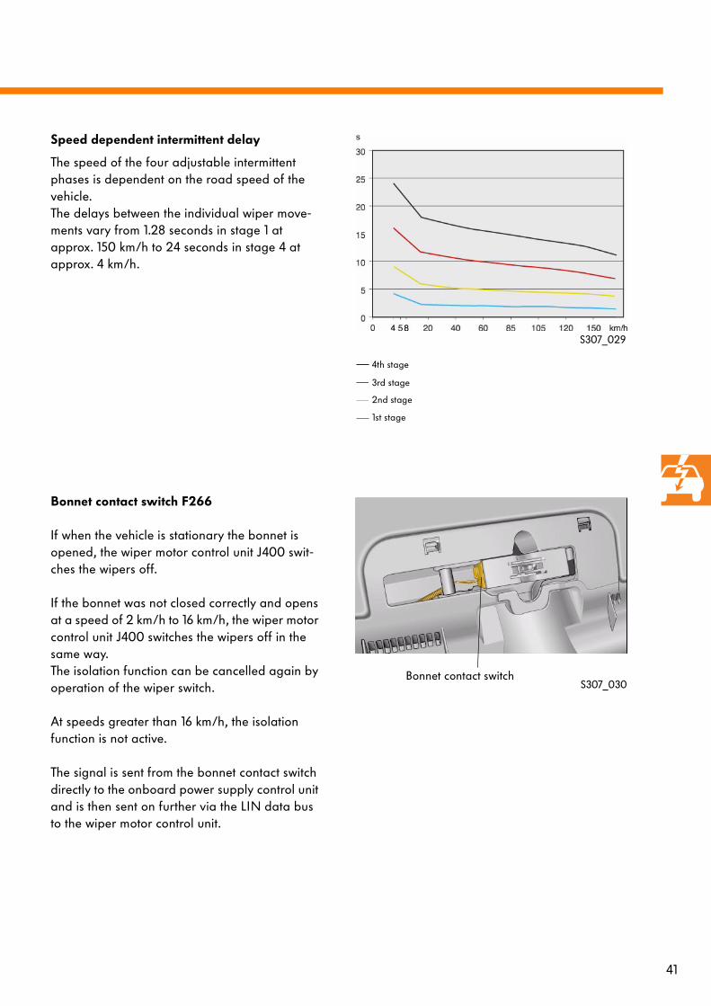
Speed dependent intermittent delay
The speed of the four adjustable intermittent phases is dependent on the road speed of the vehicle. The delays between the individual wiper move-ments vary from 1.28 seconds in stage 1 at approx. 150 km/h to 24 seconds in stage 4 at approx. 4 km/h.
Bonnet contact switch F266
If when the vehicle is stationary the bonnet is opened, the wiper motor control unit J400 swit-ches the wipers off.
If the bonnet was not closed correctly and opens at a speed of 2 km/h to 16 km/h, the wiper motor control unit J400 switches the wipers off in the same way. The isolation function can be cancelled again by operation of the wiper switch.
At speeds greater than 16 km/h, the isolation function is not active.
The signal is sent from the bonnet contact switch directly to the onboard power supply control unit and is then sent on further via the LIN data bus to the wiper motor control unit.
S307_029
S307_030Bonnet contact switch
1st stage
2nd stage
3rd stage
4th stage

42
Synchronisation function
If the windscreen wipers are not in their rest posi-tion when the ignition is switched off, these will be moved automatically to the rest position when the ignition is switched on and when the wiper switch E4 is actuated. This is either a parallel or individual movement.A system with an unsynchronised rest position is set straight with this procedure.
Tip wiping stage 2
If the tip wiping function is actuated for longer than two seconds, the wiper is switched to the second stage.
Windscreen wiper system
S307_031
S307_032
Wiper paths during synchronisation
43
Prewash
When the wash/wipe function is actuated at speeds less than 120 km/h, the wiper will begin to operate after a prewash period of approx. 0.8 seconds, during which only the washer pump is active.
Follow up wash after wash/wipe function
If the wash/wipe function is actuated for longer than 0.5 seconds, the follow up wiping function is actuated three times. If actuation time is less, follow up wiping is actuated twice.
Trickle wiping
If the road speed of the vehicle is greater than 2 km/h, the wiper function is actuated once more 5 seconds after the last follow up wash (follow up wiping cycle).
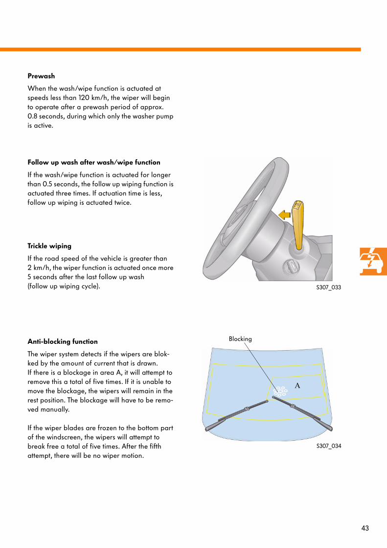
Anti-blocking function
The wiper system detects if the wipers are blok-ked by the amount of current that is drawn. If there is a blockage in area A, it will attempt to remove this a total of five times. If it is unable to move the blockage, the wipers will remain in the rest position. The blockage will have to be remo-ved manually.
If the wiper blades are frozen to the bottom part of the windscreen, the wipers will attempt to break free a total of five times. After the fifth attempt, there will be no wiper motion.
S307_033
S307_034
Blocking
A

44
Rear window wiper control
Rear window wiper actuation features three ope-rating modes:
- Reverse wiping- Rear intermittent wiping- Rear window wash/wipe operation
Reverse wiping
The reverse wiping function actuates the rear window wiper to clear the screen if, when the front windscreen wiper is switched on, reverse gear is selected.
Intermittent stage One wipeStage 1 or 2 Rear intermittent wipe
Conditions for activation:
- Ignition switched on- Windscreen wiper is in intermittent stage 1 or
stage 2 Recognition of the selected stage is via the convenience CAN data bus. The signal comes from the steering columnelectronics control unit.
- Reverse gear or R selected Recognition is via the reverse light switch or via the gear selector position, the automatic gearbox control unit, the drive train CAN data bus, the data bus diagnosis interface and the convenience CAN data bus.
- Tailgate closedRecognition is via the convenience system cen-tral control unit.
Rear window wiper system
Convenience CAN bus
S307_035
E
V12
J519
Signal pattern of rear window wiper
J527
J533
J393
Drive train CAN data bus
Information about selected reverse gear
KeyD Ignition/starter switchE Wiper switchJ393 Convenience system central control unitJ519 Onboard power supply control unit
J527 Steering column electronics control unitJ533 data bus diagnosis interfaceV12 Rear window wiper motor
D
Term. 15

45
Rear intermittent wiping
If the rear intermittent wiper stage is selected, the rear window wiper operates in delayed stages.
Conditions for activation:
- Ignition switched on- Rear window intermittent wiper stage on:
Recognition is via the wiper switch, the stee-ring column electronics control unit and the convenience CAN data bus.
- Tailgate closedRecognition is via the convenience system cen-tral control unit.
Rear window wash/wipe operation
In rear window wash/wipe operation, the double washer pump delivers washer water to the rear window and the rear window is cleared.
Conditions for activation:
- Ignition switched on- Rear window wash/wipe operation stage on:
Recognition is via the wiper switch,the steering column electronics control unit and the convenience CAN data bus.
- Tailgate closed:Recognition is via the convenience system cen-tral control unit.
S307_036
S307_037
46
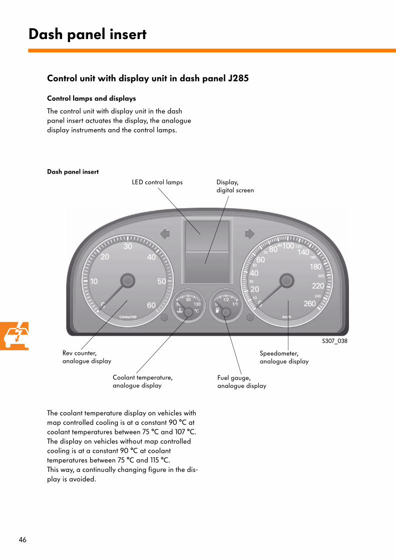
Control lamps and displays
The control unit with display unit in the dash panel insert actuates the display, the analogue display instruments and the control lamps.
The coolant temperature display on vehicles with map controlled cooling is at a constant 90 °C at coolant temperatures between 75 °C and 107 °C. The display on vehicles without map controlled cooling is at a constant 90 °C at coolanttemperatures between 75 °C and 115 °C. This way, a continually changing figure in the dis-play is avoided.
Dash panel insert
S307_038
Control unit with display unit in dash panel J285
Dash panel insert
Rev counter, analogue display
Speedometer, analogue display
Coolant temperature, analogue display
Fuel gauge, analogue display
Display, digital screen
LED control lamps

47
Display
The following variants are designed for the display:
Lowline with displays for
- Clock- Mileage reader- Trip counter- Selector lever position
Midline with additional displays to Lowline variant
- Ambient temperature- Multi-function display or - Warning messages instead of multi-function
display and ambient temperature
Highline with additional displays to Midline variant
- Sender display- Warning symbols instead of multi-function dis-
play and ambient temperature
S307_039
S307_040
S307_041
20:14
20:14
20:14
km
20375trip
167.5
P R N D S 3
km
20375trip
167.5
km
20375trip
167.5
P R N D S 3
7.8 ltr./100 km
13.5 C°
7.8 ltr./100 km
13.5 C°
Lowline variant
Midline variant
Highline variant
PRNDS2
48
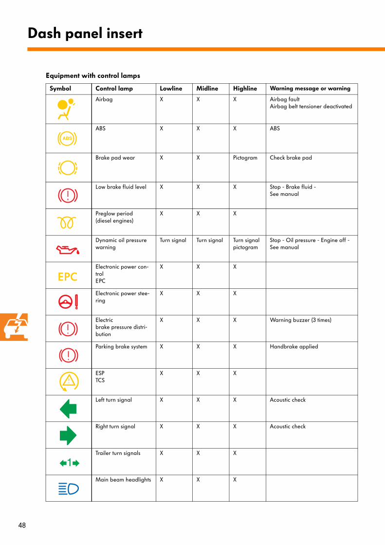
Equipment with control lamps
Symbol Control lamp Lowline Midline Highline Warning message or warning
Airbag X X X Airbag faultAirbag belt tensioner deactivated
ABS X X X ABS
Brake pad wear X X Pictogram Check brake pad
Low brake fluid level X X X Stop - Brake fluid - See manual
Preglow period (diesel engines)
X X X
Dynamic oil pressure warning
Turn signal Turn signal Turn signal pictogram
Stop - Oil pressure - Engine off - See manual
Electronic power con-trolEPC
X X X
Electronic power stee-ring
X X X
Electricbrake pressure distri-bution
X X X Warning buzzer (3 times)
Parking brake system X X X Handbrake applied
ESPTCS
X X X
Left turn signal X X X Acoustic check
Right turn signal X X X Acoustic check
Trailer turn signals X X X
Main beam headlights X X X
Dash panel insert

49
Symbol Control lamp Lowline Midline Highline Warning message or warning
Cruise control system X X X
Bulb failure X X X e.g. Front left dipped beam light defective
Tailgatedoor open
X X Pictogram e.g. Tailgate open
Fuel reserve X X Pictogram Please fill up -Warning buzzer (once)
Low coolant level oroverheating
X X Pictogram Stop - Check coolant See manual -Warning buzzer (3 times)
Alternator X X X
Engine checkEOBD
X X X Engine fault - Workshop -Exhaust gas - Workshop
Bonnet open X X Pictogram Door warning! Bonnet!Warning buzzer (once) if v > 6 km/h
Rear fog light X X X
Oil level X X Pictogram Check oil levelOil sensor - Workshop
Tyre pressure monitor X X X Warning buzzer (once)
Shift lock X X X
Seatbelt X X X Please apply seatbelt -Gong
Low washer water X X Pictogram Replenish washer water -Warning buzzer (once)
Immobiliser Turn signal Turn signal Turn signal Immobiliser active -Warning buzzer (once)

50
Control unit
The immobiliser control unit J362 can be found in the dash panel insert, as with immobilisers of the third generation. The diagnosis connection is made via address word 25. Communication is only possible via the diagnosis CAN data bus with vehicle diagnosis, testing and information system VAS 5051.
Immobiliser
The fourth generation immobiliser
VAS 5051
T16
Diagnosis CAN data bus
Dash panel insert CAN data bus
VAS 5051/5A
Diagnosis
J533
J285
KeyJ285 Control unit with display unit in dash panel insertJ533 data bus diagnosis interfaceVAS 5051 Vehicle diagnosis, testing and information systemVAS 5051/5A Diagnosis lead 3 mT16 Diagnosis connection
S307_042

51
Changes compared to the third generation immobiliser
Brand identification
The immobiliser components of all Group brands are different. Adaption of components from other Group brands in Volkswagen vehicles is not possible.
Preprogrammed key
The vehicle keys are preprogrammed by the manufacturer with a basic code. This basic code includes a specific manufacturer code. Matching the key to a vehicle is only possi-ble if it has the correct manufacturer code.
S307_044
S307_043
Basic code
52
Immobiliser
Matching
Enabling the matching function is done via the vehicle diagnosis, testing and information system VAS 5051. The personal identification number (PIN) for matching is currently available via the dealer online access system (HOLZ). In future, matching will be carried out via an online connection.
Exchanging the engine control unit
The engine control unit is enabled in the same way as the third generation immobiliser. Two of the three adapted components(key and dash panel insert) must remain in the vehicle.
For adaption of a new control unit, this can be done without a personal identification number.
For adaption of a control unit that was previously installed in a different vehicle, a personal identi-fication number is required.

53
Exchanging the dash panel insert
Adaption is carried out in the same way as for the third generation immobiliser. Likewise, two of the three adapted components (key and engine control unit) must remain in the vehicle.
For adaption of a new dash panel insert, this can be done without a personal identification umber.
A personal identification number is required for a previously used dash panel insert.
Following exchange, the immobiliser control unit J362 will detect an unknown key. For this reason, there is a blocking period of five minutes during which time the engine cannot be started.
With the exchange of more than one component, all three items must be renewed as less than two of the mat-ched components are left in the vehicle.
54
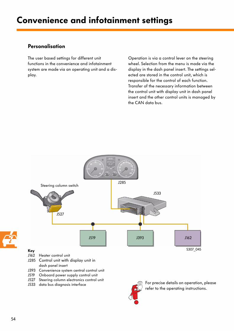
Personalisation
The user based settings for different unit functions in the convenience and infotainment system are made via an operating unit and a dis-play.
Operation is via a control lever on the steering wheel. Selection from the menu is made via the display in the dash panel insert. The settings sel-ected are stored in the control unit, which is responsible for the control of each function. Transfer of the necessary information between the control unit with display unit in dash panel insert and the other control units is managed by the CAN data bus.
Convenience and infotainment settings
S307_045
J527
J519 J393 J162
KeyJ162 Heater control unitJ285 Control unit with display unit in
dash panel insertJ393 Convenience system central control unitJ519 Onboard power supply control unitJ527 Steering column electronics control unitJ533 data bus diagnosis interface
J533
J285Steering column switch
For precise details on operation, please refer to the operating instructions.
55
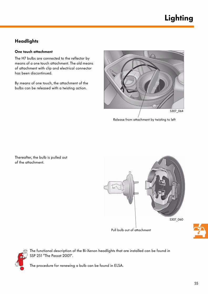
Headlights
One touch attachment
The H7 bulbs are connected to the reflector by means of a one touch attachment. The old means of attachment with clip and electrical connector has been discontinued.
By means of one touch, the attachment of the bulbs can be released with a twisting action.
Thereafter, the bulb is pulled out of the attachment.
Lighting
S307_060
The functional description of the Bi-Xenon headlights that are installed can be found in SSP 251 "The Passat 2001".
The procedure for renewing a bulb can be found in ELSA.
S307_064
Release from attachment by twisting to left
Pull bulb out of attachment
56
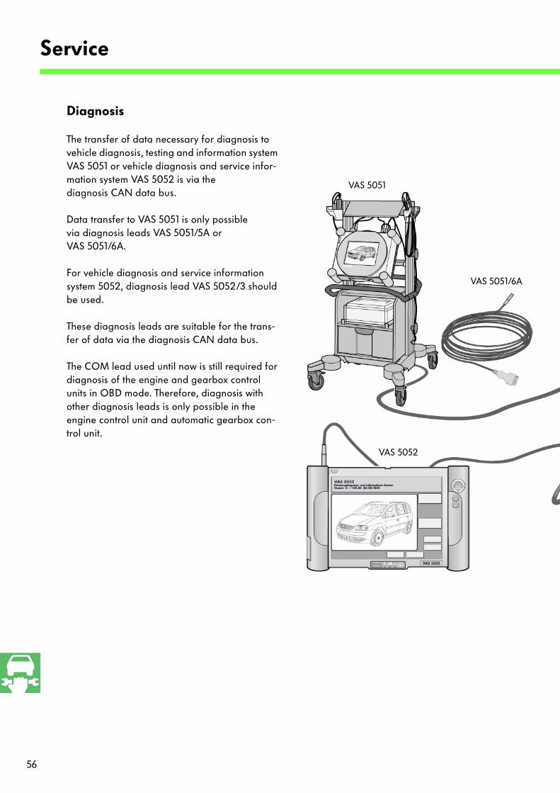
Diagnosis
The transfer of data necessary for diagnosis to vehicle diagnosis, testing and information system VAS 5051 or vehicle diagnosis and service infor-mation system VAS 5052 is via thediagnosis CAN data bus.
Data transfer to VAS 5051 is only possible via diagnosis leads VAS 5051/5A or VAS 5051/6A.
For vehicle diagnosis and service information system 5052, diagnosis lead VAS 5052/3 should be used.
These diagnosis leads are suitable for the trans-fer of data via the diagnosis CAN data bus.
The COM lead used until now is still required for diagnosis of the engine and gearbox control units in OBD mode. Therefore, diagnosis with other diagnosis leads is only possible in the engine control unit and automatic gearbox con-trol unit.
Service
VAS 5051
VAS 5052
VAS 5051/6A
57
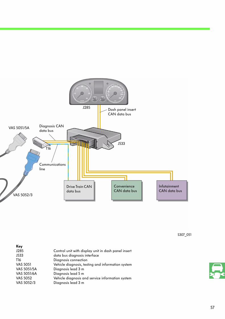
S307_051
KeyJ285 Control unit with display unit in dash panel insertJ533 data bus diagnosis interfaceT16 Diagnosis connectionVAS 5051 Vehicle diagnosis, testing and information system VAS 5051/5A Diagnosis lead 3 mVAS 5051/6A Diagnosis lead 5 m VAS 5052 Vehicle diagnosis and service information systemVAS 5052/3 Diagnosis lead 3 m
Drive Train CAN data bus
Convenience CAN data bus
Infotainment CAN data bus
Dash panel insertCAN data bus
Diagnosis CANdata bus
T16
J285
VAS 5051/5A
Communications line
J533
VAS 5052/3
58
1. Which data bus systems are used in the Volkswagen Touran?
a) The CAN data bus and the LIN data bus.
b) The MOSFET data bus, the LIN data bus and the MOST bus.
c) The D2B data bus, the A data bus and the CAN data bus.
2. Where can the data bus diagnosis interface be found?
a) In the dash panel insert.
b) Under the centre console next to the airbag control unit.
c) Under the dash panel above the relay carrier.
3. Which control units belong to the dash panel insert CAN data bus?
a) The onboard power supply control unit, the automatic gearbox control unit and the trailer detector control unit.
b) The control unit with display unit in dash panel insert and the data bus diagnosis interface.
c) The Motronic control unit and the diagnosis connection.
4. The LIN data bus transfers data at a rate of
a) 1 kbit/s to 20 kbit/s.
b) 100 kbit/s to 500 kbit/s.
c) 21 Mbit/s.
Test yourself

59
5. Which functions are controlled by the onboard power supply control unit?
a) Turn signal control, heated rear window, fuel pump readiness.
b) Windscreen and rear window wipers, central locking, instrument illumination.
c) Load management, alternator readiness, starter isolator.
6. What is the main role of the load management system?
a) To ensure that there is always enough electrical power to turn the engine over.
b) With electronic charge indication, it warns the driver when the vehicle is overcharged.
c) It prevents overloading of the engine by irregular operation.
7. What must be observed when operating the vehicle diagnosis, testing and information system VAS 5051 on the Touran?
a) For diagnosis, only diagnosis leads VAS 5051/5A and VAS 5051/6A should be used.
b) Diagnosis can be carried out in all areas using V.A.G 1551 or V.A.G 1552.
c) Diagnosis is only possible using VAS 9119.
Answers:1. a 2. c 3. b4. a5. a, c6. a7. a

For internal use only © VOLKSWAGEN AG, Wolfsburg
All rights and the right to make technical alterations reserved
000.2811.27.20 Technical status 02/03
❀ This paper was manufactured from pulp that
was bleached without the use of chlorine.
307