the tracker - home — track air
TRANSCRIPT

TRACK'AIRAerial Survey Systems
ZUTPHENSTRAAT 55, 7575 EJ OLDENZAAL, THE NETHERLANDS
Tel +31 - 541 229030 - Fax +31 541 229033 - Hot line +31 6 51363197
Email: [email protected] Internet: http://www.trackair.com
TRACK'AIR © 1995 - 2008
THE TRACKER
snapBASE
Aerial Survey Management Utility
USERS MANUAL

snapBASE aerial survey system
TRACK'AIR © 1995 - 2008
2
• Copyright © by TRACK'AIR, 1994 –2008. All rights reserved.
• TRACKER™ is a trademark of TRACK'AIR.
• This manual, or portion thereof, may not be reproduced in any form without the written permission of TRACK'AIR.
• Windows and Access are trademarks of Microsoft inc.
• Autocad is a trademark of Autodesk inc.
• Other products mentioned herein are the trademarks of their respective owners.

snapBASE aerial survey system
TRACK'AIR © 1995 - 2008
3
TABLE OF CONTENTS
1 - ABOUT THIS MANUAL
2 - OVERVIEW
3 - QUICK TOUR
4 - MAIN TOOLBAR
5 - BUTTONS SHARED BY ALL MODULES
6 - FEATURES SHARED BY ALL MODULES
7 - EDITOR TOOLBAR
8 - EDITOR MODE
9 - PREPARING SUB FLIGHT PLANS
10 - SAVING THE TERRAIN HEIGHT
11 - FLIGHT SEQUENCE
12 - RUN ATTEMPT SIMULATOR
13 - USING QUERIES
14 - DATA MANAGEMENT
15 - EXPORT PROCEDURE
16 - IMPORT PROCEDURE
17 - ARCHIVING
18 - MENUS
19 - REPORTS MENU
20 - CAPTURE MENU
21 - OPTION : FILM ANNOTATION
22 - NOTES
snapBASE aerial survey system
TRACK'AIR © 1995 - 2008
1-1
1 - ABOUT THIS MANUAL
Please note that this manual might not exactly match the software you are using. As the system is being changed and improved all the time, the written material might become slightly different from the current software release. Manuals are regularly updated to reflect changes made to the software. UPDATES
Pages numbers include the chapter number and the page number, E.G. 15 - 3, meaning page 3 of chapter 15. You will receive updates that consist of complete chapters. Simply discard the old chapter pages and replace them with the new chapter. CHAPTERS
Chapters are in no particular orders. Newly written chapters are added at the end of each manual.

snapBASE aerial survey system
TRACK'AIR © 1995 - 2008
2-1
2 - OVERVIEW
Please note that this manual might not exactly match the software you are using. As the system is being changed and improved all the time, the written material might become slightly different from the current software release. Manuals are regularly updated to reflect changes made to the software. The snapBASE module is a management tool that is used to check and keep track of the status and
progress of an aerial photography project. snapBASE is also used to import and export flight plans from the main database to the portable computers’ secondary databases. The main snapBASE functions are:
• Maintain, repair, compress and backup the database
• Export flight plans to the airborne system.
• Create sub flight plans and save them.
• Mark accepted and rejected photography and keep track of the job progress.
• Updates the main database with data collected during the photo flight.
• Archives projects and removes them from the active database.
• Edit the database and change any names and numbers
• Correct film numbering and photo numbering errors
• Exchange flight planning data with other systems.
• Prepare progress reports and film reports.
• Find out about the status of individual photos.

snapBASE aerial survey system
TRACK'AIR © 1995 - 2008
3-1
3 - QUICK TOUR
The following will assist you to run the program the first time and get familiar with its operation. The database contains several examples which can be loaded and edited to practice with the system.
Start the program by clicking the snapBASE icon
Figure 3-1
The load flight plan dialog is used to select a project from the database. It consists of 2 lists, the projects list and the flight plans list. If a name is highlighted in the project list, then the associated flight plans are automatically displayed in the other list.
Figure 3-2
1) Select Check a project?
2) Press OK.
3) Select here the project named Demo your country (as in Demo Australia) or any other project.
2) Select here the flight plan SAMPLE 1 (or any other).
3) Press OK.
snapBASE aerial survey system
TRACK'AIR © 1995 - 2008
3-2
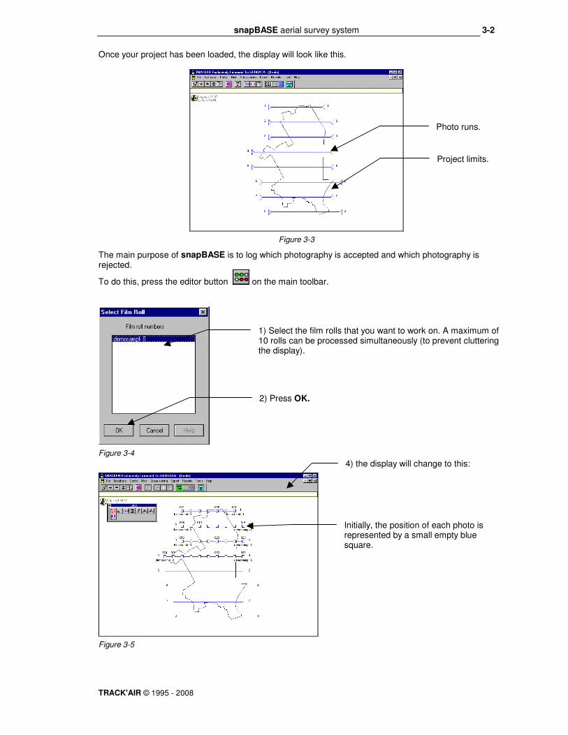
Once your project has been loaded, the display will look like this.
Figure 3-3
The main purpose of snapBASE is to log which photography is accepted and which photography is rejected.
To do this, press the editor button on the main toolbar.
Figure 3-4
Figure 3-5
1) Select the film rolls that you want to work on. A maximum of 10 rolls can be processed simultaneously (to prevent cluttering the display).
2) Press OK.
Initially, the position of each photo is represented by a small empty blue square.
4) the display will change to this:
Photo runs.
Project limits.

snapBASE aerial survey system
TRACK'AIR © 1995 - 2008
3-3
5) There are various methods to flag photos as accepted or rejected. For the moment press the run
attempt button on the small toolbar and click within one of the small blue squares.
Figure 3-6
Figure 3-7
8) You can repeat the same operation for each run. Once this is finished, return to the main display by
clicking the photo index button on the main toolbar.
Figure 3-8
10) To leave the program, press the Exit button .
6) Select the Accept option and press OK.
The photo squares of the selected run are now filled with green, indicating that the photos are accepted.
The current index of accepted photography is now displayed. This index can be printed in snapPLOT.

snapBASE aerial survey system
TRACK'AIR © 1995 - 2008
4-1
4 - MAIN TOOLBAR
Figure 4-1
SAVE.
Save current sub-plan.
TERRAIN HEIGHT.
Press to enter the terrain height mode to save reference terrain height information for each run.
LINE NOT REQUIRED.
Press and click runs which should not be included in the current sub-plan. Clicking a run a
second time will restore it.
END MARKERS.
Press to enter the end markers editing mode to change the position where lines should be
started or ended.
SEQUENCING.
In snapBASE, sequencing is only used by the internal simulator.
EDITOR.
Press to enter the editor mode to accept/reject the photography. In this mode it is also possible
to rename and renumber the film rolls and add/remove individual photo.
INDEX.
Press to show an index of the currently ACCEPTED photography and save all changes to the
database.
EXIT.
Exit the snapBASE application.

snapBASE aerial survey system
TRACK'AIR © 1995 - 2008
5-1
5 - BUTTONS SHARED BY ALL MODULES
The following describes the buttons shared by all the Tracker modules:
REFRESH Click this button to redraw the screen if it has not been properly painted or to remove garbage.
ZOOM IN (REDUCE SIZE). Clicking this button will increase the scale of the drawing. Click until the drawing is at the required size. A beep and no effects will indicate that the limits have been reached. The maximum scale depends on the original size of the area.
ZOOM OUT (ENLARGE). Clicking this button will decrease the scale of the drawing. Click until the drawing is at the required size. A beep and no action will indicate that the limits have been reached. The minimum scale depends on the original size of the area.
RESTORE Clicking this button will restore the drawing to its first size and position.
ZOOM WINDOW. Press this button down and draw a rectangle around the area to be enlarged.
Note: To draw a rectangle, position the mouse pointer on the rectangle upper left corner position, press the mouse button and while keeping it down, drag the mouse towards the right and down. A rectangle is displayed while this operation is taking place, when its size is satisfactory, release the mouse button.
OPEN NEW PROJECT Click this button to return to the project selection dialogue box.
EXIT THE PROGRAM. Click this button to shut down the program.

snapBASE aerial survey system
TRACK'AIR © 1995 - 2008
6-1
6 - FEATURES SHARED BY ALL MODULES
The following describes features and behaviors that are common to all TRACKER modules.
DRAGGING THE DISPLAY
Figure 6-1
GRAPHIC REPRESENTATION OF RUNS
Tracker represents runs and strips by their centerline and crosswise ticks which represents the photo positions.
To move the entire drawing
area, PRESS AND HOLD the LEFT mouse button anywhere on the map area, drag the mouse to an other spot and release the button. The whole map will be shifted. While the mouse button is held down, the cursor changes to a 4 heads arrow.
Center of first photo.
Center of last photo.

snapBASE aerial survey system
TRACK'AIR © 1995 - 2008
7-1
7 - EDITOR TOOLBAR
Figure 7-1
REJECT. Press and click photos to be rejected. To reject a range of photos, point to the first photo and move the mouse pointer to the last photo while holding down the left mouse button.
ACCEPT. Press and click photos to be accepted. To accept a range of photos, point to the first photo and move the mouse pointer to the last photo while holding down the left mouse button.
RUN ATTEMPT INFORMATION. Press and click a photo to show the corresponding run attempt information dialog box.
FILM INFORMATION. Press and click a photo to show the corresponding film information dialog box.
SHOW. Press to show all the run attempts that were previously hidden.
INSERT A PHOTO. If required (for example to correct a malfunction during the photo flight) it is possible to add a photo to the flight. Press this button and point to the photo positioned just before or just after the missing photo, then drag the mouse pointer to the position where the new photo has to be inserted.
REMOVE A PHOTO. If required it is possible to remove a photo from the database system. Press this button, then click the photo to be deleted. To delete a range of photos, point to the first photo and move the mouse pointer to the last photo while holding down the left mouse button. Remark: Normally, this function should never be used. Photos deleted are removed from the system and cannot be recovered or reloaded.
ACTIVATE REJECTION FLAGS. This button displays a list of comments describing the reasons why photography is rejected. These flags are saved in the database with each photo.

snapBASE aerial survey system
TRACK'AIR © 1995 - 2008
8-1
8 - EDITOR MODE
The editor mode groups the functions that allow the user to interact with the database. The following operations can be performed:
• accept single photo, group of photos, run attempts or film rolls.
• Reject single photo, group of photos, run attempt or film roll.
• Add missing photos.
• Delete individual photos.
In addition, it is possible to use the editor mode to change or correct some of the database information.
• Film numbers.
• Photo numbers.
Remark: To save your work, press the photo index button on the main toolbar.
To access the editor mode, load a project and start the editor mode by pressing the editor button . The following dialog will appear:
Figure 8-1
Figure 8-2
Select the film rolls you want to work on. Remark: To prevent cluttering the display, a maximum of 10 rolls can be processed simultaneously. Press OK.
Each film is represented by a different color. Initially the squares are not filled.
In the snapBASE system, photography can only be in one of the following three states: • Flown: Not filled.
• Accepted (OK for printing, delivery, etc.): Filled with green.
• Rejected (not usable): Filled with red.

snapBASE aerial survey system
TRACK'AIR © 1995 - 2008
8-2
ACCEPTING PHOTOGRAPHY
Accepting photography is normally the result of film inspection. This is an essential step in keeping your database functioning and up to date. There are 4 ways to accept photography.
1/2) Press the accept button .
Figure 8-3
3) Press the run attempt button and click a photo belonging to the run attempt you want to accept.
Figure 8-4
4) Press the Film roll button and click a photo belonging to the film you want to accept.
Figure 8-5
This dialog will show up. Select the Accept option
and press OK. The complete run attempt will be accepted in one go.
1) Click individual photos one at a time. Once a photo has been clicked as accepted, it is still possible to click it as rejected.
2) To accept a range of photos in one operation, press the left mouse button on the first photo to be accepted, drag the mouse keeping the button down and release the button over the center of the last photo of the range. During the dragging action, a line will assist you to visualize the selection progress.
This dialog will show up. Select the Accept option and press OK. The complete film will be accepted in one go.

snapBASE aerial survey system
TRACK'AIR © 1995 - 2008
8-3
REJECTING PHOTOGRAPHY
Rejected photography are photos whose quality or coverage do not meet the specifications. In order to
insure a good management of the re-flights, its is necessary to log these photos in the Tracker database system. The procedure to reject photography is exactly similar to the procedure used to accept photography.
Use the reject button . In addition, If you wish to indicate the reason why photos have to be
rejected, press first the rejection flags button and select the cause of rejection prior to rejecting the photos. Refer to the CONFIG menu topic for more information about these flags.
Figure 8-6
ADDING PHOTOS.
If required (for example to correct a malfunction during the photo flight) it is possible to add a missing photo to the flight.
1. Press the add photo button
2. Point to the photo positioned just before or just after the missing photo, then drag the mouse pointer to the position where the new photo has to be inserted. Release the mouse button exactly over the position where the photo should be. All the photo numbers will be automatically updated.
Remark: There is no way for the system to distinguish between a photo which has been added this way and a photo actually taken during the flight. DELETING PHOTOS.
If required, it is possible to remove a photo from the database system.
1. Press this button
2. Then click the photo to be deleted. To delete a range of photos, point to the first photo and move the mouse pointer to the last photo while holding down the left mouse button. Release the button over the last photo of the range to be deleted.
Remark: Photos deleted are permanently removed from the system and cannot be recovered.
Pick a flag explaining the cause of rejection. The flag remains in effect until it has been deselected. All photos rejected after a flag has been set will be marked with the content of the flag. New flags can be added in the configuration window.
snapBASE aerial survey system
TRACK'AIR © 1995 - 2008
8-4
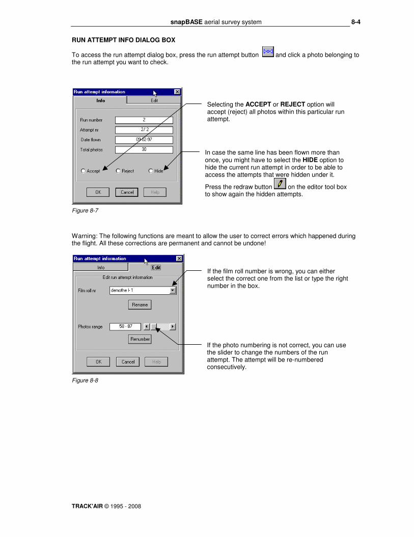
RUN ATTEMPT INFO DIALOG BOX
To access the run attempt dialog box, press the run attempt button and click a photo belonging to the run attempt you want to check.
Figure 8-7
Warning: The following functions are meant to allow the user to correct errors which happened during the flight. All these corrections are permanent and cannot be undone!
Figure 8-8
Selecting the ACCEPT or REJECT option will accept (reject) all photos within this particular run attempt.
In case the same line has been flown more than once, you might have to select the HIDE option to hide the current run attempt in order to be able to access the attempts that were hidden under it.
Press the redraw button on the editor tool box to show again the hidden attempts.
If the film roll number is wrong, you can either select the correct one from the list or type the right number in the box.
If the photo numbering is not correct, you can use the slider to change the numbers of the run attempt. The attempt will be re-numbered consecutively.

snapBASE aerial survey system
TRACK'AIR © 1995 - 2008
8-5
FILM INFO DIALOG BOX.
To work on the entire film, press the film roll button and click one of its photos. This will display the film dialog box.
Figure 8-9
Warning: The following functions are meant to allow the user to correct errors which happened during the flight. All these correction are permanent and cannot be undone!
Figure 8-10
Choose either the ACCEPT or REJECT option to accept of reject the entire film.
If this is required, you can give new photo numbers either starting from the beginning of the film or from the start of one of the run attempts.
Select the HIDE option to temporarily hide the current film. Press the redraw button
on the editor tool box to show again the hidden runs.
If the film roll number is wrong, you can either select the correct one from the list or type the right number in the box.

snapBASE aerial survey system
TRACK'AIR © 1995 - 2008
9-1
9 - PREPARING SUB FLIGHT PLANS
Please also refer to snapSHOT chapter 44, How to re-fly part of a run. Using the sliding ends of run markers it is possible to prepare several flight plans derived from the same original flight plan (in TRACKER, these flight plans are called sub flight plans). Note that this feature is a powerful and versatile project management tool but its usefulness might not be obvious at first sight. If you are new to computer flight planning some of the following might seem confusing and should preferably be considered once you have become more familiar with the system. THE SLIDING MARKERS
Figure 9-1
USE
The first obvious utilization is to move the markers to fly only part of a run. For example when a run has to be interrupted and restarted in flight or if only part of a run has to be completed. One can use the photo index overview to see where the photography ends and move the sliders as required. Further, In snapBASE or directly in snapSHOT it is possible to prepare several sub flight plans, save them and retrieve them when needed. This is very handy when it comes to the preparation of the daily photo missions during an ongoing project. For each mission one can easily prepare a new sub flight plan showing only the remaining photography. Other possible applications:
• Divide the project in various flight altitudes depending on the terrain height
• Exclude areas which should not be flown (lakes, prohibited photo areas, etc.)
• Distribute work between 2 or more planes flying the same project.
• Use colors to differentiate between areas of priority, etc.
In TRACKER, the traditional arrows or triangles used to mark the start and finish of the runs can be moved along the run from one spot to another. This allows you to change the camera on and camera off locations at your convenience, even during the flight. To do this,
press the marker button , pick a marker around the tip of the triangle and drag it along the run with the mouse. When you release the mouse button, the marker will snap to the nearest photo position and remain there. From now on, only the part of the run that is between the markers is active.

snapBASE aerial survey system
TRACK'AIR © 1995 - 2008
9-2
PROCEDURE
The easiest way to learn how to use the markers is to experiment with them. Feel free to move, show, hide, save and load as many sub plans as need be. Whatever you do has no effect on the original flight plan. Most sub planning functions are grouped in the SUB PLANNING menu.
Figure 9-2
To operate on the markers, click the marker button and click the right mouse button on the run to be edited. The sub plan pop up menu will be displayed:
Figure 9-3
Click this menu to reset the defaults.
A run segment can be divided into 3 sections. Each section has a color, blue, red or black (default blue). if you need to split a run into 2 legs, show the red markers, if you need 3 legs, show also the black markers.
Use these menus to bring the markers back to the actual ends of the runs.
Use these to save, load and delete the sub flight plans that you have prepared.
Click here to hide the selected leg (one leg must remain visible).
Use these to control the layering of the legs.
Use these to control which markers are visible.

snapBASE aerial survey system
TRACK'AIR © 1995 - 2008
9-3
EXAMPLE
The following exercise demonstrates how to use the sliding markers to prepare an alternative sub flight plan. In this case a block of photography covers a military training area which the crew might not be allowed to fly when the area is active. If this is the case, then the crew will select the sub plan to avoid flying into the area. During the digitizing, the operator has taken care to draw the outline of the military area. This line will be used to position the markers.
Figure 9-4
Figure 9-5
Figure 9-6
Figure 9-7
1) First move the blue markers so as to cover the Western part of the runs.
3) Now move the red markers so as to cover the Eastern part of the runs.
2) In the SUB PLANNING menu, click the SHOW RED MARKERS menu.

snapBASE aerial survey system
TRACK'AIR © 1995 - 2008
10-1
10 - SAVING THE TERRAIN HEIGHT
Common to snapBASE, snapSHOT, snapPLAN. It is possible to save the average ground height for each run. If this is done, the required flying altitude will be displayed in snapSHOT each time a run is selected.
• In snapBASE press the altitude button to show the altitude dialog box.
• In snapPLAN and snapSHOT select the TERRAIN HEIGHT menu from the TOOLS menu
Figure 10-1
Note: To speed up you can skip typing the heights if they are identical to the last height you typed. In this case the previous height is automatically taken. 1=1200 2=1300 3=1500 4= 5= 6= 7=1200 8=800
2) Type the reference ground height (average height) in the text box.
1) Select the unit.
Runs 4,5 and 6 will get 1500.
snapBASE aerial survey system
TRACK'AIR © 1995 - 2008
11-1
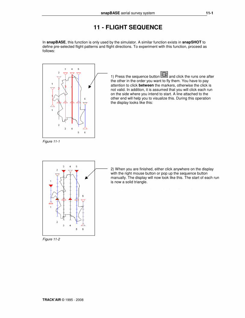
11 - FLIGHT SEQUENCE
In snapBASE, this function is only used by the simulator. A similar function exists in snapSHOT to define pre-selected flight patterns and flight directions. To experiment with this function, proceed as follows:
Figure 11-1
Figure 11-2
1) Press the sequence button and click the runs one after the other in the order you want to fly them. You have to pay attention to click between the markers, otherwise the click is not valid. In addition, it is assumed that you will click each run on the side where you intend to start. A line attached to the other end will help you to visualize this. During this operation the display looks like this:
2) When you are finished, either click anywhere on the display with the right mouse button or pop up the sequence button manually. The display will now look like this. The start of each run is now a solid triangle. In futur release, saving a sub-plan will save the sequence you

snapBASE aerial survey system
TRACK'AIR © 1995 - 2008
12-1
12 - RUN ATTEMPT SIMULATOR
To facilitate the evaluation of the system, it is possible to simulate a photo mission by using the run attempt simulation. The result of this procedure will be similar to a real photo flight. To proceed with the simulation, please follow these steps:
QUICK FLIGHT
After loading your project, selecting the FILE | RUN SIMULATOR menu will generate a small flight covering approximately half of the area.
This dialog box will be shown:
Figure 12-1
Enter any prefix you would like the simulator to use to
create the film roll numbers. For example: demo
You can either enter how many photos you want on each roll (to simulate a large project with many films) or simply check the New film roll for each run option box (not very realistic but handy).
Additionally you may choose to check the Simulate manual overlap option box if you want to simulate a flight made in manual overlap mode (the default is pinpoint automatic camera triggering).
Press OK to carry out the simulation.

snapBASE aerial survey system
TRACK'AIR © 1995 - 2008
12-2
"REAL" MISSION
This is a somewhat more complicated approach that allows to generate more realistic photo coverage.
Figure 12-2
Figure 12-3
Then select the FILE | RUN SIMULATOR to generate the flight.
Press the end of run markers button and move the markers to cover the area that you want to have flown. In our example, the markers were moved so that only the Northern part of the area will be flown.
Press the sequence button and click the runs one after the other in the order you want to fly them. You have to pay attention to click between the markers, otherwise the click is not valid. In addition, it is assumed that you will click each run on the side where you intend to start. A line will help you to visualize this.
When you are finished, either click anywhere on the display with
the RIGHT mouse button or pop up the sequence button manually. The display will now look like this. The start of each run is now a solid triangle.

snapBASE aerial survey system
TRACK'AIR © 1995 - 2008
13-1
13 - USING QUERIES
By definition a query is a question to the database. With powerful relational database such as Access used by TRACKER, queries can be very complex. A few simple queries are already available in the
TOOLS | QUERIES menu. In the future TRACKER will be equipped with a custom query generator which will allow you to find just about anything you want from your database. Selecting the TOOLS | QUERIES menu will display this dialog:
Figure 13-1
To display which photos have been rejected, select one or more rejection flags and press Apply.
Use this tab to see which flags have been set during the photo flight and display them.

snapBASE aerial survey system
TRACK'AIR © 1995 - 2008
14-1
14 - DATA MANAGEMENT
common to all Tracker modules.
OVERVIEW
Tracker uses a database system to preserve and manage all the data generated during the operation of the system. The file which contains all your data is an ACCESS database named TRACKER.MDB which is kept in the TRACKER \ MDB directory (folder). All TRACKER modules share this database. Without this database, the system cannot work. Each time a module is opened, a backup of the database is automatically created. This is a copy of the current database that can be used to recover the system should this become necessary.
Please note that if you do not use an external backup system (you certainly should), you should at least backup the TRACKER.MDB file to a floppy. Failing to do so exposes you to a possible total loss of data in the event of a hard disk failure (it happens!).
In case TRACKER is operated across several PC’s, it is important that you decide where your MAIN DATABASE is going to be located. You can benefit most from the database system if you keep one primary database regularly updated with the current data from the other PC’s. Otherwise the data will be scattered amongst several computers and you will be unable to extract profitable information from the database management system. TRACKER has a set of built-in functions that facilitate data exchange between the primary database and the others. Once the main database PC is chosen, it is advisable for a large organization to name a database supervisor who will be in charge of the database maintenance and updating. The main aspects of the database administration are:
• If the planning is prepared on an office PC, it is necessary to transfer the flight plan to the portable computers used in the aircraft.
• After a flight or as soon as this is possible, it is indispensable to update the main TRACKER database with the data generated during the flights. This is particularly critical if several airplanes are involved.
To sum up, all TRACKER modules are linked together by a common database named TRACKER.MDB. All data generated by any of these programs are automatically saved to this database and immediately available to the others. In case the planning is not directly done on the portable computer, the flight plans have to be transferred before the flight from the main PC. After the flight, the project and its new flight information have to be copied from the portable PC database back to the main TRACKER database.

snapBASE aerial survey system
TRACK'AIR © 1995 - 2008
15-1
15 - EXPORT PROCEDURE
common to snapBASE and snapSHOT.
Start the program or return to the main menu then select the Export a project or flight plan? option.
Figure 15-1
Figure 15-2
You can either select to export one project with all or part of its flight plans…
…or you can select to export several projects with all their flight plans.
Check this box if you wish to name of the export file yourself.
Check this box if you wish to export all the selected files into a single MDB file (5 projects maximum)

snapBASE aerial survey system
TRACK'AIR © 1995 - 2008
15-2
If you exported a single file then you will be asked if you want to copy it directly to a floppy disk.
Figure 15-3
Else if you exported several projects you will be informed that the files have been exported to the TRACKER/EXPORT folder.
Figure 15-4
Press YES if you want to copy your file to a floppy.

snapBASE aerial survey system
TRACK'AIR © 1995 - 2008
16-1
16 - IMPORT PROCEDURE
common to snapBASE and snapSHOT. Start the program or return to the main menu then select the Import or update projects or flight plans? option.
Figure 16-1
Open the combo box and select the a: drive if the flight plan is on a floppy. Otherwise, the file to be imported should always be in the TRACKER/IMPORT folder.
Highlight the projects to be imported.

snapBASE aerial survey system
TRACK'AIR © 1995 - 2008
17-1
17 - ARCHIVING
common to snapBASE and snapSHOT. Archiving is the process of copying part of the database to a backup file. In order to speed up data access a project that has been archived can be removed from the main database. A project that has been archived can be loaded back into the database or sent to another Tracker user.
Remark: All archived projects are saved to the TRACKER/ARCHIVES folder. Start the program or return to the main menu then select the Archive or remove projects? option.
Figure 17-1
Figure 17-2
IMPORTING AN ARCHIVED PROJECT
Start the program or return to the main menu then select the Import an archived project? option.
Figure 17-3
Select the project(s) to be archived.
Select the project to be imported and click OK. To be imported, archived projects have to be located either in the TRACKER/ARCHIVES folder or on a floppy disk.
Select this option if you want to remove the project data from the database once it has been archived.
Press YES if you want to transfer the archive file to a floppy.

snapBASE aerial survey system
TRACK'AIR © 1995 - 2008
18-1
18 - MENUS
FILE MENU
Figure 18-1
LOAD BACKGROUND FILES
Selecting the load background file menu will display this form:
Figure 18-2
Return to main menu. Select this option to return to the main menu without leaving the program.
Load background files. Select this option to load a background file.
Select here the project in which the background was saved. A backgrounds can be selected from any project and displayed with a flight plan from an other project. It is therefore possible to re-use graphics from different projects or to keep a library of valuable graphical information (restricted airspace, international borders, etc.). Remark: A background is only displayed if it covers the project area currently in use.
Select here the name of the background.

snapBASE aerial survey system
TRACK'AIR © 1995 - 2008
18-2
DATABASE MENU
Figure 18-3
DATABASE MAINTENANCE
Figure 18-4
Warning: The following functions allow you to correct errors which happened during the flight. All changes are permanent and cannot be undone. There is no record of the modification kept in the database.
RENAME SOMETHING IN THE DATABASE
Figure 18-5
Warning: The following functions allow you to correct errors which happened during the flight. All changes are permanent and cannot be undone. There is no record of the modification kept in the database.
1. To rename, select either the project, area limit, flight plan or background file to be renamed.
2. Type new name.
3. Type new number.
4. Press rename,
Use this function if you encounter problems with loading and/or processing data. Problems with the database can be caused by abnormal program operation (power failure, etc.).
Backup database. Automatically create a backup of your database in the directory TRACKER\MDB\USERBACK\... Warning: It is the responsibility of the user to delete his old backups.
Check current database version number.
Use regularly this function to compress your database, thus decreasing its size and improving access speed.

snapBASE aerial survey system
TRACK'AIR © 1995 - 2008
18-3
DELETE SOMETHING IN THE DATABASE
Figure 18-6
Select the project, flight plan, area or background you want to delete and press the delete button. Warning: Items are permanently deleted and cannot be restored!

snapBASE aerial survey system
TRACK'AIR © 1995 - 2008
18-4
CONFIG MENU
Figure 18-7
Figure 18-8
HIDE MENU
Selecting one of the entries will hide or show the corresponding drawing. This might be necessary when a large drawing is cluttering the display and slowing down the drawing functions.
Figure 18-9
SUB PLANNING MENU
Refer to the topic PREPARING SUB FLIGHT PLANS.
EXPORT MENU
Figure 18-10
Use this function to export the current flight plan to snapshot.
Reject flags: During the film inspection, it might be necessary to reject some photography. Use this menu to prepare in advance a list of common causes for rejection.
1) To add a new entry, type the text in this box add press the add button to add the new entry to the list and save it.
3) To remove an entry from the list, highlight it then press this button.

snapBASE aerial survey system
TRACK'AIR © 1995 - 2008
18-5
TOOLS MENU
Figure 18-11
Warning: The following functions allow you to correct errors which happened during the flight. All changes are permanent and cannot be undone. There is no record of the modification kept in the database.
RENAME FILM ROLL NUMBERS MENU
Figure 18-12
1). Select the film to be renamed.
Run photo simulator. Select this menu to start the photo simulator. Please refer to the topic PHOTO SIMULATOR in this manual for more details.
2). Enter its new name.
Statistics. Select this option to display a window showing some useful information about the status of the current flight plan (see below)
3). Press the Rename button.
Delete all simulated photos. Press to remove the simulated photos contained in the flight plan. Actual photos are not removed.
Queries: Use to create colored overview displaying various information (flags, cause for rejection, etc.) See the Queries topic for more details.
Use this function to correct film rolls numbers (see below).
Enter terrain height. Use this function to keep a record of the terrain height for each run.

snapBASE aerial survey system
TRACK'AIR © 1995 - 2008
18-6
STATISTICS MENU
This function displays the following dialog.
Figure 18-13

snapBASE aerial survey system
TRACK'AIR © 1995 - 2008
19-1
19 - REPORTS MENU
CREATE ACTUAL PHOTO POSITIONS REPORT
This function creates a list of all the actual photo positions: For example: Project number: oo1
Project name: airports
Run number: 1
Run attempt no: 1 Date: 4/6/97
4537 E 313701 N 379592
4537 054.65165 -006.23922
4538 E 313913 N 379695
4538 054.65252 -006.23590
4539 E 314118 N 379794
4539 054.65337 -006.23268
4540 E 314326 N 379895
4540 054.65423 -006.22942
4541 E 314533 N 379996
4541 054.65509 -006.22618
4542 E 314739 N 380095
4542 054.65593 -006.22295
Run attempt no: 2 Date: 4/6/97
4580 E 316592 N 381002
4580 054.66365 -006.19389
4581 E 316390 N 380903
4581 054.66281 -006.19706
4582 E 316182 N 380804
4582 054.66197 -006.20032
4583 E 315976 N 380704
4583 054.66111 -006.20355

snapBASE aerial survey system
TRACK'AIR © 1995 - 2008
19-2
CREATE ACTUAL GPS PHOTO POSITION REPORT
This function creates a report using the data recorded in flight from the GPS.
CREATE PLANNED PHOTO POSITIONS REPORT
This function creates a list of all the planned photo positions: Project number: oo1 Project name: airports Run number: 1 1 N 54.6517 W 006.2392 2 N 54.6525 W 006.2360 3 N 54.6534 W 006.2327 4 N 54.6543 W 006.2295 5 N 54.6551 W 006.2262 6 N 54.6560 W 006.2230 7 N 54.6568 W 006.2197 8 N 54.6577 W 006.2165 9 N 54.6585 W 006.2133 10 N 54.6594 W 006.2100 11 N 54.6602 W 006.2068 12 N 54.6611 W 006.2035 13 N 54.6619 W 006.2003 14 N 54.6628 W 006.1970 15 N 54.6637 W 006.1938 Run number: 2 16 N 54.6479 W 006.2372 17 N 54.6487 W 006.2340 18 N 54.6496 W 006.2307 19 N 54.6504 W 006.2275 20 N 54.6513 W 006.2242 21 N 54.6522 W 006.2210 22 N 54.6530 W 006.2177 23 N 54.6539 W 006.2145 24 N 54.6547 W 006.2113 25 N 54.6556 W 006.2080 26 N 54.6564 W 006.2048

snapBASE aerial survey system
TRACK'AIR © 1995 - 2008
19-3
CREATE A PRINTING LIST (LIST OF ACCEPTED PHOTOGRAPHY).
This function creates a list of accepted photography, which can be sent to the lab.
Figure 19-1
For example: Printing list
Project name: Koeln
Project number: 1
Flight plan name: 4000
Date: 10-02-97
Film number: film 2
Run 1 152 - 157
Run 2 158 - 164
Run 3 165 - 181
Run 4 182 - 188
Run 4 189 - 191
Run 5 192 - 222
Run 6 223 - 252
Run 7 253 - 282
Run 8 283 - 312
Run 9 313 - 342
Run 10 343 - 374
Run 11 375 - 404
RUN 1 405 - 410
1. Select the film roll.
2. Select save to disk and/or print.
3. Press apply.
snapBASE aerial survey system
TRACK'AIR © 1995 - 2008
19-4
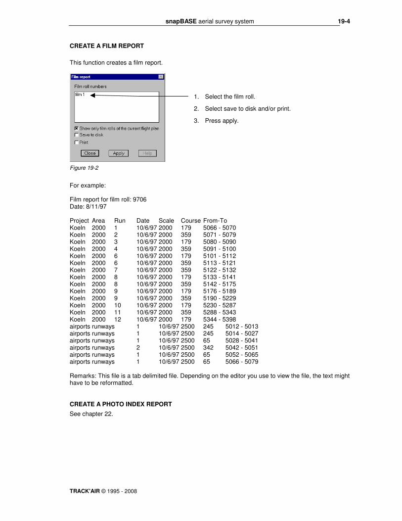
CREATE A FILM REPORT
This function creates a film report.
Figure 19-2
For example: Film report for film roll: 9706 Date: 8/11/97 Project Area Run Date Scale Course From-To Koeln 2000 1 10/6/97 2000 179 5066 - 5070 Koeln 2000 2 10/6/97 2000 359 5071 - 5079 Koeln 2000 3 10/6/97 2000 179 5080 - 5090 Koeln 2000 4 10/6/97 2000 359 5091 - 5100 Koeln 2000 6 10/6/97 2000 179 5101 - 5112 Koeln 2000 6 10/6/97 2000 359 5113 - 5121 Koeln 2000 7 10/6/97 2000 359 5122 - 5132 Koeln 2000 8 10/6/97 2000 179 5133 - 5141 Koeln 2000 8 10/6/97 2000 359 5142 - 5175 Koeln 2000 9 10/6/97 2000 179 5176 - 5189 Koeln 2000 9 10/6/97 2000 359 5190 - 5229 Koeln 2000 10 10/6/97 2000 179 5230 - 5287 Koeln 2000 11 10/6/97 2000 359 5288 - 5343 Koeln 2000 12 10/6/97 2000 179 5344 - 5398 airports runways 1 10/6/97 2500 245 5012 - 5013 airports runways 1 10/6/97 2500 245 5014 - 5027 airports runways 1 10/6/97 2500 65 5028 - 5041 airports runways 2 10/6/97 2500 342 5042 - 5051 airports runways 1 10/6/97 2500 65 5052 - 5065 airports runways 1 10/6/97 2500 65 5066 - 5079 Remarks: This file is a tab delimited file. Depending on the editor you use to view the file, the text might have to be reformatted. CREATE A PHOTO INDEX REPORT
See chapter 22.
1. Select the film roll.
2. Select save to disk and/or print.
3. Press apply.

snapBASE aerial survey system
TRACK'AIR © 1995 - 2008
20-1
20 - CAPTURE MENU
(This feature is not required for normal operation)
Figure 20-1
Select this menu to save the current display as a Windows metafile. A metafile is a Windows graphic file that can easily be imported into other applications. metafile can be scaled but cannot easily be edited.
Select this menu to place on the clipboard a copy of the current display in the Windows metafile format. A metafile is a Windows graphic file that can easily be imported into other applications. Metafiles can be scaled but cannot easily be edited.
Select this menu to save the current display as a Windows bitmap. A bitmap is a Windows graphic file that can easily be imported into other applications. Bitmaps do not scale very well but can be easily edited in a bitmap editor such as Paintbrush.
Select this menu to place on the clipboard a copy of the current display in the Windows bitmap format. A bitmap is a Windows graphic file that can easily be imported into other applications. Bitmaps do not scale very well but can easily be edited in a bitmap editor such as Paintbrush..

snapBASE aerial survey system
TRACK'AIR © 1995 - 2008
21-1
21 - OPTION : FILM ANNOTATION
The Tracker system supports film margin annotation for the Leica RC30 and Zeiss TOP. OVERVIEW
The system was designed to provide maximum flexibility and ease of use:
• There is no special action to be taken to print the margin on the film, the system automatically communicates with the camera and instructs it to print the margin text.
• The text of the margin can contain plain text as well as data fields that are linked to the database. The value of these fields is automatically filled by the system.
• Different margin layouts can be prepared in advance with the help of the margin editor and selected at will before or during the flight.
• A standard default margin can be prepared once and for all. snapSHOT will automatically use the default margin if no other choice was made.
• All the variable parameters such as project name, time, run numbers, altitude, positions, etc, are automatically updated by snapSHOT when necessary.
HOW DO THE MARGINS WORK?
snapSHOT stores margin as a sort of template that uses a combination of plain text and place holders for the variable data (time, run numbers, altitude, etc). The user types the plain text and the place holders are automatically filled by snapSHOT. For
example, if you want to display the latitude, snapSHOT will automatically replace the latitude place holder NNNNNNNN by the actual value of the latitude. The margin is prepared by picking blocks of information from a list in the order you want them to appear on the film. Each information block contains an optional caption (plain text) and a data field (place holder) which is automatically filled by snapSHOT. For example: GPS time GGGGGGGG will be replaced by: GPS time 13:03:24
Figure 21-1
Figure 21-2
Template containing a set of data fields.
Text of the margin as it will be printed on the film.

snapBASE aerial survey system
TRACK'AIR © 1995 - 2008
21-2
WHERE TO PREPARE THE MARGINS?
The margins can be prepared indifferently in snapBASE or in snapSHOT. In case the margin is prepared on a different computer than the one used during the mission, the margin will be automatically transferred along with the flight plan. The selected margin will be also automatically loaded and displayed in the camera. This allows the text of the margins to be prepared in advance in the office. DEFINITION OF DATA FIELDS
The data fields are place holders (or templates) which are used by snapSHOT to recognize where the data has to be written. A data field is represented by one character repeated several times (HHHHHH). There are 2 types of data fields: Fixed length, such as the date or time. Variable length, such as the project name or film roll number. The characters representing the variable length data fields are preceded by a @. If you modify a data field in the editing window, it will loose its link to the database and will not work anymore. DEFINITION OF FIELDS CAPTIONS
The data field caption is the title which proceeds the data, E.G. JOB, TIME, FILM, etc. You may edit the captions in the data fields caption panel. You can change the wording, the language or simply remove a caption that you do not want to display. The captions are stored in the database and are the same for all projects. DEFINITION OF FREE FIELDS
Free fields are simply small strings of text which you can save to avoid retyping, E.G. Copyright TRACK'AIR BEHAVIOR OF THE MARGIN
• There can be only one margin saved with each flight plan.
• If no margin has been saved then the system will automatically use the default margin.
• To disable sending the margin, deselect Tracker sends data to right margin on the EDI configuration panel.

snapBASE aerial survey system
TRACK'AIR © 1995 - 2008
21-3
PREPARING A NEW MARGIN.
Figure 21-3
The margin editor will be displayed. It has 4 panels: Prepare new margins, Data fields’ captions, Free fields, and EDI configuration. Select the first panel Prepare new margins that is used to prepare, save and load the margin layouts.
Figure 21-4
Test margin: The layout is displayed in the editor window. Press the button to see the actual text of the margin in the preview window.
Select the Annotation menu. Select your model of camera. Select the Set margins menu.
Undo last: Remove the last entry.
Clear margin: Clear the editor window.
Load/Delete Margin: Press to display the list of margin templates that you have saved.
Preview window: Show the text of the margin as it will be displayed.
Editor window: You can use this window as a normal text editor and type directly in it or you can paste fields from the lists or combine both actions. If you paste a data field, do not alter the actual data template, e.g. GGGGGGGG, which is used by the program to recognize the type of information that has to be printed. You may change or remove all other text information (see also the configuration window later in this chapter).
Apply: Save the current margin with the flight plan
Max 100 characters: In the case of the RC30, this is the maximum number of characters accepted by the camera.

snapBASE aerial survey system
TRACK'AIR © 1995 - 2008
21-4
If this is the first time that the margin is used, snapSHOT will display a default margin in the text editor: For example: Area @EEEEE Date DDDDDDDD GPS GGGGGGGG Lat NNNNNNNN Lon EEEEEEEEE Run RRR The @ characters represent variable length text, in this case the name of the area. The DDD, etc. represent fixed length text, such as the time or the date.
SAMPLE MARGIN
To create a new margin layout, clear the editor window. Follow this example: First pick the Roll number in the data field list. The editor window will show: Roll @AAAA Add the run number: Roll @AAAA Run RRR Add the Job name: Roll @AAAA Run RRR Job @DDDDDDDD Add the time, lat, long, etc. Roll @AAAA Run RRR Job @DDDDDDDD GPS GGGGGGGG Roll @AAAA Run RRR Job @DDDDDDDD GPS GGGGGGGG Lat NNNNNNNN Lon EEEEEEEEE At any stage you can press the Test button to see the actual text:
Figure 21-5
Once the margin is complete, press the apply button to make this margin the active one. You will be prompted to save the margin for later use:
Figure 21-6
Figure 21-7
Type a name and press OK. Note that if you give the name default to a margin, then it will be automatically loaded if no other margin is selected.
This margin is now active and saved with the current flight plan. Press YES if you want to save this margin layout for later use.

snapBASE aerial survey system
TRACK'AIR © 1995 - 2008
21-5
DATA FIELDS CAPTIONS PANEL
Figure 21-8
FREE FIELDS PANEL
Figure 21-9
Free fields. This is a simple text editor. Place on each line a block of text that you might use at a later stage to prepare a margin.
It is possible to change the titles that are automatically displayed in front of the data field. You can change the text, the language or remove the titles.
Undo Last: Undo the last action.
Reset initial state: Undo all changes made.
Apply: Save the changes.
Total Reset: Return to the original default of TRACKER (English).

snapBASE aerial survey system
TRACK'AIR © 1995 - 2008
21-6
EDI CONFIGURATION PANEL (RC30 ONLY)
To configure the way the program interacts with the camera, select the last panel.
Figure 21-10
CABLES CONNECTIONS (RC30)
Figure 21-11
Tracker sends data to the right margin: When this check box is marked, Tracker will send the margin to the camera. This is the default, do not change other than for testing purpose.
Camera sends Margin data after each exposure: When checked, the RC30 will send data after each exposure. This is the default, do not change other than for testing purpose.
Camera prints internal data to the left margin: When checked, the RC30 will print
its internal data to the left margin.
Camera sends line feed: When checked, the RC30 will send a line feed character after each line. This is the default, do not change other than for testing purpose.
Pin H
Pin R
Pin HH
Pin J
Pin M
Pin L
Pin Y
TX out
RX in
CTS in
RTS out
Trigger
Ground
Mid point

snapBASE aerial survey system
TRACK'AIR © 1995 - 2008
22-1
22 - PHOTO INDEX MENU
This function allows you to create customs reports using the standard comma delimited file format, which can easily be imported in any word processor or spreadsheet for further editing and formatting.
INDEX (TAB1)
LOAD SAVE DELETE LAYOUT
Select film roll numbers Select here the rolls, which have to be included in the report.
Checking status If you want to distinguish photos which have been accepted, rejected or which are new, you can type a symbol, which will be printed in front of the photo number. For example, A for Accepted, R for Rejected and N for Not yet checked.
Coordinate formats This is the format which will be used to print the geographical coordinates. For example: DD MM SS.sss = 125 05 56.123 DD MM.mmmmm = 125 05.30234 DD.dddddddd = 125.3657789
Load/save/delete layout You can prepare different layouts, save and retrieve them when required. Pressing this button will display the following dialog box:
Photo index layouts names This is the list of the previously saved layouts. To load a layout, select it then hit the Load button. To delete a layout, select it then hit the Delete button.
Type new Name To give a name and save the current layout, type the new name, then hit the save button.

snapBASE aerial survey system
TRACK'AIR © 1995 - 2008
22-2
FIELDS TO BE INCLUDED (TAB 2)
EDIT FIELD NAMES (TAB 3)
Fields not selected This list displays the items which are available in the database and which can be displayed in the report. To add some of the fields, select them then hit the => button
Selected fields This second list displays the items, which have been select in the report. To change the order, in which the field will be presented, select an item and use the UP or DOWN button to change its place in the list.
Default field names This list displays the default field name used by the Tracker software.
User field names If you wish to change the way the title fields appears in the report (language, etc.), type in this list the new word or spelling. Use the Reset button to restore the English default.

snapBASE aerial survey system
TRACK'AIR © 1995 - 2008
22-3
FORMAT (TAB 4)
ANTENNA (TAB 5)
Time Select the format used to display the times, hh:mm:ss.ss, hours, minutes and seconds or ssssss.ssss seconds since Sunday midnight (GPS time). Local Time = GMT + Enter here the offset between local time and GMT (UTC) time recorded by the GPS
Scale If you wish to display the photo scale with a 1: (as in 1:25,000), then select this option.
Compute local height from GPS height. By default, Tracker displays the WGS84 height. If you know the difference between the local height and the WGS height, you can enter the value here.
GPS antenna offset (correction is applied only to local coordinates). FOR AUSTRALIA ONLY Enter here the offset between the GPS antenna phase center and the camera projection center. These values should be accurately surveyed. By convention, the X offset represents the lateral offset (across the aircraft axis) between the camera and the antenna. If one looks towards the front of the airplane, the offset is positive if the camera is left of the antenna, negative if the camera is right of the antenna. By convention, the Y offset represents the longitudinal offset (along the aircraft axis) between the antenna and the GPS. If one looks towards the front of the airplane, the offset is positive if the camera is to the rear of the antenna, negative if the camera is to the front of the antenna. The Z offset is the vertical separation between the plan of the projection center and the plan of the antenna. Apply offset to GPS positions: Select this option to activate the correction. Save: Hit the save button to save these parameters.
Altitudes Select here the unit used to display the altitude, feet or meters. Save: Hit the save button to save these parameters.

snapBASE aerial survey system
TRACK'AIR © 1995 - 2008
23-4
23 - NOTES