the uk standards for roundabouts and mini roundabouts · the uk standards for roundabouts and...
TRANSCRIPT
THE UK STANDARDS FOR ROUNDABOUTS AND MINI-ROUNDABOUTS Janet V Kennedy Transport Research Laboratory (TRL) Crowthorne House Nine Mile Ride Wokingham Berkshire RG40 3GA United Kingdom Tel +44 (0) 1344 770953 Email [email protected]
ABSTRACT
The modern priority rule for roundabouts was first introduced in the UK during the 1960s and has been in widespread use ever since, gradually being adopted around the world. Roundabouts are recognised as a safe and efficient form of junction, particularly where side road flows are high. Extensive research led to predictive models for both safety and capacity and modern design is based on these relationships.
The idea of mini-roundabouts was conceived during the 1970s. They are used in the UK in urban areas where a roundabout would be the first choice of junction if space permitted. They usually replace existing priority junctions. Like conventional roundabouts, they are seen as a safe and efficient form of junction. Both capacity and accident predictive relationships have been developed specifically for mini-roundabouts.
The new standards for the geometric design of roundabouts and mini-roundabouts were published in 2007. Details of both standards are given in the paper.
BACKGROUND
The modern priority rule for roundabouts was first introduced in the UK during the 1960s and has been in widespread use ever since, gradually being adopted around the world. Roundabouts are recognised as a safe and efficient form of junction, particularly where side road flows are high. Extensive research led to predictive models for both safety and capacity and modern design is based on these relationships. A revised standard for geometric design of roundabouts was published in August 2007.
The idea of mini-roundabouts was conceived during the 1970s. They are used in the UK in urban areas where a roundabout would be the first choice of junction if space permitted. They usually replace existing priority junctions. Both capacity and accident predictive relationships have been developed specifically for mini-roundabouts. Historically the design standard for roundabouts also covered mini-roundabouts. A new standard specifically for mini-roundabouts was published at the same time as the revised roundabout standard in 2007.
UK STANDARDS FOR ROADS
In the UK, standards for roads may be found in the Design Manual for Roads and Bridges (DMRB). The website is:
www.standardsforhighways.co.uk/dmrb/index.htm The DMRB contains around 400 different standards and advice notes relating to all
aspects of road and bridge design. The amount of guidance varies between standards. For roundabouts, it would be essential to consult other documents.
The DMRB applies to the design of trunk roads i.e. major roads (including motorways) that are operated by the Highways Agency in England and the Overseeing Organisations in Wales, Scotland and Northern Ireland. It represents good UK practice and is
National Roundabout Conference 2008 1 Transportation Research Board
therefore used on all roads where possible. However on local authority roads, cost-benefit may become the dominant criterion.
Some parts of a standard are mandatory for trunk roads whilst the remainder simply represent good practice. Where it is not possible to follow the mandatory clauses for a trunk road, the designer must decide whether s/he can re-design the road or whether to seek a “Departure from Standard” from the appropriate Overseeing Organisation. A departure would be granted in cases where the risk was deemed to be relatively low and the cost of compliance very high. In some cases, mitigation measures such as reducing the speed limit might be required to reduce the risk.
ROUNDABOUT AND MINI-ROUNDABOUT STANDARDS IN THE UK
There are a number of different standards relating directly to roundabouts, specifically:
TD 16/07 Geometric design of roundabouts TD 78/97 Design of road markings at roundabouts TD 51/03 Segregated left turn lanes and subsidiary deflection islands at
roundabouts TD 50/04 The geometric layout of signal controlled junctions and signalised
roundabouts TA 86/03 Layout of large signal controlled junctions TD 54/07 Design of mini-roundabouts
Note that the last two digits at the end of the standard number represent the year of publication. Another very relevant standard is:
HD 19/03 Safety audit since a safety audit must be undertaken at several stages during planning and construction of a roundabout and also once it has been in operation for some time.
The main UK standard for roundabout design, TD 16, has recently been updated. The title “Geometric design of roundabouts” represents the importance in the UK attached to geometric design in order to maximise capacity and safety at roundabouts for minimum cost. TD 16, TD 78 and TD 51 deal with the design of Compact, Normal and Grade Separated Roundabouts, whilst TD 50 and TA 86 cover Signalised Roundabouts and TD 54 is a new standard for mini-roundabouts. This paper describes the main changes in the new version of TD 16 and the contents of TD 54.
ROUNDABOUT STANDARD TD 16
The main changes in the 2007 version of TD 16 are as follows:
• Design hierarchy • Location of pedestrian crossings • New Compact Roundabout • Entry deflection • Outward sloping crossfall • Visibility to the right (left in the US) • Signing and marking • Truck rollover
The reasons for the main changes are documented in Kennedy (2007). The capacity
and safety performance of roundabouts can be addressed using suitable software such as RODEL and ARCADY.
National Roundabout Conference 2008 2 Transportation Research Board
Janet V Kennedy
New design hierarchy
The new design hierarchy is set out in Table 1. It is based on the type of road, the AADT flow and the needs of non-motorised users (pedestrians and cyclists). A total of 10 different categories are listed, which encompass Grade separated, Normal or Compact Roundabouts, but exclude Mini-roundabouts and Signalised Roundabouts.
The categories of roundabout depend on:
• road class (the highest class on any approach) • speed limit (highest within 100m on any approach). • AADT flow (highest on any approach)
From the hierarchy, the designer then considers the recommendations for cyclist and pedestrian provision at this category of roundabout depending on the levels of demand. The types of cyclist provision are:
• signal controlled crossing • informal crossing • none (that is, cyclists mix with traffic on the circulatory carriageway)
Cycle lanes on the circulatory carriageway are not recommended. The types of pedestrian provision are:
• informal crossing (dropped kerb) • zebra (uncontrolled) crossing • signal controlled crossing
On urban single carriageway roads, the levels of two-way AADT flow and non-
motorised user demand affect provision as follows:
• flows of up to 8,000 vehicles per day (vpd) allow cyclists to mix with traffic and only informal crossings are required for pedestrians
• flows between 8,000 and 12,000 vpd may require an informal or a zebra crossing for pedestrians or a combined signal controlled crossing for both pedestrians and cyclists
• flows above 12,000 vpd require a zebra crossing for pedestrians, or a signal controlled crossing for both pedestrians and cyclists
On urban dual-carriageway roads, suggested provision is as follows, depending on two-way AADT flows and pedestrian and cyclist demand:
• flows of up to 16,000 vehicles per day (vpd) may require an informal or a zebra crossing for pedestrians
• flows of 16,000 to 25,000 vpd may require either a zebra or a signalised crossing • flows exceeding 25,000 vpd may require a signalised crossing
On rural roads, if pedestrian or cycle demand warrants a crossing, it should be either signal controlled or grade separated.
It should be noted that there is generally no need to provide a formal crossing on more than one or two arms of the roundabout. If a formal crossing is required on all arms, it may be better to provide a signalised junction or roundabout.
National Roundabout Conference 2008 3 Transportation Research Board

TABLE 1: Design hierarchy: selection of roundabout type and recommended provision for non-motorised users
Roundabout type
Highest class of road on any
approach
Highest speed limit within 100m on any approach
Highest two-way AADT on any approach
Recommended cyclist provision
Recommended pedestrian provision
Combined cycle and pedestrian provision
Roundabout Type
1 Grade separated entry / exit Any Any Signal controlled /
grade separated1 Signal controlled / grade separated1
Signal controlled / grade separated1
Grade Separated
2 Dual carriageway1 >40mph Any Signal controlled / grade separated3
Signal controlled / grade separated3
Signal controlled / grade separated1 Normal
3 Single carriageway2 >40mph >8,000 Signal controlled3 Signal controlled3 Signal controlled1 Normal
4 Single carriageway2 >40mph <8,000 Cyclists mix with traffic Informal N/A Compact
5 Dual carriageway1 ≤40mph >25,000 Signal controlled Signal controlled Signal controlled Normal
6 Dual carriageway1 ≤40mph 16,000-25,000 Signal controlled Zebra4 or signal controlled Signal controlled Normal
7 Dual carriageway1 ≤40mph <16,000 Informal Informal or zebra4 Informal Normal
8 Single carriageway2 ≤40mph >12,000 Signal controlled Zebra4 Signal controlled Normal
9 Single carriageway2 ≤40mph 8,000-12,000 Informal Informal or zebra4 Informal or signal-controlled2
Normal or Compact
10 Single carriageway2 ≤40mph <8,000 Cyclists mix with traffic Informal Informal Compact
1. A dual carriageway is a divided highway
2. A single carriageway is an undivided highway
3. Signal controlled crossing to be provided only if warranted by site-specific conditions; an alternative is grade separated provision
4. Zebra crossings should not be used where the 85th percentile speed exceeds 35mph
National Roundabout Conference 2008 4 Transportation Research Board
Location of pedestrian crossings
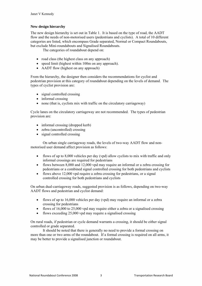
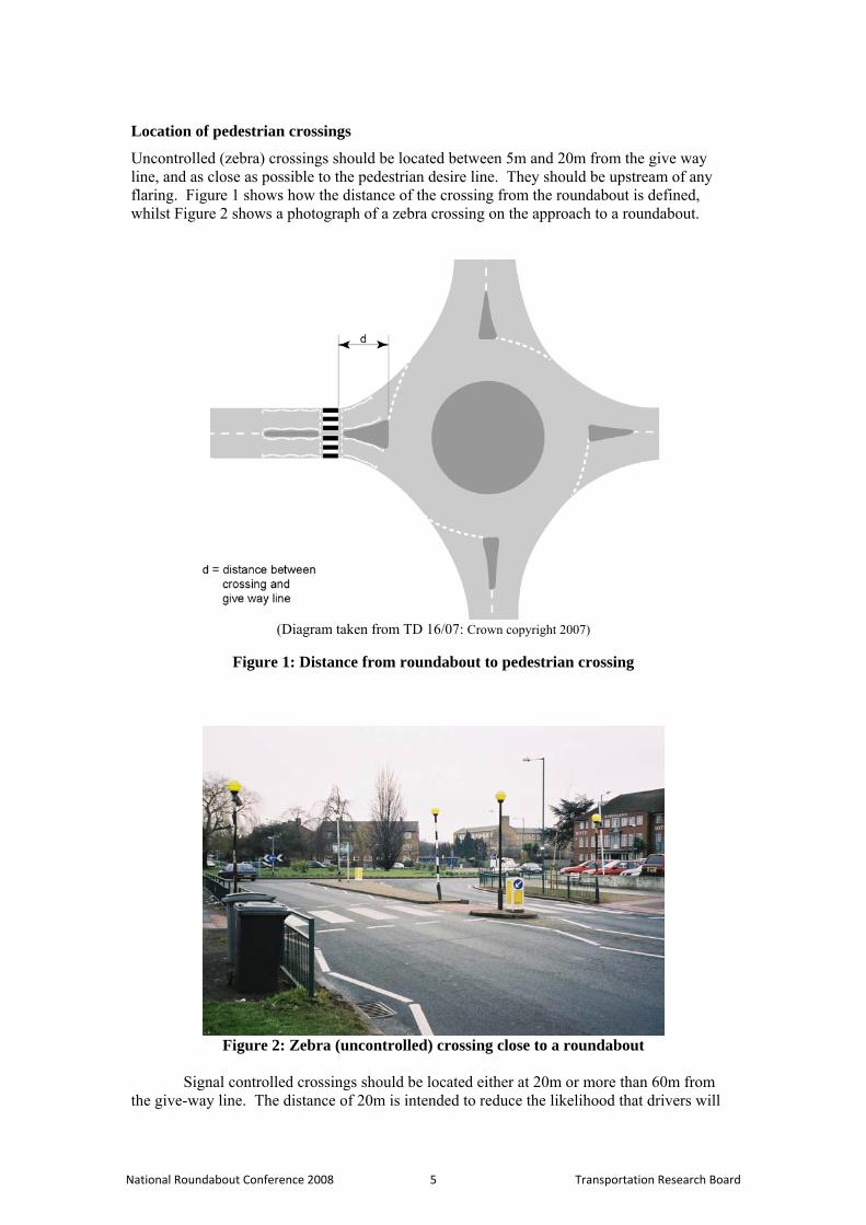
Uncontrolled (zebra) crossings should be located between 5m and 20m from the give way line, and as close as possible to the pedestrian desire line. They should be upstream of any flaring. Figure 1 shows how the distance of the crossing from the roundabout is defined, whilst Figure 2 shows a photograph of a zebra crossing on the approach to a roundabout.
(Diagram taken from TD 16/07: Crown copyright 2007)
Figure 1: Distance from roundabout to pedestrian crossing
Figure 2: Zebra (uncontrolled) crossing close to a roundabout
Signal controlled crossings should be located either at 20m or more than 60m from
the give-way line. The distance of 20m is intended to reduce the likelihood that drivers will
National Roundabout Conference 2008 5 Transportation Research Board
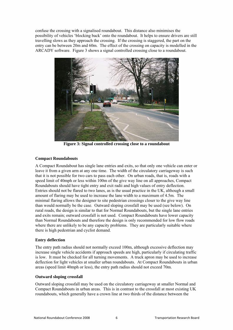
confuse the crossing with a signalised roundabout. This distance also minimises the possibility of vehicles ‘blocking back’ onto the roundabout. It helps to ensure drivers are still travelling slows as they approach the crossing. If the crossing is staggered, the part on the entry can be between 20m and 60m. The effect of the crossing on capacity is modelled in the ARCADY software. Figure 3 shows a signal controlled crossing close to a roundabout.
Figure 3: Signal controlled crossing close to a roundabout
Compact Roundabouts
A Compact Roundabout has single lane entries and exits, so that only one vehicle can enter or leave it from a given arm at any one time. The width of the circulatory carriageway is such that it is not possible for two cars to pass each other. On urban roads, that is, roads with a speed limit of 40mph or less within 100m of the give way line on all approaches, Compact Roundabouts should have tight entry and exit radii and high values of entry deflection. Entries should not be flared to two lanes, as is the usual practice in the UK, although a small amount of flaring may be used to increase the lane width to a maximum of 4.5m. The minimal flaring allows the designer to site pedestrian crossings closer to the give way line than would normally be the case. Outward sloping crossfall may be used (see below). On rural roads, the design is similar to that for Normal Roundabouts, but the single lane entries and exits remain; outward crossfall is not used. Compact Roundabouts have lower capacity than Normal Roundabouts and therefore the design is only recommended for low flow roads where there are unlikely to be any capacity problems. They are particularly suitable where there is high pedestrian and cyclist demand.
Entry deflection
The entry path radius should not normally exceed 100m, although excessive deflection may increase single vehicle accidents if approach speeds are high, particularly if circulating traffic is low. It must be checked for all turning movements. A truck apron may be used to increase deflection for light vehicles at smaller urban roundabouts. At Compact Roundabouts in urban areas (speed limit 40mph or less), the entry path radius should not exceed 70m.
Outward sloping crossfall
Outward sloping crossfall may be used on the circulatory carriageway at smaller Normal and Compact Roundabouts in urban areas. This is in contrast to the crossfall at most existing UK roundabouts, which generally have a crown line at two thirds of the distance between the
National Roundabout Conference 2008 6 Transportation Research Board
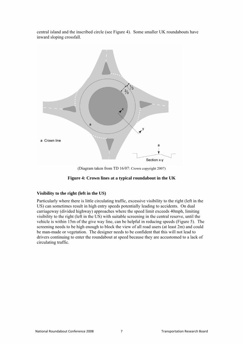
central island and the inscribed circle (see Figure 4). Some smaller UK roundabouts have inward sloping crossfall.
(Diagram taken from TD 16/07: Crown copyright 2007)
Figure 4: Crown lines at a typical roundabout in the UK
Visibility to the right (left in the US)
Particularly where there is little circulating traffic, excessive visibility to the right (left in the US) can sometimes result in high entry speeds potentially leading to accidents. On dual carriageway (divided highway) approaches where the speed limit exceeds 40mph, limiting visibility to the right (left in the US) with suitable screening in the central reserve, until the vehicle is within 15m of the give way line, can be helpful in reducing speeds (Figure 5). The screening needs to be high enough to block the view of all road users (at least 2m) and could be man-made or vegetation. The designer needs to be confident that this will not lead to drivers continuing to enter the roundabout at speed because they are accustomed to a lack of circulating traffic.
National Roundabout Conference 2008 7 Transportation Research Board
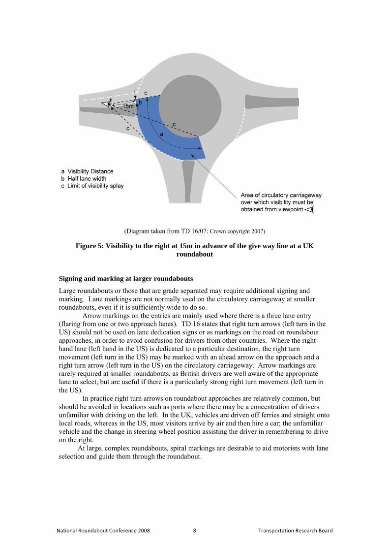
(Diagram taken from TD 16/07: Crown copyright 2007)
Figure 5: Visibility to the right at 15m in advance of the give way line at a UK roundabout
Signing and marking at larger roundabouts
Large roundabouts or those that are grade separated may require additional signing and marking. Lane markings are not normally used on the circulatory carriageway at smaller roundabouts, even if it is sufficiently wide to do so.
Arrow markings on the entries are mainly used where there is a three lane entry (flaring from one or two approach lanes). TD 16 states that right turn arrows (left turn in the US) should not be used on lane dedication signs or as markings on the road on roundabout approaches, in order to avoid confusion for drivers from other countries. Where the right hand lane (left hand in the US) is dedicated to a particular destination, the right turn movement (left turn in the US) may be marked with an ahead arrow on the approach and a right turn arrow (left turn in the US) on the circulatory carriageway. Arrow markings are rarely required at smaller roundabouts, as British drivers are well aware of the appropriate lane to select, but are useful if there is a particularly strong right turn movement (left turn in the US).
In practice right turn arrows on roundabout approaches are relatively common, but should be avoided in locations such as ports where there may be a concentration of drivers unfamiliar with driving on the left. In the UK, vehicles are driven off ferries and straight onto local roads, whereas in the US, most visitors arrive by air and then hire a car; the unfamiliar vehicle and the change in steering wheel position assisting the driver in remembering to drive on the right.
At large, complex roundabouts, spiral markings are desirable to aid motorists with lane selection and guide them through the roundabout.
National Roundabout Conference 2008 8 Transportation Research Board
Other changes to the roundabout standard TD 16
Lane widths
Lane widths on the entry to Normal Roundabouts should be between 3m and 4.5m, with 3m to 3.5m most appropriate at multi-lane entries and 4.5m at Compact Roundabouts. However, it is assumed in the UK that it is the entry width rather than the number of lanes that affects capacity. The only guidance relating to the circulatory carriageway is that the total width should be between 1 and 1.2 times the entry width (see above for details on lane markings).
Truck rollover
There are many possible causes of truck rollover at roundabouts and frequently, it will be a combination rather than a single cause, for example:
• Truck entering the roundabout too quickly (which might be due to excessive visibility and little circulating flow or to inadequate entry deflection)
• A tight turn on the circulatory carriageway (which is likely to be due to poor design or a historic layout, and is expensive to rectify)
• Reverse curves on the approach (which may be improved by introducing a transition between the two curves)
• Abrupt changes in crossfall on the circulatory carriageway or exit (if crown lines are used, they should be smoothed)
• Excessive entry deflection The effect of each of the possible causes will depend on the type of truck, its speed and the load carried; for example, there may be resonance due to carcasses of meat hanging within the truck, or to a tanker being half full, or to the suspension.
It is possible for trucks to overturn on curves whilst travelling at speeds as low as 15mph under some circumstances. Where trucks enter the roundabout too quickly, various measures can be used to mitigate risk, for example, a truck-activated sign to warn these vehicles that they are travelling too quickly or the use of suitable screening to limit visibility to the right (left in the US) until 15m before the give way line - see above. The use of reverse curves as a device to slow traffic on the approach should be avoided unless there is a straight section between the two curves.
Other possible concerns regarding rollover are the use of outward sloping crossfall (not recommended at large or rural roundabouts in the UK – see above) and truck aprons. Truck aprons are intended to be unattractive to cars, for example by being made of textured material. In the UK, they are only recommended at smaller roundabouts and are not considered necessary at larger ones; the kerb should be rounded and the slope should not be too steep. It is well accepted by British drivers that trucks will not necessarily be able to keep within their lane whilst entering and negotiating a roundabout and that they should therefore be given a wide berth.
MINI-ROUNDABOUT STANDARD TD 54
Mini-roundabouts have a central island (white circle) composed of a circular solid white road marking between 1m and 4m in diameter that is capable of being driven over. A vehicle proceeding through the junction must keep to the left of the white circle (right in the US) unless the size of the vehicle or the layout of the junction makes this impractical. Figure 6 shows a typical mini-roundabout (although note that the car shown overruns the central island).
National Roundabout Conference 2008 9 Transportation Research Board
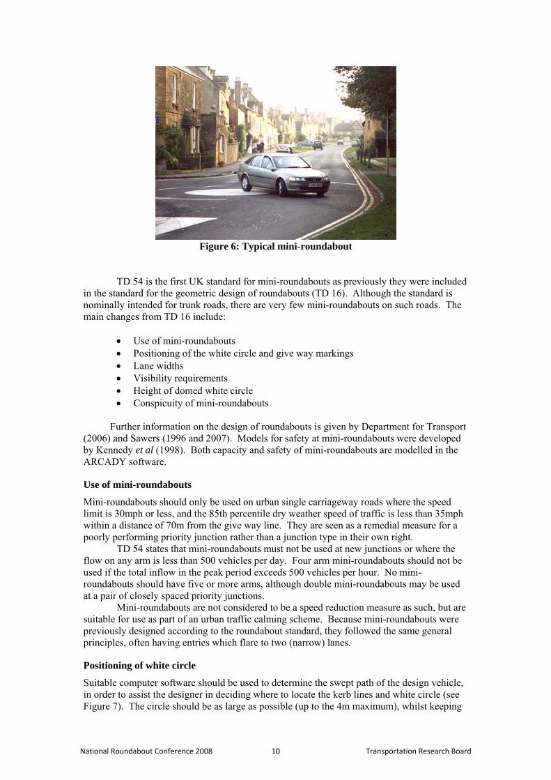
Figure 6: Typical mini-roundabout
TD 54 is the first UK standard for mini-roundabouts as previously they were included in the standard for the geometric design of roundabouts (TD 16). Although the standard is nominally intended for trunk roads, there are very few mini-roundabouts on such roads. The main changes from TD 16 include:
• Use of mini-roundabouts • Positioning of the white circle and give way markings • Lane widths • Visibility requirements • Height of domed white circle • Conspicuity of mini-roundabouts
Further information on the design of roundabouts is given by Department for Transport
(2006) and Sawers (1996 and 2007). Models for safety at mini-roundabouts were developed by Kennedy et al (1998). Both capacity and safety of mini-roundabouts are modelled in the ARCADY software.
Use of mini-roundabouts
Mini-roundabouts should only be used on urban single carriageway roads where the speed limit is 30mph or less, and the 85th percentile dry weather speed of traffic is less than 35mph within a distance of 70m from the give way line. They are seen as a remedial measure for a poorly performing priority junction rather than a junction type in their own right.
TD 54 states that mini-roundabouts must not be used at new junctions or where the flow on any arm is less than 500 vehicles per day. Four arm mini-roundabouts should not be used if the total inflow in the peak period exceeds 500 vehicles per hour. No mini-roundabouts should have five or more arms, although double mini-roundabouts may be used at a pair of closely spaced priority junctions.
Mini-roundabouts are not considered to be a speed reduction measure as such, but are suitable for use as part of an urban traffic calming scheme. Because mini-roundabouts were previously designed according to the roundabout standard, they followed the same general principles, often having entries which flare to two (narrow) lanes.
Positioning of white circle
Suitable computer software should be used to determine the swept path of the design vehicle, in order to assist the designer in deciding where to locate the kerb lines and white circle (see Figure 7). The circle should be as large as possible (up to the 4m maximum), whilst keeping
National Roundabout Conference 2008 10 Transportation Research Board
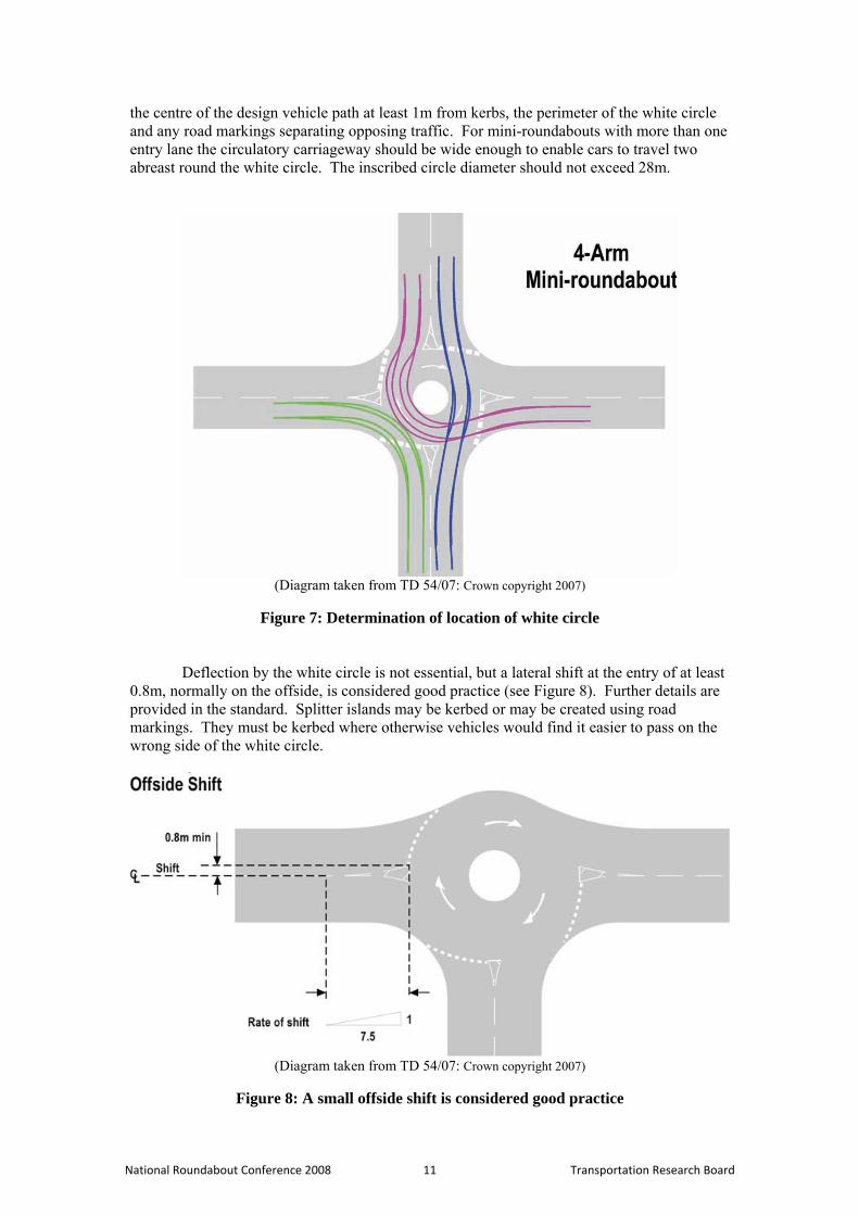
the centre of the design vehicle path at least 1m from kerbs, the perimeter of the white circle and any road markings separating opposing traffic. For mini-roundabouts with more than one entry lane the circulatory carriageway should be wide enough to enable cars to travel two abreast round the white circle. The inscribed circle diameter should not exceed 28m.
(Diagram taken from TD 54/07: Crown copyright 2007)
Figure 7: Determination of location of white circle
Deflection by the white circle is not essential, but a lateral shift at the entry of at least 0.8m, normally on the offside, is considered good practice (see Figure 8). Further details are provided in the standard. Splitter islands may be kerbed or may be created using road markings. They must be kerbed where otherwise vehicles would find it easier to pass on the wrong side of the white circle.
(Diagram taken from TD 54/07: Crown copyright 2007)
Figure 8: A small offside shift is considered good practice
National Roundabout Conference 2008 11 Transportation Research Board
Lane widths
The lane width at the give way line is normally 3m, but may be as low as 2.5m if large vehicles do not frequently use the arm. The maximum is 4m for a single lane entry.
Visibility
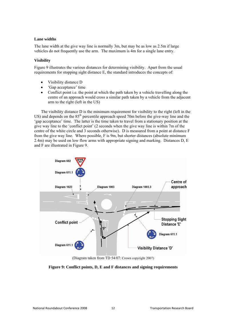
Figure 9 illustrates the various distances for determining visibility. Apart from the usual requirements for stopping sight distance E, the standard introduces the concepts of:
• Visibility distance D • ‘Gap acceptance’ time • Conflict point i.e. the point at which the path taken by a vehicle travelling along the
centre of an approach would cross a similar path taken by a vehicle from the adjacent arm to the right (left in the US)
The visibility distance D is the minimum requirement for visibility to the right (left in the
US) and depends on the 85th percentile approach speed 70m before the give-way line and the ‘gap acceptance’ time. The latter is the time taken to travel from a stationary position at the give way line to the ‘conflict point’ (2 seconds when the give way line is within 7m of the centre of the white circle and 3 seconds otherwise). D is measured from a point at distance F from the give way line. Where possible, F is 9m, but shorter distances (absolute minimum 2.4m) may be used on low flow arms with appropriate signing and marking. Distances D, E and F are illustrated in Figure 9.
(Diagram taken from TD 54/07: Crown copyright 2007)
Figure 9: Conflict points, D, E and F distances and signing requirements
National Roundabout Conference 2008 12 Transportation Research Board
Janet V Kennedy
Height of domed circle
The circle may be domed to deter light vehicles and to improve conspicuity. The maximum recommended height at its centre is 100mm for a circle of diameter 4m, with smaller diameter domed circles reduced pro rate. Domed circles should not be used if they are likely to be overrun by buses, to avoid possible discomfort to passengers.
Conspicuity
A mini-roundabout needs to be conspicuous at all times of day or night. An additional sign may need to be provided on the splitter island if kerbed. The layout and number of arms should be visible at 15m before the give way line or advance direction signs provided. A domed white circle, particularly if used in conjunction with outward sloping crossfall, can improve the conspicuity of the central island, as can a truck apron in a contrasting material.
SUMMARY
The revised geometric design standard for roundabouts, TD 16/07, is similar to the old one, but places rather greater emphasis on non-motorised users as part of a new design hierarchy. The new standard for mini-roundabouts, TD 54/07, emphasises their role as replacement junctions rather than for new-build situations, and describes details of junction design.
REFERENCES
ARCADY. Details from www.trlsoftware.co.uk Department for Transport (2006). Mini-roundabouts: good practice guidance. Design Manual for Roads and Bridges (DMRB) Volume 6, Section 2, Part 3:
TD 16/07 Geometric design of roundabout TD 78/97 Design of road markings at roundabouts TD 50/04 The geometric layout of signal controlled junctions and signalised
roundabouts Volume 6, Section 2, Part 2:
TD 54/07 Design of mini-roundabouts Volume 6, Section 3, Part 5:
TD 51/03 Segregated left turn lanes and subsidiary deflection islands at roundabouts
Volume 6, Section 3, Part 8 TA 86/03 Layout of large signal controlled junctions
Volume 5, Section 2, Part 2: HD 19/03 Safety Audit
London: The Stationery Office. www.standardsforhighways.co.uk/dmrb/index.htm Kennedy J V (2007). International comparison of roundabout design guidelines. TRL Published Project Report PPR 206. Wokingham: Transport Research Laboratory. Kennedy J V, Hall R D and Barnard S R (1998). Accidents at urban mini-roundabouts. TRL Report TRL 281. Crowthorne: Transport Research Laboratory. RODEL. Details from [email protected] Sawers C (1996). Mini-roundabouts: getting them right. http://www.mini-roundabout.com/ Sawers C (2007). Mini-roundabouts: a definitive guide. http://www.mini-roundabout.com/
National Roundabout Conference 2008 13 Transportation Research Board