the universal 3d metrology software platform for manufacturing™
TRANSCRIPT
The Universal3D Metrology
SoftwarePlatform for
Manufacturing™
Established in 1969, O'Fallon Casting is anonferrous investment casting company with
a facility located just 20 minutes west ofSt. Louis, MO, that provides rapid prototypeand production castings in a wide range of
aluminum, copper-based, and silicon carbidemetal matrix composite alloys. Since 2006,
O’Fallon Casting uses 3D scanning andPolyWorks® software to perform point-cloud-
based inspection of its patterns and cast parts.
O’Fallon Casting of St. Louis, Missouri, is a premier
nonferrous investment casting company that has built its
reputation on making high-quality, competitively priced
castings to meet demanding end-user applications.
In its 50,000 square-foot facility, the company
specializes in casting a range of aluminum,
copper-based, and silicon carbide metal
matrix composite alloys, and furnishes
castings only or castings machined to
customer specifications.
The company serves a broad range of markets including
the military missile and electronic packaging markets,
valves and pumps, medical and dental equipment,
high-speed automated precision machinery, hardware,
business machines, robotics, optical and laser equipment,
silicon wafer processing equipment, and semiconductor
manufacturing equipment.
One area of growth for the company has been in its
rapid prototyping operation. It uses expendable patterns
generated from a 3D model from a CAD file to quickly
and cost effectively produce a part and verify its design
prior to building production tooling.
CASE STUDY
2
O’Fallon CastingAdds More Speed to its Rapid Prototyping Operation with PolyWorks Software

“In recent years,
there have been
many improvements
in the quality of
pattern surface finishes,
pattern accuracy, and pattern
material alternatives, and today’s patterns are more user
friendly to the near net shapes offered by the investment
casting process,” said Ben Galmiche, O’Fallon Casting
quality engineer. Because of these improvements, rapid
prototyping of cast parts is a good value for customers
who want to reduce overall tooling costs and introduce
products into the marketplace quickly.
Quality inspection is a crucial aspect of the casting
business. Traditional inspection methods, using touch-
based methods, were not well suited to rapid prototyping.
CASE STUDY
3
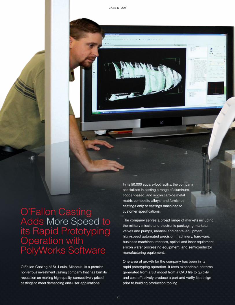
Part inspection with
Ben Galmiche (left) and
Ted Schnarre (right) from
O’Fallon Casting Inc. using
a Global CMM, a Metris
XC50 laser scanner, and
PolyWorks software.
“In the past,
we didn’t have
an effective
and efficient way
of inspecting solid
models. We had an old
cantilever-type coordinate
measuring machine and
used a touch trigger probe
to collect dimensional data.
This process was slow
and we were looking
for a new alternative.”
Ben Galmiche,
O’Fallon Casting
Quality
Engineer
CASE STUDY
4
To help enhance the turnaround time of
its rapid prototype inspection process,
O’Fallon Casting turned to 3D scanning
and point-cloud-based inspection. O’Fallon
Casting replaced the older CMM with a Global
CMM from Hexagon Metrology and equipped it with a
Metris XC50 Cross Scanner, a high-speed, multi-stripe
3D laser scanner designed for inspecting part features
that provides optimal point distribution in all directions.
This new 3D measurement system was delivered with the
PolyWorks software suite from InnovMetric Software Inc.,
the leading 3D metrology software that offers a wide
array of point cloud engineering tools for quality control
and inspection.
This investment proved to be the right
move, one that paid off quickly.
Particularly when O’Fallon
Casting received a request
in 2008 to inspect the
housing for an integrated
wing tip light of
the Boeing 787
Dreamliner.
Here’s how O’Fallon successfully integrated the
point-cloud-based analysis in all phases of its
rapid-prototyping process:
1
A pattern of the wing tip light housing was created from
the customer’s 3D CAD model of the part using stereo-
lithography (SLA) and selective laser sintering (SLS).
2
The pattern was then visually and manually inspected
to determine if it conformed to the reference CAD
model of the part and if it was properly proportioned
to account for shrinkage.
3
Once the pattern was verified and approved through the
PolyWorks inspection process, O’Fallon Casting built
a ceramic shell around the rapid prototype pattern.
4
The ceramic shell with the pattern went through a
burn out process, where the pattern was vaporized to
leave only the ceramic mold. The part was cast from
A356 aluminum artificially aged to the T6 condition.
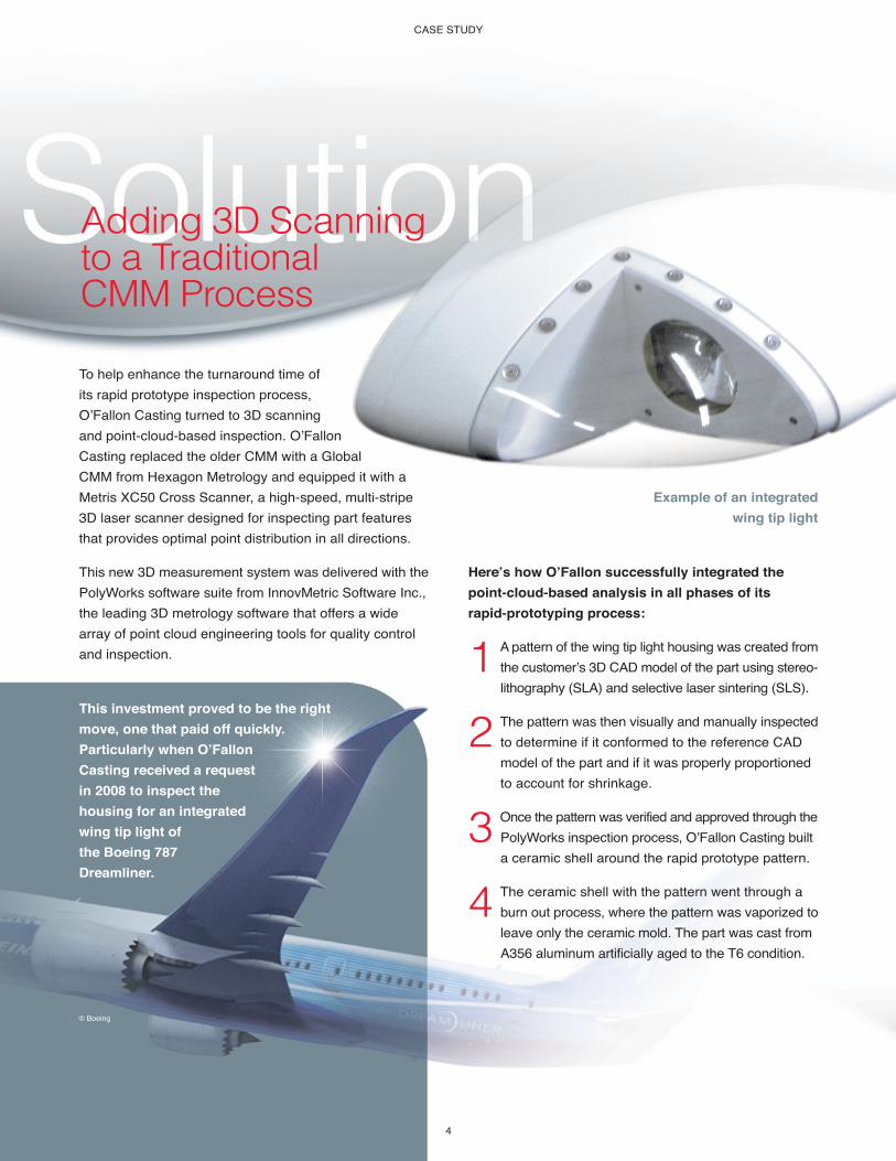
Example of an integrated
wing tip light
© Boeing
Adding 3D Scanningto a Traditional CMM Process
CASE STUDY
5
5
The part was then measured using the Global CMM and
the Metris laser scanner. The point cloud data gathered
during this routine was transferred to the PolyWorks
software electronically via the company’s internal network.
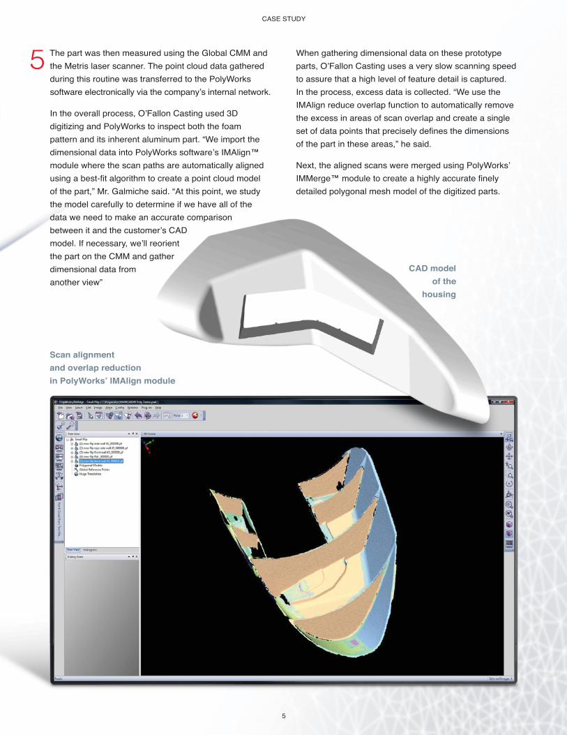
In the overall process, O’Fallon Casting used 3D
digitizing and PolyWorks to inspect both the foam
pattern and its inherent aluminum part. “We import the
dimensional data into PolyWorks software’s IMAlign™
module where the scan paths are automatically aligned
using a best-fit algorithm to create a point cloud model
of the part,” Mr. Galmiche said. “At this point, we study
the model carefully to determine if we have all of the
data we need to make an accurate comparison
between it and the customer’s CAD
model. If necessary, we’ll reorient
the part on the CMM and gather
dimensional data from
another view”
When gathering dimensional data on these prototype
parts, O’Fallon Casting uses a very slow scanning speed
to assure that a high level of feature detail is captured.
In the process, excess data is collected. “We use the
IMAlign reduce overlap function to automatically remove
the excess in areas of scan overlap and create a single
set of data points that precisely defines the dimensions
of the part in these areas,” he said.
Next, the aligned scans were merged using PolyWorks’
IMMerge™ module to create a highly accurate finely
detailed polygonal mesh model of the digitized parts.
CAD model
of the
housing
Scan alignment
and overlap reduction
in PolyWorks’ IMAlign module
CASE STUDY
6
“Using simple IMInspect tools, we can quickly see where
a part is out of tolerance relative to the customer’s
CAD model,” Mr. Galmiche said. “Because of the
flexibility of the software, we can compare the models
using different alignment methods, something that
many of our customers find very helpful.”
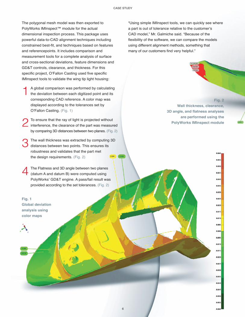
The polygonal mesh model was then exported to
PolyWorks IMInspect™ module for the actual
dimensional inspection process. This package uses
powerful data-to-CAD alignment techniques including
constrained best-fit, and techniques based on features
and referencepoints. It includes comparison and
measurement tools for a complete analysis of surface
and cross-sectional deviations, feature dimensions and
GD&T controls, clearance, and thickness. For this
specific project, O’Fallon Casting used five specific
IMInspect tools to validate the wing tip light housing:
1
A global comparison was performed by calculating
the deviation between each digitized point and its
corresponding CAD reference. A color map was
displayed according to the tolerances set by
O’Fallon Casting. (Fig. 1)
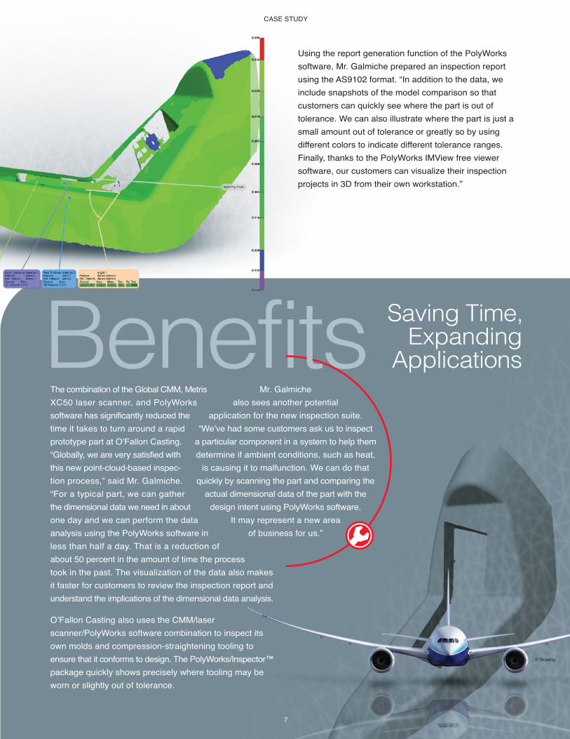
2
To ensure that the ray of light is projected without
interference, the clearance of the part was measured
by comparing 3D distances between two planes. (Fig. 2)
3
The wall thickness was extracted by computing 3D
distances between two points. This ensures its
robustness and validates that the part met
the design requirements. (Fig. 2)
4
The Flatness and 3D angle between two planes
(datum A and datum B) were computed using
PolyWorks’ GD&T engine. A pass/fail result was
provided according to the set tolerances. (Fig. 2)
Fig. 1
Global deviation
analysis using
color maps
Fig. 2
Wall thickness, clearance,
3D angle, and flatness analyses
are performed using the
PolyWorks IMInspect module
CASE STUDY
7
Using the report generation function of the PolyWorks
software, Mr. Galmiche prepared an inspection report
using the AS9102 format. “In addition to the data, we
include snapshots of the model comparison so that
customers can quickly see where the part is out of
tolerance. We can also illustrate where the part is just a
small amount out of tolerance or greatly so by using
different colors to indicate different tolerance ranges.
Finally, thanks to the PolyWorks IMView free viewer
software, our customers can visualize their inspection
projects in 3D from their own workstation.”
The combination of the Global CMM, Metris
XC50 laser scanner, and PolyWorks
software has significantly reduced the
time it takes to turn around a rapid
prototype part at O’Fallon Casting.
“Globally, we are very satisfied with
this new point-cloud-based inspec-
tion process,” said Mr. Galmiche.
“For a typical part, we can gather
the dimensional data we need in about
one day and we can perform the data
analysis using the PolyWorks software in
less than half a day. That is a reduction of
about 50 percent in the amount of time the process
took in the past. The visualization of the data also makes
it faster for customers to review the inspection report and
understand the implications of the dimensional data analysis.
O’Fallon Casting also uses the CMM/laser
scanner/PolyWorks software combination to inspect its
own molds and compression-straightening tooling to
ensure that it conforms to design. The PolyWorks/Inspector™
package quickly shows precisely where tooling may be
worn or slightly out of tolerance.
Saving Time,Expanding
ApplicationsBenefitsMr. Galmiche
also sees another potential
application for the new inspection suite.
“We’ve had some customers ask us to inspect
a particular component in a system to help them
determine if ambient conditions, such as heat,
is causing it to malfunction. We can do that
quickly by scanning the part and comparing the
actual dimensional data of the part with the
design intent using PolyWorks software.
It may represent a new area
of business for us.”
© Boeing

© 2009 InnovMetric Software Inc. All rights reserved. PolyWorks® is a registered trademark of InnovMetric Software Inc. InnovMetric, PolyWorks/Modeler, PolyWorks/Inspector, PolyWorks/Inspector Probing, IMAlign, IMMerge, IMEdit, IMCompress, IMInspect, IMSurvey, IMTexture, IMView
and “The Universal 3D Metrology Software Platform for Manufacturing” are trademarks of InnovMetric Software Inc. All other trademarks are the property of their respective owners.
HEAD OFFICEInnovMetric Software Inc.
2014, Cyrille-Duquet, Suite 310Québec QC Canada G1N 4N6
Tel. [418] 688-2061Fax [418] 688-3001
Detroit (USA, MI)Los Angeles (USA, CA)Salisbury (USA, NC)Shanghai (China)Pune (India)Lindau (Germany)
Partner office in Europe: Duwe-3d AG