the use of pyrosim for creation of the input fds geometry ... use of pyrosim for creation of the...
TRANSCRIPT
The use of PyroSim for creation of the input FDS geometry
for cinema fire simulation
LUKAS VALASEK
Slovak Academy of Sciences/Institute of Informatics
Dubravska cesta 9, 845 07 Bratislava
SLOVAK REPUBLIC
Abstract: - PyroSim is a graphical user interface developed for FDS. It is intended for efficient creation of the
input FDS representation of buildings with complex geometry. In this paper, the use of PyroSim for creating a
typical cinema with sloping floor and curved ceiling is described and simulation of a simple cinema fire
scenario is illustrated.
Key-Words: - computer simulation, cinema fire, FDS, graphical user interface, PyroSim
1 Introduction Several advanced simulation systems capable to
simulate and visualize fire in complex environments
under variable conditions, such as for instance
Fluent, SMARTFIRE, CFX, FDS, have been
developed.
Fire Dynamics Simulator (FDS) [4, 5] is a
computational fluid dynamics system developed by
NIST (National Institute of Standards and
Technology), USA. It numerically solves a form of
Navier-Stokes equations for low-speed, fire induced
flows with emphasis on transport of smoke and heat
from fire, and includes numerous physical and
chemical processes associated with fire and smoke
spread. FDS covers modelling of low-speed thermal
flows and combustion of pyrolysis products, heat
radiation and convective transfer of heat between
gases and solid surfaces, pyrolysis, flames and
smoke spread, sprinklers activation, heat and smoke
detectors, and suppression. All objects in the space
in which the fire is to be simulated must respect the
space division onto orthogonal 3D computational
meshes composed of cells. Creating the input
geometry for FDS simulations is a complicated,
labourious and time-consuming process especially
for complex models with several complicated
components. Nowadays, several advanced graphical
user interfaces (GUI) are available.
PyroSim [6] is a GUI developed by Thunderhead
Engineering Consultants, Inc., USA in order to
facilitate preparation of inputs for FDS simulations.
The main functions of PyroSim cover an interactive
creation of complex models (the use of ground
plans, creation of multiple repetitious objects,
curved walls, stairways, etc.), import of existing
input FDS files, PyroSim files and CAD files (see
also [8]). PyroSim enables importing a ground plan,
saving it as a background image and displaying it in
its 2D or 3D View modes. The background image
scale can be modified to correspond to the
computational mesh chosen for intended FDS
simulation. This feature greatly facilitates the
creation of geometry of complicated models. In the
2D View mode, there are several useful tools for
creating the basic elements and their combinations
(obstructions, holes, vents, wall holes, blocks, block
holes, rooms, particle clouds), which represent the
input FDS geometry of objects appearing in
buildings. The current PyroSim version (PyroSim
2011) includes FDS (version 5.5.3) and allows to
run FDS simulations.
In the literature, several papers related to FDS
simulations of fire in structures with a critical
concentration of people (such as a theatre,
supermarket, room, car, tunnel, car park and office)
have appeared. However, only few papers were
devoted to the use of PyroSim in such buildings
(e.g., theatre fire and compartment fire [3, 9]).
Utilizing our experience with the use of FDS for
simulation of car fire and tunnel fires [2, 10, 11], we
used FDS for several preliminary studies on cinema
fire simulation [1, 7]. In this paper, we demonstrate
creating the input FDS geometry of a chosen cinema
by PyroSim for cinema fire simulation.
The paper has the following structure. In Section
2, 3D model of a typical cinema with sloping floor
and curved ceiling is introduced. Section 3 describes
in detail creating the input FDS geometry of this
cinema using PyroSim. In Section 4, a simple
scenario of fire in the cinema is illustrated. Section 5
summarizes the main results of the paper.
Recent Advances in Systems Science and Mathematical Modelling
ISBN: 978-1-61804-141-8 304
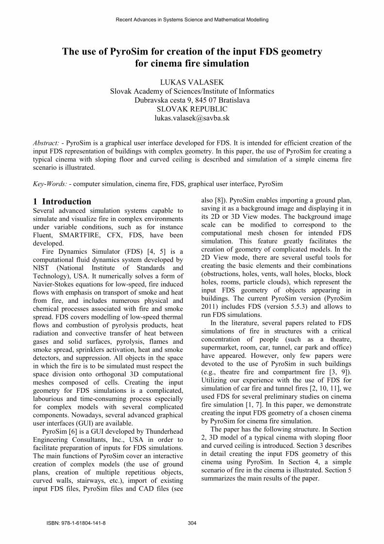
2 Cinema description In order to demonstrate the PyroSim use for FDS
cinema fire simulation, we used the Google
SketchUp to construct a 3D model of a typical
cinema which contains several complex
construction elements (see Fig. 1).
The cinema consists of the entrance hall (12,2 x
3,0 x 4,8 m and 1,6 x 12,0 x 4,8 m), projection room
Figure 1. 3D model of a cinema: cinema schemes
and cinema ground plan
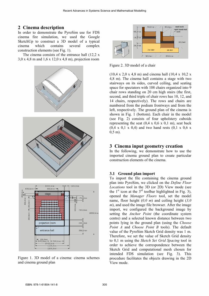
Figure 2. 3D model of a chair
(10,4 x 2,0 x 4,8 m) and cinema hall (10,4 x 10,2 x
4,8 m). The cinema hall contains a stage with two
stairways on its sides, curved ceiling, and seating
space for spectators with 108 chairs organized into 9
chair rows standing on 20 cm high stairs (the first,
second, and third triple of chair rows has 10, 12, and
14 chairs, respectively). The rows and chairs are
numbered from the podium frontways and from the
left, respectively. The ground plan of the cinema is
shown in Fig. 1 (bottom). Each chair in the model
(see Fig. 2) consists of four upholstery cuboids
representing the seat (0,4 x 0,6 x 0,1 m), seat back
(0,4 x 0,1 x 0,4) and two hand rests (0,1 x 0,6 x
0,5 m).
3 Cinema input geometry creation In the following, we demonstrate how to use the
imported cinema ground plan to create particular
construction elements of the cinema.
3.1 Ground plan import To import the file containing the cinema ground
plan into PyroSim, we clicked on the Define Floor
Locations tool in the 3D (or 2D) View mode (see
the 1st icon at the 3
rd toolbar highlighted in Fig. 3),
opened the Manager Floors tool, set the model
name, floor height (0,0 m) and ceiling height (3,0
m), and used the image file browser. After the image
import, we configured the background image by
setting the Anchor Point (the coordinate system
centre) and a selected known distance between two
points lying in the ground plan (using the Choose
Point A and Choose Point B tools). The default
value of the PyroSim Sketch Grid density was 1 m.
Therefore, we set the value of Sketch Grid density
to 0,1 m using the Sketch Set Grid Spacing tool in
order to achieve the correspondence between the
Sketch Grid and computational mesh chosen for
intended FDS simulation (see Fig. 3). This
procedure facilitates the objects drawing in the 2D
View mode.
Recent Advances in Systems Science and Mathematical Modelling
ISBN: 978-1-61804-141-8 305
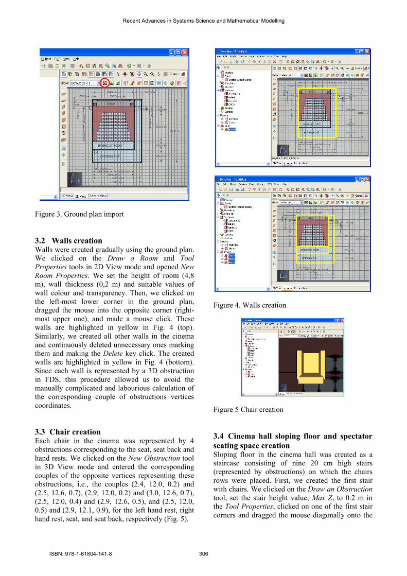
Figure 3. Ground plan import
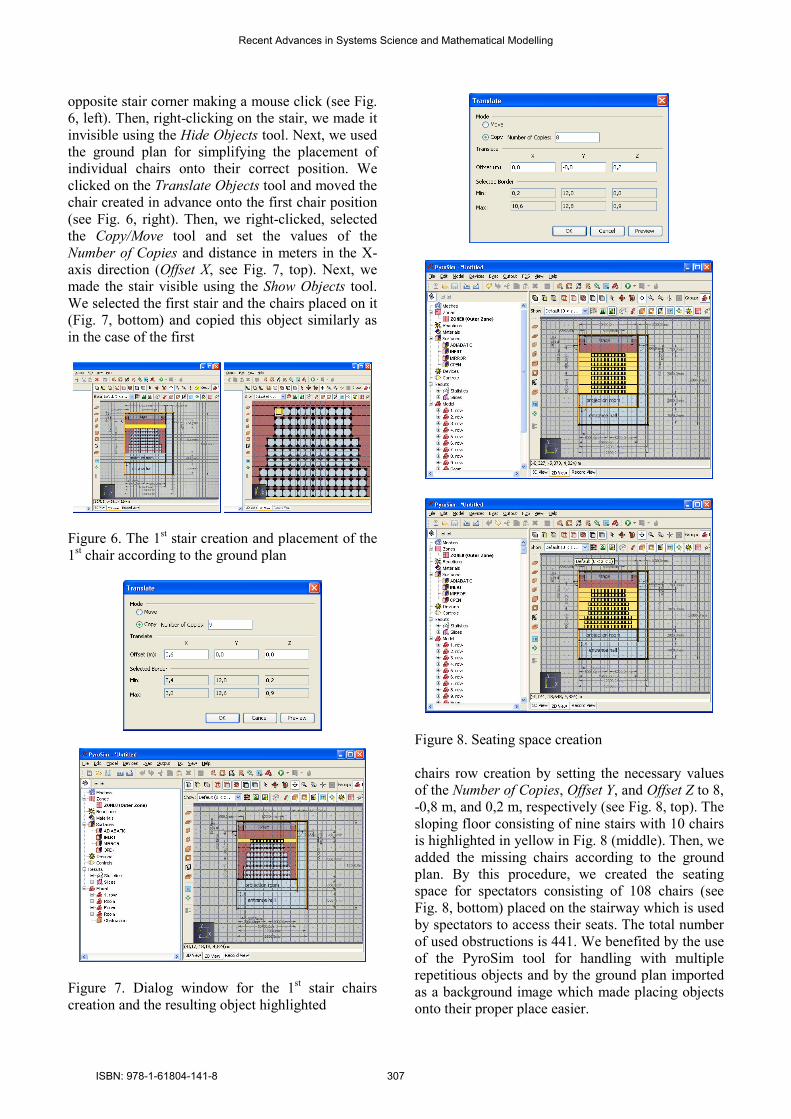
3.2 Walls creation Walls were created gradually using the ground plan.
We clicked on the Draw a Room and Tool
Properties tools in 2D View mode and opened New
Room Properties. We set the height of room (4,8
m), wall thickness (0,2 m) and suitable values of
wall colour and transparency. Then, we clicked on
the left-most lower corner in the ground plan,
dragged the mouse into the opposite corner (right-
most upper one), and made a mouse click. These
walls are highlighted in yellow in Fig. 4 (top).
Similarly, we created all other walls in the cinema
and continuously deleted unnecessary ones marking
them and making the Delete key click. The created
walls are highlighted in yellow in Fig. 4 (bottom).
Since each wall is represented by a 3D obstruction
in FDS, this procedure allowed us to avoid the
manually complicated and labourious calculation of
the corresponding couple of obstructions vertices
coordinates.
3.3 Chair creation Each chair in the cinema was represented by 4
obstructions corresponding to the seat, seat back and
hand rests. We clicked on the New Obstruction tool
in 3D View mode and entered the corresponding
couples of the opposite vertices representing these
obstructions, i.e., the couples (2.4, 12.0, 0.2) and
(2.5, 12.6, 0.7), (2.9, 12.0, 0.2) and (3.0, 12.6, 0.7),
(2.5, 12.0, 0.4) and (2.9, 12.6, 0.5), and (2.5, 12.0,
0.5) and (2.9, 12.1, 0.9), for the left hand rest, right
hand rest, seat, and seat back, respectively (Fig. 5).
Figure 4. Walls creation
Figure 5 Chair creation
3.4 Cinema hall sloping floor and spectator
seating space creation Sloping floor in the cinema hall was created as a
staircase consisting of nine 20 cm high stairs
(represented by obstructions) on which the chairs
rows were placed. First, we created the first stair
with chairs. We clicked on the Draw an Obstruction
tool, set the stair height value, Max Z, to 0.2 m in
the Tool Properties, clicked on one of the first stair
corners and dragged the mouse diagonally onto the
Recent Advances in Systems Science and Mathematical Modelling
ISBN: 978-1-61804-141-8 306
opposite stair corner making a mouse click (see Fig.
6, left). Then, right-clicking on the stair, we made it
invisible using the Hide Objects tool. Next, we used
the ground plan for simplifying the placement of
individual chairs onto their correct position. We
clicked on the Translate Objects tool and moved the
chair created in advance onto the first chair position
(see Fig. 6, right). Then, we right-clicked, selected
the Copy/Move tool and set the values of the
Number of Copies and distance in meters in the X-
axis direction (Offset X, see Fig. 7, top). Next, we
made the stair visible using the Show Objects tool.
We selected the first stair and the chairs placed on it
(Fig. 7, bottom) and copied this object similarly as
in the case of the first
Figure 6. The 1st stair creation and placement of the
1st chair according to the ground plan
Figure 7. Dialog window for the 1st stair chairs
creation and the resulting object highlighted
Figure 8. Seating space creation
chairs row creation by setting the necessary values
of the Number of Copies, Offset Y, and Offset Z to 8,
-0,8 m, and 0,2 m, respectively (see Fig. 8, top). The
sloping floor consisting of nine stairs with 10 chairs
is highlighted in yellow in Fig. 8 (middle). Then, we
added the missing chairs according to the ground
plan. By this procedure, we created the seating
space for spectators consisting of 108 chairs (see
Fig. 8, bottom) placed on the stairway which is used
by spectators to access their seats. The total number
of used obstructions is 441. We benefited by the use
of the PyroSim tool for handling with multiple
repetitious objects and by the ground plan imported
as a background image which made placing objects
onto their proper place easier.
Recent Advances in Systems Science and Mathematical Modelling
ISBN: 978-1-61804-141-8 307
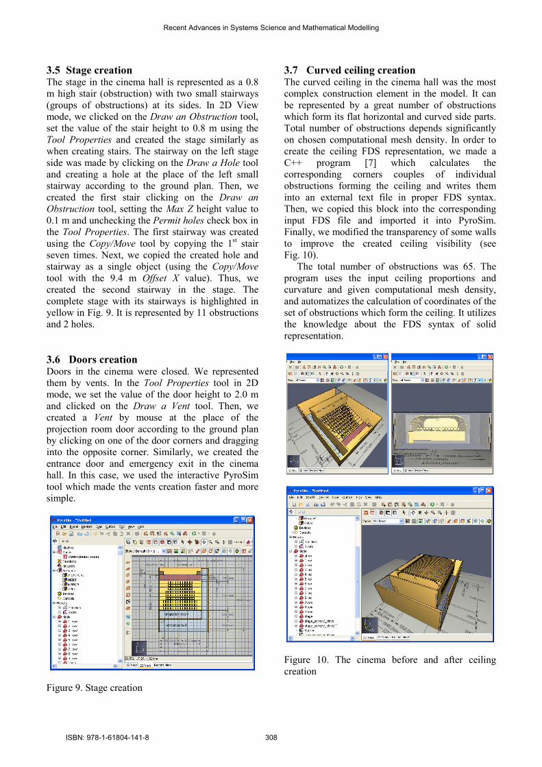
3.5 Stage creation The stage in the cinema hall is represented as a 0.8
m high stair (obstruction) with two small stairways
(groups of obstructions) at its sides. In 2D View
mode, we clicked on the Draw an Obstruction tool,
set the value of the stair height to 0.8 m using the
Tool Properties and created the stage similarly as
when creating stairs. The stairway on the left stage
side was made by clicking on the Draw a Hole tool
and creating a hole at the place of the left small
stairway according to the ground plan. Then, we
created the first stair clicking on the Draw an
Obstruction tool, setting the Max Z height value to
0.1 m and unchecking the Permit holes check box in
the Tool Properties. The first stairway was created
using the Copy/Move tool by copying the 1st stair
seven times. Next, we copied the created hole and
stairway as a single object (using the Copy/Move
tool with the 9.4 m Offset X value). Thus, we
created the second stairway in the stage. The
complete stage with its stairways is highlighted in
yellow in Fig. 9. It is represented by 11 obstructions
and 2 holes.
3.6 Doors creation Doors in the cinema were closed. We represented
them by vents. In the Tool Properties tool in 2D
mode, we set the value of the door height to 2.0 m
and clicked on the Draw a Vent tool. Then, we
created a Vent by mouse at the place of the
projection room door according to the ground plan
by clicking on one of the door corners and dragging
into the opposite corner. Similarly, we created the
entrance door and emergency exit in the cinema
hall. In this case, we used the interactive PyroSim
tool which made the vents creation faster and more
simple.
Figure 9. Stage creation
3.7 Curved ceiling creation The curved ceiling in the cinema hall was the most
complex construction element in the model. It can
be represented by a great number of obstructions
which form its flat horizontal and curved side parts.
Total number of obstructions depends significantly
on chosen computational mesh density. In order to
create the ceiling FDS representation, we made a
C++ program [7] which calculates the
corresponding corners couples of individual
obstructions forming the ceiling and writes them
into an external text file in proper FDS syntax.
Then, we copied this block into the corresponding
input FDS file and imported it into PyroSim.
Finally, we modified the transparency of some walls
to improve the created ceiling visibility (see
Fig. 10).
The total number of obstructions was 65. The
program uses the input ceiling proportions and
curvature and given computational mesh density,
and automatizes the calculation of coordinates of the
set of obstructions which form the ceiling. It utilizes
the knowledge about the FDS syntax of solid
representation.
Figure 10. The cinema before and after ceiling
creation
Recent Advances in Systems Science and Mathematical Modelling
ISBN: 978-1-61804-141-8 308
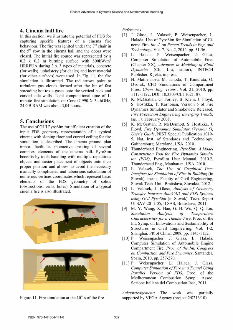
4. Cinema hall fire In this section, we illustrate the potential of FDS for
capturing specific features of a cinema fire
behaviour. The fire was ignited under the 7th chair in
the 5th row in the cinema hall and the doors were
closed. The initial fire source was represented by a
0,2 x 0,2 m burning surface with 800kW/m2
HRRPUA during 3 s. 3 types of materials, concrete
(for walls), upholstery (for chairs) and inert material
(for other surfaces) were used. In Fig. 11, the fire
simulation is illustrated. The red arrows point to
turbulent gas clouds formed after the hit of fast
spreading hot toxic gases onto the vertical back and
curved side walls. Total computational time of 1-
minute fire simulation on Core i7 990-X 3,46GHz,
24 GB RAM was about 3,04 hours.
5. Conclusions The use of GUI PyroSim for efficient creation of the
input FDS geometry representation of a typical
cinema with sloping floor and curved ceiling for fire
simulation is described. The cinema ground plan
import facilitates interactive creating of several
complex elements of the cinema hall. PyroSim
benefits by tools handling with multiple repetitious
objects and easier placement of objects onto their
proper position and allows to avoid the necessary
manually complicated and labourious calculation of
numerous vertices coordinates which represent basic
elements of the FDS geometry of solids
(obstructions, vents, holes). Simulation of a typical
cinema fire is also illustrated.
Figure 11. Fire simulation at the 10th s of the fire
References:
[1] J. Glasa, L. Valasek, P. Weisenpacher, L.
Halada, Use of PyroSim for Simulation of Ci-
nema Fire, Int. J. on Recent Trends in Eng. and
Technology, Vol. 7, No. 2, 2012, pp. 51-56.
[2] L. Halada, P. Weisenpacher, J. Glasa,
Computer Simulation of Automobile Fires
(Chapter XX), Advances in Modeling of Fluid
Dynamics (Ch. Liu, editor), INTECH
Publisher, Rijeka, in press.
[3] H. Matheislova, M. Jahoda, T. Kundrata, O.
Dvorak, CFD Simulations of Compartment
Fires, Chem. Eng. Trans., Vol. 21, 2010, pp.
1117-1122, DOI: 10.3303/CET1021187.
[4] K. McGrattan, G. Forney, B. Klein, J. Floyd,
S. Hostikka, T. Korhonen, Version 5 of Fire
Dynamics Simulator and Smokeview Released,
Fire Protection Engineering Emerging Trends,
Iss. 17, February 2008.
[5] K. McGrattan, R. McDermott, S. Hostikka, J.
Floyd, Fire Dynamics Simulator (Version 5),
User’s Guide, NIST Special Publication 1019-
5, Nat. Inst. of Standards and Technology,
Gaithersburg, Maryland, USA, 2010.
[6] Thunderhead Engineering, PyroSim: A Model
Construction Tool for Fire Dynamics Simula-
tor (FDS), PyroSim User Manual, 2010.2,
Thunderhead Eng., Manhattan, USA, 2010.
[7] L. Valasek, The Use of Graphical User
Interface for Simulation of Fire in Building (in
Slovak), thesis, Faculty of Civil Engineering,
Slovak Tech. Uni., Bratislava, Slovakia, 2012.
[8] L. Valasek, J. Glasa, Analysis of Geometry
Transfer between AutoCAD and FDS Systems
using GUI PyroSim (in Slovak), Tech. Report
UI SAV-2011-05, II SAS, Bratislava, 2011.
[9] M. Y. Wang, X. Han, G. H. Wu, Q. Q. Liu,
Simulation Analysis of Temperature
Characteristics for a Theater Fire, Proc. of the
Int. Symp. on Innovations and Sustainability of
Structures in Civil Engineering, Vol. 1-2,
Shanghai, PR of China, 2008, pp. 1145-1152.
[10] P. Weisenpacher, J. Glasa, L. Halada,
Computer Simulation of Automobile Engine
Compartment Fire, Proc. of the Int. Congress
on Combustion and Fire Dynamics, Santander,
Spain, 2010, pp. 257-270.
[11] P. Weisenpacher, L. Halada, J. Glasa,
Computer Simulation of Fire in a Tunnel Using
Parallel Version of FDS, Proc. of the
Mediterranean Combustion Symp., Assoc.
Sezione Italiana del Combustion Inst., 2011.
Acknowledgement: The work was partially
supported by VEGA Agency (project 2/0216/10).
Recent Advances in Systems Science and Mathematical Modelling
ISBN: 978-1-61804-141-8 309