the visionary eye · konica minolta range7 will change the process of manufacturing. problems can...
TRANSCRIPT
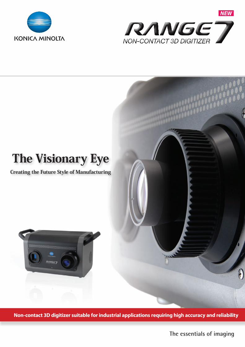
Non-contact 3D digitizer suitable for industrial applications requiring high accuracy and reliability
The Visionary EyeCreating the Future Style of Manufacturing
NEW
Osaka, Japan EMail : [email protected] Web : http://konicaminolta.com/instruments
Konica Minolta Sensing Americas, Inc. New Jersey , U.S.A. Phone: 888-473-2656 (in USA), 201-236-4300 (outside USA) Fax: 201-785-2482 EMail : [email protected] Web : http://se.konicaminolta.us/3d
Konica Minolta Sensing Europe B.V. German Office München, Germany Phone: +49 (0) 89 630267-9700 Fax: +49 (0) 89 630267-9799 EMail : [email protected] Web : http://www.konicaminolta.eu French Office Roissy CDG, France Phone : +33(0)1 493-82519 Fax: +33(0)1 493-84771 EMail : [email protected] Web : http://www.konicaminolta.eu UK Office Milton Keynes, United Kingdom Phone : +44(0)1908 540-622 Fax: +44(0)1908 540-629 EMail : [email protected] Web : http://www.konicaminolta.eu Italian Office Milan, Italy Phone : +39 02 390111 Fax: +39 02 39011.223 EMail : [email protected] Web : http://www.konicaminolta.eu Polish Office Wroclaw, Poland Phone : +48 71 734 52 11 Fax: +48 71 734 52 10 EMail : [email protected] Web : http://www.konicaminolta.eu
Konica Minolta (CHINA) Investment Ltd. SE Sales Division Shanghai, China Phone: +86-021-5489 0202 Fax: +86-021-5489 0005Konica Minolta Sensing Singapore Pte Ltd. Singapore Phone: +65 6563-5533 Fax: +65 6560-9721

KONICA MINOLTA
Do you make 2D drawings simply to
check your 3D model?
How reliable is your surface profile
eva lua tion, suc h as c hec king of
distortion in a free-form surface?
Is the evaluation of wall thickness or
machining stock inspection for cast
parts sufficient?
D o y o u s p e n d t o o m u c h t i m e
correcting the dies for press parts?
Are the bosses, ribs and holes of
plastic parts formed in accordance
with the original design?
Is inspection totally dependent on
skilled workers?
Q
■ Principal applications and measurement targetsQuality inspection (confirmation and verification of whether parts are manufactured to specifications) and reverse engineering (quantification of quality and capability of parts, etc.) from development to prototyping phases
• Cast and other formed materials • Pressed parts • Injection molded parts • Various machined parts
• Reverse engineering • Rapid prototyping • Creation of machining data • Digital mockup
Non-contact 3D digitizer KONICA MINOLTA RANGE7 can instantaneously digitize the external profiles of various industrial parts, including press parts, machined parts, dies, prototypes, cast parts and injection molded parts, into 3D data. The digitized profile data can then be accurately reproduced on a computer screen. By comparing this data against 3D CAD data with optional application software, you can quickly output measurement reports on overall deviation, cross-sectional deviation, wall thickness distribution and GD&T (Geometric Dimensioning and Tolerance). This allows increased speed and improved quality in the manufacturing process.In addition to measurement for inspection and quality control, KONICA MINOLTA RANGE7 offers various applications including:
KONICA MINOLTA RANGE7 opens up the future possibilities of non-contact 3D measurement by adding the elements of increased reliability, improved operability and easier transportability to Konica Minolta's accumulated optical technologies and auto-focus function.
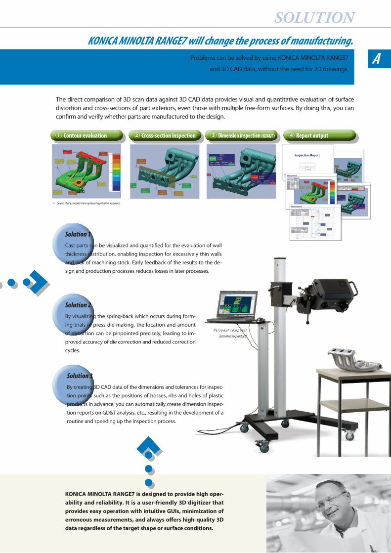
① Contour evaluation ② Cross-section inspection ③ Dimension inspection (GD&T) ④ Report output
Measurement
TotalNumberAverageUpper limitLower limitDifferenceStandardAverage
Name Type Measured value (mm)
DistanceDistanceDistanceDistanceDistanceDistance
GD&T
Name Standard Difference Upper limit Lower limit Date/timeDistanceDistance
Inspection Report
Measurement
Name TypeMeasuredvalue
DistanceDistanceDistanceDistanceDistanceDistanceDistance
Measurement
Name Type Measured value
Name Type Measured value
DistanceDistanceDistance
radiusradius
* Screen shot examples from optional application software.
A
SOLUTIONKONICA MINOLTA RANGE7 will change the process of manufacturing.
Problems can be solved by using KONICA MINOLTA RANGE7
and 3D CAD data, without the need for 2D drawings.
Solution 1Cast parts can be visualized and quantified for the evaluation of wall
thickness distribution, enabling inspection for excessively thin walls
and lack of machining stock. Early feedback of the results to the de-
sign and production processes reduces losses in later processes.
Solution 2By visualizing the spring-back which occurs during form-
ing trials in press die making, the location and amount
of distortion can be pinpointed precisely, leading to im-
proved accuracy of die correction and reduced correction
cycles.
Solution 3By creating 3D CAD data of the dimensions and tolerances for inspec-
tion points such as the positions of bosses, ribs and holes of plastic
products in advance, you can automatically create dimension inspec-
tion reports on GD&T analysis, etc., resulting in the development of a
routine and speeding up the inspection process.
The direct comparison of 3D scan data against 3D CAD data provides visual and quantitative evaluation of surface distortion and cross-sections of part exteriors, even those with multiple free-form surfaces. By doing this, you can confirm and verify whether parts are manufactured to the design.
KONICA MINOLTA RANGE7 is designed to provide high oper-ability and reliability. It is a user-friendly 3D digitizer that provides easy operation with intuitive GUIs, minimization of erroneous measurements, and always offers high-quality 3D data regardless of the target shape or surface conditions.
P e r s o n a l c o m p u t e r (commercial product)
A
01 Easy-to-carry digitizer with integrated camera and controller
The KONICA MINOLTA RANGE7 is a new 3D digitizer series full
of 3D digitizing know-how accumulated from Konica Minolta's
over 10 years of experience. The compact and lightweight
design integrates the camera and controller in a single body
weighing only approximately 6.7 kg, providing high mobility
on measurement sites. The two interchangeable lenses allow
one digitizer to handle a broad measurement range.
02 Various focusing functions for quick capturing of clear 3D data
The auto-focus (AF) function implements further advances that
only Konica Minolta could provide, to offer a multi-focus mode
which automatically shifts the focus position in two steps to
obtain more accurate and sharper 3D measurement data. This
is especially effective for measurement of deep objects. The ad-
justment of distance and angle of view is also easy by using the
point AF function which adjusts the focus to the point specified
by the user and the Field of View (FOV) indicator which shows
the current measurement area.
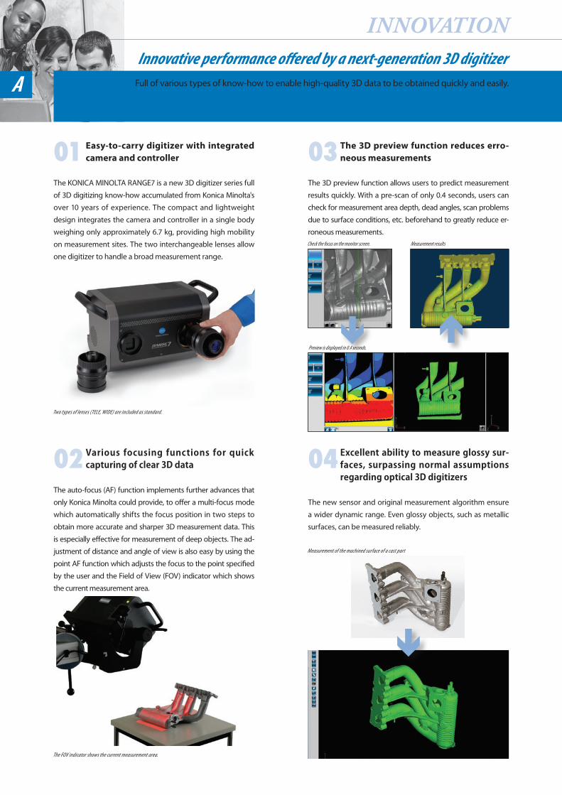
03 The 3D preview function reduces erro-neous measurements
The 3D preview function allows users to predict measurement
results quickly. With a pre-scan of only 0.4 seconds, users can
check for measurement area depth, dead angles, scan problems
due to surface conditions, etc. beforehand to greatly reduce er-
roneous measurements.
04 Excellent ability to measure glossy sur-faces, surpassing normal assumptions regarding optical 3D digitizers
The new sensor and original measurement algorithm ensure
a wider dynamic range. Even glossy objects, such as metallic
surfaces, can be measured reliably.
INNOVATIONInnovative performance of ered by a next-generation 3D digitizer
Full of various types of know-how to enable high-quality 3D data to be obtained quickly and easily.
Two types of lenses (TELE, WIDE) are included as standard.
The FOV indicator shows the current measurement area.
Check the focus on the monitor screen. Measurement results
Preview is displayed in 0.4 seconds.
Measurement of the machined surface of a cast part
USABILITYThe newly developed software RANGE VIEWER allows comfortable scanning operations.
The software, designed specifically for KONICA MINOLTA RANGE7, makes the process
from scanning to data integration quick and easy.
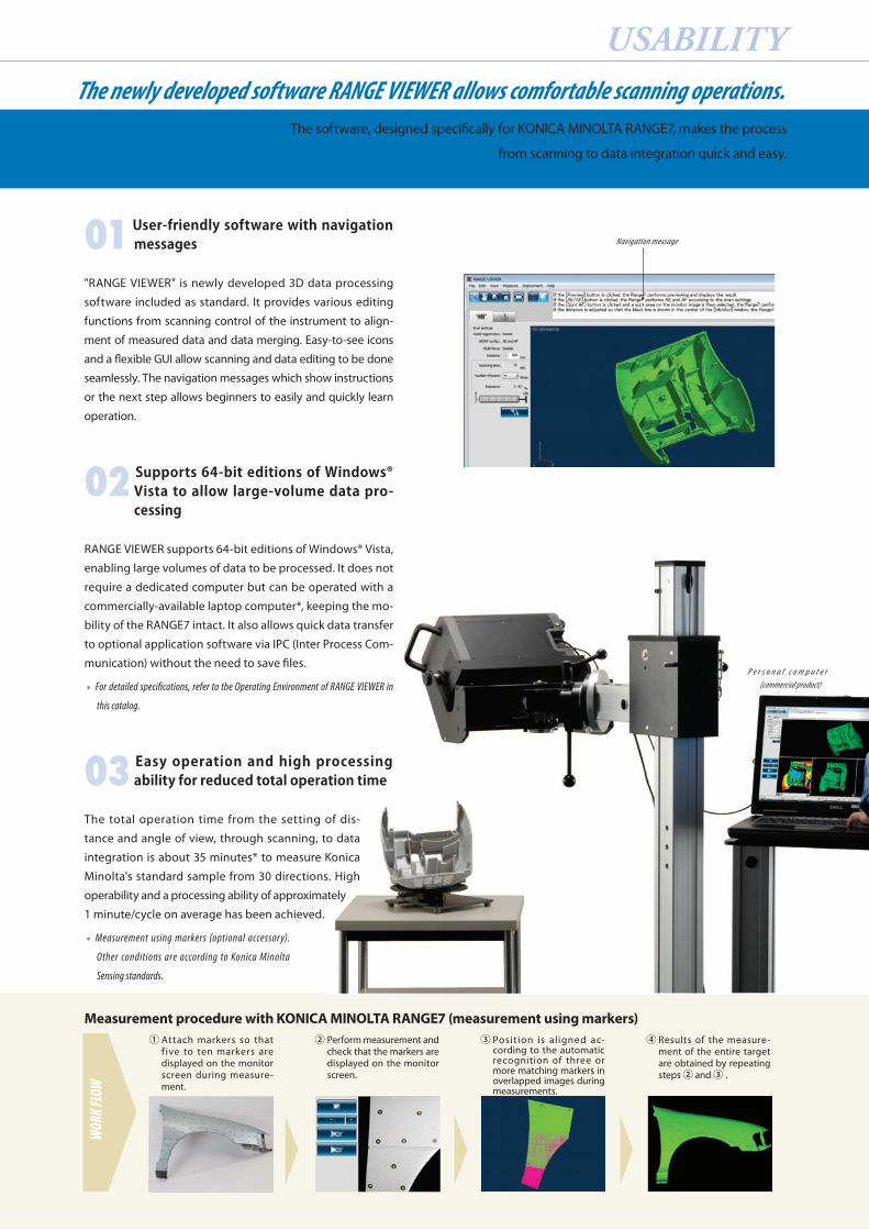
01 User-friendly software with navigation messages
"RANGE VIEWER" is newly developed 3D data processing
software included as standard. It provides various editing
functions from scanning control of the instrument to align-
ment of measured data and data merging. Easy-to-see icons
and a flexible GUI allow scanning and data editing to be done
seamlessly. The navigation messages which show instructions
or the next step allows beginners to easily and quickly learn
operation.
02 Supports 64-bit editions of Windows® Vista to allow large-volume data pro-cessing
RANGE VIEWER supports 64-bit editions of Windows® Vista,
enabling large volumes of data to be processed. It does not
require a dedicated computer but can be operated with a
commercially-available laptop computer*, keeping the mo-
bility of the RANGE7 intact. It also allows quick data transfer
to optional application software via IPC (Inter Process Com-
munication) without the need to save files.
* For detailed specifications, refer to the Operating Environment of RANGE VIEWER in
this catalog.
03 Easy operation and high processing ability for reduced total operation time
The total operation time from the setting of dis-
tance and angle of view, through scanning, to data
integration is about 35 minutes* to measure Konica
Minolta's standard sample from 30 directions. High
operability and a processing ability of approximately
1 minute/cycle on average has been achieved.
* Measurement using markers (optional accessory).
Other conditions are according to Konica Minolta
Sensing standards.
① Attach markers so that f ive to ten markers are displayed on the monitor screen during measure-ment.
② Perform measurement and check that the markers are displayed on the monitor screen.
③ Position is aligned ac-cording to the automatic recognition of three or more matching markers in overlapped images during measurements.
④ Results of the measure-ment of the entire target are obtained by repeating steps ② and ③ .
Measurement procedure with KONICA MINOLTA RANGE7 (measurement using markers)
WORK
FLOW
Navigation message
P e r s o n a l c o m p u t e r (commercial product)
E F
79
8
101
2
3
5
64
D
H
AB
G
C
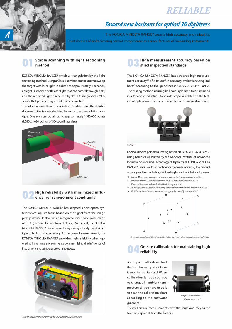
01 Stable scanning with light sectioning method
KONICA MINOLTA RANGE7 employs triangulation by the light
sectioning method, using a Class-2 semiconductor laser to sweep
the target with laser light. In as little as approximately 2 seconds,
a target is scanned with laser light that has passed through a slit,
and the reflected light is received by the 1.31-megapixel CMOS
sensor that provides high-resolution information.
The information is then converted into 3D data using the data for
distance to the target calculated based on the triangulation prin-
ciple. One scan can obtain up to approximately 1,310,000 points
(1,280 x 1,024 points) of 3D coordinate data.
02 High reliability with minimized influ-ence from environment conditions
The KONICA MINOLTA RANGE7 has adopted a new optical sys-
tem which adjusts focus based on the signal from the image
pickup device. It also has an integrated inner base-plate made
of CFRP (carbon fiber reinforced plastic). As a result, the KONICA
MINOLTA RANGE7 has achieved a lightweight body, great rigid-
ity and high driving accuracy. At the time of measurement, the
KONICA MINOLTA RANGE7 provides high reliability when op-
erating in various environments by minimizing the influence of
instrument tilt, temperature changes, etc.
03 High measurement accuracy based on strict inspection standards
The KONICA MINOLTA RANGE7 has achieved high measure-
ment accuracy*1 of ±40 μm*2 in accuracy evaluation using ball
bars*3 according to the guidelines in "VDI/VDE 2634*4 Part 2".
The testing method utilizing ball bars is planned to be included
in a Japanese Industrial Standards proposal related to the test-
ing of optical non-contact coordinate measuring instruments.
Konica Minolta performs testing based on "VDI/VDE 2634 Part 2"
using ball bars calibrated by the National Institute of Advanced
Industrial Science and Technology of Japan for all KONICA MINOLTA
RANGE7 units. We build confidence by clearly indicating the product
accuracy and by conducting strict testing for each unit before shipment.*1 Accuracy: Measuring instrument accuracy expressed as error limits under the defi ned conditions.*2 Measured with the TELE lens at a distance of 450 mm and ambient temperature of 20±1°C.
Other conditions are according to Konica Minolta Sensing standards.*3 Ball bar: Equipment for evaluation of accuracy, consisting of a bar that has balls attached at both ends.*4 VDI/VDE 2634: Optical measurement system testing guidelines issued by Germany in 2002.
Measurement of a ball bar at 10 positions inside a defined space as pre-shipment inspection (conceptual image)
04 On-site calibration for maintaining high reliability
A compact calibration chart
that can be set up on a table
is supplied as standard. When
calibration is required due
to changes in ambient tem-
perature, all you have to do is
to scan the calibration chart
according to the software
guidance.
This will ensure measurements with the same accuracy as the
time of shipment from the factory.
RELIABLEToward new horizons for optical 3D digitizersThe KONICA MINOLTA RANGE7 boasts high accuracy and reliability.
Points Konica Minolta Sensing cannot compromise as a manufacturer of measuring instruments.A
Compact calibration chart (standard accessory)
Ball bars
CMOS sensor
CFRP box structure offering great rigidity and temperature characteristics
M e a s u r e m e n t target
Laser light
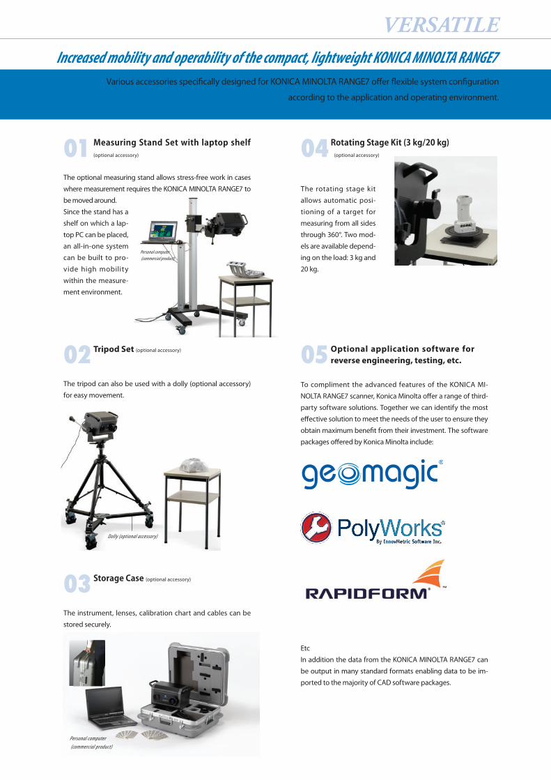
01 Measuring Stand Set with laptop shelf (optional accessory)
The optional measuring stand allows stress-free work in cases
where measurement requires the KONICA MINOLTA RANGE7 to
be moved around.
Since the stand has a
shelf on which a lap-
top PC can be placed,
an all-in-one system
can be built to pro-
vide high mobility
within the measure-
ment environment.
02 Tripod Set (optional accessory)
The tripod can also be used with a dolly (optional accessory)
for easy movement.
03 Storage Case (optional accessory)
The instrument, lenses, calibration chart and cables can be
stored securely.
04 Rotating Stage Kit (3 kg/20 kg) (optional accessory)
The rotating stage kit
allows automatic posi-
tioning of a target for
measuring from all sides
through 360°. Two mod-
els are available depend-
ing on the load: 3 kg and
20 kg.
05 Optional application software for reverse engineering, testing, etc.
To compliment the advanced features of the KONICA MI-
NOLTA RANGE7 scanner, Konica Minolta offer a range of third-
party software solutions. Together we can identify the most
effective solution to meet the needs of the user to ensure they
obtain maximum benefit from their investment. The software
packages offered by Konica Minolta include:
Etc
In addition the data from the KONICA MINOLTA RANGE7 can
be output in many standard formats enabling data to be im-
ported to the majority of CAD software packages.
VERSATILEIncreased mobility and operability of the compact, lightweight KONICA MINOLTA RANGE7
Various accessories specifically designed for KONICA MINOLTA RANGE7 offer flexible system configuration
according to the application and operating environment.
Personal computer (commercial product)
Dolly (optional accessory)
Personal computer (commercial product)
©2008 KONICA MINOLTA SENSING,INC. 9242-4892-50 AIEAPK 1
Specifications and appearance shown herein subject to change without notice.• Company names and product names used herein are trademarks or registered trademarks of their respective com-• panies.Screens shown are for illustration purpose only.•
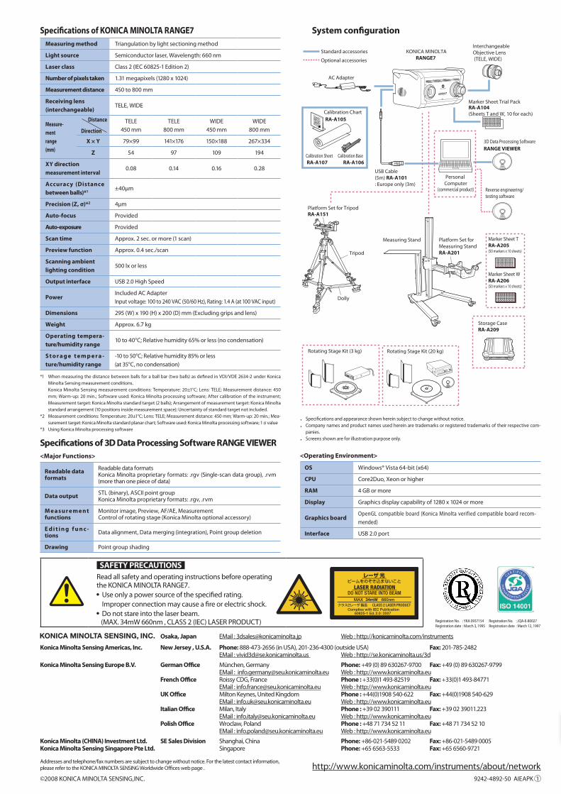
Specifications of KONICA MINOLTA RANGE7Measuring method Triangulation by light sectioning method
Light source Semiconductor laser, Wavelength: 660 nm
Laser class Class 2 (IEC 60825-1 Edition 2)
Number of pixels taken 1.31 megapixels (1280 x 1024)
Measurement distance 450 to 800 mm
Receiving lens (interchangeable)
TELE, WIDE
Measure-mentrange(mm)
TELE450 mm
TELE800 mm
WIDE450 mm
WIDE800 mm
X × Y 79×99 141×176 150×188 267×334
Z 54 97 109 194
XY direction measurement interval
0.08 0.14 0.16 0.28
Accuracy (Distance between balls)*1 ±40μm
Precision (Z, σ)*2 4μm
Auto-focus Provided
Auto-exposure Provided
Scan time Approx. 2 sec. or more (1 scan)
Preview function Approx. 0.4 sec./scan
Scanning ambient lighting condition
500 lx or less
Output interface USB 2.0 High Speed
PowerIncluded AC AdapterInput voltage: 100 to 240 VAC (50/60 Hz), Rating: 1.4 A (at 100 VAC input)
Dimensions 295 (W) x 190 (H) x 200 (D) mm (Excluding grips and lens)
Weight Approx. 6.7 kg
Operating tempera-ture/humidity range
10 to 40°C; Relative humidity 65% or less (no condensation)
S t o r a g e t e m p e r a -ture/humidity range
-10 to 50°C; Relative humidity 85% or less (at 35°C, no condensation)
*1 When measuring the distance between balls for a ball bar (two balls) as defined in VDI/VDE 2634-2 under Konica Minolta Sensing measurement conditions.
Konica Minolta Sensing measurement conditions: Temperature: 20±1°C; Lens: TELE; Measurement distance: 450 mm; Warm-up: 20 min.; Software used: Konica Minolta processing software; After calibration of the instrument; Measurement target: Konica Minolta standard target (2 balls); Arrangement of measurement target: Konica Minolta standard arrangement (10 positions inside measurement space); Uncertainty of standard target not included.
*2 Measurement conditions: Temperature: 20±1°C; Lens: TELE; Measurement distance: 450 mm; Warm-up: 20 min.; Mea-surement target: Konica Minolta standard planar chart; Software used: Konica Minolta processing software; 1 σ value
*3 Using Konica Minolta processing software
Specifications of 3D Data Processing Software RANGE VIEWER <Major Functions>
Readable data formats
Readable data formatsKonica Minolta proprietary formats: .rgv (Single-scan data group), .rvm (more than one piece of data)
Data output STL (binary), ASCII point groupKonica Minolta proprietary formats: .rgv, .rvm
M e a sur e m e nt functions
Monitor image, Preview, AF/AE, MeasurementControl of rotating stage (Konica Minolta optional accessory)
E d i t i n g f u n c -tions Data alignment, Data merging (integration), Point group deletion
Drawing Point group shading
System configurationInterchangeable Objective Lens (TELE, WIDE)
KONICA MINOLTARANGE7
AC Adapter
USB Cable(5m) RA-A101: Europe only (3m)
Marker Sheet Trial Pack
(Sheets T and W, 10 for each)
RANGE VIEWER
Personal Computer
(commercial product)
Standard accessories
Optional accessories
3D Data Processing Software
Rotating Stage Kit (3 kg) Rotating Stage Kit (20 kg)
Platform Set for TripodRA-A151
Measuring Stand Platform Set forMeasuring StandRA-A201
Marker Sheet TRA-A205(50 markers x 10 sheets)
Marker Sheet WRA-A206(50 markers x 10 sheets)
Storage CaseRA-A209
Reverse engineering/testing software
Calibration Sheet
Calibration ChartRA-A105
RA-A107Calibration Base
RA-A106
RA-A104
Dolly
Tripod
<Operating Environment>
OS Windows® Vista 64-bit (x64)
CPU Core2Duo, Xeon or higher
RAM 4 GB or more
Display Graphics display capability of 1280 x 1024 or more
Graphics boardOpenGL compatible board (Konica Minolta verified compatible board recom-mended)
Interface USB 2.0 port
Distance
Direction
SAFETY PRECAUTIONS Read all safety and operating instructions before operating the KONICA MINOLTA RANGE7. Use only a power source of the specified rating.
Improper connection may cause a fire or electric shock. Do not stare into the laser beam.
(MAX. 34mW 660nm , CLASS 2 (IEC) LASER PRODUCT)
34mW
http://www.konicaminolta.com/instruments/about/networkAddresses and telephone/fax numbers are subject to change without notice. For the latest contact information, please refer to the KONICA MINOLTA SENSING Worldwide Offices web page .
Registration No. : YKA 0937154Registration date : March 3, 1995
Registration No. : JQA-E-80027Registration date : March 12, 1997
Osaka, Japan EMail : [email protected] Web : http://konicaminolta.com/instruments
Konica Minolta Sensing Americas, Inc. New Jersey , U.S.A. Phone: 888-473-2656 (in USA), 201-236-4300 (outside USA) Fax: 201-785-2482 EMail : [email protected] Web : http://se.konicaminolta.us/3d
Konica Minolta Sensing Europe B.V. German Office München, Germany Phone: +49 (0) 89 630267-9700 Fax: +49 (0) 89 630267-9799 EMail : [email protected] Web : http://www.konicaminolta.eu French Office Roissy CDG, France Phone : +33(0)1 493-82519 Fax: +33(0)1 493-84771 EMail : [email protected] Web : http://www.konicaminolta.eu UK Office Milton Keynes, United Kingdom Phone : +44(0)1908 540-622 Fax: +44(0)1908 540-629 EMail : [email protected] Web : http://www.konicaminolta.eu Italian Office Milan, Italy Phone : +39 02 390111 Fax: +39 02 39011.223 EMail : [email protected] Web : http://www.konicaminolta.eu Polish Office Wroclaw, Poland Phone : +48 71 734 52 11 Fax: +48 71 734 52 10 EMail : [email protected] Web : http://www.konicaminolta.eu
Konica Minolta (CHINA) Investment Ltd. SE Sales Division Shanghai, China Phone: +86-021-5489 0202 Fax: +86-021-5489 0005Konica Minolta Sensing Singapore Pte Ltd. Singapore Phone: +65 6563-5533 Fax: +65 6560-9721
Industry’s top level
Eliminates measurement errors caused by uneven spray layer thickness!
Eliminates need for preparation and disposal of sprayed objects!
Reduces environmental loads by eliminating spray and cleaning fluids!
Able to scan in a normal working environment (office environment*3)!
Eliminates the need for a darkroom (supplemental equipment)!
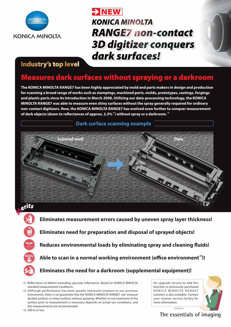
Dark surface scanning example
*1. Reflectance at 660nm excluding specular reflectance. Based on KONICA MINOLTA standard measurement conditions.
*2. Although performance has been greatly improved compare to our previous instruments, there is no guarantee that the KONICA MINOLTA RANGE7 can measure all dark surfaces or shiny surfaces without spraying. Whether or not treatment of the surface prior to measurement is necessary depends on actual use conditions, and test measurements are recommended.
*3. 500 lx or less
An upgrade service to add this function to previously purchased K O N I C A M I N O LTA R A N G E 7 scanners is also available. Contact your nearest service facility for more information.
Measures dark surfaces without spraying or a darkroomThe KONICA MINOLTA RANGE7 has been highly appreciated by mold and parts makers in design and production for scanning a broad range of works such as stampings, machined parts, molds, prototypes, castings, forgings and plastic parts since its introduction in March 2008. Utilizing our data-processing technology, the KONICA MINOLTA RANGE7 was able to measure even shiny surfaces without the spray generally required for ordinary non-contact digitizers. Now, the KONICA MINOLTA RANGE7 has evolved even further to conquer measurement of dark objects (down to reflectances of approx. 2.5%*1) without spray or a darkroom.*2
NEW
Scanned work Data
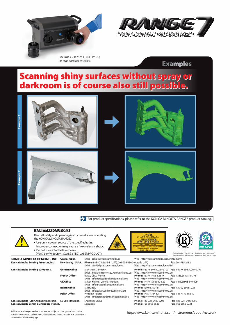
ExamplesIncludes 2 lenses (TELE, WIDE) as standard accessories.
Exam
ple
1Ex
ampl
e 2
For product specifications, please refer to the KONICA MINOLTA RANGE7 product catalog.
Scanning shiny surfaces without spray or darkroom is of course also still possible.Scanning shiny surfaces without spray or darkroom is of course also still possible.
SAFETY PRECAUTIONS Read all safety and operating instructions before operating the KONICA MINOLTA RANGE7. Use only a power source of the specified rating.
Improper connection may cause a fire or electric shock. Do not stare into the laser beam.
(MAX. 34mW 660nm , CLASS 2 (IEC) LASER PRODUCT)
34mW
http://www.konicaminolta.com/instruments/about/networkAddresses and telephone/fax numbers are subject to change without notice. For the latest contact information, please refer to the KONICA MINOLTA SENSING Worldwide Offices web page .
Registration No. : YKA 0937154Registration date : March 3, 1995
Registration No. : JQA-E-80027Registration date : March 12, 1997
Osaka, Japan EMail : [email protected] Web : http://konicaminolta.com/instrumentsKonica Minolta Sensing Americas, Inc. New Jersey , U.S.A. Phone: 888-473-2656 (in USA), 201-236-4300 (outside USA) Fax: 201-785-2482 EMail : [email protected] Web : http://se.konicaminolta.us/3d
Konica Minolta Sensing Europe B.V. German Office München, Germany Phone: +49 (0) 89 630267-9700 Fax: +49 (0) 89 630267-9799 EMail : [email protected] Web : http://www.konicaminolta.eu French Office Roissy CDG, France Phone : +33(0)1 493-82519 Fax: +33(0)1 493-84771 EMail : [email protected] Web : http://www.konicaminolta.eu UK Office Milton Keynes, United Kingdom Phone : +44(0)1908 540-622 Fax: +44(0)1908 540-629 EMail : [email protected] Web : http://www.konicaminolta.eu Italian Office Milan, Italy Phone : +39 02 390111 Fax: +39 02 39011.223 EMail : [email protected] Web : http://www.konicaminolta.eu Polish Office Wroclaw, Poland Phone : +48 71 734 52 11 Fax: +48 71 734 52 10 EMail : [email protected] Web : http://www.konicaminolta.eu
Konica Minolta (CHINA) Investment Ltd. SE Sales Division Shanghai, China Phone: +86-021-5489 0202 Fax: +86-021-5489 0005Konica Minolta Sensing Singapore Pte Ltd. Singapore Phone: +65 6563-5533 Fax: +65 6560-9721